CN102800985A - Array metamaterial antenna - Google Patents
Array metamaterial antennaDownload PDFInfo
- Publication number
- CN102800985A CN102800985ACN2011101810002ACN201110181000ACN102800985ACN 102800985 ACN102800985 ACN 102800985ACN 2011101810002 ACN2011101810002 ACN 2011101810002ACN 201110181000 ACN201110181000 ACN 201110181000ACN 102800985 ACN102800985 ACN 102800985A
- Authority
- CN
- China
- Prior art keywords
- metamaterial
- sheet
- same
- artificial
- radius
- Prior art date
- Legal status (The legal status is an assumption and is not a legal conclusion. Google has not performed a legal analysis and makes no representation as to the accuracy of the status listed.)
- Pending
Links
Images


Landscapes
- Prostheses (AREA)
Abstract
Description
Translated fromChinese技术领域technical field
本发明涉及通信领域,更具体地说,涉及一种阵列式超材料天线。The present invention relates to the communication field, and more specifically relates to an array type metamaterial antenna.
背景技术Background technique
阵列天线是一类由两个或两个以上天线单元规则或随机排列并通过适当激励获得预定辐射特性的特殊天线。就发射天线来说,简单的辐射源比如点源,对称振子源是常见的构成阵列天线的辐射源。它们按照直线或者更复杂的形式,根据天线馈电电流,间距,电长度等不同参数来构成阵列,以获取最好的辐射方向性。An array antenna is a special antenna that is arranged regularly or randomly by two or more antenna elements and obtains predetermined radiation characteristics through proper excitation. As far as the transmitting antenna is concerned, simple radiation sources such as point sources and symmetrical oscillator sources are common radiation sources that constitute array antennas. They form an array in a straight line or in a more complex form according to different parameters such as antenna feed current, spacing, and electrical length, in order to obtain the best radiation directivity.
现有技术是通过把各个实际的天线单元一个个加工出来,并排列起来以实现平面阵列,比如说平面缝隙天线阵列,就是在导体上割出一个个特定尺寸,相距特定间距的缝隙。The existing technology is to process each actual antenna unit one by one and arrange them to realize a planar array. For example, a planar slot antenna array is to cut out slots of a specific size and a specific distance apart on the conductor.
现有技术形成阵列天线的方法很机械,就是重复一个个天线单元的加工,加工工艺复杂,制造成本高。The prior art method for forming an array antenna is very mechanical, that is, repeating the processing of each antenna unit, the processing technology is complicated, and the manufacturing cost is high.
发明内容Contents of the invention
本发明所要解决的技术问题是,针对现有技术阵列式天线加工工艺复杂,制造成本高的缺陷,提供一种加工简单、制造成本低的阵列式超材料天线。The technical problem to be solved by the present invention is to provide an array metamaterial antenna with simple processing and low manufacturing cost for the defects of complex processing technology and high manufacturing cost of the prior art array antenna.
本发明解决其技术问题所采用的技术方案是:一种阵列式超材料天线,所述天线由多个超材料组成,每一超材料均由至少一个片层组成,每一片层包括片状的基材以及设置在基材上的多个人造孔结构。The technical solution adopted by the present invention to solve the technical problem is: an arrayed metamaterial antenna, the antenna is composed of a plurality of metamaterials, each metamaterial is composed of at least one sheet, and each sheet includes a sheet-shaped A base material and a plurality of artificial hole structures arranged on the base material.
进一步地,所述多个超材料为汇聚超材料、发散超材料及偏折超材料中的一种或其组合。Further, the plurality of metamaterials is one or a combination of convergent metamaterials, divergent metamaterials and deflection metamaterials.
进一步地,每一超材料均由多个相互平行的片层堆叠形成。Further, each metamaterial is formed by stacking a plurality of parallel sheets.
进一步地,所述基材分成多个相同的基材单元,每一基材单元与其上的人造孔结构构成一个超材料单元,每一基材单元的长、宽及高的尺寸均不大于入射电磁波波长的五分之一。Further, the base material is divided into a plurality of identical base material units, and each base material unit and the artificial hole structure on it form a metamaterial unit, and the length, width and height of each base material unit are not larger than the incident One-fifth of the wavelength of electromagnetic waves.
进一步地,所述每一基材单元为一立方体,所述每一基材单元的边长为入射电磁波波长的十分之一。Further, each of the substrate units is a cube, and the side length of each of the substrate units is one-tenth of the wavelength of the incident electromagnetic wave.
进一步地,所述汇聚超材料每一片层上的所有超材料单元的折射率以片层的中心为圆心呈圆形分布,处于同一半径上的超材料单元其折射率相同,并且处于任一半径所在的直线方向上的多个超材料单元的折射率均由外侧向片层中心依次增大。Further, the refractive index of all metamaterial units on each sheet of the converging metamaterial is circularly distributed with the center of the sheet as the center, and the refractive indices of the metamaterial units on the same radius are the same, and at any radius The refractive indices of the multiple metamaterial units in the straight line direction increase sequentially from the outside to the center of the sheet.
进一步地,所述汇聚超材料每一片层的多个人造孔结构形状相同,所述多个人造孔结构中填充有折射率大于基材的介质,处于同一半径上的的人造孔结构其体积相同,并且处于任一半径所在的直线方向上的多个人造孔结构的体积均由外侧向片层中心依次增大。Further, the multiple artificial pore structures of each sheet of the converging metamaterial have the same shape, and the multiple artificial pore structures are filled with a medium with a refractive index greater than that of the substrate, and the artificial pore structures on the same radius have the same volume , and the volumes of the multiple artificial pore structures in the linear direction of any radius all increase sequentially from the outside to the center of the sheet.
进一步地,所述汇聚超材料每一片层的多个人造孔结构形状相同,所述多个人造孔结构中填充有折射率小于基材的介质,处于同一半径上的的人造孔结构其体积相同,并且处于任一半径所在的直线方向上的多个人造孔结构的体积均由外侧向片层中心依次减小。Further, the multiple artificial pore structures of each sheet of the converging metamaterial have the same shape, and the multiple artificial pore structures are filled with a medium whose refractive index is smaller than that of the substrate, and the volumes of the artificial pore structures on the same radius are the same , and the volumes of the multiple artificial pore structures in the linear direction of any radius all decrease sequentially from the outside to the center of the sheet.
进一步地,所述发散超材料每一片层上的所有超材料单元的折射率以片层的中心为圆心呈圆形分布,处于同一半径上的超材料单元其折射率相同,并且处于任一半径所在的直线方向上的多个超材料单元的折射率均由外侧向片层中心依次减小。Further, the refractive indices of all the metamaterial units on each sheet of the divergent metamaterial are circularly distributed with the center of the sheet as the center, and the refractive indices of the metamaterial units on the same radius are the same, and at any radius The refractive indices of the multiple metamaterial units in the straight line direction decrease sequentially from the outside to the center of the sheet.
进一步地,所述发散超材料每一片层的多个人造孔结构形状相同,所述多个人造孔结构中填充有折射率大于基材的介质,处于同一半径上的的人造孔结构其体积相同,并且处于任一半径所在的直线方向上的多个人造孔结构的体积均由外侧向片层中心依次减小。Further, the multiple artificial pore structures of each layer of the divergent metamaterial have the same shape, and the multiple artificial pore structures are filled with a medium with a refractive index greater than that of the substrate, and the artificial pore structures on the same radius have the same volume , and the volumes of the multiple artificial pore structures in the linear direction of any radius all decrease sequentially from the outside to the center of the sheet.
进一步地,所述发散超材料每一片层的多个人造孔结构形状相同,所述多个人造孔结构中填充有折射率小于基材的介质,处于同一半径上的的人造孔结构其体积相同,并且处于任一半径所在的直线方向上的多个人造孔结构的体积均由外侧向片层中心依次增大。Further, the multiple artificial pore structures of each layer of the divergent metamaterial have the same shape, and the multiple artificial pore structures are filled with a medium with a refractive index smaller than that of the substrate, and the artificial pore structures on the same radius have the same volume , and the volumes of the multiple artificial pore structures in the linear direction of any radius all increase sequentially from the outside to the center of the sheet.
进一步地,所述偏折超材料每一片层上的所有超材料单元呈矩形阵列分布,同一行或同一列的多个超材料单元其折射率由一端向另一端依次减小。Further, all the metamaterial units on each layer of the deflection metamaterial are distributed in a rectangular array, and the refractive index of multiple metamaterial units in the same row or column decreases sequentially from one end to the other end.
进一步地,所述偏折超材料每一片层的多个人造孔结构形状相同,所述多个人造孔结构中填充有折射率大于基材的介质,处于同一行或同一列的多个人造孔结构的体积由一端向另一端依次增大。Further, the shapes of the multiple artificial hole structures of each layer of the deflection metamaterial are the same, and the multiple artificial hole structures are filled with a medium with a refractive index greater than that of the substrate, and the multiple artificial holes in the same row or column The volume of the structure increases sequentially from one end to the other.
进一步地,所述偏折超材料每一片层的多个人造孔结构形状相同,所述多个人造孔结构中填充有折射率小于基材的介质,处于同一行或同一列的多个人造孔结构的体积由一端向另一端依次减小。Further, the multiple artificial hole structures of each layer of the deflection metamaterial have the same shape, and the multiple artificial hole structures are filled with a medium with a refractive index lower than that of the substrate, and are located in the same row or column. The volume of the structure decreases from one end to the other.
根据本发明的阵列式超材料天线,利用超材料技术来实现,加工工艺简单,制造成本低,具有广阔的应用前景。The array type metamaterial antenna according to the present invention is realized by metamaterial technology, the processing technology is simple, the manufacturing cost is low, and it has broad application prospects.
附图说明Description of drawings
图1是本发明的阵列式超材料天线的结构示意图;Fig. 1 is the structural representation of the array type metamaterial antenna of the present invention;
图2是本发明一种形式的超材料单元的结构示意图;Fig. 2 is a schematic structural view of a metamaterial unit in a form of the present invention;
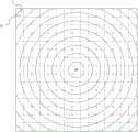
图3是本发明的汇聚超材料每一片层的折射率分布示意图;Fig. 3 is a schematic diagram of the refractive index distribution of each layer of the converging metamaterial of the present invention;
图4是本发明的一种汇聚超材料的结构示意图;Fig. 4 is a schematic structural view of a converging metamaterial of the present invention;
图5是本发明的另一种汇聚超材料的结构示意图;Fig. 5 is a structural schematic diagram of another converging metamaterial of the present invention;
图6是本发明的发散超材料每一片层的折射率分布示意图;Fig. 6 is a schematic diagram of the refractive index distribution of each sheet of the divergent metamaterial of the present invention;
图7是本发明的一种发散超材料的结构示意图;Fig. 7 is a structural schematic diagram of a divergent metamaterial of the present invention;
图8是本发明的另一种发散超材料的结构示意图;Figure 8 is a schematic structural view of another divergent metamaterial of the present invention;
图9是本发明的偏折超材料每一片层的折射率分布示意图;Fig. 9 is a schematic diagram of the refractive index distribution of each layer of the deflection metamaterial of the present invention;
图10是本发明的一种偏折超材料的结构示意图;Fig. 10 is a schematic structural view of a deflection metamaterial of the present invention;
图11是本发明的另一种偏折超材料的结构示意图。Fig. 11 is a schematic structural diagram of another deflection metamaterial of the present invention.
具体实施方式Detailed ways
如图1及图2所示,本发明提供了一种阵列式超材料天线100,所述天线100由多个超材料200组成,每一超材料200均由至少一个片层组成,每一片层包括片状的基材以及设置在基材上的多个人造孔结构。这里的片层是一个人为的概念,即为了方便描述,人为地将整个超材料划分为多个片层,每一片层的厚度方向上只有一个超材料单元。因此,不能机械地理解为每一片层是一个独立的部分,本发明中,超材料200可以是,例如通过注塑形成的一个整体结构,也可以是多片独立的片层贴合在一起形成的结构。所述每一基材分成多个相同的基材单元V,每一基材单元V与其上的人造孔结构12构成一个超材料单元D。每一基材单元D可以是完全相同的方块,可以是立方体,也可是长方体,每一基材单元V的长、宽、高体积不大于入射电磁波波长的五分之一(通常为入射电磁波波长的十分之一),以使得整个超材料对电磁波具有连续的电场和/或磁场响应。优选情况下,所述基材单元V为边长是入射电磁波波长十分之一的立方体。As shown in Figures 1 and 2, the present invention provides an
本发明的阵列式超材料天线还可以包括如图1所示的发射天线300,发射天线为常规的发射天线,用于产生和发射电磁波,并无特别之处。The arrayed metamaterial antenna of the present invention may also include a transmitting
本发明中,所述超材料的基材由陶瓷材料、高分子材料、铁电材料、铁氧材料或铁磁材料等制得。高分子材料可选用的有聚四氟乙烯、环氧树脂、F4B复合材料、FR-4复合材料等。例如,聚四氟乙烯的电绝缘性非常好,因此不会对电磁波的电场产生干扰,并且具有优良的化学稳定性、耐腐蚀性,使用寿命长。In the present invention, the base material of the metamaterial is made of ceramic material, polymer material, ferroelectric material, ferrite material or ferromagnetic material. Polymer materials can be selected from polytetrafluoroethylene, epoxy resin, F4B composite material, FR-4 composite material, etc. For example, polytetrafluoroethylene has very good electrical insulation, so it will not interfere with the electric field of electromagnetic waves, and has excellent chemical stability, corrosion resistance, and long service life.
本发明中,所述人造孔结构可以通过高温烧结、注塑、冲压或数控打孔的方式形成在基材上。当然对于不同材料的基材,人造孔结构的生成方式也会有所不同,例如,当选用陶瓷材料作为基材时,优选采用高温烧结的形式在基材上生成人造孔结构。当选用高分子材料作为基材时,例如聚四氟乙烯、环氧树脂,则优选采用注塑或冲压的形式在基材上生成人造孔结构。In the present invention, the artificial pore structure can be formed on the substrate by high temperature sintering, injection molding, stamping or numerical control drilling. Of course, for substrates of different materials, the ways of generating the artificial pore structure will also be different. For example, when ceramic materials are selected as the substrate, it is preferable to use high-temperature sintering to generate the artificial pore structure on the substrate. When a polymer material is selected as the base material, such as polytetrafluoroethylene or epoxy resin, it is preferable to form an artificial pore structure on the base material by injection molding or stamping.
本发明的所述人造孔结构可以是圆柱孔、圆锥孔、圆台孔、梯形孔或方形孔一种或组合。当然也可以是其它形式的孔。每一超材料单元D上的人造孔结构的形状根据不同的需要,可以相同,也可以不同。当然,为了更加容易加工制造,整个超材料,优选情况下,采用同一种形状的孔。如图2所示的圆柱孔。以下的描述中,均以圆柱孔为例,其它形式的孔原理类似。The artificial hole structure of the present invention may be one or a combination of cylindrical holes, conical holes, conical holes, trapezoidal holes or square holes. Of course, other types of holes are also possible. The shape of the artificial hole structure on each metamaterial unit D can be the same or different according to different needs. Of course, for easier processing and manufacturing, the entire metamaterial preferably uses holes of the same shape. Cylindrical holes as shown in Figure 2. In the following descriptions, cylindrical holes are taken as examples, and the principles of other types of holes are similar.
另外,图2所示的人造孔结构是贯穿超材料单元D的相对两个表面的,因此有利于填充介质材料。In addition, the artificial pore structure shown in FIG. 2 runs through the two opposite surfaces of the metamaterial unit D, so it is beneficial to fill the dielectric material.
我们知道,折射率可以表示电磁波传播方向的改变,已知折射率
本发明中,优选地,所述多个超材料为汇聚超材料、发散超材料及偏折超材料中的一种或其组合。即,多个超材料可以是同样功能的超材料,也可是各种功能的超材料的组合。其组合方式根据需要可以任意变化。当然上面只列举了三种功能的超材料,实际上利用类似的原理,还可以构造其它功能的超材料。In the present invention, preferably, the plurality of metamaterials are one or a combination of converging metamaterials, divergent metamaterials and deflection metamaterials. That is, the plurality of metamaterials may be metamaterials with the same function, or may be a combination of metamaterials with various functions. The combination thereof can be changed arbitrarily as required. Of course, the above only lists three kinds of functional metamaterials. In fact, similar principles can be used to construct metamaterials with other functions.
图1为本发明一个实施例的阵列式超材料天线,在本实施例中,阵列式超材料天线100由四个超材料200组成,这四个超材料200均是选自上述的三种功能的超材料,四个超材料可以功能相同,也可以不同,这个根据需要设定。Fig. 1 is an array type metamaterial antenna of an embodiment of the present invention, in this embodiment, array
另外,图1中,四个超材料是分开设置的,当然四个超材料也可以一体设置组成一个整体的超材料,四个超材料相当于整体超材料的四个局部。同时,四个超材料也还可是独立的间隔一定距离设置,也就是说,根据不同的需要本发明可以有不同的组合形式。In addition, in Figure 1, the four metamaterials are set separately. Of course, the four metamaterials can also be set together to form a whole metamaterial. The four metamaterials are equivalent to four parts of the whole metamaterial. At the same time, the four metamaterials can also be arranged independently at a certain distance, that is to say, the present invention can have different combinations according to different needs.
每一超材料可以由一个片层组成,也可以是由多个相互平行的片层堆叠形成。以下均以多个片层的结构来描述本发明。Each metamaterial can be composed of one sheet, or can be formed by stacking multiple parallel sheets. The present invention is described below with a multi-layer structure.
本发明的汇聚超材料每一片层的折射率分布如图3所示。所述汇聚超材料每一片层上的所有超材料单元D的折射率以片层的中心O为圆心呈圆形分布,处于同一半径上的超材料单元D其折射率相同,并且处于任一半径所在的直线方向上的多个超材料单元D的折射率均由外侧向片层中心依次增大。此处的圆形分布,既包括如图3中的完整的圆,也包括图3中四个角上的不完整的圆(圆弧)。The refractive index distribution of each layer of the converging metamaterial of the present invention is shown in FIG. 3 . The refractive indices of all the metamaterial units D on each sheet of the converging metamaterial are circularly distributed with the center O of the sheet as the center, and the refractive indices of the metamaterial units D on the same radius are the same, and they are at any radius The refractive indices of the multiple metamaterial units D in the direction of the straight line increase sequentially from the outside to the center of the sheet. The circular distribution here includes both complete circles as shown in Figure 3 and incomplete circles (arcs) at the four corners in Figure 3 .
此处半径指的是每一基材单元V的中点到片层中心的距离(片层中心位置的基材单元的中点O),此处的基材单元V的中点,指的基材单元V与中点O同一平面的一表面S的中点。The radius here refers to the distance from the midpoint of each substrate unit V to the center of the sheet (the midpoint O of the substrate unit at the center of the sheet), and the midpoint of the substrate unit V here refers to the base The midpoint of a surface S on which the material element V is on the same plane as the midpoint O.
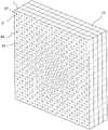
图4为汇聚超材料一种结构形式。在图4所示的汇聚超材料10中,每一片层11的多个人造孔结构12形状相同,均为圆柱形孔,且每一圆柱形孔的中轴线穿过相应的基材单元V的中点,所述多个人造孔结构12中填充有折射率大于基材13的介质14,处于同一半径上的的人造孔结构12其体积相同,并且处于任一半径所在的直线方向上的多个人造孔结构12的体积均由外侧向片层中心依次增大。由于人造孔结构中填充有折射率大于基材的介质,因此人造孔结构体积越大,则填充的介质越多,其对应的超材料单元的折射率越大,因此,通过此方式实现了图3所示的折射率分布。另外,优选地,每一片层12结构相同,以简化制作工艺。Figure 4 shows a structural form of a convergent metamaterial. In the converging
图5为汇聚超材料另一种结构形式。在图5所示的汇聚超材料20中,所述汇聚超材料20每一片层21的多个人造孔结构22形状相同,所述多个人造孔结构22中填充有折射率小于基材23的介质24,处于同一半径上的的人造孔结构22其体积相同,并且处于任一半径所在的直线方向上的多个人造孔结构22的体积均由外侧向片层中心依次减小。由于人造孔结构22中填充有折射率小于基材的介质24,因此人造孔结构体积越大,则填充的介质越多,其对应的超材料单元的折射率反而越小,因此,通过此方式也可以实现图3所示的折射率分布。另外,优选地,每一片层12结构相同,以简化制作工艺。Fig. 5 is another structural form of the converging metamaterial. In the converging metamaterial 20 shown in FIG. 5 , the multiple
当然,汇聚超材料并不限于上述两种形式,例如,每个人造孔结构可以分成若干个单元孔,通过每个基材单元上的单元孔的数量来控制每一超材料单元上的人造孔结构的体积也可以实现相同的目的。再例如,汇聚超材料可以是如下的形式,即,同一片层所有的人造孔结构体积相同,但是其填充的介质的折射率呈圆形分布,即片层中心的超材料单元其填充的介质的折射率最大,处于同一半径上的的人造孔结构内填充的介质的折射率相同,并且处于任一半径所在的直线方向上的多个人造孔结构中填充的介质的折射率均由外侧向片层中心依次增大。Of course, converging metamaterials are not limited to the above two forms. For example, each artificial pore structure can be divided into several unit pores, and the artificial pores on each metamaterial unit can be controlled by the number of unit pores on each substrate unit. The volume of the structure can also serve the same purpose. As another example, converging metamaterials can be in the form that all the artificial pore structures in the same sheet have the same volume, but the refractive index of the medium they fill has a circular distribution, that is, the medium filled by the metamaterial unit in the center of the sheet The refractive index is the largest, the refractive index of the medium filled in the artificial pore structure on the same radius is the same, and the refractive index of the medium filled in the multiple artificial pore structures on the straight line direction of any radius is from the outside to the The center of the lamella increases sequentially.
本发明的发散超材料每一片层的折射率分布如图6所示。所述发散超材料每一片层上的所有超材料单元D的折射率以片层的中心O为圆心呈圆形分布,处于同一半径上的超材料单元D其折射率相同,并且处于任一半径所在的直线方向上的多个超材料单元D的折射率均由外侧向片层中心依次增大。此处的圆形分布,既包括如图6中的完整的圆,也包括图6中四个角上的不完整的圆(圆弧)。The refractive index distribution of each layer of the divergent metamaterial of the present invention is shown in FIG. 6 . The refractive index of all metamaterial units D on each sheet of the divergent metamaterial is distributed circularly with the center O of the sheet as the center of the circle, and the refractive indices of the metamaterial units D on the same radius are the same, and at any radius The refractive indices of the multiple metamaterial units D in the direction of the straight line increase sequentially from the outside to the center of the sheet. The circular distribution here includes both complete circles as shown in FIG. 6 and incomplete circles (arcs) at the four corners in FIG. 6 .
此处半径指的是每一基材单元V的中点到片层中心的距离(片层中心位置的基材单元的中点O),此处的基材单元V的中点,指的基材单元一表面S的中点。The radius here refers to the distance from the midpoint of each substrate unit V to the center of the sheet (the midpoint O of the substrate unit at the center of the sheet), and the midpoint of the substrate unit V here refers to the base The midpoint of a surface S of the material element.
图7为发散超材料一种结构形式。在图7所示的发散超材料30中,每一片层31的多个人造孔结构32形状相同,均为圆柱形孔,且每一圆柱形孔的中轴线穿过相应的基材单元V的中点,所述多个人造孔结构32中填充有折射率大于基材33的介质34,处于同一半径上的的人造孔结构32其体积相同,并且处于任一半径所在的直线方向上的多个人造孔结构32的体积均由外侧向片层中心依次减小。由于人造孔结构中填充有折射率大于基材的介质,因此人造孔结构体积越大,则填充的介质越多,其对应的超材料单元的折射率越大,因此,通过此方式实现了图6所示的折射率分布。另外,优选地,每一片层12结构相同,以简化制作工艺。Fig. 7 shows a structural form of a divergent metamaterial. In the divergent metamaterial 30 shown in FIG. 7 , the multiple
图8为汇聚超材料另一种结构形式。在图8所示的发散超材料40中,所述发散超材料40每一片层41的多个人造孔结构42形状相同,所述多个人造孔结构42中填充有折射率小于基材43的介质44,处于同一半径上的的人造孔结构42其体积相同,并且处于任一半径所在的直线方向上的多个人造孔结构42的体积均由外侧向片层中心依次增大。由于人造孔结构42中填充有折射率小于基材的介质44,因此人造孔结构体积越大,则填充的介质越多,其对应的超材料单元的折射率反而越小,因此,通过此方式也可以实现图6所示的折射率分布。另外,优选地,每一片层12结构相同,以简化制作工艺。Fig. 8 is another structural form of the converging metamaterial. In the divergent metamaterial 40 shown in FIG. 8 , the multiple
当然,发散超材料并不限于上述两种形式,例如,每个人造孔结构可以分成若干个单元孔,通过每个基材单元上的单元孔的数量来控制每一超材料单元上的人造孔结构的体积也可以实现相同的目的。再例如,汇聚超材料可以是如下的形式,即,同一片层所有的人造孔结构体积相同,但是其填充的介质的折射率呈圆形分布,即片层中心的超材料单元其填充的介质的折射率最小,处于同一半径上的的人造孔结构内填充的介质的折射率相同,并且处于任一半径所在的直线方向上的多个人造孔结构中填充的介质的折射率均由外侧向片层中心依次减小。Of course, divergent metamaterials are not limited to the above two forms. For example, each artificial pore structure can be divided into several unit pores, and the artificial pores on each metamaterial unit can be controlled by the number of unit pores on each substrate unit. The volume of the structure can also serve the same purpose. As another example, converging metamaterials can be in the form that all the artificial pore structures in the same sheet have the same volume, but the refractive index of the medium they fill has a circular distribution, that is, the medium filled by the metamaterial unit in the center of the sheet The refractive index is the smallest, the refractive index of the medium filled in the artificial pore structure on the same radius is the same, and the refractive index of the medium filled in multiple artificial pore structures in the straight line direction of any radius is from the outside to the The center of the sheet decreases successively.
本发明的偏折超材料每一片层的折射率分布如图9所示。所述偏折超材料每一片层上的所有超材料单元D呈矩形阵列分布,同一行或同一列的多个超材料单元其折射率由一端向另一端依次减小。如图9中,同一行的折射率相同,每一行的折射率从n1一直增大到n15;即n1<n2......<n14<n15。The refractive index distribution of each layer of the deflection metamaterial of the present invention is shown in FIG. 9 . All the metamaterial units D on each sheet of the deflection metamaterial are distributed in a rectangular array, and the refractive index of multiple metamaterial units in the same row or column decreases sequentially from one end to the other end. As shown in FIG. 9 , the same row has the same refractive index, and the refractive index of each row increases from n1 to n15; that is, n1<n2...<n14<n15.
图10为偏折超材料一种结构形式。在图10所示的偏折超材料50中,所述偏折超材料50每一片层51的多个人造孔结构52形状相同,所述多个人造孔结构52中填充有折射率大于基材53的介质54,处于同一行的多个人造孔结构52的体积由左端向右端依次增大。由于人造孔结构中填充有折射率大于基材的介质,因此人造孔结构体积越大,则填充的介质越多,其对应的超材料单元的折射率越大,因此,通过此方式实现了图9所示的折射率分布。另外,优选地,每一片层51的结构相同,以简化制作工艺。Figure 10 shows a structural form of the deflection metamaterial. In the deflection metamaterial 50 shown in FIG. 10 , the multiple
图11为偏折超材料另一种结构形式。在图11所示的偏折超材料60中,所述偏折超材料60每一片层61的多个人造孔结构62形状相同,所述多个人造孔结构62中填充有折射率小于基材63的介质64,处于同一行的多个人造孔结构62的体积由左端向右端依次减小。由于人造孔结构中填充有折射率小于基材的介质,因此人造孔结构体积越大,则填充的介质越多,其对应的超材料单元的折射率越小,因此,通过此方式也可以实现图9所示的折射率分布。另外,优选地,每一片层61的结构相同,以简化制作工艺。Fig. 11 shows another structural form of the deflection metamaterial. In the deflection metamaterial 60 shown in FIG. 11 , the multiple artificial hole structures 62 of each
当然,偏折超材料并不限于上述两种形式,例如,每个人造孔结构可以分成若干个单元孔,通过每个基材单元上的单元孔的数量来控制每一超材料单元上的人造孔结构的体积也可以实现相同的目的。并且通过将偏折超材料旋转可以实现不同的偏折效果,例如,当从上端到下端折射率依次减小时,电磁波向上偏折;当从上端到下端折射率依次增大时,电磁波向下偏折;当从左端到右端折射率依次增大时,电磁波向右偏折;当从左端到右端折射率依次减小时,电磁波向左偏折。这就是说,同一个偏折超材料,可以以不同的放置,实现电磁波向不同的方向偏折。无需做多个偏折超材料。Of course, deflection metamaterials are not limited to the above two forms. For example, each artificial pore structure can be divided into several unit pores, and the artificial pore structure on each metamaterial unit is controlled by the number of unit pores on each substrate unit. The volume of the pore structure can also serve the same purpose. And by rotating the deflection metamaterial, different deflection effects can be achieved. For example, when the refractive index decreases from the upper end to the lower end, the electromagnetic wave is deflected upward; when the refractive index increases from the upper end to the lower end, the electromagnetic wave is deflected downward. Refraction; when the refractive index increases from the left end to the right end, the electromagnetic wave is deflected to the right; when the refractive index decreases from the left end to the right end, the electromagnetic wave is deflected to the left. That is to say, the same deflecting metamaterial can be placed differently to deflect electromagnetic waves in different directions. No need to make multiple deflection metamaterials.
上面结合附图对本发明的实施例进行了描述,但是本发明并不局限于上述的具体实施方式,上述的具体实施方式仅仅是示意性的,而不是限制性的,本领域的普通技术人员在本发明的启示下,在不脱离本发明宗旨和权利要求所保护的范围情况下,还可做出很多形式,这些均属于本发明的保护之内。Embodiments of the present invention have been described above in conjunction with the accompanying drawings, but the present invention is not limited to the above-mentioned specific implementations, and the above-mentioned specific implementations are only illustrative, rather than restrictive, and those of ordinary skill in the art will Under the enlightenment of the present invention, many forms can also be made without departing from the gist of the present invention and the protection scope of the claims, and these all belong to the protection of the present invention.
Claims (14)
Translated fromChinesePriority Applications (1)
| Application Number | Priority Date | Filing Date | Title |
|---|---|---|---|
| CN2011101810002ACN102800985A (en) | 2011-06-30 | 2011-06-30 | Array metamaterial antenna |
Applications Claiming Priority (1)
| Application Number | Priority Date | Filing Date | Title |
|---|---|---|---|
| CN2011101810002ACN102800985A (en) | 2011-06-30 | 2011-06-30 | Array metamaterial antenna |
Publications (1)
| Publication Number | Publication Date |
|---|---|
| CN102800985Atrue CN102800985A (en) | 2012-11-28 |
Family
ID=47200011
Family Applications (1)
| Application Number | Title | Priority Date | Filing Date |
|---|---|---|---|
| CN2011101810002APendingCN102800985A (en) | 2011-06-30 | 2011-06-30 | Array metamaterial antenna |
Country Status (1)
| Country | Link |
|---|---|
| CN (1) | CN102800985A (en) |
Cited By (1)
| Publication number | Priority date | Publication date | Assignee | Title |
|---|---|---|---|---|
| CN105742824A (en)* | 2016-04-13 | 2016-07-06 | 中国电子科技集团公司第五十四研究所 | Low-profile lens antenna capable of realizing wide-angle scanning |
Citations (4)
| Publication number | Priority date | Publication date | Assignee | Title |
|---|---|---|---|---|
| CN101699659A (en)* | 2009-11-04 | 2010-04-28 | 东南大学 | Lens antenna |
| CN201450116U (en)* | 2009-07-01 | 2010-05-05 | 东南大学 | Lens antenna with high frequency bandwidth gain and good directivity |
| CN101867094A (en)* | 2010-05-02 | 2010-10-20 | 兰州大学 | A Focused Panel Antenna |
| US20110069377A1 (en)* | 2009-09-18 | 2011-03-24 | Toyota Motor Engineering & Manufacturing North America, Inc. | Planar gradient index optical metamaterials |
- 2011
- 2011-06-30CNCN2011101810002Apatent/CN102800985A/enactivePending
Patent Citations (4)
| Publication number | Priority date | Publication date | Assignee | Title |
|---|---|---|---|---|
| CN201450116U (en)* | 2009-07-01 | 2010-05-05 | 东南大学 | Lens antenna with high frequency bandwidth gain and good directivity |
| US20110069377A1 (en)* | 2009-09-18 | 2011-03-24 | Toyota Motor Engineering & Manufacturing North America, Inc. | Planar gradient index optical metamaterials |
| CN101699659A (en)* | 2009-11-04 | 2010-04-28 | 东南大学 | Lens antenna |
| CN101867094A (en)* | 2010-05-02 | 2010-10-20 | 兰州大学 | A Focused Panel Antenna |
Cited By (1)
| Publication number | Priority date | Publication date | Assignee | Title |
|---|---|---|---|---|
| CN105742824A (en)* | 2016-04-13 | 2016-07-06 | 中国电子科技集团公司第五十四研究所 | Low-profile lens antenna capable of realizing wide-angle scanning |
Similar Documents
| Publication | Publication Date | Title |
|---|---|---|
| US8421550B2 (en) | Impedance matching component and hybrid wave-absorbing material | |
| CN103036046B (en) | A kind of feedback type satellite tv antenna and satellite television receiving system thereof | |
| US10700438B2 (en) | Guide element for an antenna and method for producing such guide element | |
| CN102760954A (en) | Metamaterial capable of deflecting electromagnetic wave | |
| CN102738594B (en) | A Metamaterial Directional Antenna | |
| CN103094701B (en) | A kind of flat-plate lens and there is the lens antenna of these lens | |
| CN102480044B (en) | Base station antenna | |
| CN102683892B (en) | Metamaterial electromagnetic lens antenna | |
| CN102480049B (en) | Base station antenna | |
| CN102480045B (en) | Base station antenna | |
| CN102480048A (en) | Base station antenna | |
| CN102480056B (en) | Base station antenna | |
| CN102800985A (en) | Array metamaterial antenna | |
| CN102570044B (en) | base station antenna | |
| CN102694232B (en) | Array-type metamaterial antenna | |
| CN102683893B (en) | Antenna | |
| CN102800974B (en) | A base station antenna | |
| CN102904051B (en) | Base station antenna | |
| CN102480043A (en) | Antenna of base station | |
| CN102480041B (en) | Feed-forward type satellite television antenna and satellite television receiving system thereof | |
| CN103367906B (en) | Directional spreading antenna housing and directional antenna system | |
| CN103094711B (en) | A kind of lens antenna | |
| CN103036064A (en) | Cassegrain type metamaterial antenna | |
| CN102780095B (en) | High-directivity antenna | |
| CN102790278A (en) | Directional antenna |
Legal Events
| Date | Code | Title | Description |
|---|---|---|---|
| C06 | Publication | ||
| PB01 | Publication | ||
| C10 | Entry into substantive examination | ||
| SE01 | Entry into force of request for substantive examination | ||
| C12 | Rejection of a patent application after its publication | ||
| RJ01 | Rejection of invention patent application after publication | Application publication date:20121128 |