CN102800953A - Indirect feed type omnidirectional printed antenna with radiant load - Google Patents
Indirect feed type omnidirectional printed antenna with radiant loadDownload PDFInfo
- Publication number
- CN102800953A CN102800953ACN2012102791037ACN201210279103ACN102800953ACN 102800953 ACN102800953 ACN 102800953ACN 2012102791037 ACN2012102791037 ACN 2012102791037ACN 201210279103 ACN201210279103 ACN 201210279103ACN 102800953 ACN102800953 ACN 102800953A
- Authority
- CN
- China
- Prior art keywords
- coplanar waveguide
- feeder
- antenna
- units
- feeding units
- Prior art date
- Legal status (The legal status is an assumption and is not a legal conclusion. Google has not performed a legal analysis and makes no representation as to the accuracy of the status listed.)
- Granted
Links
Images


Landscapes
- Details Of Aerials (AREA)
Abstract
Translated fromChinese
Description
Translated fromChinese技术领域technical field
本发明涉及一种印刷天线,具体涉及一种带有辐射型负载的间接馈电型全向印刷天线。The invention relates to a printing antenna, in particular to an indirect feeding omnidirectional printing antenna with a radiation load.
背景技术Background technique
印刷型天线是一种采用现代印制电路板技术制作的天线,全向天线是一种在水平面内辐射特性基本没有差异,而在垂直面内具有定向辐射性的天线,即在水平方向图上表现为360°均匀辐射,也就是平常所说的无方向性。全向天线发展至今,结构形式上产生了多样化的改变,从最初的单极子、偶极子、双锥、螺旋天线到微带、智能天线等,而实现方式上主要有并馈和串馈两种方式。在一点对多点的基站对终端的通信和卫星通信系统等一些专用通信系统中有广泛的应用。The printed antenna is an antenna made with modern printed circuit board technology. The omnidirectional antenna is an antenna that has basically no difference in radiation characteristics in the horizontal plane, but has directional radiation in the vertical plane, that is, on the horizontal pattern. It is manifested as 360° uniform radiation, which is commonly referred to as non-directional. Since the development of omnidirectional antennas, there have been various changes in structural forms, from the initial monopole, dipole, biconical, and helical antennas to microstrip, smart antennas, etc., and the implementation methods mainly include parallel feed and series antennas. Feed two ways. It is widely used in some special communication systems such as point-to-multipoint base station-to-terminal communication and satellite communication system.
一般以全向增益超过4dB为标准,这样可保证波束较宽。因此需要通过合理的设计保证天线在单位尺寸上产生较高的增益,现有的研究主要集中在:Generally, the omnidirectional gain exceeds 4dB as the standard, which can ensure a wider beam. Therefore, it is necessary to ensure that the antenna has a higher gain per unit size through a reasonable design. Existing research mainly focuses on:
(1)是一系列异形振子,虽然能够实现宽带,但会发生方向图分裂,全向性较差。(1) It is a series of special-shaped oscillators. Although it can achieve broadband, it will split the pattern and have poor omnidirectionality.
(2)是同轴共线交叉馈电振子天线(COCO Antenna),虽然能够实现高增益和全向性,但是由于终端为短路器,整个天线为谐振式结构,导致带宽较窄。(2) It is a coaxial collinear cross-feed dipole antenna (COCO Antenna). Although it can achieve high gain and omnidirectionality, because the terminal is a short circuit, the entire antenna is a resonant structure, resulting in a narrow bandwidth.
(3)上述的全向高增益天线普遍具有带宽窄和单位长度产生的增益较低等特点,而后者不利于天线的小型化。(3) The above-mentioned omnidirectional high-gain antenna generally has the characteristics of narrow bandwidth and low gain per unit length, and the latter is not conducive to the miniaturization of the antenna.
因此如何在保证全向性较好的情况下尽可能展宽带宽并同时提高增益,是研究的热点问题。Therefore, how to widen the bandwidth as much as possible and increase the gain while ensuring good omnidirectionality is a hot research issue.
发明内容Contents of the invention
本发明的目的是提供一种带有辐射型负载的间接馈电型全向印刷天线,以解决目前的天线无法同时满足全向好、带宽较宽且增益较高的问题。The purpose of the present invention is to provide an indirect-feed omnidirectional printed antenna with a radiating load, so as to solve the problem that the current antenna cannot simultaneously satisfy the requirements of good omnidirectionality, wide bandwidth and high gain.
本发明为解决上述技术问题采取的技术方案是:所述天线包括介质板、辐射型终端负载、交叉中心馈线、共面波导中心馈线、、第一接地板、第二接地板、多个第一共面波导馈电单元、多个第二共面波导馈电单元、多个第三共面波导馈电单元和多个第四共面波导馈电单元,介质板上印刷有辐射型终端负载、交叉中心馈线、共面波导中心馈线、多个第一共面波导馈电单元、多个第二共面波导馈电单元、多个第三共面波导馈电单元和多个第四共面波导馈电单元,共面波导中心馈线的上端与辐射型终端负载连接,共面波导中心馈线与交叉中心馈线平行设置,第一共面波导馈电单元、第二共面波导馈电单元、第三共面波导馈电单元和第四共面波导馈电单元均为长方形,共面波导中心馈线的外侧壁上间隔设置多个第一共面波导馈电单元和第一接地板,第一接地板位于共面波导中心馈线的最底端,第三共面波导馈电单元位于相邻两个第一共面波导馈电单元之间,第三共面波导馈电单元与共面波导中心馈线之间的距离为0.4-1.2mm,交叉中心馈线的外侧壁上间隔设置多个第二共面波导馈电单元和第二接地板,第二接地板位于交叉中心馈线的最底端,第四共面波导馈电单元位于相邻两个第二共面波导馈电单元之间,第四共面波导馈电单元与交叉中心馈线之间的距离为0.4-1.2mm。The technical solution adopted by the present invention to solve the above technical problems is: the antenna includes a dielectric plate, a radial terminal load, a cross center feeder, a coplanar waveguide center feeder, a first ground plate, a second ground plate, a plurality of first A coplanar waveguide feeding unit, a plurality of second coplanar waveguide feeding units, a plurality of third coplanar waveguide feeding units and a plurality of fourth coplanar waveguide feeding units, the dielectric plate is printed with a radial terminal load, Cross center feeder, coplanar waveguide center feeder, multiple first coplanar waveguide feed units, multiple second coplanar waveguide feed units, multiple third coplanar waveguide feed units, and multiple fourth coplanar waveguide feed units The feeder unit, the upper end of the coplanar waveguide center feeder is connected to the radial terminal load, the coplanar waveguide center feeder and the cross center feeder are arranged in parallel, the first coplanar waveguide feeder unit, the second coplanar waveguide feeder unit, the third Both the coplanar waveguide feeding unit and the fourth coplanar waveguide feeding unit are rectangular, and a plurality of first coplanar waveguide feeding units and first grounding plates are arranged at intervals on the outer wall of the coplanar waveguide central feeder line, and the first grounding plate Located at the bottom end of the coplanar waveguide center feeder, the third coplanar waveguide feeder unit is located between two adjacent first coplanar waveguide feeder units, and between the third coplanar waveguide feeder unit and the coplanar waveguide center feeder line The distance between them is 0.4-1.2mm. A plurality of second coplanar waveguide feed units and second grounding plates are arranged at intervals on the outer wall of the crossing center feeder. The second grounding plate is located at the bottom end of the crossing center feeder. The fourth coplanar waveguide The waveguide feeding unit is located between two adjacent second coplanar waveguide feeding units, and the distance between the fourth coplanar waveguide feeding unit and the cross central feeding line is 0.4-1.2mm.
本发明具有以下有益效果:本发明与传统COCO天线有相似之处,只是从空间立体结构变成了平面结构,也使其从封闭结构变成了开放式的结构。当电流从底端馈入到馈线上时,电流就沿着交叉相连的传输线流动,在传输线上建立起电流分布,而电流到终端(顶端)时,遇到了一个辐射型终端负载,也会在辐射型终端负载上建立起电流分布,由于辐射型终端负载和与之相连的共面波导中心馈线以及接地板就构成了一个三角形单极天线,其上的电流本身可以辐射到自由空间,所以整个天线的终端相当于连接了一个匹配负载,在三角形单极天线的工作频带内,共面波导中交叉馈线上的电流为行波电流。这是本发明的天线与传统COCO天线的重要差别,传统COCO天线上的电流全部为驻波电流,这个差别使本发明天线的带宽要比传统的COCO天线要宽。本天线采用印刷形式,便于通信电路集成,符合小型化的要求,还具有成本低、重量轻、结构简单及容易实现等诸多优点,具有广阔的应用前景。本发明所提出的天线是单面印刷电路,在大批量生产中可以节约成本40-50%,会产生显著地经济效益;另外,单面板与双面板尤其是带有过孔的双面板相比,将显著提高稳定性。The present invention has the following beneficial effects: the present invention is similar to the traditional COCO antenna, except that it changes from a three-dimensional structure to a planar structure, and also changes it from a closed structure to an open structure. When the current is fed into the feeder from the bottom end, the current flows along the cross-connected transmission line, and a current distribution is established on the transmission line, and when the current reaches the terminal (top), it encounters a radial terminal load, and also in The current distribution is established on the radial terminal load. Since the radial terminal load and the coplanar waveguide central feeder connected to it and the ground plate constitute a triangular monopole antenna, the current on it can radiate to free space, so the whole The terminal of the antenna is equivalent to connecting a matching load. In the working frequency band of the triangular monopole antenna, the current on the cross feeder in the coplanar waveguide is a traveling wave current. This is an important difference between the antenna of the present invention and the traditional COCO antenna. The currents on the traditional COCO antenna are all standing wave currents. This difference makes the bandwidth of the antenna of the present invention wider than that of the traditional COCO antenna. The antenna adopts a printed form, which is convenient for communication circuit integration and meets the requirements of miniaturization. It also has many advantages such as low cost, light weight, simple structure and easy realization, and has broad application prospects. The antenna proposed by the present invention is a single-sided printed circuit, which can save 40-50% of the cost in mass production, and will produce significant economic benefits; , will significantly improve stability.
附图说明Description of drawings
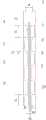
图1是等腰梯形辐射型终端负载天线的结构主视图,图2是图1的侧视图,图3是本发明的组合形辐射型终端负载天线的结构主视图,图4是本发明的圆形辐射型终端负载天线的结构主视图,图5是具体实施方式三中的天线反射系数与频率的关系图,图6是具体实施方式三的天线在典型频点4.8GHz的E面和H面方向图,图7是传统的同轴共线交叉馈电振子天线演变为本发明天线的过程示意图。Fig. 1 is the structure front view of isosceles trapezoidal radiation type terminal load antenna, Fig. 2 is the side view of Fig. 1, Fig. 3 is the structure front view of combined shape radiation type terminal load antenna of the present invention, Fig. 4 is the circle of the present invention The front view of the structure of the shaped radiation type terminal load antenna, Fig. 5 is the relationship diagram between the reflection coefficient of the antenna and the frequency in the
具体实施方式Detailed ways
具体实施方式一:结合图1和图2说明本实施方式,本实施方式的天线包括介质板1、辐射型终端负载2、交叉中心馈线3、共面波导中心馈线4、第一接地板9、第二接地板10、多个第一共面波导馈电单元5、多个第二共面波导馈电单元6、多个第三共面波导馈电单元7和多个第四共面波导馈电单元8,介质板1上印刷有辐射型终端负载2、交叉中心馈线3、共面波导中心馈线4、多个第一共面波导馈电单元5、多个第二共面波导馈电单元6、多个第三共面波导馈电单元7和多个第四共面波导馈电单元8,共面波导中心馈线4的上端与辐射型终端负载2连接,共面波导中心馈线4与交叉中心馈线3平行设置,第一共面波导馈电单元5、第二共面波导馈电单元6、第三共面波导馈电单元7和第四共面波导馈电单元8均为长方形,共面波导中心馈线4的外侧壁上间隔设置多个第一共面波导馈电单元5和第一接地板9,第一接地板9位于共面波导中心馈线4的最底端,第三共面波导馈电单元7位于相邻两个第一共面波导馈电单元5之间,第三共面波导馈电单元7与共面波导中心馈线4之间的距离为0.4-1.2mm,交叉中心馈线3的外侧壁上间隔设置多个第二共面波导馈电单元6和第二接地板10,第二接地板10位于交叉中心馈线3的最底端,*第四共面波导馈电单元8位于相邻两个第二共面波导馈电单元6之间,第四共面波导馈电单元8与交叉中心馈线3之间的距离为0.4-1.2mm。Specific Embodiment 1: This embodiment is described in conjunction with FIG. 1 and FIG. 2. The antenna in this embodiment includes a
本天线的介质板采用相对介电常数为4.4的介质材料,是市面上容易得到的材料,价格比较低廉。The dielectric plate of the antenna adopts a dielectric material with a relative permittivity of 4.4, which is easily available on the market and is relatively cheap.
所述的CPW交叉耦合馈电印刷天线置于FR4环氧树脂板上,该介质板材料的介电常数εr=4.4,本印刷天线馈电处使用共面波导馈电,介质板1的长度为L、厚度为h,辐射型终端负载2的高度为l1,、厚度t,第一共面波导馈电单元5、第二共面波导馈电单元6、第三共面波导馈电单元7和第四共面波导馈电单元8长度均为l2,第一共面波导馈电单元5和第二共面波导馈电单元6之间的距离为l3,l2和l3用于改变天线的通带范围,第一接地板9和第二接地板10的长度为l4、宽度为w2,其中接地板既是馈线一部分,也是辐射单元节;The CPW cross-coupled feeding printed antenna is placed on the FR4 epoxy resin board, and the dielectric constant εr of the dielectric board material is 4.4. The feeding place of the printed antenna uses coplanar waveguide feeding, and the length of the
交叉中心馈线3的宽度为w1,w1用于改善天线的全向性,优选距离为0.8-1.2mm,交叉中心馈线3与共面波导中心馈线4之间的距离为g;The width of the
共面波导中心馈线4的宽度为w1与交叉中心馈线3与共面波导中心馈线4之间的距离g的比例用于调整印刷引向天线的阻抗。当w1/g≈2时,输入阻抗基本与50Ω匹配。The ratio of the width of the coplanar waveguide
具体实施方式二:结合图1-图4说明本实施方式,本实施方式的辐射型终端负载2为等腰梯形、组合形或圆形,其中组合形由长方形与弓形构成,长方形的长边与弓形的弦长度相等,等腰梯形的上底长度为d=5mm,下底长度等于共面波导中心馈线4的宽度为w1,等腰梯形的高度为l1;组合形的长方形长边长度为d=17.5mm,短边长度为9.0mm,弓形的高度为4.0mm;圆形的直径d=16mm,其顶端紧贴介质板上边缘。其它实施方式与具体实施方式一相同。Specific Embodiment 2: This embodiment is described with reference to FIGS. 1-4 . The
具体实施方式三:结合图5-图7说明本实施方式,本实施方式馈电处使用共面波导馈电,辐射型终端负载2为等腰梯形。所述的共面波导交叉耦合馈电印刷天线置于介质板上,该介质板材料的介电常数εr=4.4;辐射型终端负载2的上边的宽度为d、下边的宽度与共面波导中心馈线4的宽度相同,天线的尺寸为:h=0.5mm,t=0.1mm,l1=15mm,l2=17.25mm,l3=3mm,l4=17.25mm,g=0.4mm,w1=0.8mm,w2=5.8mm,L=133.5mm。Specific implementation mode 3: This implementation mode is described with reference to FIG. 5-FIG. 7 . In this implementation mode, a coplanar waveguide is used for power feeding, and the
根据上述要求的尺寸制作了天线的实物并进行了测试。结果表明,天线在4.3GHz-5.1GHz的频带内反射系数低于-10dB,相对带宽为17%。所设计的天线与COCO天线有相似之处,只是从空间立体结构变成了平面结构,也使其从封闭结构变成了开放式的结构,如图7所示。当电流从底端馈入到馈线上时,电流就沿着交叉相连的传输线流动,在传输线上建立起电流分布,而电流到终端(顶端)时,遇到了一个辐射型终端负载2,也会在辐射型终端负载2上建立起电流分布,由于辐射型终端负载2和与之相连的共面波导金属线以及地板就构成了一个三角形单极天线,其上的电流本身可以辐射到自由空间,所以整个天线的终端相当于连接了一个匹配负载,在三角形单极天线的工作频带内,共面波导交叉馈线上的电流为行波电流。这是本文设计的开放式的共面波导交叉馈电天线与传统COCO天线的重要差别,传统COCO天线上的电流全部为驻波电流,这个差别使共面波导交叉馈电天线的带宽要比传统的COCO天线要宽。该行波电流通过耦合在共面波导的第二接地板上产生了电流分布,这部分电流为驻波电流,其谐振频率要受到接地板尺寸的限制。According to the size required above, the actual antenna was made and tested. The results show that the reflection coefficient of the antenna is lower than -10dB in the frequency band of 4.3GHz-5.1GHz, and the relative bandwidth is 17%. The designed antenna is similar to the COCO antenna, except that it changes from a three-dimensional structure to a planar structure, and also changes it from a closed structure to an open structure, as shown in Figure 7. When the current is fed into the feeder from the bottom end, the current flows along the cross-connected transmission line to establish a current distribution on the transmission line, and when the current reaches the terminal (top), it encounters a
从图6的天线方向图可以看出,天线在C波段所应用的典型频率4.8GHz处的H面具有很好的全向性,最大辐射方向增益大于7.0dB。结合天线尺寸以及增益的值,即本天线物理长度为133.5mm,工作波长为62.5mm(4.8GHz),得到的单位电长度产生的增益为3.3dB,说明了本项发明在天线尺寸、带宽、全向性和增益等指标上获得了良好的结合。From the antenna pattern in Figure 6, it can be seen that the H-plane of the antenna at the typical frequency of 4.8GHz used in the C-band has good omnidirectionality, and the maximum radiation direction gain is greater than 7.0dB. Combined with the antenna size and the value of the gain, that is, the physical length of the antenna is 133.5mm, and the operating wavelength is 62.5mm (4.8GHz), the gain generated by the unit electrical length obtained is 3.3dB, which shows that the present invention has advantages in antenna size, bandwidth, A good combination of indicators such as omnidirectionality and gain has been achieved.
本发明天线采用印刷形式,便于通信电路集成,符合小型化的要求,还具有成本低、重量轻、结构简单容易实现等诸多优点,具有广阔的应用前景。本发明所提出的天线是单面印刷电路,在大批量生产中可以节约成本40-50%,会产生显著地经济效益;单面板与双面板尤其是带有过孔的双面板相比,将显著提高稳定性。The antenna of the invention adopts a printed form, which is convenient for communication circuit integration, meets the requirements of miniaturization, and has many advantages such as low cost, light weight, simple structure and easy realization, etc., and has broad application prospects. The antenna proposed by the present invention is a single-sided printed circuit, which can save 40-50% of the cost in mass production, and will produce significant economic benefits; Significantly improved stability.
Claims (2)
Translated fromChinesePriority Applications (1)
| Application Number | Priority Date | Filing Date | Title |
|---|---|---|---|
| CN201210279103.7ACN102800953B (en) | 2012-08-07 | 2012-08-07 | Indirect feed type omnidirectional printed antenna with radiant load |
Applications Claiming Priority (1)
| Application Number | Priority Date | Filing Date | Title |
|---|---|---|---|
| CN201210279103.7ACN102800953B (en) | 2012-08-07 | 2012-08-07 | Indirect feed type omnidirectional printed antenna with radiant load |
Publications (2)
| Publication Number | Publication Date |
|---|---|
| CN102800953Atrue CN102800953A (en) | 2012-11-28 |
| CN102800953B CN102800953B (en) | 2014-07-23 |
Family
ID=47199979
Family Applications (1)
| Application Number | Title | Priority Date | Filing Date |
|---|---|---|---|
| CN201210279103.7AExpired - Fee RelatedCN102800953B (en) | 2012-08-07 | 2012-08-07 | Indirect feed type omnidirectional printed antenna with radiant load |
Country Status (1)
| Country | Link |
|---|---|
| CN (1) | CN102800953B (en) |
Cited By (3)
| Publication number | Priority date | Publication date | Assignee | Title |
|---|---|---|---|---|
| CN107732439A (en)* | 2017-09-08 | 2018-02-23 | 哈尔滨工业大学 | The high-gain printed antenna of wideband omnidirectional with choke |
| CN108598706A (en)* | 2018-04-27 | 2018-09-28 | 广东曼克维通信科技有限公司 | Omnidirectional antenna |
| CN109786985A (en)* | 2018-12-12 | 2019-05-21 | 南京安捷智造科技有限公司 | A kind of Rectangular Microstrip Standing-wave Antennas antenna based on coplanar waveguide ground |
Citations (6)
| Publication number | Priority date | Publication date | Assignee | Title |
|---|---|---|---|---|
| US5512914A (en)* | 1992-06-08 | 1996-04-30 | Orion Industries, Inc. | Adjustable beam tilt antenna |
| CN2916955Y (en)* | 2006-06-30 | 2007-06-27 | 上海新联纬讯科技发展有限公司 | Semi-directional shaped-beam antenna |
| JP4027950B2 (en)* | 2005-06-23 | 2007-12-26 | 電気興業株式会社 | Omnidirectional antenna |
| US20080129640A1 (en)* | 2004-08-18 | 2008-06-05 | Ruckus Wireless, Inc. | Antennas with polarization diversity |
| CN102110897A (en)* | 2010-12-19 | 2011-06-29 | 西安海天天线科技股份有限公司 | Micro-strip omnidirectional antenna used for mobile communication |
| CN102122759A (en)* | 2010-11-16 | 2011-07-13 | 广东盛路通信科技股份有限公司 | Combined small-diameter double-frequency omnidirectional antenna |
- 2012
- 2012-08-07CNCN201210279103.7Apatent/CN102800953B/ennot_activeExpired - Fee Related
Patent Citations (6)
| Publication number | Priority date | Publication date | Assignee | Title |
|---|---|---|---|---|
| US5512914A (en)* | 1992-06-08 | 1996-04-30 | Orion Industries, Inc. | Adjustable beam tilt antenna |
| US20080129640A1 (en)* | 2004-08-18 | 2008-06-05 | Ruckus Wireless, Inc. | Antennas with polarization diversity |
| JP4027950B2 (en)* | 2005-06-23 | 2007-12-26 | 電気興業株式会社 | Omnidirectional antenna |
| CN2916955Y (en)* | 2006-06-30 | 2007-06-27 | 上海新联纬讯科技发展有限公司 | Semi-directional shaped-beam antenna |
| CN102122759A (en)* | 2010-11-16 | 2011-07-13 | 广东盛路通信科技股份有限公司 | Combined small-diameter double-frequency omnidirectional antenna |
| CN102110897A (en)* | 2010-12-19 | 2011-06-29 | 西安海天天线科技股份有限公司 | Micro-strip omnidirectional antenna used for mobile communication |
Non-Patent Citations (4)
| Title |
|---|
| FU-REN HSIAO ET AL: "Omnidirectional Planar Dipole Array Antenna for WLAN Access Point", 《ANTENNAS AND PROPAGATION SOCIETY INTERNATIONAL SYMPOSIUM》* |
| KIN-LU WONG ET AL: "OMNIDIRECTIONAL PLANAR DIPOLE-ARRAY ANTENNA FOR 2.4/5.2-GHz WLAN ACCESS POINTS", 《MICROWAVE AND OPTICAL TECHNOLOGY LETTERS》* |
| QIANG WANG ET AL: "Design of a High Gain and Low Sidelobe Coaxial Collinear Antenna Array", 《ICCP2011 PROCEEDINGS》* |
| XING CHEN ET AL: "A Novel Planar Slot Array Antenna With Omnidirectional Pattern", 《IEEE TRANSACTIONS ON ANENNAS AND PROPAGATION》* |
Cited By (4)
| Publication number | Priority date | Publication date | Assignee | Title |
|---|---|---|---|---|
| CN107732439A (en)* | 2017-09-08 | 2018-02-23 | 哈尔滨工业大学 | The high-gain printed antenna of wideband omnidirectional with choke |
| CN107732439B (en)* | 2017-09-08 | 2019-09-10 | 哈尔滨工业大学 | The high-gain printed antenna of wideband omnidirectional with choke |
| CN108598706A (en)* | 2018-04-27 | 2018-09-28 | 广东曼克维通信科技有限公司 | Omnidirectional antenna |
| CN109786985A (en)* | 2018-12-12 | 2019-05-21 | 南京安捷智造科技有限公司 | A kind of Rectangular Microstrip Standing-wave Antennas antenna based on coplanar waveguide ground |
Also Published As
| Publication number | Publication date |
|---|---|
| CN102800953B (en) | 2014-07-23 |
Similar Documents
| Publication | Publication Date | Title |
|---|---|---|
| CN104993243B (en) | Ultra wide band electromagnetic horn | |
| CN104157968B (en) | New concept broadband circularly polarized antenna | |
| CN104319464B (en) | UHF waveband satellite communication dual-band circularly polarized antenna device | |
| CN108933327A (en) | A kind of improved broadband microstrip antenna unit | |
| CN108767454A (en) | Ultra wide band is total to radiating aperture antenna element | |
| CN203071222U (en) | Dual polarization ultra-wideband radiation device | |
| CN104103900A (en) | Low-profile broadband dual-polarization omnidirectional antenna | |
| CN104157978B (en) | A kind of corner-fed high isolation dual polarized stacked microstrip antenna of modified model | |
| CN107293863A (en) | A kind of broad beam broadband dual polarized antenna | |
| CN103972658A (en) | Double circular polarized microstrip antenna with broadband wide-angle scanning function | |
| WO2014009697A1 (en) | Antennas | |
| CN104505595B (en) | Wideband single-cavity waveguide slot resonant antenna | |
| CN108493588A (en) | Indoor base station and its PIFA antennas | |
| CN111600120B (en) | A compact low cross-polarized microstrip antenna | |
| CN201163659Y (en) | Plane inverse F shape antenna with serpentine curve structure | |
| CN202662795U (en) | Single-band coplanar waveguide microstrip antenna | |
| CN116207494A (en) | E-plane tight-spacing decoupling technology of microstrip antenna | |
| CN102800953B (en) | Indirect feed type omnidirectional printed antenna with radiant load | |
| CN102969557A (en) | Vivaldi antenna array | |
| CN203859224U (en) | Dual circularly polarized microstrip antenna for broadband and wide-angle scanning | |
| CN208608358U (en) | A kind of monopole ultra-wideband antenna | |
| CN204333277U (en) | Broadband Single-cavity Waveguide Slot Resonant Antenna | |
| CN211480295U (en) | Coaxial feed four-frequency microstrip patch antenna | |
| CN108173008A (en) | A new planar omnidirectional circularly polarized antenna, wireless communication base station, mobile terminal | |
| CN105119057B (en) | A kind of multiband microstrip antenna |
Legal Events
| Date | Code | Title | Description |
|---|---|---|---|
| C06 | Publication | ||
| PB01 | Publication | ||
| C10 | Entry into substantive examination | ||
| SE01 | Entry into force of request for substantive examination | ||
| C14 | Grant of patent or utility model | ||
| GR01 | Patent grant | ||
| CF01 | Termination of patent right due to non-payment of annual fee | ||
| CF01 | Termination of patent right due to non-payment of annual fee | Granted publication date:20140723 |