CN102788268A - LED bulb lamp - Google Patents
LED bulb lampDownload PDFInfo
- Publication number
- CN102788268A CN102788268ACN2012102654203ACN201210265420ACN102788268ACN 102788268 ACN102788268 ACN 102788268ACN 2012102654203 ACN2012102654203 ACN 2012102654203ACN 201210265420 ACN201210265420 ACN 201210265420ACN 102788268 ACN102788268 ACN 102788268A
- Authority
- CN
- China
- Prior art keywords
- light source
- led light
- lens
- led
- curved surface
- Prior art date
- Legal status (The legal status is an assumption and is not a legal conclusion. Google has not performed a legal analysis and makes no representation as to the accuracy of the status listed.)
- Granted
Links
Images
Landscapes
- Non-Portable Lighting Devices Or Systems Thereof (AREA)
Abstract
Translated fromChineseDescription
Translated fromChinese技术领域technical field
本发明涉及LED照明领域,尤其涉及一种能够实现大角度照明的LED球泡灯。The invention relates to the field of LED lighting, in particular to an LED bulb capable of realizing large-angle lighting.
背景技术Background technique
LED是一种半导体固体发光器件,它是利用固体半导体芯片作为发光材料,在半导体中通过载流子发生复合放出过剩的能量而引起光子发射,直接发出红、黄、蓝、绿、青、橙、紫、白色的光,LED具有体积小、耗电量低、使用寿命长、高亮度、低热量以及环保等优点。但是,由于LED单个发光面比较窄,通常需要大规模集成在线路板上,形成一个比较大的发光源,但由此会造成大量热量积累,有时会击穿电路板。LED is a semiconductor solid light-emitting device. It uses a solid semiconductor chip as a light-emitting material. In the semiconductor, the excess energy is released through the recombination of carriers in the semiconductor to cause photon emission, which directly emits red, yellow, blue, green, blue, and orange. , purple, white light, LED has the advantages of small size, low power consumption, long service life, high brightness, low heat and environmental protection. However, since the single light-emitting surface of LED is relatively narrow, it usually needs to be integrated on a circuit board on a large scale to form a relatively large light source, but this will cause a large amount of heat to accumulate, and sometimes the circuit board will be broken down.
大多数A60LED球泡灯因为受到上述LED光源本身面发光和发光时需要散热的特性的局限,其光分布角度有限,通常小于180度;同时,为了与传统白炽灯有比较接近的外观效果,通常光学设计师是通过加透镜和透明玻璃泡或透明PC泡的方式来实现配光,大部分设计师选用单颗COB光源进行透镜的设计,但是此种设计在配光上光束角都很难大于180°,而且配光曲线都很不均匀。Most of the A60LED bulbs are limited by the above-mentioned characteristics of the LED light source itself and the need for heat dissipation when emitting light. The light distribution angle is limited, usually less than 180 degrees; Optical designers realize light distribution by adding lenses and transparent glass bubbles or transparent PC bubbles. Most designers use a single COB light source for lens design, but it is difficult for this design to have a beam angle greater than 180°, and the light distribution curve is very uneven.
美国公开号为US2010/208488A1的发明专利申请披露了一种LED灯,包括封闭在外壳中的透明光管、LED以及反射器,LED在光管下部的下端处的凹部中,反射器由光管的上部的上端中的缺口形成,光管下部采集LED发出的光,光管的上部将采集的光引导至反射器,反射器在径向上反射引导的光。该专利申请是通过改变反射器的曲率获得适用于不同应用的发射图样,例如,前向发射、侧向发射或向下导光。该技术存在的缺陷是,光管仅作为导光用,反射器仅能有针对性地将光管引导的光投射至需要的方向,光束角仍无法大于180°。U.S. Publication No. US2010/208488A1 patent application for invention discloses an LED lamp, including a transparent light pipe enclosed in a housing, an LED, and a reflector. A gap is formed in the upper end of the upper part of the light pipe, the lower part of the light pipe collects the light emitted by the LED, and the upper part of the light pipe guides the collected light to the reflector, and the reflector reflects the guided light in the radial direction. The patent application is to obtain emission patterns suitable for different applications by changing the curvature of the reflector, for example, forward emission, side emission or downward guiding light. The disadvantage of this technology is that the light pipe is only used as a light guide, and the reflector can only project the light guided by the light pipe to the required direction in a targeted manner, and the beam angle cannot be greater than 180°.
发明内容Contents of the invention
有鉴于此,有必要提供一种能够实现大角度照明的LED球泡灯。In view of this, it is necessary to provide an LED bulb lamp capable of realizing large-angle illumination.
一种LED球泡灯,包括基板、散热件以及灯泡壳,该基板设置在该散热件的顶部,该灯泡壳罩设在该散热件的顶部,该基板的顶部设有多个LED光源,还包括设置在所述多个LED光源上方的配光结构,该配光结构包括透镜及反射件;该透镜的底面罩设在所述LED光源上方,该透镜的外侧面呈第一曲面,该透镜远离所述LED光源的顶面上开设有凹槽,该凹槽的内壁呈第二曲面,该反射件安装在该凹槽内;该反射件具有反射面,该反射面与该第二曲面匹配;其中,所述LED光源环绕地设置在该透镜的底面下方,该第二曲面位于所述LED光源围成的环的内侧及上方,该第一曲面位于所述LED光源外侧,该第二曲面用于反射或折射所述LED光源发出并经过该透镜底面折射的内侧光线及部分外侧光线。An LED bulb lamp, comprising a base plate, a heat sink and a bulb housing, the base plate is arranged on the top of the heat sink, the bulb cover is arranged on the top of the heat sink, a plurality of LED light sources are arranged on the top of the base plate, and It includes a light distribution structure arranged above the plurality of LED light sources, the light distribution structure includes a lens and a reflector; the bottom surface cover of the lens is arranged above the LED light source, the outer surface of the lens is a first curved surface, and the lens A groove is provided on the top surface away from the LED light source, the inner wall of the groove is a second curved surface, and the reflector is installed in the groove; the reflector has a reflective surface, and the reflective surface matches the second curved surface ; Wherein, the LED light source is circumferentially arranged below the bottom surface of the lens, the second curved surface is located inside and above the ring surrounded by the LED light source, the first curved surface is located outside the LED light source, and the second curved surface It is used to reflect or refract the inner light and part of the outer light emitted by the LED light source and refracted by the bottom surface of the lens.
其中,所述多个LED光源呈圆环状设置在所述基板上。Wherein, the plurality of LED light sources are arranged on the substrate in an annular shape.
其中,该反射件远离所述LED光源的端缘与该透镜第一曲面远离所述LED光源的端缘间隔一定长度形成透光区,该透光区为环状结构。Wherein, the end edge of the reflector away from the LED light source and the end edge of the first curved surface of the lens away from the LED light source are separated by a certain length to form a light-transmitting area, and the light-transmitting area is in a ring structure.
其中,该透光区经过雾化处理。Wherein, the light-transmitting area is subjected to atomization treatment.
其中,该反射件的反射面上涂覆有散射白漆。Wherein, the reflective surface of the reflector is coated with scattering white paint.
其中,该第二曲面用于将大部分从所述LED光源发出并经过该透镜底面折射的光朝向该第一曲面反射。Wherein, the second curved surface is used to reflect most of the light emitted from the LED light source and refracted by the bottom surface of the lens toward the first curved surface.
其中,该第二曲面靠近所述LED光源的部分大致为与该透镜底面垂直的圆柱状侧壁,该第二曲面远离所述LED光源的部分为弧状弯折的曲面以与该第一曲面的端部连接。Wherein, the part of the second curved surface close to the LED light source is roughly a cylindrical side wall perpendicular to the bottom surface of the lens, and the part of the second curved surface far away from the LED light source is an arc-shaped curved surface to match the first curved surface. end connections.
其中,该散热件的顶面设有凸台,该基板设置在该凸台的顶面。Wherein, the top surface of the heat sink is provided with a boss, and the substrate is arranged on the top surface of the boss.
其中,该反射件组装在该透镜的凹槽内。Wherein, the reflector is assembled in the groove of the lens.
其中,该灯泡壳上设有透光散射材料。Wherein, the bulb shell is provided with a light-transmitting scattering material.
本发明的LED球泡灯通过设置该透镜及该散射板组成的配光结构,将该配光结构设置在这些呈环形排列的LED光源的上方,利用透镜的第二曲面、第一曲面及该反射件对LED光源发出并经过该透镜底面折射的光线进行配光,使得光线可以照向该散热件2所在的该LED球泡灯100的后侧区域,从而可以实现大角度发光。In the LED bulb lamp of the present invention, the light distribution structure composed of the lens and the scattering plate is arranged, and the light distribution structure is arranged above the LED light sources arranged in a ring, and the second curved surface of the lens, the first curved surface and the The reflector distributes the light emitted by the LED light source and refracted by the bottom surface of the lens, so that the light can shine on the rear area of the
附图说明Description of drawings
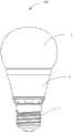
图1是本发明一实施方式的LED球泡灯的立体分解图;Fig. 1 is a three-dimensional exploded view of an LED bulb lamp according to an embodiment of the present invention;
图2是图1所示LED球泡灯组装后的主视图;Fig. 2 is a front view of the assembled LED bulb shown in Fig. 1;
图3是图1所示LED球泡灯的剖面示意图;Fig. 3 is a schematic cross-sectional view of the LED bulb shown in Fig. 1;
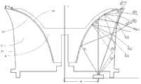
图4是图1所示LED球泡灯中透镜和反射件的光路示意图;Fig. 4 is a schematic diagram of the optical path of the lens and reflector in the LED bulb shown in Fig. 1;
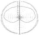
图5是图1所示LED球泡灯的配光曲线图。FIG. 5 is a light distribution curve diagram of the LED bulb shown in FIG. 1 .
主要元件符号说明Description of main component symbols
100、LED球泡灯;1、灯头;2、散热件;3、灯泡壳;4、LED光源;100. LED bulb lamp; 1. Lamp holder; 2. Heat sink; 3. Bulb shell; 4. LED light source;
5、透镜;51、第一曲面;52、凹槽;53、第二曲面;54、第一凸台;5. Lens; 51. First curved surface; 52. Groove; 53. Second curved surface; 54. First boss;
6、反射件;61、反射面;7、凸台;71、卡槽;6. Reflector; 61. Reflective surface; 7. Boss; 71. Card slot;
具体实施方式Detailed ways
为详细说明本发明的技术内容、构造特征、所实现目的及效果,以下结合实施方式并配合附图详予说明。In order to describe the technical content, structural features, achieved goals and effects of the present invention in detail, the following will be described in detail in conjunction with the embodiments and accompanying drawings.
请一并参阅图1至图3,本发明的LED球泡灯100包括基板、散热件2以及灯泡壳3。该基板设置在该散热件2的顶部,该基板的顶部设有多个LED光源4,该灯泡壳3罩设在该散热件2的顶部。在本实施方式中,LED光源4为表面贴装型LED光源。LED球泡灯100还包括设置在LED光源4上方的配光结构,配光结构包括透镜5以及反射件6。该透镜5呈圆柱状,透镜5的底面罩设在LED光源4上方(如图3所示),LED光源4环绕地设置在该透镜5底面的下方,在本实施方式中,LED光源4呈圆环状设置在基板上(如图1所示),且靠近该基板的边缘设置。Please refer to FIG. 1 to FIG. 3 together. The
请参照图1及图3,该散热件2的顶面设有凸台7,该基板设置在该凸台7的顶面。该凸台7外表面涂覆有反射材料,该凸台7用于抬高该基板及该透镜5在该灯泡壳3内的高度,避免从该透镜5中射出的光线被基板遮挡产生死角,扩大发光角度。在本实施方式中,透镜5底面的端缘向外凸设有多个第一卡块54,凸台7顶面的边缘环绕这些LED光源4设有与卡块54数量相等的卡槽71,该第一卡块54与对应的卡槽71扣接,从而将所述透镜5固定在所述凸台7上。Referring to FIG. 1 and FIG. 3 , the top surface of the
请参照图1、图3及图4,该透镜5的外侧面呈第一曲面51。透镜5的远离所述LED光源4的顶面上开设有凹槽52(如图1所示),该凹槽52的内壁呈第二曲面53(如图4所示)。该第二曲面53为旋转曲面结构且对应这些呈圆环状排列的LED光源4设置,该第二曲面53位于这些LED光源4围成的圆环的内侧及上方,以半包围的形式覆盖这些LED光源4。该第一曲面51位于所述LED光源4围成的圆环的外侧,该第一曲面51靠近这些LED光源4的部分为大致与该透镜5的底面垂直的圆柱状侧壁,以将大部分从这些LED光源4发出并经过该透镜5底面折射的光朝向该第二曲面53反射;该第一曲面51远离这些LED光源4的部分为弧状弯折的曲面以与该第二曲面53的端部连接。当然,另有部分光直接从该第一曲面51处向外折射。该第二曲面53用于反射或折射这些LED光源4发出的并经过该透镜5底面折射的向内发出的内侧光线以及部分向外发出的外侧光线。Please refer to FIG. 1 , FIG. 3 and FIG. 4 , the outer surface of the
该凹槽52内安装有反射件6,在本实施方式中,该反射件6组装在该透镜5的凹槽52内。该反射件6呈伞状,该反射件6具有反射面61,该反射面61与该第二曲面53匹配,用于对从该第二曲面53折射出来的光线进行反射,使这些光线再次进入该透镜5内。在本实施方式中,该反射件6的反射面61上涂覆有散射白漆,该散射白漆的功能在于对光线进行混光,防止该透镜5折射分光。The
请参阅图4-5,图4是透镜和反射件的剖面图及光路示意图,以对一颗LED光源4发出的光线进行导光的原理为例,对本发明的透镜及反射件的工作原理进行描述。LED光源4距离透镜5的转轴y的垂直距离m,所述透镜5的第二曲面53用于将大部分从LED光源4发出并经过透镜5底面折射的向内发出的内侧光线S1朝向第一曲面51反射,再经过第一曲面51折射出去形成第一出射光线S11,其中,大部分第一出射光线S11从水平线的下侧射出,照向该散热件2所在的该LED球泡灯100的后侧区域,以达到大角度的要求。Please refer to Fig. 4-5, Fig. 4 is a sectional view of a lens and a reflector and a schematic diagram of an optical path, taking the principle of guiding light emitted by an LED light source 4 as an example, the working principle of the lens and reflector of the present invention is carried out describe. The vertical distance m between the LED light source 4 and the rotation axis y of the
第一曲面53用于对LED光源4发出并经过透镜5底面折射的一部分向外发出的外侧光线S2进行反射,反射的光线通过第二曲面51折射至所述伞状反射件6的反射面61上,该反射面61用于对第二曲面51折射的光线进行漫反射,经过漫反射的光线再通过第二曲面透镜5折射出去形成第二出射光线S22。The first
进一步地,为了使配光曲线均匀,让配光曲线的0°-45°部分也有光线,在本实施方式中,反射件6远离LED光源4的端缘与该透镜5远离LED光源的端缘间隔一定长度n形成透光区,该透光区为环状结构,LED光源4发出的并经过透镜5底面折射的一部分外侧光线S3由该透光区直接折射为第三出射光线S33,第三出射光线S33组成图5中配光曲线的0-45°部分,其中,该透光区经过雾化处理。在其他实施方式中,还可通过在灯泡壳3上设置透光散射材料,实现大角度发光。Further, in order to make the light distribution curve uniform, so that the 0°-45° part of the light distribution curve also has light, in this embodiment, the end edge of the
综上所述,本发明的LED球泡灯通过设置该透镜及该散射板组成的配光结构,将该配光结构设置在这些呈环形排列的LED光源的上方,利用透镜的第二曲面、第一曲面及该反射件对LED光源发出并经过该透镜底面折射的光线进行配光,使得光线可以照向该散热件2所在的该LED球泡灯100的后侧区域,从而可以实现大角度发光。进一步地,为了增强0-45°配光,在反射件远离LED光源的端缘与该透镜第一曲面远离LED光源的端缘间隔一定长度形成环状透光区,该透光区将一部分外侧光线直接折射为组成配光曲线的0-45°部分的出射光。To sum up, the LED bulb lamp of the present invention is provided with the light distribution structure composed of the lens and the scattering plate, and the light distribution structure is arranged above the LED light sources arranged in a ring, and utilizes the second curved surface of the lens, The first curved surface and the reflector distribute the light emitted by the LED light source and refracted by the bottom surface of the lens, so that the light can shine on the rear area of the
因此,本发明的LED球泡灯通过配光结构对环绕地设置在该透镜底面下方的LED光源实现大角度配光,光束角大于270°,且配光曲线均匀性好,整灯的外观与传统球泡灯接近。相对于市面上LED A60加透镜透明球泡灯,本发明的LED球泡灯的光分布角度大,实测的半峰值光束角达到280°,配光曲线均匀,亮度均匀。并且视觉感受光是从透镜发出的,点亮效果好,更加接近于传统A60白炽灯的照明效果。Therefore, the LED bulb lamp of the present invention realizes large-angle light distribution to the LED light source surroundingly arranged under the bottom surface of the lens through the light distribution structure, the beam angle is greater than 270°, and the uniformity of the light distribution curve is good. Traditional bulbs are close. Compared with the LED A60 plus lens transparent bulb lamp on the market, the LED bulb lamp of the present invention has a larger light distribution angle, the measured half-peak beam angle reaches 280°, uniform light distribution curve, and uniform brightness. And the visual experience light is emitted from the lens, and the lighting effect is good, which is closer to the lighting effect of the traditional A60 incandescent lamp.
可以理解的,该反射件6也可以为涂覆在该第二曲面53上的反射漆层,从而进一步简化结构。It can be understood that the
以上所述仅为本发明的实施例,并非因此限制本发明的专利范围,凡是利用本发明说明书及附图内容所作的等效结构或等效流程变换,或直接或间接运用在其他相关的技术领域,均同理包括在本发明的专利保护范围内。The above is only an embodiment of the present invention, and does not limit the patent scope of the present invention. Any equivalent structure or equivalent process transformation made by using the description of the present invention and the contents of the accompanying drawings, or directly or indirectly used in other related technologies fields, all of which are equally included in the scope of patent protection of the present invention.
Claims (10)
Priority Applications (1)
| Application Number | Priority Date | Filing Date | Title |
|---|---|---|---|
| CN201210265420.3ACN102788268B (en) | 2012-07-27 | 2012-07-27 | LED Bulb |
Applications Claiming Priority (1)
| Application Number | Priority Date | Filing Date | Title |
|---|---|---|---|
| CN201210265420.3ACN102788268B (en) | 2012-07-27 | 2012-07-27 | LED Bulb |
Publications (2)
| Publication Number | Publication Date |
|---|---|
| CN102788268Atrue CN102788268A (en) | 2012-11-21 |
| CN102788268B CN102788268B (en) | 2016-04-20 |
Family
ID=47153762
Family Applications (1)
| Application Number | Title | Priority Date | Filing Date |
|---|---|---|---|
| CN201210265420.3AExpired - Fee RelatedCN102788268B (en) | 2012-07-27 | 2012-07-27 | LED Bulb |
Country Status (1)
| Country | Link |
|---|---|
| CN (1) | CN102788268B (en) |
Cited By (8)
| Publication number | Priority date | Publication date | Assignee | Title |
|---|---|---|---|---|
| CN102980075A (en)* | 2012-12-26 | 2013-03-20 | 深圳市洲明科技股份有限公司 | LED (Light-emitting Diode) large-angle light distribution device and LED bulb |
| CN103836412A (en)* | 2012-11-22 | 2014-06-04 | 恩普乐股份有限公司 | Lighting device |
| CN103953867A (en)* | 2014-05-05 | 2014-07-30 | 立达信绿色照明股份有限公司 | Full-ambient-light LED (light-emitting diode) bulb lamp |
| WO2014201598A1 (en)* | 2013-06-17 | 2014-12-24 | 欧普照明股份有限公司 | Led lamp |
| CN106287276A (en)* | 2015-08-28 | 2017-01-04 | 中山市绿涛电子科技有限公司 | light bulb for lighting |
| WO2017067266A1 (en)* | 2015-10-20 | 2017-04-27 | 漳州立达信灯具有限公司 | Bulb casing fixing structure |
| CN108036208A (en)* | 2017-12-31 | 2018-05-15 | 普天智能照明研究院有限公司 | A kind of optics light distribution module and there is its ball bulb lamp structure |
| CN111623267A (en)* | 2020-06-22 | 2020-09-04 | 欧普照明股份有限公司 | Lamp and bulb shell thereof |
Citations (7)
| Publication number | Priority date | Publication date | Assignee | Title |
|---|---|---|---|---|
| US20050263785A1 (en)* | 2004-05-27 | 2005-12-01 | Samsung Electro-Mechanics Co., Ltd. | Light emitting diode device |
| CN101201415A (en)* | 2006-12-15 | 2008-06-18 | 鸿富锦精密工业(深圳)有限公司 | Light-guiding lens and light-emitting diode using the light-guiding lens |
| CN102235594A (en)* | 2010-05-04 | 2011-11-09 | 艾迪光电(杭州)有限公司 | Light-emitting diode (LED) light-emitting module |
| CN102305363A (en)* | 2011-08-30 | 2012-01-04 | 厦门立明光电有限公司 | Large-angle omnidirectional lighting LED (light emitting diode) lamp |
| WO2012029711A1 (en)* | 2010-08-31 | 2012-03-08 | 東芝ライテック株式会社 | Lens, lighting system, bulb-shaped lamp, and lighting fixture |
| CN202274308U (en)* | 2011-09-15 | 2012-06-13 | 浙江世明光学科技有限公司 | Light emitting diode (LED) bulb lamp |
| CN202284732U (en)* | 2011-08-29 | 2012-06-27 | 漳州灿坤实业有限公司 | LED bulb lamp having a light-emitting angle of 270 DEG |
- 2012
- 2012-07-27CNCN201210265420.3Apatent/CN102788268B/ennot_activeExpired - Fee Related
Patent Citations (7)
| Publication number | Priority date | Publication date | Assignee | Title |
|---|---|---|---|---|
| US20050263785A1 (en)* | 2004-05-27 | 2005-12-01 | Samsung Electro-Mechanics Co., Ltd. | Light emitting diode device |
| CN101201415A (en)* | 2006-12-15 | 2008-06-18 | 鸿富锦精密工业(深圳)有限公司 | Light-guiding lens and light-emitting diode using the light-guiding lens |
| CN102235594A (en)* | 2010-05-04 | 2011-11-09 | 艾迪光电(杭州)有限公司 | Light-emitting diode (LED) light-emitting module |
| WO2012029711A1 (en)* | 2010-08-31 | 2012-03-08 | 東芝ライテック株式会社 | Lens, lighting system, bulb-shaped lamp, and lighting fixture |
| CN202284732U (en)* | 2011-08-29 | 2012-06-27 | 漳州灿坤实业有限公司 | LED bulb lamp having a light-emitting angle of 270 DEG |
| CN102305363A (en)* | 2011-08-30 | 2012-01-04 | 厦门立明光电有限公司 | Large-angle omnidirectional lighting LED (light emitting diode) lamp |
| CN202274308U (en)* | 2011-09-15 | 2012-06-13 | 浙江世明光学科技有限公司 | Light emitting diode (LED) bulb lamp |
Cited By (10)
| Publication number | Priority date | Publication date | Assignee | Title |
|---|---|---|---|---|
| CN103836412A (en)* | 2012-11-22 | 2014-06-04 | 恩普乐股份有限公司 | Lighting device |
| CN103836412B (en)* | 2012-11-22 | 2017-03-01 | 恩普乐股份有限公司 | Illuminator |
| CN102980075A (en)* | 2012-12-26 | 2013-03-20 | 深圳市洲明科技股份有限公司 | LED (Light-emitting Diode) large-angle light distribution device and LED bulb |
| WO2014201598A1 (en)* | 2013-06-17 | 2014-12-24 | 欧普照明股份有限公司 | Led lamp |
| CN103953867A (en)* | 2014-05-05 | 2014-07-30 | 立达信绿色照明股份有限公司 | Full-ambient-light LED (light-emitting diode) bulb lamp |
| CN106287276A (en)* | 2015-08-28 | 2017-01-04 | 中山市绿涛电子科技有限公司 | light bulb for lighting |
| CN106322156A (en)* | 2015-08-28 | 2017-01-11 | 中山市绿涛电子科技有限公司 | A LED light bulb with good light efficiency |
| WO2017067266A1 (en)* | 2015-10-20 | 2017-04-27 | 漳州立达信灯具有限公司 | Bulb casing fixing structure |
| CN108036208A (en)* | 2017-12-31 | 2018-05-15 | 普天智能照明研究院有限公司 | A kind of optics light distribution module and there is its ball bulb lamp structure |
| CN111623267A (en)* | 2020-06-22 | 2020-09-04 | 欧普照明股份有限公司 | Lamp and bulb shell thereof |
Also Published As
| Publication number | Publication date |
|---|---|
| CN102788268B (en) | 2016-04-20 |
Similar Documents
| Publication | Publication Date | Title |
|---|---|---|
| CN102788268B (en) | LED Bulb | |
| KR101948378B1 (en) | Omni-directional reflector comprising a frusto-conical surface for a light-emitting diode | |
| US8641238B2 (en) | Light source module | |
| JP6217972B2 (en) | lighting equipment | |
| CN101988646A (en) | Lamp | |
| TW201209322A (en) | Lamp | |
| CN105960560B (en) | Lighting device | |
| CN103378280B (en) | Lenses for LEDs | |
| CN104712938B (en) | Large Angle LED Light | |
| TWM461760U (en) | Optical lens and light source device | |
| CN108278540A (en) | Lighting device | |
| CN104075250A (en) | Light distribution structure and LED lamp thereof | |
| CN103672461B (en) | LED lamp | |
| TWI545376B (en) | Led unit and lens thereof | |
| JP2013045530A (en) | Light emitting device and lighting apparatus | |
| CN104296068A (en) | Lens for lighting device and lighting device with same | |
| JP6917584B2 (en) | Lenses and luminaires | |
| CN104121495A (en) | A full light distribution LED bulb lamp | |
| JP2013531357A (en) | Single chamber lighting device | |
| US20150146432A1 (en) | Light source module | |
| CN104033757B (en) | Large-angle luminous LED lamp | |
| TWI470170B (en) | Illumination apparatus | |
| CN203892941U (en) | Large-angle light-emitting LED lamp | |
| KR101389979B1 (en) | Led lamp | |
| CN104948944B (en) | Wide-angle LED lamp |
Legal Events
| Date | Code | Title | Description |
|---|---|---|---|
| C06 | Publication | ||
| PB01 | Publication | ||
| C10 | Entry into substantive examination | ||
| SE01 | Entry into force of request for substantive examination | ||
| C41 | Transfer of patent application or patent right or utility model | ||
| TA01 | Transfer of patent application right | Effective date of registration:20160105 Address after:Xingtai Industrial Park Economic Development Zone, Changtai County, Fujian city of Zhangzhou Province Applicant after:LEEDARSON LIGHTING Co.,Ltd. Address before:The Lake District of Xiamen City, Fujian province 361010 Fang Hubei two Road No. 1511 Applicant before:Leedarson Lighting (Xiamen) Co.,Ltd. | |
| C14 | Grant of patent or utility model | ||
| GR01 | Patent grant | ||
| CF01 | Termination of patent right due to non-payment of annual fee | ||
| CF01 | Termination of patent right due to non-payment of annual fee | Granted publication date:20160420 |