CN102788141A - Machine oil discharge structure of speed transmission - Google Patents
Machine oil discharge structure of speed transmissionDownload PDFInfo
- Publication number
- CN102788141A CN102788141ACN2012100940338ACN201210094033ACN102788141ACN 102788141 ACN102788141 ACN 102788141ACN 2012100940338 ACN2012100940338 ACN 2012100940338ACN 201210094033 ACN201210094033 ACN 201210094033ACN 102788141 ACN102788141 ACN 102788141A
- Authority
- CN
- China
- Prior art keywords
- chamber
- rotating body
- rib
- rotation
- outer peripheral
- Prior art date
- Legal status (The legal status is an assumption and is not a legal conclusion. Google has not performed a legal analysis and makes no representation as to the accuracy of the status listed.)
- Granted
Links
Images


Landscapes
- General Details Of Gearings (AREA)
Abstract
Translated fromChinese
Description
Translated fromChinese技术领域technical field
本发明涉及变速器的机油排出构造,在变速箱的内部隔着分隔壁而划分出第一室及第二室,在从所述第一室内贯穿所述分隔壁而向所述第二室内伸出的第一旋转轴上设置第一旋转体,将伴随所述第一旋转体的旋转而从其外周部沿切线方向飞散的机油向形成于所述第一室的底部的储油部排出。The present invention relates to an oil discharge structure of a transmission. A first chamber and a second chamber are divided through a partition wall inside the gearbox, and the first chamber penetrates the partition wall and protrudes into the second chamber. A first rotating body is provided on the first rotating shaft of the first rotating body, and engine oil scattered in a tangential direction from an outer peripheral portion of the first rotating body is discharged to an oil storage portion formed at the bottom of the first chamber as the first rotating body rotates.
背景技术Background technique
由下述专利文献1公开了如下结构:由具有回油孔21的分隔壁2将变速器的壳体3的内部分隔成第一室4及第二室5,利用设置于分隔壁2的回油肋20将在第二室5的内部旋转的齿轮17所扬起的机油向回油孔21引导,由此,机油从第二室5回流至第一室4。The following structure is disclosed by the following patent document 1: the interior of the housing 3 of the transmission is divided into a
另外,由下述专利文献2公开了如下结构:由配置在变速器的主箱体670的内部的划分壁部301划分出用于收纳旋转的鼓691的变速齿轮收纳部101、和捕获并储存由鼓691扬起的机油的捕获箱350,将预定量的机油储存在捕获箱350中,由此,适当地维持主箱体670中的机油的液面来降低齿轮等对机油产生的搅拌阻力。In addition, the following
【现有技术文献】[Prior Art Literature]
【专利文献1】日本特开平11-118027号公报[Patent Document 1] Japanese Patent Application Laid-Open No. 11-118027
【专利文献2】日本特开2009-168150号公报[Patent Document 2] Japanese Patent Laid-Open No. 2009-168150
然而,由分隔壁将变速器的壳体划分成第一室及第二室,使积存在第二室中的机油从分隔壁的连通孔向第一室回流的情况下,在第二室的内部存在有:从配置于此的旋转体飞散的机油的流动、和沿第二室的内周壁面因重力流下的机油的流动,因此,若没有以避免这两种机油的流动相互干涉的方式设置连通孔的位置,则存在下述可能性:机油被过度搅拌而产生气泡,或者,机油朝向连通孔的顺畅的流动被阻碍而导致第二室的机油的液面上升且搅拌阻力增加。However, when the case of the transmission is divided into the first chamber and the second chamber by the partition wall, and the oil accumulated in the second chamber flows back to the first chamber through the communication hole of the partition wall, the inside of the second chamber There are: the flow of the engine oil scattered from the rotating body arranged here, and the flow of the engine oil flowing down by gravity along the inner peripheral wall surface of the second chamber, so if there is no way to prevent the two flows of the engine oil from interfering with each other If the position of the communication hole is different, there is a possibility that the oil is excessively stirred to generate air bubbles, or the smooth flow of the oil toward the communication hole is hindered, causing the liquid level of the oil in the second chamber to rise and the stirring resistance to increase.
发明内容Contents of the invention
本发明就是鉴于上述情况而完成的,其目的在于:通过将积存于变速器的壳体的第二室中的机油顺畅地排出到第一室,从而减小因配置在第二室的旋转体产生的机油的搅拌阻力,并且减少气泡向机油中的混入。The present invention has been made in view of the above circumstances, and its object is to reduce the oil generated by the rotating body arranged in the second chamber by smoothly discharging the oil accumulated in the second chamber of the transmission case to the first chamber. The stirring resistance of the engine oil, and reduce the mixing of air bubbles into the oil.
为了实现上述目的,根据技术方案1记载的发明,提出一种变速器的机油排出结构,其中,在壳体的内部隔着分隔壁而划分出第一室和第二室,在从所述第一室内贯穿所述分隔壁而向所述第二室内伸出的第一旋转轴上设置有第一旋转体,将伴随所述第一旋转体的旋转而从其外周部沿切线方向飞散的机油向形成于所述第一室的底部的储油部排出,所述变速器的机油排出结构的特征在于,在所述第二室的与所述第一旋转体的下部外周面对置的第一壁面形成有朝向该第一旋转体的外周面突出的第一肋,在面对所述第一肋的靠所述第一旋转体的旋转方向滞后侧的所述分隔壁,形成有使所述第二室与所述第一室连通的第一连通孔,并且,在面对所述第一肋的靠所述第一旋转体的旋转方向提前侧的所述分隔壁,形成有使所述第二室与所述第一室连通的第二连通孔。In order to achieve the above object, according to the invention described in claim 1, an engine oil discharge structure for a transmission is proposed, wherein a first chamber and a second chamber are divided into a first chamber and a second chamber through a partition wall inside the casing, A first rotating body is provided on a first rotating shaft in the chamber penetrating through the partition wall and protruding into the second chamber, and the engine oil scattered from the outer peripheral portion of the first rotating body in a tangential direction along with the rotation of the first rotating body is provided to the second chamber. The oil reservoir formed at the bottom of the first chamber is discharged. The oil discharge structure of the transmission is characterized in that the first wall surface of the second chamber facing the lower outer peripheral surface of the first rotating body A first rib protruding toward the outer peripheral surface of the first rotating body is formed, and the partition wall on the lagging side of the rotation direction of the first rotating body facing the first rib is formed so that the first rotating body The first communication hole through which the second chamber communicates with the first chamber, and the partition wall facing the first rib on the side where the rotation direction of the first rotating body advances is formed so that the second chamber is connected to the first chamber. A second communicating hole through which the second chamber communicates with the first chamber.
另外,根据技术方案2记载的发明,在技术方案1的结构的基础上,提出一种变速器的机油排出结构,其特征在于,在从所述第一室内贯穿所述分隔壁而向所述第二室内伸出的第二旋转轴上设置有第二旋转体,第二壁面从与所述第二旋转体的上部外周面对置的位置朝向该第二旋转体的旋转方向提前侧向斜下方延伸,从该第二壁面的端部突出设置有朝向所述第二旋转体的外周面延伸的第二肋,在面对被夹在所述第二壁面与所述第二肋之间的位置的所述分隔壁,形成有使所述第二室与所述第一室连通的第三连通孔。In addition, according to the invention described in
另外,根据技术方案3记载的发明,在技术方案1的结构的基础上,提出一种变速器的机油排出结构,其特征在于,在从所述第一室内贯穿所述分隔壁而向所述第二室内伸出的第二旋转轴上设置有第二旋转体,第三壁面从与所述第二旋转体的上部外周面对置的位置朝向该第二旋转体的旋转方向滞后侧向下方延伸,从该第三壁面的端部突出设置有朝向所述第二旋转体的外周面延伸的第三肋,在面对被夹在所述第三壁面与所述第三肋之间的位置的所述分隔壁,形成有使所述第二室与所述第一室连通的第四连通孔。In addition, according to the invention described in claim 3, in addition to the structure of claim 1, there is proposed an engine oil discharge structure for a transmission, characterized in that the first chamber penetrates the partition wall to the second A second rotating body is provided on the second rotating shaft protruding from the second chamber, and the third wall surface extends downward from a position facing the upper outer peripheral surface of the second rotating body toward the lagging side of the rotation direction of the second rotating body , protruding from the end of the third wall is a third rib extending toward the outer peripheral surface of the second rotating body, facing the position sandwiched between the third wall and the third rib The partition wall is formed with a fourth communication hole that communicates the second chamber with the first chamber.
另外,根据技术方案4记载的发明,在技术方案2或技术方案3的结构的基础上,提出一种变速器的机油排出结构,其特征在于,所述第一旋转轴和所述第二旋转轴的旋转方向相同,在轴向观察所述第一、第二旋转轴的旋转方向为逆时针方向的情况下,所述第二旋转轴位于所述第一旋转轴的右侧上方,在轴向观察所述第一、第二旋转轴的旋转方向为顺时针方向的情况下,所述第二旋转轴位于所述第一旋转轴的左侧上方。In addition, according to the invention described in
另外,根据技术方案5记载的发明,在技术方案2或技术方案3的结构的基础上,提出一种变速器的机油排出结构,其特征在于,所述第二室的形状是包围所述第一旋转体和所述第二旋转体的周围的长圆形状或椭圆形状。In addition, according to the invention described in
另外,根据技术方案6记载的发明,在技术方案4的结构的基础上,提出一种变速器的机油排出结构,其特征在于,所述第二室的形状是包围所述第一旋转体和所述第二旋转体的周围的长圆形状或椭圆形状。In addition, according to the invention described in claim 6, in addition to the structure of
此外,实施方式的第一主输入轴13与本发明的第一旋转轴对应,实施方式的第二主输入轴14与本发明的第二旋转轴对应,实施方式的第一离合器17与本发明的第一旋转体对应,实施方式的第二离合器18与本发明的第二旋转体对应,实施方式的变速器箱体52及箱体罩53与本发明的壳体对应,实施方式的油底壳56与本发明的储油部对应。In addition, the first
发明效果Invention effect
根据技术方案1的结构,在第二室的与设置在第一旋转轴上的第一旋转体的下部外周面对置的第一壁面,形成有朝向该第一旋转体的外周面突出的第一肋,在面对第一肋的靠第一旋转体的旋转方向滞后侧的分隔壁,形成有使第二室与第一室连通的第一连通孔,并且,在面对第一肋的靠第一旋转体的旋转方向提前侧的分隔壁形成有使第二室与第一室连通的第二连通孔,所以,从第一旋转体的外周面向旋转方向提前侧飞散的机油和朝向第二室的第一壁面从旋转方向滞后侧流下的机油被第一肋遮挡而不发生正面碰撞,能够防止因机油的搅拌导致气泡的产生,并能够使在第一肋的两侧捕获的机油分别通过第一连通孔和第二连通孔而向第一室顺畅地排出。由此,能够使配置在第二室的第一旋转体不浸渍于机油中而降低搅拌阻力。According to the structure of claim 1, the first wall surface of the second chamber facing the lower outer peripheral surface of the first rotating body provided on the first rotating shaft is formed with a second wall protruding toward the outer peripheral surface of the first rotating body. A rib is formed with a first communication hole for communicating the second chamber with the first chamber on the partition wall facing the first rib and on the lagging side of the rotation direction of the first rotating body, and, on the partition wall facing the first rib, The partition wall on the advancing side of the rotation direction of the first rotating body is formed with a second communication hole that communicates the second chamber with the first chamber, so the oil scattered from the outer peripheral surface of the first rotating body toward the advancing side of the rotating direction and the The oil flowing down the first wall of the second chamber from the lagging side of the rotation direction is blocked by the first rib without frontal collision, which can prevent the generation of air bubbles caused by the stirring of the oil, and can separate the oil captured on both sides of the first rib. It is smoothly discharged into the first chamber through the first communication hole and the second communication hole. Thereby, the stirring resistance can be reduced without immersing the first rotating body arranged in the second chamber in the engine oil.
另外,根据技术方案2的结构,在从第一室内贯穿分隔壁而向第二室内伸出的第二旋转轴上设置有第二旋转体,第二壁面从与第二旋转体的上部外周面对置的位置朝向该第二旋转体的旋转方向提前侧向斜下方延伸,从该第二壁面的端部突出设置有朝向第二旋转体的外周面延伸的第二肋,在面对被夹在第二壁面与第二肋之间的位置的分隔壁,形成有使第二室与第一室连通的第三连通孔,所以,从第二旋转体飞散的机油和从第一旋转体飞散的机油被第二肋遮挡,能够防止它们碰撞以防止气泡的产生,并能够将被第二肋捕获的机油通过第三连通孔而向第一室顺畅地排出。In addition, according to the structure of
另外,根据技术方案3的结构,在从第一室内贯穿分隔壁而向第二室内伸出的第二旋转轴上设置有第二旋转体,第三壁面从与第二旋转体的上部外周面对置的位置朝向该第二旋转体的旋转方向滞后侧向下方延伸,从该第三壁面的端部突出设置有朝向第二旋转体的外周面延伸的第三肋,在面对被夹在第三壁面与第三肋之间的位置的分隔壁,形成有使第二室与第一室连通的第四连通孔,所以,附着于第三壁面而因重力流下的机油和从第二旋转体飞散的机油被第三肋遮挡,能够避免它们碰撞以防止气泡的产生,并能够将被第三肋捕获的机油通过第四连通孔而向第一室顺畅地排出。In addition, according to the structure of claim 3, the second rotating body is provided on the second rotating shaft extending from the first chamber through the partition wall to the second chamber, and the third wall surface is connected to the upper outer peripheral surface of the second rotating body. The opposite position extends downward toward the lagging side of the rotation direction of the second rotating body, and a third rib extending toward the outer peripheral surface of the second rotating body protrudes from the end of the third wall surface, and is sandwiched between the facing parts. The partition wall at the position between the third wall surface and the third rib is formed with a fourth communication hole that communicates the second chamber with the first chamber, so the oil that adheres to the third wall surface and flows down due to gravity is separated from the second rotating chamber. The engine oil scattered by the body is blocked by the third rib, which can avoid their collision to prevent the generation of air bubbles, and the engine oil captured by the third rib can be smoothly discharged to the first chamber through the fourth communication hole.
另外,根据技术方案4的结构,第一旋转轴和第二旋转轴的旋转方向相同,在轴向观察第一、第二旋转轴的旋转方向为逆时针方向的情况下,第二旋转轴位于第一旋转轴的右侧上方,在轴向观察第一、第二旋转轴的旋转方向为顺时针方向的情况下,第二旋转轴位于第一旋转轴的左侧上方,所以,附着于第二室的内周壁面的顶壁部分的机油因重力流下的方向、和从第一、第二旋转体沿切线方向飞散的机油的移动方向相同,能够使附着于第二室的内周壁面的顶壁部分的机油顺畅地流动并排出。In addition, according to the structure of
另外,根据技术方案5和技术方案6的结构,第二室的形状是包围第一旋转体和第二旋转体的周围的长圆形状或椭圆形状,所以,从第一、第二旋转体的外周面飞散的机油直接被第二室的内周壁面拦截,能够将气泡的产生抑制到最小限度。In addition, according to the structure of
附图说明Description of drawings
图1是双离合式变速器的框架图。Figure 1 is a block diagram of a dual-clutch transmission.
图2是从与发动机相反的一侧观察变速器的图(沿图5及图6的2-2线的向视图)。Fig. 2 is a view of the transmission viewed from the side opposite to the engine (view along line 2-2 in Figs. 5 and 6).
图3是从图2中拆除了第一、第二离合器的图。Fig. 3 is a view with the first and second clutches removed from Fig. 2 .
图4是沿图5及图6的4-4线的向视图。Fig. 4 is a view taken along line 4-4 in Fig. 5 and Fig. 6 .
图5是沿图2及图3的5-5线的剖视图。Fig. 5 is a cross-sectional view along line 5-5 in Fig. 2 and Fig. 3 .
图6是沿图2及图3的6-6线的剖视图。Fig. 6 is a cross-sectional view along line 6-6 in Figs. 2 and 3 .
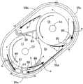
图7是与图2对应的示意图。FIG. 7 is a schematic diagram corresponding to FIG. 2 .
标号说明Label description
13 第一主输入轴(第一旋转轴)13 The first main input shaft (the first rotary shaft)
14 第二主输入轴(第二旋转轴)14 Second main input shaft (second rotary shaft)
17 第一离合器(第一旋转体)17 first clutch (first rotating body)
18 第二离合器(第二旋转体)18 Second clutch (second rotating body)
52 变速器箱体(壳体)52 Transmission case (housing)
52a 分隔壁52a Partition wall
53 箱体罩(壳体)53 box cover (shell)
54 第一室54 Room 1
55 第二室55 Second Room
55a 第一壁面55a First wall
55b 第二壁面55b Second wall
55c 第三壁面55c third wall
56 油底壳(储油部)56 Oil pan (oil storage part)
57 第一连通孔57 The first connecting hole
58 第二连通孔58 The second connecting hole
59 第三连通孔59 The third connecting hole
60 第四连通孔60 The fourth connecting hole
61 第一肋61 First rib
64 第二肋64 second rib
65 第三肋65 third rib
具体实施方式Detailed ways
以下,基于图1~图7说明本发明的实施方式。Hereinafter, an embodiment of the present invention will be described based on FIGS. 1 to 7 .
如图1所示,汽车用的双离合式的变速器T具有:第一主输入轴13,其经由液力变矩器12与发动机E的曲轴11同轴地连接;和相对于第一主输入轴13平行地配置的第二主输入轴14。在第一主输入轴13和第二主输入轴14的外周分别以能够相对自由旋转的方式嵌合有筒状的第一副输入轴15和第二副输入轴16,第一主输入轴13和第一副输入轴15能够经由第一离合器17接合起来,并且,第二主输入轴14和第二副输入轴16能够经由第二离合器18接合起来。As shown in FIG. 1 , the dual-clutch transmission T for automobiles has: a first
与第一主输入轴13及第二主输入轴14平行地配置有输出轴19及惰轴20,固定设置于第一主输入轴13的驱动齿轮21与固定设置于惰轴20的惰轮22啮合,惰轮22与固定设置于第二主输入轴14的从动齿轮23啮合。因此,在发动机E运转时,第一主输入轴13和第二主输入轴14始终同向旋转。An
在第一副输入轴15以能够相对自由旋转的方式支承有1速驱动齿轮24、3速驱动齿轮25、5速驱动齿轮26及7速驱动齿轮27,1速驱动齿轮24及3速驱动齿轮25能够经由1速-3速同步装置28有选择地与第一副输入轴15接合,5速驱动齿轮26及7速驱动齿轮27能够经由5速-7速同步装置29有选择地与第一副输入轴15接合。The 1st
在第二副输入轴16以能够相对自由旋转的方式支承有2速驱动齿轮30、4速驱动齿轮31、6速驱动齿轮32及8速驱动齿轮33,2速驱动齿轮30及4速驱动齿轮31能够经由2速-4速同步装置34有选择地与第二副输入轴16接合,6速驱动齿轮32及8速驱动齿轮33能够经由6速-8速同步装置35有选择地与第二副输入轴16接合。The 2nd
在输出轴19固定设置有1速-2速从动齿轮36、3速-4速从动齿轮37、5速-6速从动齿轮38及7速-8速从动齿轮39,1速-2速从动齿轮36同时与1速驱动齿轮24及2速驱动齿轮30啮合,3速-4速从动齿轮37同时与3速驱动齿轮25及4速驱动齿轮31啮合,5速-6速从动齿轮38同时与5速驱动齿轮26及6速驱动齿轮32啮合,7速-8速从动齿轮39同时与7速驱动齿轮27及8速驱动齿轮33啮合。
在惰轴20上以能够相对自由旋转的方式支承有与第一副输入轴15的1速驱动齿轮24啮合的倒档惰轮40,该倒档惰轮40能够经由倒档离合器41与惰轴20接合。A
固定设置于输出轴19的终减速驱动齿轮(final drive gear)42与固定设置于差动器43的终减速从动齿轮(final driven gear)44啮合,从差动器43向左右延伸的车轴45、45与左右的驱动轮W、W连接。A
因此,在利用1速-3速同步装置28将1速驱动齿轮24与第一副输入轴15接合的状态下卡合第一离合器17时,第一主输入轴13的旋转以第一离合器17→第一副输入轴15→1速-3速同步装置28→1速驱动齿轮24→1速-2速从动齿轮36→输出轴19→终减速驱动齿轮42→终减速从动齿轮44的路径被传递到差动器43,从而确立1速变速档。Therefore, when the first clutch 17 is engaged in the state where the first-
另外,在利用2速-4速同步装置34将2速驱动齿轮30与第二副输入轴16接合的状态下卡合第二离合器18时,第二主输入轴14的旋转以第二离合器18→第二副输入轴16→2速-4速同步装置34→2速驱动齿轮30→1速-2速从动齿轮36→输出轴19→终减速驱动齿轮42→终减速从动齿轮44的路径被传递到差动器43,从而确立2速变速档。In addition, when the second clutch 18 is engaged in the state where the second-
另外,在利用1速-3速同步装置28将3速驱动齿轮25与第一副输入轴15接合的状态下卡合第一离合器17时,第一主输入轴13的旋转以第一离合器17→第一副输入轴15→1速-3速同步装置28→3速驱动齿轮25→3速-4速从动齿轮37→输出轴19→终减速驱动齿轮42→终减速从动齿轮44的路径被传递到差动器43,从而确立3速变速档。In addition, when the first clutch 17 is engaged in the state where the third-
另外,在利用2速-4速同步装置34将4速驱动齿轮31与第二副输入轴16接合的状态下卡合第二离合器18时,第二主输入轴14的旋转以第二离合器18→第二副输入轴16→2速-4速同步装置34→4速驱动齿轮31→3速-4速从动齿轮37→输出轴19→终减速驱动齿轮42→终减速从动齿轮44的路径被传递到差动器43,从而确立4速变速档。In addition, when the second clutch 18 is engaged in the state where the fourth-
另外,在利用5速-7速同步装置29将5速驱动齿轮26与第一副输入轴15接合的状态下卡合第一离合器17时,第一主输入轴13的旋转以第一离合器17→第一副输入轴15→5速-7速同步装置29→5速驱动齿轮26→5速-6速从动齿轮38→输出轴19→终减速驱动齿轮42→终减速从动齿轮44的路径被传递到差动器43,从而确立5速变速档。In addition, when the first clutch 17 is engaged in the state where the fifth-
另外,在利用6速-8速同步装置35将6速驱动齿轮32与第二副输入轴16接合的状态下卡合第二离合器18时,第二主输入轴14的旋转以第二离合器18→第二副输入轴16→6速-8速同步装置35→6速驱动齿轮32→5速-6速从动齿轮38→输出轴19→终减速驱动齿轮42→终减速从动齿轮44的路径被传递到差动器43,从而确立6速变速档。In addition, when the second clutch 18 is engaged in the state where the sixth-
另外,在利用5速-7速同步装置29将7速驱动齿轮27与第一副输入轴15接合的状态下卡合第一离合器17时,第一主输入轴13的旋转以第一离合器17→第一副输入轴15→5速-7速同步装置29→7速驱动齿轮27→7速-8速从动齿轮39→输出轴19→终减速驱动齿轮42→终减速从动齿轮44的路径被传递到差动器43,从而确立7速变速档。In addition, when the first clutch 17 is engaged with the 7th-
另外,在利用6速-8速同步装置35将8速驱动齿轮33与第二副输入轴16接合的状态下卡合第二离合器18时,第二主输入轴14的旋转以第二离合器18→第二副输入轴16→6速-8速同步装置35→8速驱动齿轮33→7速-8速从动齿轮39→输出轴19→终减速驱动齿轮42→终减速从动齿轮44的路径被传递到差动器43,从而确立8速变速档。In addition, when the second clutch 18 is engaged in the state where the 8th-
另外,在卡合倒档离合器41时,第一主输入轴13的旋转以驱动齿轮21→惰轮22→惰轴20→倒档离合器41→倒档惰轮40→1速驱动齿轮24→1速-2速从动齿轮36→输出轴19→终减速驱动齿轮42→终减速从动齿轮44的路径反转地被传递到差动器43,从而确立倒档变速档。In addition, when the reverse clutch 41 is engaged, the rotation of the first
以下,基于图2~图7说明变速器T的壳体的结构。Hereinafter, the configuration of the case of the transmission T will be described based on FIGS. 2 to 7 .
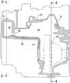
变速器T的壳体由以下部件构成:与发动机体接合的液力变矩器箱体51;与液力变矩器箱体51接合的变速器箱体52;以及与变速箱体52结合的箱体罩53。在液力变矩器箱体51的内部收纳有所述液力变矩器12(参照图5),在形成于变速器箱体52的内部的第一室54中收纳有所述各变速轴及所述各变速齿轮,并以横跨液力变矩器箱体51的内部和变速器箱体52的内部的方式收纳有所述差动器43(参照图6),在以横跨变速器箱体52的内部和箱体罩53的内部的方式形成的第二室55中收纳有所述第一离合器17(参照图5)及第二离合器18。在形成于变速器箱体52的内部的第一室54的底部,形成有储存机油的油底壳56(参照图5)。第一室54及第二室55被变速器箱体52的分隔壁52a(参照图5)分隔开。The casing of the transmission T is composed of the following parts: a
图2是从与发动机E相反的一侧沿轴向观察拆下了箱体罩53的变速器T的图,在变速器箱体52的分隔壁52a形成有用于安装箱体罩53的长圆形(田径赛道形状)的分割面52b,在该分割面52b的内侧划分出第二室55。贯穿变速器箱体52的分隔壁52a的第一主输入轴13、第二主输入轴14及输出轴19的轴端向第二室55内伸出,在第一主输入轴13上设置有第一离合器17,在第二主输入轴14上设置有第二离合器18。2 is a view of the transmission T from which the case cover 53 has been removed, viewed from the side opposite to the engine E in the axial direction, and an oblong ( The
在图2中,第二离合器18相对于第一离合器17被配置在右上方,以隔着少许间隙而包围这些第一离合器17及第二离合器18的外周的方式形成第二室55。在图2中,第一离合器17及第二离合器18的旋转方向都是逆时针方向,另外,输出轴19的位置是第一主输入轴13的右侧且是第二主输入轴14的下侧,惰轴20的位置是第一主输入轴13的上侧且是第二主输入轴14的左侧。差动器43的位置是从第二室55向右下侧远离的位置。In FIG. 2 , the second clutch 18 is arranged on the upper right with respect to the first clutch 17 , and the
图3示出了从图2拆下了第一主输入轴13、第一离合器17、第二主输入轴14、第二离合器18及输出轴19的状态。在变速器箱体52的面对第二室55内部的分隔壁52a,形成有用于使第二室55内的机油回流至第一室54的底部的机油盘56的第一~第四连通孔57、58、59、60。FIG. 3 shows a state where the first
如图2、图3及作为示意图的图7所示,第一肋61从第二室55的与第一离合器17的下部外周面对置的第一壁面55a(参照图7)朝向第一离合器17的下部外周面向上突出,在第一肋61的靠第一离合器17的旋转方向滞后侧形成有第一连通孔57,在第一肋61的靠第二离合器18的旋转方向提前侧形成有第二连通孔58。从第一连通孔57及第二连通孔58向变速器箱体52的内部的第一室54开口的位置起,变速器箱体52的底壁部52c向下倾斜地相连,从该位置伸出肋63,该肋63水平地延伸至被收纳在油底壳56内的过滤器62的上表面中央部(参照图5及图6)。As shown in FIGS. 2 and 3 and FIG. 7 which is a schematic diagram, the
第二壁面55b(参照图7)从与第二离合器18的上部外周面对置的位置朝向该第二离合器18的旋转方向提前侧向斜下方延伸,第二肋64从该第二壁面55b的下端部朝向第二离合器18的侧部外周面突出。而且,在与被夹在第二壁面55b和第二肋64之间的位置面对的分隔壁52a,形成有使第二室55与第一室54连通的第三连通孔59。在变速器箱体52的内部,第三连通孔59直接朝第一室54的上部开口(参照图5)。The
第三壁面55c(参照图7)从与第二离合器18的上部外周面对置的位置朝向该第二离合器18的旋转方向滞后侧向下方延伸,第三肋65从该第三壁面55c的下端部朝向第二离合器18的侧部外周面突出。而且,在与被夹在第三壁面55c和第三肋65之间的位置面对的分隔壁52a,形成有使第二室55与第一室54连通的第四连通孔60。从第四连通孔60朝变速器箱体52的内部的第一室54开口的位置朝向差动器43而形成截面呈V字形的回油通路66和槽状的回油通路67,所述回油通路66沿变速器箱体52的内壁面向下倾斜地延伸,所述回油通路67从该回油通路66的下游端朝下延伸(参照图4及图6)。The
在第一离合器17的相对于第一连通孔57的旋转方向滞后侧,配置有沿着第一离合器17的外周面向旋转方向提前侧延伸的第四肋68。另外,在第一离合器17的相对于第二连通孔58的旋转方向提前侧,配置有沿着第一离合器17的外周面延伸的第五肋69。On the retarding side of the first clutch 17 in the rotational direction relative to the
接下来,对具有上述结构的本发明的实施方式的作用进行说明。Next, the action of the embodiment of the present invention having the above configuration will be described.
如图7所示,第一离合器17和第二离合器18都沿逆时针方向旋转,附着于它们的外周面的机油如虚线箭头所示地朝向旋转方向提前侧沿切线方向飞散。另外,附着于第二室55的内周面的机油因重力向下方流下,并且,在第一离合器17和第二离合器18的旋转停止时,附着于第一离合器17和第二离合器18的外周面的机油因重力滴下。As shown in FIG. 7 , both the first clutch 17 and the second clutch 18 rotate counterclockwise, and the oil adhering to their outer peripheral surfaces is scattered tangentially toward the advancing side of the rotation direction as indicated by the dotted arrows. In addition, the oil adhering to the inner peripheral surface of the
从第一、第二离合器17、18的外周面沿切线方向飞散的机油附着于第二室55的内周壁面的整个区域,但由于附着于第二室55的上侧(顶板侧)的壁面的机油的一部分向下侧(底板侧)的壁面滴下,所以汇集于下侧的壁面的机油沿着该下侧的壁面向箭头a方向流下。另一方面,从第一离合器17的外周面沿切线方向飞散的机油沿着第二室55的与第一离合器17的外周面对置的内周壁面向箭头b方向移动。The engine oil scattered in the tangential direction from the outer peripheral surfaces of the first and
当这些向相反方向流动的机油在第二室55的第一壁面55a上碰撞时,不仅存在机油中产生气泡的问题,还存在机油无法从第一、第二连通孔57、58向第一室54的油底壳56顺畅地排出的问题,但由于在第一、第二连通孔57、58之间设置有第一肋61,所以,沿箭头b方向流动的机油从第一肋61的近前侧的第一连通孔57向第一室54排出,沿箭头a方向流动的机油从第一肋61的近前侧的第二连通孔58向第一室54排出,因此,机油从第二室55向第一室54的排出得以顺畅地进行。When the oil flowing in the opposite direction collides with the
另外,从第一离合器17的外周面沿箭头b方向飞散的机油强烈地与第二室55的内周壁面碰撞时,容易产生气泡,但通过在该位置沿第一离合器17的外周面设置第四肋68,使所述向下飞散的机油在因重力加速之前与第四肋68碰撞,由此能够抑制气泡的产生。另外,从第一离合器17的外周面沿箭头c方向飞散的机油与沿着第二室55的下侧的壁面向箭头a方向流下的机油正面碰撞时,存在产生气泡或机油的流动迟滞的问题,但借助第五肋69分隔开箭头a方向的机油的流动和箭头c方向的机油的流动,能够解决上述问题。In addition, when the oil scattered in the direction of the arrow b from the outer peripheral surface of the first clutch 17 strongly collides with the inner peripheral wall surface of the
进而,从第二室55侧向第一室54侧穿过第一、第二连通孔57、58的机油在变速器箱体52的底壁部52c及肋63的上表面流动而下落到过滤器62的上表面,由此处回流至油底壳56(参照图5)。Furthermore, the oil passing through the first and second communication holes 57 and 58 from the
从第二离合器18的外周部沿着第二室55的第二壁面55b向箭头d方向飞散的机油与从第一离合器17的外周面飞散的机油碰撞时,可能会产生气泡,但通过借助第二肋64将向箭头d方向飞散的机油捕获,由此,能够防止与从第一离合器17的外周面飞散的机油碰撞以抑制气泡的产生,并且能够将被第二肋64捕获的机油从第三连通孔59向第一室54排出。When the engine oil scattered in the direction of arrow d along the
第三肋65的功能与第一肋61的功能类似,利用第三肋65进行遮挡,以免沿着第二室55的第三壁面55c因重力向箭头e方向流下的机油与从第二离合器18的外周面向箭头f方向飞散的机油发生正面碰撞,由此能够防止因碰撞产生气泡,并且,沿箭头e方向流动的机油被第三肋65捕获而向第四连通孔60引导,能够向第一室54顺畅地排出。The function of the
从第二室55穿过第四连通孔60而流入到第一室54的机油在设置于变速器箱体52的内壁面的回油通路66、67中流动而被向差动器43供给,并且在润滑差动器43之后回流至油底壳56(参照图6)。The oil that has flowed from the
如上所述,根据本实施方式,能够将第二室55的机油向第一室54顺畅地排出,能够避免配置在第二室55中的第一离合器17及第二离合器18浸渍于机油中,从而减小机油的搅拌阻力。另外,由于第二室55的形状是包围第一离合器17及第二离合器18的周围的长圆形,所以从第一、第二离合器17、18的外周面飞散的机油直接被第二室55的内周壁面拦截,能够将气泡的产生抑制到最小限度。As described above, according to the present embodiment, the engine oil in the
另外,第一主输入轴13及第二主输入轴14的旋转方向在图2及图7中都是逆时针方向,第二主输入轴14位于第一主输入轴13的右侧上方,所以,附着于第二室55的内周壁面的顶壁部分的机油因重力流下的方向、和机油从第一、第二离合器17、18的外周面飞散的方向(图7的箭头b方向或箭头d方向)相同,因此,能够使附着于所述顶壁部分的机油顺畅地流动而从第一连通孔57或第三连通孔59排出。In addition, the rotation directions of the first
以上,说明了本发明的实施方式,但本发明在不脱离其主旨的范围内能够进行各种设计变更。As mentioned above, although embodiment of this invention was described, various design changes are possible in this invention in the range which does not deviate from the summary.
例如,实施方式的第二室55是具有两个圆弧部和两个直线部的长圆形状,但第二室55也可以是椭圆形状。For example, the
另外,在图2及图7所示的实施方式中,第一主输入轴13及第二主输入轴14都沿逆时针方向旋转,因此,将第二主输入轴14配置在第一主输入轴13的右侧上方,但在第一主输入轴13及第二主输入轴14都沿顺时针方向旋转的情况下,需要将第二主输入轴14配置在第一主输入轴13的左侧上方。In addition, in the embodiment shown in Fig. 2 and Fig. 7, both the first
另外,本发明的第一、第二旋转体不限于实施方式的离合器17、18,也可以是齿轮等旋转体。In addition, the first and second rotating bodies of the present invention are not limited to the
Claims (6)
Translated fromChineseApplications Claiming Priority (2)
| Application Number | Priority Date | Filing Date | Title |
|---|---|---|---|
| JP2011110423AJP5722117B2 (en) | 2011-05-17 | 2011-05-17 | Transmission oil drain structure |
| JP2011-110423 | 2011-05-17 |
Publications (2)
| Publication Number | Publication Date |
|---|---|
| CN102788141Atrue CN102788141A (en) | 2012-11-21 |
| CN102788141B CN102788141B (en) | 2015-05-27 |
Family
ID=47153650
Family Applications (1)
| Application Number | Title | Priority Date | Filing Date |
|---|---|---|---|
| CN201210094033.8AExpired - Fee RelatedCN102788141B (en) | 2011-05-17 | 2012-03-31 | Machine oil discharge structure of speed transmission |
Country Status (2)
| Country | Link |
|---|---|
| JP (1) | JP5722117B2 (en) |
| CN (1) | CN102788141B (en) |
Cited By (7)
| Publication number | Priority date | Publication date | Assignee | Title |
|---|---|---|---|---|
| CN105202162A (en)* | 2014-06-19 | 2015-12-30 | 三菱自动车工业株式会社 | Lubricating structure of transmission |
| CN106870638A (en)* | 2015-11-11 | 2017-06-20 | 住友重机械工业株式会社 | Geared system |
| CN107339410A (en)* | 2016-04-29 | 2017-11-10 | Zf 腓德烈斯哈芬股份公司 | Exclusion body in transmission for vehicles |
| CN105889475B (en)* | 2015-02-12 | 2018-07-27 | 铃木株式会社 | Transmission for vehicle |
| CN109983256A (en)* | 2016-11-25 | 2019-07-05 | 本田技研工业株式会社 | Transmission device |
| CN112469927A (en)* | 2018-07-27 | 2021-03-09 | 加特可株式会社 | Oil filter |
| CN116583686A (en)* | 2020-12-15 | 2023-08-11 | 加特可株式会社 | Device and method for controlling the same |
Families Citing this family (3)
| Publication number | Priority date | Publication date | Assignee | Title |
|---|---|---|---|---|
| JP6260594B2 (en)* | 2015-09-02 | 2018-01-17 | トヨタ自動車株式会社 | Lubricator for power transmission mechanism |
| KR101867680B1 (en)* | 2016-07-29 | 2018-06-14 | 현대위아 주식회사 | Transmission of auto mobile |
| JP6879727B2 (en)* | 2016-12-10 | 2021-06-02 | ジヤトコ株式会社 | Lubricating oil discharge structure |
Citations (3)
| Publication number | Priority date | Publication date | Assignee | Title |
|---|---|---|---|---|
| US4359909A (en)* | 1980-04-03 | 1982-11-23 | Toyota Jidosha Kogyo Kabushiki Kaisha | Transmission |
| JPS60128058U (en)* | 1984-02-06 | 1985-08-28 | トヨタ自動車株式会社 | Transmission lubrication system |
| JPH11118027A (en)* | 1997-10-15 | 1999-04-30 | Aisin Ai Co Ltd | Casing structure of manual transmission |
Family Cites Families (3)
| Publication number | Priority date | Publication date | Assignee | Title |
|---|---|---|---|---|
| JP2748479B2 (en)* | 1988-12-29 | 1998-05-06 | スズキ株式会社 | Continuously variable transmission for vehicles |
| JP2585898Y2 (en)* | 1992-08-26 | 1998-11-25 | ダイハツ工業株式会社 | Lubrication structure of automotive transfer |
| JPH10184861A (en)* | 1996-12-26 | 1998-07-14 | Aisin Aw Co Ltd | Transmission for four-wheel drive vehicle |
- 2011
- 2011-05-17JPJP2011110423Apatent/JP5722117B2/ennot_activeExpired - Fee Related
- 2012
- 2012-03-31CNCN201210094033.8Apatent/CN102788141B/ennot_activeExpired - Fee Related
Patent Citations (3)
| Publication number | Priority date | Publication date | Assignee | Title |
|---|---|---|---|---|
| US4359909A (en)* | 1980-04-03 | 1982-11-23 | Toyota Jidosha Kogyo Kabushiki Kaisha | Transmission |
| JPS60128058U (en)* | 1984-02-06 | 1985-08-28 | トヨタ自動車株式会社 | Transmission lubrication system |
| JPH11118027A (en)* | 1997-10-15 | 1999-04-30 | Aisin Ai Co Ltd | Casing structure of manual transmission |
Cited By (10)
| Publication number | Priority date | Publication date | Assignee | Title |
|---|---|---|---|---|
| CN105202162A (en)* | 2014-06-19 | 2015-12-30 | 三菱自动车工业株式会社 | Lubricating structure of transmission |
| CN105202162B (en)* | 2014-06-19 | 2018-11-06 | 三菱自动车工业株式会社 | The lubricating structure of speed changer |
| CN105889475B (en)* | 2015-02-12 | 2018-07-27 | 铃木株式会社 | Transmission for vehicle |
| CN106870638A (en)* | 2015-11-11 | 2017-06-20 | 住友重机械工业株式会社 | Geared system |
| CN106870638B (en)* | 2015-11-11 | 2020-10-02 | 住友重机械工业株式会社 | Gear device |
| CN107339410A (en)* | 2016-04-29 | 2017-11-10 | Zf 腓德烈斯哈芬股份公司 | Exclusion body in transmission for vehicles |
| CN109983256A (en)* | 2016-11-25 | 2019-07-05 | 本田技研工业株式会社 | Transmission device |
| CN112469927A (en)* | 2018-07-27 | 2021-03-09 | 加特可株式会社 | Oil filter |
| CN112469927B (en)* | 2018-07-27 | 2024-04-19 | 加特可株式会社 | Oil filter |
| CN116583686A (en)* | 2020-12-15 | 2023-08-11 | 加特可株式会社 | Device and method for controlling the same |
Also Published As
| Publication number | Publication date |
|---|---|
| JP2012241756A (en) | 2012-12-10 |
| JP5722117B2 (en) | 2015-05-20 |
| CN102788141B (en) | 2015-05-27 |
Similar Documents
| Publication | Publication Date | Title |
|---|---|---|
| CN102788141B (en) | Machine oil discharge structure of speed transmission | |
| WO2010150698A1 (en) | Gearbox | |
| CN102483145B (en) | transmission | |
| WO2014155934A1 (en) | Structure for lubricating transmission | |
| CN103807417B (en) | The oily discharge structure of variator | |
| JP5689049B2 (en) | Transmission oil gutter plate and transmission including the same | |
| WO2014155933A1 (en) | Structure for lubricating transmission | |
| JP4563069B2 (en) | Parallel shaft automatic transmission | |
| JP2011007210A (en) | Transmission | |
| JP7234601B2 (en) | Transmission lubrication structure | |
| CN105202162B (en) | The lubricating structure of speed changer | |
| JP6332360B2 (en) | Lubrication structure of power transmission device | |
| CN104633072A (en) | Lubrication strucutre for transmission | |
| CN103562582B (en) | Clutch for transmission | |
| JP2011064211A (en) | Transmission | |
| JP6407681B2 (en) | Oil garter and transmission including the same | |
| JP2018155393A (en) | Lubrication structure of power transmission device | |
| WO2013057975A1 (en) | Transmission | |
| JP7663032B2 (en) | Power transmission | |
| JP2021162136A (en) | Lubricating structure of transmission | |
| JP2017180505A (en) | Lubrication structure for speed change gear | |
| JP7135781B2 (en) | Transmission case structure | |
| JP2011043187A (en) | Transmission | |
| JP7663031B2 (en) | Power transmission | |
| JP7443812B2 (en) | Vehicle transmission |
Legal Events
| Date | Code | Title | Description |
|---|---|---|---|
| C06 | Publication | ||
| PB01 | Publication | ||
| C10 | Entry into substantive examination | ||
| SE01 | Entry into force of request for substantive examination | ||
| C14 | Grant of patent or utility model | ||
| GR01 | Patent grant | ||
| CF01 | Termination of patent right due to non-payment of annual fee | ||
| CF01 | Termination of patent right due to non-payment of annual fee | Granted publication date:20150527 |