CN102781353A - Rotational atherectomy device with electric motor - Google Patents
Rotational atherectomy device with electric motorDownload PDFInfo
- Publication number
- CN102781353A CN102781353ACN2010800648531ACN201080064853ACN102781353ACN 102781353 ACN102781353 ACN 102781353ACN 2010800648531 ACN2010800648531 ACN 2010800648531ACN 201080064853 ACN201080064853 ACN 201080064853ACN 102781353 ACN102781353 ACN 102781353A
- Authority
- CN
- China
- Prior art keywords
- motor
- driving shaft
- coronary artery
- art according
- control
- Prior art date
- Legal status (The legal status is an assumption and is not a legal conclusion. Google has not performed a legal analysis and makes no representation as to the accuracy of the status listed.)
- Granted
Links
Images


Classifications
- A—HUMAN NECESSITIES
- A61—MEDICAL OR VETERINARY SCIENCE; HYGIENE
- A61B—DIAGNOSIS; SURGERY; IDENTIFICATION
- A61B17/00—Surgical instruments, devices or methods
- A61B17/32—Surgical cutting instruments
- A61B17/3205—Excision instruments
- A61B17/3207—Atherectomy devices working by cutting or abrading; Similar devices specially adapted for non-vascular obstructions
- A61B17/320758—Atherectomy devices working by cutting or abrading; Similar devices specially adapted for non-vascular obstructions with a rotating cutting instrument, e.g. motor driven
- A—HUMAN NECESSITIES
- A61—MEDICAL OR VETERINARY SCIENCE; HYGIENE
- A61B—DIAGNOSIS; SURGERY; IDENTIFICATION
- A61B17/00—Surgical instruments, devices or methods
- A61B2017/00017—Electrical control of surgical instruments
- A61B2017/00022—Sensing or detecting at the treatment site
- A61B2017/00075—Motion
- A—HUMAN NECESSITIES
- A61—MEDICAL OR VETERINARY SCIENCE; HYGIENE
- A61B—DIAGNOSIS; SURGERY; IDENTIFICATION
- A61B17/00—Surgical instruments, devices or methods
- A61B2017/00017—Electrical control of surgical instruments
- A61B2017/00199—Electrical control of surgical instruments with a console, e.g. a control panel with a display
- A—HUMAN NECESSITIES
- A61—MEDICAL OR VETERINARY SCIENCE; HYGIENE
- A61B—DIAGNOSIS; SURGERY; IDENTIFICATION
- A61B17/00—Surgical instruments, devices or methods
- A61B17/32—Surgical cutting instruments
- A61B2017/320004—Surgical cutting instruments abrasive
- A—HUMAN NECESSITIES
- A61—MEDICAL OR VETERINARY SCIENCE; HYGIENE
- A61B—DIAGNOSIS; SURGERY; IDENTIFICATION
- A61B17/00—Surgical instruments, devices or methods
- A61B17/32—Surgical cutting instruments
- A61B17/3205—Excision instruments
- A61B17/3207—Atherectomy devices working by cutting or abrading; Similar devices specially adapted for non-vascular obstructions
- A61B17/320758—Atherectomy devices working by cutting or abrading; Similar devices specially adapted for non-vascular obstructions with a rotating cutting instrument, e.g. motor driven
- A61B2017/320766—Atherectomy devices working by cutting or abrading; Similar devices specially adapted for non-vascular obstructions with a rotating cutting instrument, e.g. motor driven eccentric
- A—HUMAN NECESSITIES
- A61—MEDICAL OR VETERINARY SCIENCE; HYGIENE
- A61B—DIAGNOSIS; SURGERY; IDENTIFICATION
- A61B90/00—Instruments, implements or accessories specially adapted for surgery or diagnosis and not covered by any of the groups A61B1/00 - A61B50/00, e.g. for luxation treatment or for protecting wound edges
- A61B90/06—Measuring instruments not otherwise provided for
- A61B2090/064—Measuring instruments not otherwise provided for for measuring force, pressure or mechanical tension
- A61B2090/066—Measuring instruments not otherwise provided for for measuring force, pressure or mechanical tension for measuring torque
Landscapes
- Health & Medical Sciences (AREA)
- Surgery (AREA)
- Life Sciences & Earth Sciences (AREA)
- Biomedical Technology (AREA)
- Nuclear Medicine, Radiotherapy & Molecular Imaging (AREA)
- Engineering & Computer Science (AREA)
- Vascular Medicine (AREA)
- Heart & Thoracic Surgery (AREA)
- Medical Informatics (AREA)
- Molecular Biology (AREA)
- Animal Behavior & Ethology (AREA)
- General Health & Medical Sciences (AREA)
- Public Health (AREA)
- Veterinary Medicine (AREA)
- Surgical Instruments (AREA)
Abstract
Description
Translated fromChinese发明人inventor
Jody Lee Rivers,美国公民,现居住于明尼苏达州Elk River。Jody Lee Rivers, a US citizen, currently lives in Elk River, Minnesota.
Charles A.Plowe,美国公民,现居住于明尼苏达州Hugo。Charles A. Plowe, US citizen, currently residing in Hugo, Minnesota.
Cassandra Ann Piippo Svendsen,美国公民,现居住于明尼苏达州Hugo。Cassandra Ann Piippo Svendsen, US citizen, currently residing in Hugo, Minnesota.
Walter John Dobrovolny,美国公民,现居住于明尼苏达州St.Paul。Walter John Dobrovolny, U.S. citizen, currently residing in St. Paul, Minnesota.
Mike Eng,美国公民,现居住于明尼苏达州St.Paul。Mike Eng, an American citizen, currently lives in St.Paul, Minnesota.
ScottM.Hanson,美国公民,现居住于明尼苏达州Savage。ScottM.Hanson, an American citizen, currently lives in Savage, Minnesota.
相关申请的交叉引用Cross References to Related Applications
没有No
关于联邦政府资助研究或发展的声明Statement Regarding Federal Funding for Research or Development
没有No
技术领域technical field
本发明涉及从人体通道中切除组织的装置和方法,例如利用一种冠状动脉旋磨术装置切除血管动脉中的粥样硬化斑块。特别地,本发明涉及对一种具有电动机的冠状动脉旋磨术装置的改进。The present invention relates to devices and methods for ablation of tissue from a body passage, such as atherosclerotic plaque in a vascular artery using a rotational atherectomy device. In particular, the present invention relates to improvements to a rotational atherectomy device having an electric motor.
背景技术Background technique
动脉粥样硬化切除术是一项非外科手术,该手术使用在一根导管末端附上的一个装置,通过切除或削去脉粥样硬化斑块(如:沉积的脂肪和累积在动脉管壁的其他物质)来打开堵塞的冠状动脉或静脉移植血管。为了本申请的目的,“磨损”是用来描述粥样斑块切除术装置头的磨碎及/或刮行为。Atherectomy is a non-surgical procedure in which a device attached to the end of a catheter is used to remove or chip away atherosclerotic plaque (such as deposits of fat and other substances) to open blocked coronary arteries or vein grafts. For the purposes of this application, "abrasion" is used to describe the grinding and/or scraping action of the atherectomy device head.
粥样斑块切除术(Atherectomy)是进行恢复富氧血流回心脏,纾缓胸部疼痛,和防止心脏病的手术。以下病人可以进行这类手术:对其他药物治疗没有反应而胸部疼痛的病人,和某些要进行球囊血管成形术(一个用球囊导管来使动脉血管壁上的斑块变平的手术)或冠状动脉旁路移植手术以及外周动脉治疗的病人。有时需要进行移除冠状动脉旁路移植手术后所建立的斑块。Atherectomy is a procedure performed to restore oxygen-rich blood flow to the heart, relieve chest pain, and prevent heart disease. This type of procedure can be done in people who have chest pain that has not responded to other medical treatments, and in some people who have balloon angioplasty (a procedure that uses a balloon catheter to flatten plaque on the wall of an artery) Or coronary artery bypass graft surgery and peripheral arterial therapy patients. Sometimes it is necessary to remove plaque that has built up after coronary artery bypass graft surgery.
粥样斑块切除术使用一个旋转刮刀或其他附在导管末端的装置来切去或破坏斑块。在手术开始的时候,通过药物控制血压,扩张冠状动脉,和防止血凝块。病人是醒着但服用了镇静剂镇静下来。该导管插入到在腹股沟、腿、或手臂的大动脉,并螺纹式通过血管到达阻塞的冠状动脉。切割头到达斑块的位置并且启动,而斑块则被磨碎或吸出。Atherectomy uses a rotating spatula or other device attached to the end of a catheter to cut away or destroy plaque. At the beginning of the procedure, medicines are given to control blood pressure, widen coronary arteries, and prevent blood clots. The patient is awake but sedated with a sedative. The catheter is inserted into a large artery in the groin, leg, or arm and threaded through the blood vessel to the blocked coronary artery. The cutting head reaches the plaque and activates, while the plaque is ground or sucked out.
粥样斑块切除术的类型有:旋转式的、定向式的、和血管腔内取出式的。冠状动脉旋磨术(Rotational atherectomy)是使用一个高速旋转的削刀来磨碎斑块的。定向性动脉粥样硬化切除术(Directional atherectomy)是第一个被批准但不再通常使用的类型,它将斑块刮到导管一侧的缺口内。冠状动脉血管腔内动脉粥样硬化取出术(Transluminal extraction coronaryatherectomy)是使用装置把斑块从血管壁上切除,并利用真空吸进一个瓶子内。这是用来清理桥血管的。Types of atherectomy are: rotational, directional, and endovascular extraction. Rotational atherectomy uses a high-speed rotating knife to grind away the plaque. Directional atherectomy, the first type approved but no longer commonly used, involves scraping plaque into a gap on the side of the catheter. Transluminal extraction coronary atherectomy uses a device that removes plaque from the vessel wall and sucks it into a vial using a vacuum. This is used to clear bridge vessels.
在心导管室,粥样斑块切除术也称为冠状动脉斑块切除术。它可以代替,或连同,球囊血管成形术使用。In the catheterization laboratory, atherectomy is also called coronary atherectomy. It can be used instead of, or in addition to, balloon angioplasty.
若干装置已经公开可以进行冠状动脉旋磨术。例如,Leonid Shturman发表于1994年11月1日的美国专利US5,360,432,题为《Abrasive drive shaft device for directional rotationalatherectomy》,它公开了一种使用研磨式驱动轴的粥样斑块切除术装置,该装置是用于切除动脉中狭窄组织的。以上专利的全文以引用的方式并入本文中。所述装置包括一个冠状动脉旋磨术设备,所述设备包括一种柔性的、细长的驱动轴,驱动轴由一个中心腔和一个定义为覆盖有研磨材料的靠近其远端的部分组成。在足够高转速的情况下,研磨部分能径向膨大,并且能够扫除大于研磨部分静止直径的研磨直径。通过这种方式,所述粥样斑块切除术装置可以切除比其导管本身大的阻塞。使用一个可膨大的研磨头比使用不可膨大的研磨头的粥样斑块切除术装置而言是一种改进,这种不可膨大的装置通常需要不同大小的研磨头来切除不同阶段的特定阻塞。Several devices have been disclosed to perform rotational atherectomy. For example, Leonid Shturman published U.S. Patent No. 5,360,432 on November 1, 1994, entitled "Abrasive drive shaft device for directional rotation atherectomy", which discloses an atherectomy device using an abrasive drive shaft, This device is used to remove narrowed tissue in arteries. The entire contents of the above patents are incorporated herein by reference. The apparatus includes a rotational atherectomy device comprising a flexible, elongated drive shaft consisting of a central lumen and a portion defined near its distal end covered with abrasive material. At sufficiently high rotational speeds, the grinding section can expand radially and can sweep away a grinding diameter larger than the resting diameter of the grinding section. In this way, the atherectomy device can ablate blockages larger than the catheter itself. The use of an expandable abrading head is an improvement over atherectomy devices using non-inflatable abrading heads, which typically require different sized abrading heads to ablate specific obstructions at different stages.
美国专利US5,314,438(Shturman)公开了另一种粥样斑块切除术装置,该装置有一个可旋转的驱动轴,驱动轴的一段具有膨大的直径,膨大直径的至少一部分覆盖有研磨材料以形成驱动轴的研磨部分。高速旋转时,研磨部可以从动脉中清除致狭窄组织。U.S. Patent No. 5,314,438 (Shturman) discloses another atherectomy device, which has a rotatable drive shaft, a section of the drive shaft has an enlarged diameter, at least a portion of the enlarged diameter is covered with abrasive material to Forms the lapped portion of the drive shaft. When spinning at high speeds, the abrasive section removes stenotic tissue from the artery.
一种典型的粥样斑块切除术装置包括一个一次性使用的部分,该部分可以与一非一次性控制组件连接和分离(也称为一个控制器)。所述一次性使用部分包括,暴露在盐水和病人体液中的组件,例如手柄部、导管、可旋转驱动轴和研磨头。所述手柄部包括一个转动驱动轴的涡轮和一个按钮,该按钮可以纵向推进和收回沿导管上的驱动轴。通常,所述装置有一个脚开关,用于激活手柄部。A typical atherectomy device includes a single-use portion that can be connected to and disconnected from a non-disposable control assembly (also referred to as a controller). The single-use portion includes components exposed to saline and patient fluids, such as a handle portion, catheter, rotatable drive shaft, and abrading head. The handle portion includes a worm gear that turns the drive shaft and a button that advances and retracts the drive shaft longitudinally along the catheter. Typically, the device has a foot switch for activating the handle portion.
典型的粥样斑块切除术装置是使用气动动力驱动驱动轴的,该驱动轴有一个控制器控制压缩的空气量运送到的手柄部涡轮中。压缩的空气使涡轮旋转,继而,转动驱动轴和转动附在驱动轴上的研磨头。所述研磨头的轨迹运动扩大和扩宽受限制或受阻的血管开放通道。Typical atherectomy devices use pneumatic power to drive a drive shaft with a controller controlling the amount of compressed air delivered to a turbine in the handle. The compressed air turns the turbine, which in turn, turns the drive shaft and turns the grinding head attached to the drive shaft. The orbital motion of the abrasive head enlarges and widens the restricted or obstructed vascular access pathway.
这种装置所需的气动系统非常多。例如,一个典型的气动系统需要压缩空气或氮气,具有100磅/平方英寸的最小压力(689,000帕斯卡,或6.8个大气压),以及4立方英尺/分钟的最小体积流量(113升/分钟,或1.9升/秒)。对于这一空气系统,该控制器的机械方式很复杂,并且十分昂贵。The pneumatic system required for such a device is very extensive. For example, a typical pneumatic system requires compressed air or nitrogen with a minimum pressure of 100 psi (689,000 Pascals, or 6.8 atmospheres), and a minimum volume flow of 4 cubic feet per minute (113 L/min, or 1.9 liters/second). For this air system, the controller is mechanically complex and expensive.
因此,对于粥样斑块切除术装置,有必要保留当前装置的功能同时不要求使用大量的气动系统。Therefore, there is a need for an atherectomy device to preserve the functionality of current devices without requiring the use of extensive pneumatic systems.
发明内容Contents of the invention
一个实施例是一冠状动脉旋磨术系统,其中包括:一细长的、柔性的驱动轴,该驱动轴具有一个用于插入病人脉管系统的远端和一个与该远端相对的留在病人脉管系统外的近端;一偏心实心研磨头连接在驱动轴上靠近驱动轴的远端;一电动机旋转地连接到驱动轴的近端,电动机能在第一方向上以及与第一方向相反的第二方向上旋转驱动轴;以及用于监控和控制电动机的旋转的控制电子装置;其中,当所述驱动轴和偏心实心研磨头旋转时,有一电流限制的转矩,该电流输送到电动机。One embodiment is a rotational atherectomy system comprising: an elongated, flexible drive shaft having a distal end for insertion into a patient's vasculature and a distal end opposite the distal end a proximal end outside of the patient's vasculature; an eccentric solid abrading head coupled to the drive shaft near the distal end of the drive shaft; a motor rotatably coupled to the proximal end of the drive shaft, the motor capable of rotating in a first direction and in relation to the first direction Rotating the drive shaft in an opposite second direction; and control electronics for monitoring and controlling the rotation of the motor; wherein when the drive shaft and eccentric solid grinding head rotate, there is a current limited torque delivered to electric motor.
另一个实施例是一冠状动脉旋磨术系统,其中包括:一细长的、柔性的驱动轴,该驱动轴具有一个用于插入病人脉管系统的远端和一个与该远端相对的留在病人脉管系统外的近端;一偏心实心研磨头连接在驱动轴上靠近驱动轴的远端;一电动机旋转地连接到驱动轴的近端,电动机能在第一方向上以及与第一方向相反的第二方向上旋转驱动轴;一容纳电动机的手柄;用于监控和控制电动机的旋转的控制电子装置,该控制电子装置包括一算法,当所述驱动轴和偏心实现研磨头在脉管系统中遇到阻塞快速慢下来时,该算法用于检测并控制;以及一控制单元,其与所述手柄分离并与所述手柄电连接。Another embodiment is a rotational atherectomy system comprising: an elongated, flexible drive shaft having a distal end for insertion into a patient's vasculature and a distal end opposite the distal end at the proximal end outside of the patient's vasculature; an eccentric solid abrading head coupled to the drive shaft near the distal end of the drive shaft; and a motor rotatably coupled to the proximal end of the drive shaft, the motor capable of moving in a first direction and in relation to the first a drive shaft that rotates in a second, opposite direction; a handle that accommodates the motor; control electronics for monitoring and controlling the rotation of the motor, the control electronics including an algorithm, when said drive shaft and eccentricity achieve a grinding head in pulse The algorithm is used to detect and control when a blockage is encountered in the tube system to slow down rapidly; and a control unit is separate from the handle and electrically connected to the handle.
又一个实施例是一冠状动脉旋磨术系统,其中包括:一细长的、柔性的驱动轴,该驱动轴具有一个用于插入病人脉管系统的远端和一个与该远端相对的留在病人脉管系统外的近端;一偏心实心研磨头连接在驱动轴上靠近驱动轴的远端;一电动机旋转地连接到驱动轴的近端,电动机能在第一方向上以及与第一方向相反的第二方向上旋转驱动轴;以及用于监控和控制电动机的旋转的控制电子装置。当所述驱动轴和偏心实心研磨头旋转时,有一电流限制的转矩,该电流输送到电动机。所述控制电子装置包括一算法,当所述驱动轴和偏心实现研磨头在脉管系统中遇到阻塞快速慢下来时,该算法用于检测并控制。所述控制电子设备包括电动机的最高限和最低限旋转速度。所述控制电子设备包括输送到电动机的最高限和最低限电流。所述控制电子设备包括电动机输出的最高限和最低限转矩。所述控制单元包括一缝隙探测器(void detector),它可确保可靠地将盐水输送到病人的脉管系统。Yet another embodiment is a rotational atherectomy system comprising: an elongated, flexible drive shaft having a distal end for insertion into a patient's vasculature and a distal end opposite the distal end at the proximal end outside of the patient's vasculature; an eccentric solid abrading head coupled to the drive shaft near the distal end of the drive shaft; and a motor rotatably coupled to the proximal end of the drive shaft, the motor capable of moving in a first direction and in relation to the first rotating the drive shaft in a second, opposite direction; and control electronics for monitoring and controlling the rotation of the motor. As the drive shaft and eccentric solid grinding head rotate, there is a current limited torque which is delivered to the motor. The control electronics includes an algorithm for detecting and controlling when the drive shaft and eccentricity enable rapid slowing down of the grinding head as it encounters an obstruction in the vasculature. The control electronics include maximum and minimum rotational speed limits for the motor. The control electronics include upper and lower limits for current delivered to the motor. The control electronics include upper and lower torque limits for the motor output. The control unit includes a void detector which ensures reliable delivery of saline to the patient's vasculature.
又一个实施例是一冠状动脉旋磨术系统,其中包括:一细长的、柔性的驱动轴,该驱动轴具有一个用于插入病人脉管系统的远端和一个与该远端相对的留在病人脉管系统外的近端;一研磨组件连接在驱动轴上靠近驱动轴的远端;一电动机旋转地连接到驱动轴的近端,电动机能旋转驱动轴;以及用于监控和控制电动机的旋转的控制电子装置,该控制电子装置包括一算法,当所述研磨组件遇到阻塞并停止转动时,该算法用于限制所述驱动轴上的转矩,该算法包括:检测电动机旋转速度的下降;以及松开马达,从而使马达如飞轮般自由地转动。Yet another embodiment is a rotational atherectomy system comprising: an elongated, flexible drive shaft having a distal end for insertion into a patient's vasculature and a distal end opposite the distal end at the proximal end outside of the patient's vasculature; a grinding assembly coupled to the drive shaft proximate the distal end of the drive shaft; a motor rotatably coupled to the proximal end of the drive shaft, the motor capable of rotating the drive shaft; and for monitoring and controlling the motor control electronics for the rotation of the drive shaft, the control electronics includes an algorithm for limiting the torque on the drive shaft when the grinding assembly encounters a blockage and stops rotating, the algorithm includes: sensing the motor rotational speed lowering; and release the motor so that it turns freely like a flywheel.
附图说明Description of drawings
图1是一个已知冠状动脉旋磨术装置的透视图;Figure 1 is a perspective view of a known rotational atherectomy device;
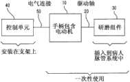
图2显示具有一电动机的粥样斑块切除术装置的一框图;Figure 2 shows a block diagram of an atherectomy device with an electric motor;
图3是示例性控制单元和手柄的平面图;Figure 3 is a plan view of an exemplary control unit and handle;
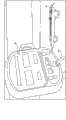
图4是控制单元的正视图;Fig. 4 is the front view of control unit;
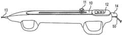
图5是手柄的平面图;Fig. 5 is the plan view of handle;
图6是图5手柄的俯视图;Fig. 6 is the top view of Fig. 5 handle;
图7是驱动轴远端的俯视图,驱动轴的远端超出导管的远端;Figure 7 is a top view of the distal end of the drive shaft, the distal end of the drive shaft protruding beyond the distal end of the catheter;
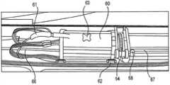
图8是图5和图6手柄的俯视图,为了清晰,其被打开了;Figure 8 is a top view of the handle of Figures 5 and 6, opened for clarity;
图9是图8手柄中的底座的特写图(close-up view);Figure 9 is a close-up view of the base in the handle of Figure 8;
图10是气体涡轮机在远端受阻时,驱动轴的远端的力矩随时间变化的曲线图;Fig. 10 is a graph showing the torque of the distal end of the drive shaft as a function of time when the gas turbine is blocked at the distal end;
图11是电动机在远端受阻时,驱动轴的远端的力矩随时间变化的曲线图;Fig. 11 is a graph showing the torque at the far end of the drive shaft as a function of time when the motor is blocked at the far end;
图12显示具有一电动机的粥样斑块切除术装置的一框图。Figure 12 shows a block diagram of an atherectomy device with an electric motor.
具体实施方式Detailed ways
本发明公开了一种冠状动脉旋磨术装置,其由电动机驱动旋转。在一些设计中,该装置包含一些气体涡轮驱动系统中不可用的功能,如未手柄特定模式而预设的存储在内存中的低/中/高旋转速度,计算盐水在静脉注射袋子中的剩余量以及当它变得足够低时发出相关的警告,和自动调整静脉注射泵速到一预定的速度或计算当马达转速改变时的水平。电动机具有相对于一可比的气体涡轮机具有更多的旋转惯量,因此该系统包括一控制机制,它有助于防止过大的转矩施加到驱动轴的远端。当通过马达旋转速度的下降,在远端检测到一阻塞时,马达将被断开,并允许其如飞轮般自由转动。该自由转动的马达允许该系统的大的角动量迅速而安全地耗散,而没有过大的转矩输送到驱动轴上。The invention discloses a coronary artery rotational atherectomy device, which is driven to rotate by a motor. In some designs, the unit contains some functions not available in gas turbine drive systems, such as low/medium/high rotation speeds stored in memory preset without handle specific mode, calculation of saline remaining in the IV bag volume and an associated warning when it gets low enough, and automatically adjusts the IV pump speed to a predetermined speed or calculates the level when the motor speed changes. Electric motors have more rotational inertia relative to a comparable gas turbine, so the system includes a control mechanism that helps prevent excessive torque from being applied to the distal end of the drive shaft. When an obstruction is detected at the distal end by a drop in motor rotational speed, the motor will be disconnected and allowed to spin freely like a flywheel. The free turning motor allows the high angular momentum of the system to be quickly and safely dissipated without excessive torque being delivered to the drive shaft.
同时也公开了一不太复杂的粥样斑块切除术装置,其缺乏上述一些更精密的控制功能。这个更为简单的装置可包括一带有机载(on-board)固件的电动机,一马达驱动器和一可重复使用的盐水泵,但缺少精密的软件控制。这类装置可以以更低的成本制造,并可以以比具有更精密控制元件的装置低的成本出售。A less complex atherectomy device is also disclosed which lacks some of the finer control features described above. This simpler setup could include an electric motor with on-board firmware, a motor driver and a reusable brine pump, but lacks sophisticated software control. Such devices can be manufactured at a lower cost and sold at a lower cost than devices with more sophisticated control elements.
前面一段所述仅仅是一个概要,且不应解释为对本发明的任何限制。更详细的描述如下。The preceding paragraph is merely a summary and should not be construed as any limitation of the invention. A more detailed description follows.
图1是一个通常已知的冠状动脉旋磨术装置的示意图。该装置包括手柄部10,细长的、柔性的驱动轴20,驱动轴20具有偏心膨大研磨头28,以及从手柄部10向远端延伸的细长的导管13。如本领域技术人员所知的,驱动轴20由螺旋盘绕的线构成,研磨头28固定在其上。导管13具有腔,其中容纳有驱动轴20的大部分长度,除了膨大研磨头28和膨大研磨头28远端短部件。驱动轴20同样含有一个内腔,使得驱动轴20可沿着导线15推进和旋转。可设置液体补给线17以将冷却的和润滑的液体(一般为盐水或另一种生物相容的液体)引入导管13。Figure 1 is a schematic diagram of a generally known rotational atherectomy device. The device includes a
手柄部10优选包含涡轮(或类似的旋转驱动机构),以高速旋转驱动轴20。手柄部10一般可连接到动力源,比如通过管16输送的压缩空气。一对光纤电缆25、或者单一光纤电缆,则可能被使用,还可提供用于监控速度的旋转的涡轮和驱动轴20(关于这种手柄和相关的仪器的详细内容在业界都知道,并且在例如,授权给Auth的美国专利5,314,407号中有描述,以上专利的全文以引用的方式并入本文中)。手柄部10还优选包括控制按钮11,以相对导管13和手柄部壳体推进和缩回涡轮和驱动轴20。The
图1中的研磨组件28是一个附在驱动轴20上并靠近驱动轴20远端的偏心实心研磨头。术语“偏心”在此处表示,研磨头的质心横向偏离驱动轴20的旋转轴线。当驱动轴高速旋转时,研磨头的偏离的质心造成研磨头旋转时,驱动轴在接近研磨头处径向向外弯曲,从而使研磨头能磨损比其静止直径更大的直径。偏心实心研磨头详细公开在,例如,Thatcher等人在2007年6月11日提交的美国专利申请,申请号为11/761,128,名称为Eccentric abrading headfor high-speed rotational atherectomy devices,公开于2008年12月11日,美国专利号US2008/0306498,以上专利的全文以引用的方式并入本文中。Grinding assembly 28 in FIG. 1 is an eccentric solid grinding head attached to drive
本申请主要针对在手柄中的一个电动机,其基于图1的空气或氮气驱动涡轮机进行改进。在这方面,许多或所有其他已知图1的粥样斑块切除术装置的组件,包括导管13、导线15、手柄部10上的控制按钮11、螺旋盘绕的驱动轴20和偏心实心研磨头28,都可以与本专利公开的研磨头设计配套使用。This application is mainly directed to an electric motor in the handle, which is based on the improvement of the air or nitrogen driven turbine of Fig. 1 . In this regard, many or all other known components of the atherectomy device of FIG. 28, can be used in conjunction with the grinding head design disclosed in this patent.
该电气设备可以包含有多种功能的组合。两种这种情况在下面的图和文字中描述。第一种情况具有相对较少功能,而第二种情况具有更多的功能。每一种都有其自己的优势。例如,具有相对较少功能的装置的生产比相对功能完善的装置更加便宜,并更容易销售和推广。同样的,具有很多功能的装置可以销售和推广成一高性能装置,它可以比相对没有功能的装置赢得更高的价格。它们两个都在下面详述,首先是具有较少功能的设备。The electrical equipment may contain a combination of functions. Two such cases are depicted in the figures and text below. The first case has relatively few functions, while the second case has more functions. Each has its own advantages. For example, devices with relatively few functions are cheaper to produce, and are easier to sell and market than devices with relatively complete functions. Likewise, a device with many functions can be sold and promoted as a high-performance device, which can command a higher price than a device with relatively no functions. Both of them are detailed below, starting with the device with fewer features.
图12是具有一电动机和相对较少功能的粥样斑块切除术装置的一框图。Figure 12 is a block diagram of an atherectomy device with a motor and relatively few functions.
控制单元140是该装置的非一次性部分,其可以在一个个程序中重复使用。该控制单元可安装在一支架上,如图12所示,或可作为一独立的装置放在工作台面上。The
该控制单元140具有连接手柄110的一电气连接150。在许多例子中,该控制单元140充当手柄110中的马达的电源供应器,而电气连接150不超过两个电流所需的导电组件(或,任选地,如果使用独立的接地线,三个)。通常地,该控制单元140提供给手柄110一可控制的并可调的直流电压,使用不同的电压以开环的方式控制手柄110中马达的转速。请注意,也可以使用交流电压。对于这种简单的电气连接150,在手柄110和控制单元140之间不可能进行通信;该控制单元140简单地给手柄110的马达供能。请注意,在其他情况下,该电气连接150可以更为精密,并可包括一种或两种在控制单元140和手柄110之间通信的方法;这种情况在下面相对功能完善的装置中描述。The
该控制单元140还包括一可重复使用的盐水泵。这种泵以一预定的速率从袋子中引导盐水,或其他合适的来源中,通过一盐水连接190到手柄110。手柄110中的合适的水管装置引导盐水到导管中,其充满驱动轴周围的空间,并有助于润滑和清洁系统。至少,该控制单元140需要调整盐水泵入手柄的速率,而且需要通知操作者泵的状态。这两个功能在下面描述。The
盐水泵至少使用两个泵速,其通常被指定为“低”和“高”。通常地,低速和高速是硬编码在控制单元140的固件中。作为替换,可以使用多于两个不连续的泵速,和/或可以使用一个连续改变的泵速。通常地,在程序的开始时,驱动轴开始快速旋转前,低泵速用于冲洗系统。通常地,当驱动轴快速转动时,高泵速用于程序运作期间。在一些情况下,泵速在高速和低速之间自动变化,这取决于控制单元上的电源供应设置和/或手柄中马达所需的旋转速度。在一些情况下,在每个程序开始时,使用者被指示以低流速启动泵,等待一特定的时间后,将流速调至高速。Brine pumps use at least two pump speeds, which are usually designated "low" and "high". Typically, low speed and high speed are hardcoded in the firmware of the
该装置可使用一重量传感器,用于监控盐水的水平。这种重量传感器可以是一弹簧般的装置,盐水袋悬挂其上。如果该袋子的悬挂重量及其容量降低到预先确定的阈值,则触发重量传感器中的开关。盐水一般以标准尺寸的袋子送来,如200毫升,然而也可以使用任何尺寸的袋子。重量传感器也可将其用在如平台般的装置上,而盐水袋放置其上。如果袋子的重量降低到一预定的水平,则泵关闭,马达断电(为了防止来自于正在运行的设备上因没有盐水而造成的损坏装置和损伤病人),并通知操作者。The device may use a weight sensor for monitoring the level of saline. This weight sensor can be a spring-like device from which the bag of saline is suspended. If the bag's hanging weight and its capacity drop below a predetermined threshold, a switch in the weight sensor is triggered. The brine is typically delivered in standard sized bags, such as 200ml, however any size bag can be used. The weight sensor can also be used on a platform like device on which the saline bag is placed. If the weight of the bag drops to a predetermined level, the pump is turned off, the motor is de-energized (to prevent damage to the device and injury to the patient from running equipment without saline), and the operator is notified.
操作者通过控制单元获知泵系统的状态。一种简单的通知系统在下面详细介绍,然而,可以使用任何合适的通知系统。The operator is informed of the status of the pump system through the control unit. A simple notification system is detailed below, however, any suitable notification system may be used.
在这简单的通知系统中,该状态是由三个不同颜色的发光二极管(LED)提供。“绿色”灯表示泵正常运行,且手柄正常供电。设有一内部电路,其用于监控手柄的48伏电源供应。“黄色”灯表示系统出现某些错误;一个门打开了,或存在一些其它可修复的系统故障。“红色”灯表示袋子中的盐水用完了。可以理解的是,也可以使用其他指示系统。In this simple notification system, the status is provided by three light-emitting diodes (LEDs) of different colors. A "Green" light indicates that the pump is operating normally and the handle is receiving power. There is an internal circuit that monitors the handle's 48 volt power supply. A "yellow" light indicates that something is wrong with the system; a door is open, or there is some other repairable system failure. A "red" light indicates that the bag has run out of salt water. It will be appreciated that other pointing systems may also be used.
该控制单元140通常包括一累积时间监控器,确保装置的总操作时间不超过一预定的阈值,如9分钟。也可以使用其他预定的时间阈值。通常,一旦已经达到累积工作时间,该控制装置140会发出警告和/或使马达停止。The
在一些替代的设计中,该电动机布置在控制单元140中,而不是在手柄110中,而电气连接150被替换为机械连接以转移马达的旋转到驱动轴。In some alternative designs, the motor is arranged in the
本文的其余部分将介绍相对功能完善的装置,其中包括大多数或所有图12装置的功能,此外还有许多图12装置中没有的功能。The remainder of this article presents relatively fully functional devices that include most or all of the functionality of the Figure 12 device, in addition to many features that are not present in the Figure 12 device.
开始,图2显示具有电动机的粥样斑块切除术装置的一框图。To begin, Figure 2 shows a block diagram of an atherectomy device with a motor.
一控制单元40(也称为控制器)是该装置的非一次性的部分,并包括大部分与驱动马达不直接相关的装置的电气功能。例如,该控制单元40可以识别插入了哪种类型的手柄,包括用于设置马达所需转速的控制功能,包括控制泵输送盐水到导管的功能。A control unit 40 (also called controller) is a non-disposable part of the device and includes most of the electrical functions of the device not directly related to the drive motor. For example, the
该控制单元40具有连接手柄10的一电气连接50。除了具有控制旋钮和能相对于导管推进和缩回研磨组件的相关机械结构外,手柄10包括实际的电动机和马达与驱动轴20的机械联轴器。The
该驱动轴20从位于手柄10中的与马达连接的机械联轴器上延伸,经导管到达病人的脉管系统。驱动轴20的近端(近)布置在手柄10中,而驱动轴20的远端(远)延伸到血管内的阻塞。一研磨组件30连接到驱动轴20,或与其一体成型,并位于或靠近驱动轴的远端。The
手柄10、导管以及驱动轴20都是设计成一次性使用的,并一旦完成此程序就处理掉。操作者保留该控制单元40,以将来重复使用。The
作为替代,电动机本身可布置在控制单元40中,而不是在一次性使用的手柄10中。马达设置在控制单元40中就需要在该控制单元40和手柄50之间增加一个机械的联轴器。手柄仍包括用于推进和缩回导管中的研磨组件的控制旋钮11。Alternatively, the motor itself may be arranged in the
图3是示例性控制单元40和手柄10的平面图。在这个例子中,电气连接50从控制单元40的前面出来,并进入手柄10在图3视图中的右侧。导管和驱动轴连接至手柄10的左侧,且没有清楚地显示在图3的视图中。FIG. 3 is a plan view of an
下面描述许多的装置的功能,为方便同时对它们对应的在控制单元40上的控制功能进行描述。可以理解的是,对于描述的功能,任何合适的控制功能,连同任何合适的在控制单元40上布局都可以使用,而附图中所示的控制功能仅仅是示例。The functions of many devices are described below, and their corresponding control functions on the
图4是控制单元40的正视图。控制单元的后部可以放置工作台面上,夹在支架上,悬挂在杆上,或具有另一种合适的安装方式。在一些情况下,控制单元是由静脉输液架支撑,这样,静脉输液盐水可以悬挂在同一个架更高的地方,并流入控制单元40上的泵。FIG. 4 is a front view of the
从上往下看,最上面的组件是通知屏幕41,它可以显示文本和字符信息。例如,该屏幕41可以显示各种组件的状态,如“盐水泵关闭”。另一个例子是,当一特定的手柄插上时,该控制器单元40可以识别它,并显示其名称及有关信息在通知屏幕41上。再如,该“通知”屏幕41也可以为医生显示错误和故障排除的信息。Viewed from above, the uppermost component is the
运行速度42是驱动轴近端的实际旋转速度,单位是1000RPM(每分钟转数)或kRPM。运行速度42通常每秒更新数次,以及在一些情况下可以显示在相对大的LED中,其让医生很容易看见。通常,旋转速度可达200kRPM。The
旋转速度可由电动机本身获得。例如,电动机可包括一个或多个霍尔效应传感器,其在马达旋转通过一特定点时每次产生一个电信号。该旋转速度与是信号的速度成正比,或等效地,与信号之间的时间间隔成反比。替代地,可以使用任何合适的传感器和信号。The speed of rotation can be obtained by the motor itself. For example, a motor may include one or more Hall effect sensors that generate an electrical signal each time the motor rotates past a certain point. The speed of rotation is directly proportional to the speed of the signal, or equivalently, inversely proportional to the time interval between signals. Alternatively, any suitable sensors and signals may be used.
实际运行速度42的下面是所选速度43,也显示为kRPM。在操作过程中,控制单元40和/或手柄10中的控制电路(反馈回路)调整电动机的电流和/或电压以保持实际运行速度42尽可能接近所选速度43。Below the
事件时间44是装置的一特定运行所经过的时间。通常地,该事件时间44显示为分:秒,然而可以使用任何合适的单位。
该事件时间44下面是总时间45,这是特定装置已运行的累积总时间45。对于这种测量的目的将在下文解释。Below this
在一特定的时间调整粥样斑块切除术装置的速率是通常的做法,如9分钟,超过这个时间不建议使用。换言之,装置在整个操作过程中可以反复启动和关闭。只要总的装置实际启动的累积时间不超过一特定的值,例如9分钟,这种关闭和启动的切换是可以接受的。通常地,该手柄10包括存储累积的工作时间的电子设备,然而这种数据可替代地存储在控制单元40中。It is common practice to adjust the rate of an atherectomy device for a specific time, such as 9 minutes, beyond which time is not recommended. In other words, the device can be turned on and off repeatedly throughout operation. This switching off and on is acceptable as long as the cumulative time the total device is actually on does not exceed a certain value, eg 9 minutes. Typically, the
如果总运行时间45触及该阈值时,该控制单元或者关闭,或者发出警告提示医生已达到工作时间限制。在一些情况下,医生可以撤销该限制。在其他情况下,达到该会使马达停止,这样,不能再使用该装置。If the total operating time 45 hits this threshold, the control unit either shuts down or issues a warning that the doctor has reached the working time limit. In some cases, a doctor can revoke this restriction. In other cases, reaching this point will stop the motor so that the device can no longer be used.
四个速度和时间显示的右边是泵46,其从外部的静脉注射袋60接收盐水并通过液体供应管17引导到手柄10中(见图1)。一旦进入手柄10,盐水被引导进入导管13,在这里,它帮助润滑驱动轴、冷却研磨头,和冲掉所有碎片。To the right of the four speed and time displays is the pump 46 which receives saline from the
应当注意到,一般来说,自液体供应管17的盐水往往会渗漏出大量在手柄内。这种渗漏,虽然很麻烦,但有助于润滑和冷却马达及手柄的内部结构,这是有利的。渗漏的本身是源于手柄中同心管和重叠管之间的细微缝隙,这形成了密封。如果这些管制造成配合得太牢固,渗漏就会减少,但管与快速旋转的驱动轴之间的摩擦将会惊人的大。对于在这里显示和描述的该电动机装置展示的管,仅在较早的小部分早期一代装置中会渗漏,但仍会渗漏有限的量,并且是有利的。It should be noted that, in general, saline water from the
盐水从静脉注射袋60流出,通过一管61到泵47,离开该泵后通过一中间管62,穿过一缝隙检测器48,并随着液体供应管17流出缝隙检测器48(见图1)。Saline flows from the
该缝隙检测器48包括一光发射器,例如一发光二极管,使光照射通过中间管62,以及一光探测器直径地面对发射器,接收从来自发射器的光线。在正常操作期间,当盐水连续不断地通过中间管而没有任何气泡,到达光探测器的光具有一特定的大致不变的亮度。如果气泡的边缘在中间管62中经过,到达光=探测器的光就会被中断,而光检测器输出变化的值。这个值的变化表示,在盐水管路中存在气体(一“缝隙”),并由控制器40用来关闭泵47,为的是防止该缝隙找到进入病人体内的路径。The
按钮“泵电源”51开关泵的电源,从启动到关闭,或从关闭到启动。如果泵启动,在按钮上或附近的一LED或其他指示器会亮起。Button "Pump Power" 51 switches power to the pump from on to off, or from off to on. An LED or other indicator on or near the button will light up if the pump is activated.
如果泵不是已经启动的,按钮“准备”52用于打开泵,并且当该按钮按下时,设置泵的流量至高。该“准备”功能用于冲洗泵系统,并将所有空气从系统中赶出。通常地,该泵准备根据需要被间歇性地使用。The button "Ready" 52 is used to turn on the pump if it is not already primed, and when the button is pressed, sets the pump flow to high. This "prepare" function is used to flush the pump system and force all air out of the system. Typically, the pump is intended to be used intermittently as needed.
这三个“速度选择”按钮标记为“低”、“中”和“高”,每个上面有一指示灯对应于所选的速度。一般来说,对于一特定型号的手柄10插入到控制单元40中,就有由制造商确定的预设的速度。这些速度由控制单元40自动识别,这样,医生就不需要手动输入它们。这种识别可以由,例如,手柄10上预设速度的存储器,控制单元40上查找表中的预设速度存储器,和/或通过中央数据库(例如因特网)预置速度的按需查找进行。The three Speed Select buttons are labeled Low, Medium, and High, and each has an indicator light corresponding to the selected speed. Generally, for a particular model of
如果医生希望取得比由默认的低/中/高预置提供的更多的速度精密控制,则增量按钮54可以通过一预定的增量向上或向下调整所选的速度,如10kRPM,然而也可以使用任何合适的增量。If the physician wishes to obtain more fine control of the speed than provided by the default low/medium/high presets, the
当一新的静脉注射袋连接到泵时,使用“重设静脉注射袋”按钮55。在一些例子中,系统将提示用户输入静脉注射袋的尺寸。在其他例子中,使用一标准尺寸的静脉注射袋。该控制器40随着时间的推移监视泵速,并能有效地执行相对于时间的泵速积分,计算出已经从袋子中泵出多少盐水,且同样地,计算出有多少盐水留在袋子中。当袋子中的盐水量下降到低于一预先确定的阈值时,该控制器40通过发出声音,闪烁灯,或其他合适的通知方式,给使用者发送通知。The "Reset IV Bag"
请注意,并没有对泵47的泵速(或流量)的手动控制。一般来说,该泵速在工厂时已确定,并且对每个旋转速度(低/中/高),对手柄10的每种型号标准化。这一预先确定的泵速可以存储在嵌入手柄10中的电子设备的查找表中,可以存储在嵌入控制单元40中的电子设备的查找表中,可以由控制单元40中的电子设备实时计算出来,可以从中央数据库中实时查找到,例如,通过互联网,或任意以上的组合。Note that there is no manual control of
通常地,仅当有东西卡住的时候,才使用“制动优先”按钮56。在正常使用的情况下,导线仍然从手柄延伸,通过驱动轴的中心,经过研磨组件,并超过阻塞。然后,驱动轴绕导线旋转。在使用过程中,导线仍旋转地保持固定不动,并且在手柄10中有一“制动”用于旋转地锁定并阻止它旋转。有时,可能会出现有东西卡住,无论是在导管本身中,在驱动轴的远端,或超过驱动轴的远端。当有东西卡住时,使用者可以按下“制动优先”按钮56,以允许导线以一非常低的转速旋转。在一些情况下,导线和驱动轴一样以相同的低转速旋转。在其他情况下,导线独立于驱动轴的转速旋转。通常地,只要按住制动优先按钮56,导线旋转。Normally, the "brake override"
图5是一典型的手柄10的平面图。电气连接50从控制单元40进入手柄10中图5的右侧。导管和驱动轴在图5的左边离开手柄10。就控制器来说,控制功能的布局仅仅是示例性的,可以使用其他合适的布局。FIG. 5 is a plan view of a
控制旋钮11相对于导线和导管纵向平移驱动轴,其中,导线和导管保持固定不动。该旋钮11沿一通道有一约15厘米的行程范围。该控制旋钮11在程序运作期间被广泛地使用,在这期间,医生定位和重新定位快速旋转的研磨头以完全清除血管中的阻塞。The
该控制旋钮11也可以包括一可选的启动/关闭开关按钮,其可以启动和关闭手柄中的电动机。The
手柄10可以包括一套重复的速度选择按钮12,其重复控制器上的对应的按钮53的功能。手柄10本身上具有速度选择按钮12对医生来说是一个很大的方便。The
杠杆14是导线的一制动器,当结合时,它可防止导线随着驱动轴旋转而转动。在一些情况下,当杠杆处于水平时,该导线制动14已锁定,如图5,而当医生向上拉时,解锁。
图6是图5手柄10的俯视图。除了显示控制旋钮11、速度选择按钮12和导线制动14外,图6还显示了电气连接50,其通常是14英尺长的电缆,然而也可以使用其他合适的长度,并显示导管13,其通常用一应变消除接头连接到手柄10的主体。驱动轴20的远端可见于图6,并在图7中更详细显示。FIG. 6 is a top view of the
图7是驱动轴20的远端的俯视图,其超出导管13的远端。通常地,该驱动轴20是一螺旋缠绕的线圈,然而可以使用任何适当的机制来从电动机传递扭矩到研磨组件28,以充当一驱动轴。例如,一替代的驱动轴可以是有缝或无缝的塑料或金属管。FIG. 7 is a top view of the distal end of the
图7所示的研磨组件28是驱动轴20的一膨大部分,该膨大部分的外部涂层有研磨材料。替代地,可以使用任何合适的研磨组件,包括具有一质心的组件(所谓的“研磨头”),其从驱动轴的旋转横向移位(所谓“偏心的”研磨头),并具有研磨的外部。通常地,该偏心实心研磨头连接在驱动轴上,然而它可以替代地与驱动轴一体化成型。通常地,该偏心实心研磨头连接到驱动轴的远端的附近,但不是在其上,然而它可以替代地连接到驱动轴的远端上。Abrasive assembly 28 shown in FIG. 7 is an enlarged portion of
图8是手柄10的俯视图,为了清晰,其被打开了。图9是图8中手柄10的底座的近视图。实际上,在程序之前、期间和之后手柄仍然是闭合的。如同图5和图6,导管13和驱动轴20在图8的视图中退出手柄10的左边缘。Figure 8 is a top view of the
电动机本身布置在底座60中。底座60的外部充当马达的一散热器。马达由一系列的电气连接61供电,其连接到电气连接50,继而接到控制单元的40。The electric motor itself is arranged in the
马达可以在纵向上平移15厘米的范围,并达到这样安装在车轮62上,车轮接合到手柄中各自的轨道。或者,可以使用其它平移机制。通常地,手柄用于一单一的程序,然后处理掉,所以车轮和轨道应当坚固,但一般不需要设计成一特别长的使用寿命。The motors can translate longitudinally over a range of 15 cm and are thus mounted on
底座的顶部具有一可选的启动/关闭切换开关63,其对应于控制旋钮上11上的关闭/关闭按钮。在使用过程中,该控制旋钮11位于切换开关63的正上方,并且医生可按下旋钮11来启动和关闭马达。The top of the base has an optional on/off
可以有一个或多个齿轮64提高或降低马达和驱动轴之间的旋转。例如,马达本身可能只有一个最大转速的50kRPM,而一系列不同尺寸的齿轮可以提高驱动轴的旋转4倍,达到200kRPM。There may be one or
具有齿轮系统的一个好处是,导线可以穿过齿轮的中心,而不是穿过马达的中心。这简化了该机械系统。One benefit of having a gear system is that the wires can go through the center of the gear instead of the center of the motor. This simplifies the mechanical system.
组件65是另一个启动/关闭开关,与切换开关63非常类似。但是,一个不同之处是,该开关65是连接到导线制动杠杆14。当该制动被松开时,该水平处于向上位置,不管任何其他启动/关闭开关的状态,开关65关闭马达。当该制动被接合时,开关65允许任何其他开关切换马达启动和关闭。开关65的伴随电路也位于或靠近手柄在图8中的最右边缘。
组件66、67和68涉及保持快速转动的驱动轴的受控和稳定的机械方面,以及确保功能性密封来充分地使液体受控。组件66和67是伸缩式机制的,例如同心的海波管,其足够紧以提供充分的密封,并且具有足够的弹性以使它们不会因为过大的摩擦而夺去转矩系统。
如上所述,手柄10的内部不是一个完全干燥的系统。蒸汽及渗漏液体(盐水)有助于冷却马达和其他在手柄仲及导管中的移动部件。系统的前支脚(图8中最左的支脚)可以是空心和开放的,这样,液体就能收集在其中。系统的后支脚(图8中最右的支脚)可以包括手柄的CPU,其可密封在多种泡沫和胶水之间,以使它不会在使用中弄湿。As noted above, the interior of the
该马达和齿轮转动驱动轴高达200kRPM,可在手柄中产生明显的震动。一般来说,这些震动是不利的,并且通常更好的做法是尽可能抑制这些震动。该伸缩部分从手柄的近端边缘延伸到底座,并从底座延伸到手柄的远端边缘,具有它们自己的谐振频率。该部分的谐振频率能够改变,这取决于底座实际上平移到范围内的什么地方。其结果是,在使用中完全避免谐振频率一般是很困难的或者不可能的。抑制谐振频率的一大范围震动的一个方法是在底座和伸缩装置之间的联轴器中使用一个或多个应变消除装置68。This motor and gear turns the drive shaft up to 200kRPM, which creates a noticeable jolt in the handle. Generally, these vibrations are undesirable, and it is often better to suppress them as much as possible. The telescoping sections extend from the proximal edge of the handle to the base, and from the base to the distal edge of the handle, having their own resonant frequency. The resonant frequency of this part can change depending on where in the range the base actually translates. As a result, it is generally difficult or impossible to completely avoid resonant frequencies in use. One way to dampen vibrations over a wide range of resonant frequencies is to use one or
我们已经描述了电动机和控制器的机械结构,下面首先谈谈无法预料的障碍,然后谈谈用电动机替换已知气体涡轮机电意外好处。Now that the mechanics of the electric motor and controller have been described, let's talk first about unforeseen obstacles and then about the electromechanical unexpected benefits of replacing known gas turbines with electric motors.
已知的气体涡轮机通常很小,塑料块,它可以利用空气压力加速至200kRPM。涡轮机本身一般都比较小,容易操作并且有令人满意的机械特征,但涡轮机的空气压力控制系统价格高昂,体积笨重,而且机械十分复杂。对于以电动机替换一旧的气体涡轮机呈现出一些设计和控制上的挑战。Known gas turbines are usually small, plastic blocks, which can be accelerated to 200kRPM using air pressure. The turbines themselves are generally small, easy to handle and have satisfactory mechanical characteristics, but the air pressure control systems for the turbines are expensive, bulky and mechanically complex. Replacing an old gas turbine with an electric motor presents several design and control challenges.
首先,电动机的旋转惯性可比小小的塑料气体涡轮机高达10倍,或更多。这就给控制电动机的控制系统提出了严峻的挑战;只使用旧的涡轮机的控制系统将无法正常工作。First, the rotational inertia of an electric motor can be as much as 10 times that of a small plastic gas turbine, or more. This presents a serious challenge to the control system that controls the electric motor; a control system that just uses the old turbine won't work.
一典型的气体涡轮机的控制系统是这样的。涡轮机上的一光纤给控制系统提供实际的转速,以周期性地调节气体的压力来使旋转速度与预定的速度相匹配。该控制系统可以将压力调整到一特定的阈值,如64psi。如果该涡轮机在某一时间长度内(如4秒)没有以其预定的旋转速度转动,该控制系统会假定有东西阻碍了研磨组件的旋转,因此压力设置为零,并且涡轮机停止。同样地,如果光纤检测到涡轮机停止运行,该控制系统会假定驱动轴的远端被缠住了,因此压力也设置为零。A typical gas turbine control system looks like this. A fiber optic on the turbine provides the actual rotational speed to a control system that periodically adjusts the gas pressure to match the rotational speed to a predetermined speed. The control system can adjust the pressure to a specific threshold, such as 64psi. If the turbine does not turn at its predetermined rotational speed for a certain length of time (eg, 4 seconds), the control system assumes that something is blocking the rotation of the grinding assembly, so the pressure is set to zero, and the turbine stops. Likewise, if the fiber optic detects that the turbine is stalled, the control system assumes that the distal end of the drive shaft is tangled, so the pressure is also set to zero.
当这样的关机发生时,检测在驱动轴的远端的研磨组件所经受的转矩是有利的。特别地,考虑到驱动轴的远端被缠住,并且忽然停止工作的情况。When such a shutdown occurs, it would be advantageous to detect the torque experienced by the grinding assembly at the distal end of the drive shaft. In particular, consider the case where the distal end of the drive shaft becomes entangled and suddenly stops working.
最初,就在被缠住后,研磨组件上就没有了转矩。从这个零值开始,因为涡轮机和整个驱动轴都在转动,转矩急剧上升,此时远端的远端仍然是卡住了。Initially, right after being entangled, there was no torque on the grinding assembly. From this zero value, as the turbine and the entire drive shaft are turning, the torque ramps up dramatically, at which point the distal end is still stuck.
最终,当驱动轴暂时地静止不动时,出现了转矩峰值。在此峰值,通过成角度地压缩驱动轴至其最压缩状态,所有驱动轴之前的旋转的角动量都转换成转矩。Eventually, a torque peak occurs when the drive shaft stands still momentarily. At this peak, the angular momentum of all previous rotations of the drive shaft is converted into torque by angularly compressing the drive shaft to its most compressed state.
超出这一峰值,由于一些角度压缩量在涡轮机上往后推,转矩开始下降。在这一阶段,驱动轴的远端仍然静止不动(因为它被卡住了),而驱动轴的其他部分,其往后延伸到其在涡轮机上的近端,以相反的方向转动,如同上述第一阶段。Beyond that peak, torque starts to drop off as some angular compression pushes back on the turbo. At this stage, the distal end of the drive shaft remains stationary (because it is stuck), while the rest of the drive shaft, which extends back to its proximal end on the turbine, turns in the opposite direction, as the first stage above.
最终,该角度压缩量耗散,并且转矩达到稳定时期。在这平稳时期,驱动轴自始至终静止不动,但是被涡轮机的角向力(转矩)成角度地压缩在一稳定状态。该平稳时期的转矩值大于零,但小于上述的第一峰值。使用上述这种控制机制,转矩保持在这个平稳值大约4秒钟(减去上升和稳定的时间,其都在毫秒的范围内),然后输送到涡轮机的气体压力被关闭。Eventually, this angular compression dissipates and the torque reaches a plateau. During this plateau, the drive shaft is stationary throughout, but is angularly compressed in a steady state by the angular force (torque) of the turbine. The torque value during this plateau is greater than zero, but less than the above-mentioned first peak value. Using this control mechanism as described above, the torque is held at this plateau value for about 4 seconds (minus ramp up and settling time, which are both in the millisecond range), before the gas pressure to the turbine is shut off.
这都显示在图10的曲线中。大峰下面的交叉影线区域是马达的角动量,加上驱动轴的角动量以及任何组件的干预。对已知的气体涡轮机,这种值是可以接受的小,并不会造成任何问题。但是,对于电动机,马达本身比任何系统中的其他组件具有更多的角动量,并且这值能更大,大于10倍或更多。如果电动机使用相同的控制系统,大峰还会更加大,如果以马达的角动量衡量,比现在还要大10倍。这样大的转矩增幅,很可能会导致仪器损坏,或更糟的是,损伤病人的血管。这是不可接受的。This is all shown in the graph in Figure 10. The cross-hatched area below the large peak is the angular momentum of the motor, plus the angular momentum of the drive shaft and any component intervention. For known gas turbines, this value is acceptably small and does not cause any problems. However, with electric motors, the motor itself has more angular momentum than any other component in the system, and this value can be much greater, by a factor of 10 or more. If the motor uses the same control system, the peak will be even larger, 10 times larger than it is now if measured by the angular momentum of the motor. Such a large torque increase is likely to cause damage to the instrument, or worse, damage the patient's blood vessels. This is unacceptable.
一种处理大的角动量的问题的方法是,改变马达一旦检测到阻塞后的处理方式。对于已知的气体涡轮机,等待4秒然后切断气体压力输送到涡轮机是足够的。但是,对于电动机,在这4秒内有可能是一个很大的伤害。One way to deal with the problem of high angular momentum is to change how the motor handles once it detects a jam. With known gas turbines, it is sufficient to wait 4 seconds and then cut off the gas pressure delivery to the turbine. However, with the motor, there is the potential for a lot of damage in those 4 seconds.
一种快速耗散电动机的角动量的方法显示在示意图11。A method for quickly dissipating the angular momentum of the motor is shown in
最初,装置正常工作。该马达施加一转矩到驱动轴的近端,驱动轴随着马达转动,并且驱动轴的远端一起转动。Initially, the device worked normally. The motor applies a torque to the proximal end of the drive shaft, the drive shaft rotates with the motor, and the distal end of the drive shaft rotates with it.
然后,该装置遇到一阻塞,其抓住驱动轴的远端,导致它停止旋转。图11上,这一点标记为“远端突然停止”。The device then encounters an obstruction which grabs the distal end of the drive shaft causing it to stop rotating. On Figure 11, this point is labeled "Far End Abrupt Stop".
驱动轴的远端停止,但马达继续旋转驱动轴的近端。该驱动轴开始卷绕(旋转地压缩),并且实现这种卷绕所需的转矩逐渐使马达慢下来。The distal end of the drive shaft stops, but the motor continues to rotate the proximal end of the drive shaft. The drive shaft begins to wind up (rotationally compress), and the torque required to achieve this wind up gradually slows the motor down.
一旦马达的旋转下降到低于一特定的阈值,该控制单元判断已经检测到一个阻塞,其中,该阀值可以是一个固定值,低于预定的旋转速度和/或从预定的旋转速度下降的百分比。该控制单元通过断开马达响应,使其能够如飞轮般自由转动。图11上,这种情况就发生在标有“检测到阻塞,马达设置为自由转动(没有转矩从马达输出)”。The control unit judges that a blockage has been detected once the rotation of the motor falls below a certain threshold, wherein the threshold can be a fixed value below and/or falling from a predetermined rotation speed percentage. The control unit responds by disconnecting the motor, allowing it to spin freely like a flywheel. On Figure 11, this happens on the line labeled "Block detected, motor set to freewheel (no torque output from motor)".
在自由转动的马达的角动量的影响下,该驱动轴继续卷绕(旋转地压缩)。在某一时刻,所有角动量的旋转动能都转换为旋转势能,并且驱动轴达到它的最紧密的缠绕点。The drive shaft continues to coil (rotationally compress) under the influence of the angular momentum of the freely rotating motor. At some point, all of the rotational kinetic energy of angular momentum is converted to rotational potential energy, and the drive shaft reaches its most tightly wound point.
该驱动轴随后松开,基本上将其所有的旋转势能转换成旋转动能,并以相反的方向旋转自由旋转的马达。图11上,这种情况就发生在标记为“驱动轴松开”的区域中。The drive shaft then unwinds, converting essentially all of its rotational potential energy into rotational kinetic energy, and spinning the free-spinning motor in the opposite direction. On Figure 11, this occurs in the area marked "Drive Shaft Released".
请注意,在这部分可能有一些振荡,其中,曲线在零附近伴随有随时间减少振幅的振荡(阻尼振动)。最终,该曲线在零处趋于稳定状态,此时,驱动轴基本上不缠绕并保持静止不动,且没有转矩施加到驱动轴的远端的末端。这是一个松弛的、稳定的状态,此时,所有的动能和势能已经通过摩擦和其他损失耗散掉。Note that there may be some oscillations in this part, where the curve is accompanied by oscillations that decrease in amplitude over time (damped oscillations) around zero. Eventually, the curve plateaus at zero, where the drive shaft is substantially unwound and remains stationary with no torque applied to the distal tip of the drive shaft. This is a relaxed, stable state where all kinetic and potential energy has been dissipated through friction and other losses.
请注意,图11的水平时间轴与图10中的不必要是一样的。实践中,图11的稳定时间是在毫秒级别。Note that the horizontal time axis of Figure 11 is not necessarily the same as that of Figure 10. In practice, the settling time of Figure 11 is on the millisecond level.
在图11中,有两个需要注意的数量。In Figure 11, there are two quantities to note.
第一,实线的峰值是施加到驱动轴的远端的最大转矩。如果这一最大转矩超过一特定值,则可能会损坏仪器,或更糟的是,损伤病人的血管。在实践中发现,该气体涡轮机的峰值(显示在示意图10中)足够低,不会造成任何损害。对于电动机(图11所示),该控制算法试图保持转等于或低于对于涡轮机在图10中所示的矩峰值,其具有这样的逻辑,如果这个转矩值对于涡轮机不产生任何问题,那么对于电动机也不应该出现任何问题。First, the peak value of the solid line is the maximum torque applied to the distal end of the drive shaft. If this maximum torque exceeds a certain value, it may damage the instrument, or worse, damage the patient's blood vessels. It was found in practice that the gas turbine peak (shown in schematic 10) is low enough not to cause any damage. For the electric motor (shown in Figure 11), the control algorithm tries to keep the RPM at or below the torque peak value shown in Figure 10 for the turbine, with the logic that if this torque value does not create any problems for the turbine, then There shouldn't be any problems with the motor either.
第二,该交叉影线区域代表电动机、驱动轴及其附带地连接组件的角动量。在实践中,电动机使其他方面的贡献完全失色。这个“曲线下的区域”对于一特定的马达和旋转速度来说,本质上是一固定的量,并且这是控制算法沿水平轴线“平滑处理”这一区域的工作,同时确保最大转矩不超过一特定值。电动机面临的挑战是,其交叉影线区域远远地比气体涡轮机的大,大10倍或更多。Second, the cross-hatched area represents the angular momentum of the motor, drive shaft, and its accompanying connected components. In practice, the electric motor completely overshadows other contributions. This "region under the curve" is essentially a fixed amount for a particular motor and rotational speed, and it is the job of the control algorithm to "smooth" this region along the horizontal axis while ensuring that maximum torque does not exceeds a certain value. The challenge with electric motors is that their cross-hatched areas are much larger than those of gas turbines, 10 times or more.
一旦成功解决处理增加的角动量的问题,使用电动机就有很多优势,而非气体驱动的涡轮机。Once the problem of handling the increased angular momentum is successfully resolved, there are many advantages to using electric motors rather than gas-driven turbines.
例如,一个优势是,各种量可以存储在控制单元40和/或手柄10的电子存储器中,如对一特定型号的手柄的低/中/高预设旋转速度,电动机的最大和/或最小旋转速度(即阈值,超出该值该装置会造成损害或失效),供应给电动机的最大和/或最小电流(多个阈值)、电动机的最大和/或最小输出转矩(依然是多个阈值)、性能指标(如对于一特定手柄的累计最长操作时间),以及静脉注射袋子的量(袋子尺寸,根据旋转速度的首选泵速,留在袋子中的液体量)。For example, one advantage is that various quantities can be stored in the electronic memory of the
与已知的气体涡轮机相比较,目前已拥有许多额外的量,如根据旋转速度的首选泵速。因此,电动机提供了大量新的、额外的功能,如当马达的旋转速度改变是,可以自动调整泵速至首选的水平。另一个新功能的例子是上文详细描述的“制动优先”功能,这在气体涡轮驱动的系统是完全不可用的。这个额外的功能是仅仅使用电动机而不是已知的气体涡轮机的意外的结果。Compared to known gas turbines, many additional quantities are presently available, such as a preferred pump speed as a function of rotational speed. Thus, the electric motor provides a number of new and additional functions, such as the ability to automatically adjust the pump speed to a preferred level when the rotational speed of the motor is changed. Another example of a new feature is the "brake override" feature detailed above, which is completely unavailable on gas turbine driven systems. This additional function is an unintended consequence of using only electric motors instead of known gas turbines.
另一个好处是,对于电动机,该控制单元40比控制气体压力驱动气体涡轮机的单元更为简单、不再繁琐、价格更低。此外,该装置采用电动机可以在使用时不需要在附近排布高压空气线。Another advantage is that, for an electric motor, the
在整个程序中,旋转速度、供应马达的电流以及供应马达的电压都可以改变,并且都可用于检测程序中特定的转折点。例如,在程序的开始部分,当需要刮掉的阻塞一坚硬的部分阻力很大,电动机需要较大的电流量来开始研磨。这一初始部分具有一较大的电流,一相对较低的转速匹配。随着程序的进展和一些阻塞被刮擦或磨光,马达需要较低的电流进行研磨。在这一阶段,电流下降,而马达的旋转速度保持基本不变或有所增加。如果粥样斑块切除术的尖端卡在阻塞中,则其旋转速度快速下降,而电流急剧上升。一般来说,至少一个旋转速度,马达电流和马达电压的改变可用于检测程序的特定的转折点。The speed of rotation, the current supplied to the motor, and the voltage supplied to the motor can be varied throughout the program and can be used to detect specific turning points in the program. For example, at the beginning of the program, when there is a lot of resistance to the clog-hard part that needs to be scraped off, the motor requires a higher amount of current to start grinding. This initial part has a larger current, matched with a relatively lower rotational speed. As the program progresses and some blockages are scraped or polished, the motor requires a lower current to grind. During this phase, the current drops while the rotational speed of the motor remains essentially the same or increases. If the atherectomy tip becomes lodged in the blockage, its rotational speed drops rapidly while the current rises sharply. In general, at least one change in rotational speed, motor current and motor voltage can be used to detect a specific turning point in the program.
本文对本发明及其应用的描述是说明性的,并不是为了限制这项发明的范围。对本文公开的实施例进行变形和修改是可行的,以及本领域的技术人员根据本专利文件理解后,实施例的可行的替代方案及各种因素的等同,应理解为本专利公开内容范围内。这些和其他本文公开的实施例的变形和修改没有偏离本发明范围和精神。The description herein of the invention and its applications is illustrative and not intended to limit the scope of the invention. It is feasible to deform and modify the embodiments disclosed herein, and after those skilled in the art understand this patent document, the feasible alternatives of the embodiments and the equivalent of various factors should be understood as within the scope of this patent disclosure . Variations and modifications of these and other embodiments disclosed herein are made without departing from the scope and spirit of the invention.
Claims (27)
Priority Applications (1)
| Application Number | Priority Date | Filing Date | Title |
|---|---|---|---|
| CN201610016469.3ACN105559856B (en) | 2010-02-26 | 2010-11-30 | Rotational atherectomy device with motor |
Applications Claiming Priority (3)
| Application Number | Priority Date | Filing Date | Title |
|---|---|---|---|
| US12/713,558US9050126B2 (en) | 2010-02-26 | 2010-02-26 | Rotational atherectomy device with electric motor |
| US12/713,558 | 2010-02-26 | ||
| PCT/US2010/058286WO2011106053A1 (en) | 2010-02-26 | 2010-11-30 | Rotational atherectomy device with electric motor |
Related Child Applications (3)
| Application Number | Title | Priority Date | Filing Date |
|---|---|---|---|
| CN201610015016.9ADivisionCN105640616A (en) | 2010-02-26 | 2010-11-30 | Rotational atherectomy device with electric motor |
| CN201610016469.3ADivisionCN105559856B (en) | 2010-02-26 | 2010-11-30 | Rotational atherectomy device with motor |
| CN201610016474.4ADivisionCN105640617A (en) | 2010-02-26 | 2010-11-30 | Rotational atherectomy device with electric motor |
Publications (2)
| Publication Number | Publication Date |
|---|---|
| CN102781353Atrue CN102781353A (en) | 2012-11-14 |
| CN102781353B CN102781353B (en) | 2016-02-24 |
Family
ID=44505694
Family Applications (4)
| Application Number | Title | Priority Date | Filing Date |
|---|---|---|---|
| CN201610016469.3AActiveCN105559856B (en) | 2010-02-26 | 2010-11-30 | Rotational atherectomy device with motor |
| CN201610016474.4APendingCN105640617A (en) | 2010-02-26 | 2010-11-30 | Rotational atherectomy device with electric motor |
| CN201080064853.1AActiveCN102781353B (en) | 2010-02-26 | 2010-11-30 | Rotary atherectomy device with electric motor |
| CN201610015016.9APendingCN105640616A (en) | 2010-02-26 | 2010-11-30 | Rotational atherectomy device with electric motor |
Family Applications Before (2)
| Application Number | Title | Priority Date | Filing Date |
|---|---|---|---|
| CN201610016469.3AActiveCN105559856B (en) | 2010-02-26 | 2010-11-30 | Rotational atherectomy device with motor |
| CN201610016474.4APendingCN105640617A (en) | 2010-02-26 | 2010-11-30 | Rotational atherectomy device with electric motor |
Family Applications After (1)
| Application Number | Title | Priority Date | Filing Date |
|---|---|---|---|
| CN201610015016.9APendingCN105640616A (en) | 2010-02-26 | 2010-11-30 | Rotational atherectomy device with electric motor |
Country Status (9)
| Country | Link |
|---|---|
| US (5) | US9050126B2 (en) |
| EP (1) | EP2538857B1 (en) |
| JP (4) | JP5855587B2 (en) |
| CN (4) | CN105559856B (en) |
| AU (1) | AU2010346575B2 (en) |
| CA (1) | CA2784946C (en) |
| DK (1) | DK2538857T3 (en) |
| ES (1) | ES2718107T3 (en) |
| WO (1) | WO2011106053A1 (en) |
Cited By (5)
| Publication number | Priority date | Publication date | Assignee | Title |
|---|---|---|---|---|
| CN113301862A (en)* | 2019-01-15 | 2021-08-24 | 波士顿科学有限公司 | Atherectomy System with Supply Line Accessories |
| CN113576559A (en)* | 2016-01-29 | 2021-11-02 | 直观外科手术操作公司 | Systems and methods for variable speed surgical instruments |
| CN115135259A (en)* | 2020-02-19 | 2022-09-30 | 波士顿科学国际有限公司 | High-power plaque removal system with multiple safety limits |
| CN115590583A (en)* | 2021-07-09 | 2023-01-13 | 苏州英途康医疗科技有限公司(Cn) | Electric planer and its control method, device and storage medium |
| WO2025102419A1 (en)* | 2023-11-17 | 2025-05-22 | 上海微创旋律医疗科技有限公司 | Rotary grinding apparatus, rotary grinding device, rotary grinding rotational speed acquisition method and apparatus, computer device, storage medium, and computer program product |
Families Citing this family (57)
| Publication number | Priority date | Publication date | Assignee | Title |
|---|---|---|---|---|
| JP5492583B2 (en)* | 2010-01-29 | 2014-05-14 | 日立コンシューマエレクトロニクス株式会社 | Video processing apparatus and video processing method |
| US9050126B2 (en)* | 2010-02-26 | 2015-06-09 | Cardiovascular Systems, Inc. | Rotational atherectomy device with electric motor |
| US9488467B2 (en)* | 2010-10-28 | 2016-11-08 | General Electric Company | System and method for monitoring in real time, a gap between portions in a machine |
| US10729458B2 (en)* | 2011-03-30 | 2020-08-04 | Covidien Lp | Ultrasonic surgical instruments |
| US20130253552A1 (en)* | 2012-03-20 | 2013-09-26 | Cardiovascular Systems, Inc. | Controller for an atherectomy device |
| US20140316449A1 (en)* | 2013-03-14 | 2014-10-23 | Cardiovascular Systems, Inc. | Devices, systems and methods for a quick load guide wire tool |
| US9750525B2 (en) | 2013-03-14 | 2017-09-05 | Cardiovascular Systems, Inc. | Devices, systems and methods for an oscillating crown drive for rotational atherectomy |
| US9936970B2 (en) | 2013-03-14 | 2018-04-10 | Cardiovascular Systems, Inc. | Devices, systems and methods for an oscillating crown drive for rotational atherectomy |
| US20140277014A1 (en)* | 2013-03-15 | 2014-09-18 | Cardiovascular Systems, Inc. | Rotational atherectomy device with biasing clutch |
| US9439674B2 (en)* | 2013-07-25 | 2016-09-13 | Cardiovascular Systems, Inc. | Rotational atherectomy device with exchangeable drive shaft and meshing gears |
| US20150080795A1 (en) | 2013-07-26 | 2015-03-19 | Cardiovascular Systems, Inc. | Devices, systems and methods for performing atherectomy and subsequent balloon angioplasty without exchanging devices |
| US9468457B2 (en) | 2013-09-30 | 2016-10-18 | Cardiovascular Systems, Inc. | Atherectomy device with eccentric crown |
| USD766433S1 (en) | 2013-11-04 | 2016-09-13 | Cardiovascular Systems, Inc. | Eccentric crown |
| US10052122B2 (en)* | 2014-01-17 | 2018-08-21 | Cardiovascular Systems, Inc. | Spin-to-open atherectomy device with electric motor control |
| US10271869B2 (en) | 2014-03-01 | 2019-04-30 | Rex Medical, L.P. | Atherectomy device |
| EP3116417B1 (en) | 2014-03-12 | 2021-09-08 | Boston Scientific Limited | Infusion lubricated atherectomy catheter |
| US10702300B2 (en)* | 2014-07-18 | 2020-07-07 | Cardiovascular Systems, Inc. | Methods, devices and systems for slow rotation of drive shaft driven atherectomy systems |
| US10405878B2 (en) | 2014-07-25 | 2019-09-10 | Boston Scientific Scimed, Inc. | Rotatable medical device |
| US10405879B2 (en) | 2014-12-04 | 2019-09-10 | Boston Scientific Scimed, Inc. | Rotatable medical device |
| US10463389B2 (en) | 2014-12-27 | 2019-11-05 | Rex Medical, L.P. | Atherectomy device |
| US10433868B2 (en) | 2014-12-27 | 2019-10-08 | Rex Medical, L.P. | Artherectomy device |
| US10299820B2 (en)* | 2015-02-20 | 2019-05-28 | Cardiovascular Systems, Inc. | Methods and systems for disrupting calcified walls of biological conduits and calcified lesions therein |
| US11253292B2 (en) | 2015-09-13 | 2022-02-22 | Rex Medical, L.P. | Atherectomy device |
| US10702298B2 (en) | 2016-02-26 | 2020-07-07 | Cardiovascular Systems, Inc. | Powerline communication systems and methods for medical devices |
| US10307175B2 (en) | 2016-03-26 | 2019-06-04 | Rex Medical, L.P | Atherectomy device |
| US10639062B2 (en) | 2016-04-06 | 2020-05-05 | Cardio Flow, Inc. | Atherectomy devices and methods |
| USD802769S1 (en) | 2016-05-16 | 2017-11-14 | Teleflex Medical Incorporated | Thrombectomy handle assembly |
| US11369434B2 (en)* | 2016-06-22 | 2022-06-28 | Covidien Lp | Systems and methods for determining the status of a fluid-cooled microwave ablation system |
| KR101903074B1 (en) | 2016-08-24 | 2018-10-01 | 울산과학기술원 | Photoacoustic and ultrasonic endoscopy system including a coaxially-configured optical and electromagnetic rotary waveguide assembly and embodiment method thereof |
| US10765446B2 (en) | 2017-02-20 | 2020-09-08 | Cardiovascular Systems, Inc. | Systems, methods and devices for removal of thrombus and/or soft plaque |
| US10441312B2 (en) | 2017-02-23 | 2019-10-15 | Cardio Flow, Inc. | Atherectomy devices and methods |
| US11517346B2 (en) | 2017-02-24 | 2022-12-06 | Cardiovascular Systems, Inc. | Gearless cannulated motor assembly and system for rotational atherectomy |
| US11690645B2 (en) | 2017-05-03 | 2023-07-04 | Medtronic Vascular, Inc. | Tissue-removing catheter |
| EP4018946A1 (en) | 2017-05-03 | 2022-06-29 | Medtronic Vascular, Inc. | Tissue-removing catheter |
| CN111698958A (en) | 2017-12-12 | 2020-09-22 | 波士顿科学国际有限公司 | Rotary medical device |
| EP3735191A1 (en)* | 2018-01-02 | 2020-11-11 | Boston Scientific Limited | Atherectomy system |
| WO2019140121A1 (en)* | 2018-01-10 | 2019-07-18 | Boston Scientific Scimed, Inc. | Rotational medical device |
| US11375881B2 (en) | 2018-02-22 | 2022-07-05 | Canon U.S.A., Inc. | Catheter apparatus to control torque |
| EP3758626B1 (en)* | 2018-02-27 | 2023-08-30 | Boston Scientific Scimed, Inc. | Atherectomy motor control system |
| EP3758628B1 (en)* | 2018-02-27 | 2024-07-03 | Boston Scientific Scimed, Inc. | Atherectomy motor control system with haptic feedback |
| EP3773269B1 (en)* | 2018-04-10 | 2025-01-15 | Boston Scientific Medical Device Limited | Rotational medical device |
| US11147582B2 (en)* | 2018-06-14 | 2021-10-19 | Cardio Flow, Inc. | Atherectomy devices and methods |
| WO2020033260A1 (en)* | 2018-08-07 | 2020-02-13 | Cardio Flow, Inc. | Atherectomy devices and methods |
| CN118697424A (en) | 2018-11-16 | 2024-09-27 | 美敦力瓦斯科尔勒公司 | Tissue Removal Catheter |
| US12137928B2 (en) | 2019-03-15 | 2024-11-12 | Terumo Kabushiki Kaisha | Method and system for controlling rotational speed of an agitator or catheter |
| US11627982B2 (en)* | 2019-03-15 | 2023-04-18 | Terumo Kabushiki Kaisha | Method and system for controlling rotational speed of an agitator or catheter |
| US11337724B2 (en)* | 2019-03-15 | 2022-05-24 | Terumo Kabushiki Kaisha | Method and system for controlling rotational speed of an agitator or catheter |
| US11819236B2 (en) | 2019-05-17 | 2023-11-21 | Medtronic Vascular, Inc. | Tissue-removing catheter |
| US11291468B2 (en)* | 2019-06-18 | 2022-04-05 | Boston Scientific Scimed, Inc. | Atherectomy system adapted to free a stuck atherectomy burr |
| US11413063B2 (en)* | 2019-06-18 | 2022-08-16 | Boston Scientific Scimed, Inc. | Atherectomy system with guidewire detection |
| US11883062B2 (en) | 2020-01-30 | 2024-01-30 | Boston Scientific Scimed, Inc. | Medical device with guidewire brake |
| WO2022094228A1 (en) | 2020-10-30 | 2022-05-05 | Boston Scientific Scimed, Inc. | Atherectomy burrs with blood flow enhancements |
| US11877769B2 (en)* | 2021-02-25 | 2024-01-23 | Cardiovascular Systems, Inc. | Atherectomy system current sensing, processing and display |
| WO2023278495A2 (en) | 2021-06-28 | 2023-01-05 | Inquis Medical, Inc. | Apparatuses and methods for controlling removal of obstructive material |
| WO2023224667A1 (en)* | 2022-05-19 | 2023-11-23 | Cardiovascular Systems, Inc. | Management of stored angular momentum in stalled intravascular rotational drive shafts for atherectomy |
| US12004771B1 (en) | 2023-06-27 | 2024-06-11 | Cardio Flow, Inc. | Rotational atherectomy devices and methods |
| CN118634002B (en)* | 2024-08-15 | 2024-12-27 | 苏州中天医疗器械科技有限公司 | Flexible shaft protection device and method for thrombus volume-reducing rotary cutting equipment |
Citations (6)
| Publication number | Priority date | Publication date | Assignee | Title |
|---|---|---|---|---|
| CN1308508A (en)* | 1998-05-01 | 2001-08-15 | 微排放器公司 | Embolectomy catheters and methods for treating stroke and other small vessel thromboembolic disorders |
| US20020007190A1 (en)* | 2000-04-05 | 2002-01-17 | Wulfman Edward I. | Intralumenal material removal systems and methods |
| US20020058956A1 (en)* | 1999-09-17 | 2002-05-16 | John S. Honeycutt | Rotational atherectomy system with side balloon |
| US20020151799A1 (en)* | 2000-04-13 | 2002-10-17 | Boston Scientific Corporation | Catheter drive shaft clutch |
| US20080306498A1 (en)* | 2007-06-11 | 2008-12-11 | Cardiovascular Systems, Inc. | Eccentric abrading head for high-speed rotational atherectomy devices |
| CN101393231A (en)* | 2008-10-22 | 2009-03-25 | 中国科学院长春光学精密机械与物理研究所 | Fast and high-precision speed measurement method for motors |
Family Cites Families (69)
| Publication number | Priority date | Publication date | Assignee | Title |
|---|---|---|---|---|
| US2758818A (en) | 1954-08-09 | 1956-08-14 | Rotary Oil Tool Co | Casing and drill pipe protectors |
| US3374425A (en) | 1966-05-19 | 1968-03-19 | Air Force Usa | Cascaded power supply for producing a clean d-c output |
| US4304511A (en)* | 1977-08-15 | 1981-12-08 | Kenji Machida | Critical torque detector |
| US5002553A (en)* | 1984-05-14 | 1991-03-26 | Surgical Systems & Instruments, Inc. | Atherectomy system with a clutch |
| US4979951A (en) | 1984-05-30 | 1990-12-25 | Simpson John B | Atherectomy device and method |
| US4679557A (en)* | 1984-09-10 | 1987-07-14 | E. R. Squibb & Sons, Inc. | Electrodynamic transluminal angioplasty system |
| US5217478A (en) | 1987-02-18 | 1993-06-08 | Linvatec Corporation | Arthroscopic surgical instrument drive system |
| US5431673A (en) | 1989-02-17 | 1995-07-11 | American Biomed, Inc. | Distal atherectomy catheter |
| US5087265A (en) | 1989-02-17 | 1992-02-11 | American Biomed, Inc. | Distal atherectomy catheter |
| US5078723A (en) | 1989-05-08 | 1992-01-07 | Medtronic, Inc. | Atherectomy device |
| US5100425A (en) | 1989-09-14 | 1992-03-31 | Medintec R&D Limited Partnership | Expandable transluminal atherectomy catheter system and method for the treatment of arterial stenoses |
| US5026384A (en) | 1989-11-07 | 1991-06-25 | Interventional Technologies, Inc. | Atherectomy systems and methods |
| US5158564A (en) | 1990-02-14 | 1992-10-27 | Angiomed Ag | Atherectomy apparatus |
| US5261877A (en) | 1991-07-22 | 1993-11-16 | Dow Corning Wright | Method of performing a thrombectomy procedure |
| US5336167A (en) | 1991-07-22 | 1994-08-09 | Theratek International, Inc. | Controller for intravascular catheter system |
| US5540681A (en) | 1992-04-10 | 1996-07-30 | Medtronic Cardiorhythm | Method and system for radiofrequency ablation of tissue |
| US5380086A (en) | 1992-08-27 | 1995-01-10 | K-Tec, Inc. | Multipurpose food mixing appliance specially adapted for kneading dough |
| CA2107741C (en) | 1992-10-07 | 2000-06-27 | Peter T. Keith | Ablation devices and methods of use |
| US5360432A (en) | 1992-10-16 | 1994-11-01 | Shturman Cardiology Systems, Inc. | Abrasive drive shaft device for directional rotational atherectomy |
| US5643297A (en) | 1992-11-09 | 1997-07-01 | Endovascular Instruments, Inc. | Intra-artery obstruction clearing apparatus and methods |
| US5501694A (en) | 1992-11-13 | 1996-03-26 | Scimed Life Systems, Inc. | Expandable intravascular occlusion material removal devices and methods of use |
| US5836868A (en) | 1992-11-13 | 1998-11-17 | Scimed Life Systems, Inc. | Expandable intravascular occlusion material removal devices and methods of use |
| US5490859A (en) | 1992-11-13 | 1996-02-13 | Scimed Life Systems, Inc. | Expandable intravascular occlusion material removal devices and methods of use |
| US5792157A (en) | 1992-11-13 | 1998-08-11 | Scimed Life Systems, Inc. | Expandable intravascular occlusion material removal devices and methods of use |
| US5540707A (en) | 1992-11-13 | 1996-07-30 | Scimed Life Systems, Inc. | Expandable intravascular occlusion material removal devices and methods of use |
| DE4315182A1 (en) | 1993-05-07 | 1994-11-10 | Bosch Gmbh Robert | Electric motor drive |
| DE9409863U1 (en) | 1994-06-17 | 1995-03-16 | Günther, Rolf W., Prof. Dr.med., 52074 Aachen | Device for fragmentation of a pulmonary embolus |
| US6258111B1 (en)* | 1997-10-03 | 2001-07-10 | Scieran Technologies, Inc. | Apparatus and method for performing ophthalmic procedures |
| US5779721A (en) | 1996-07-26 | 1998-07-14 | Kensey Nash Corporation | System and method of use for revascularizing stenotic bypass grafts and other blood vessels |
| US6080170A (en) | 1996-07-26 | 2000-06-27 | Kensey Nash Corporation | System and method of use for revascularizing stenotic bypass grafts and other occluded blood vessels |
| US6652546B1 (en) | 1996-07-26 | 2003-11-25 | Kensey Nash Corporation | System and method of use for revascularizing stenotic bypass grafts and other occluded blood vessels |
| US6905505B2 (en) | 1996-07-26 | 2005-06-14 | Kensey Nash Corporation | System and method of use for agent delivery and revascularizing of grafts and vessels |
| US6132444A (en) | 1997-08-14 | 2000-10-17 | Shturman Cardiology Systems, Inc. | Eccentric drive shaft for atherectomy device and method for manufacture |
| US6494890B1 (en) | 1997-08-14 | 2002-12-17 | Shturman Cardiology Systems, Inc. | Eccentric rotational atherectomy device |
| US5921956A (en) | 1997-09-24 | 1999-07-13 | Smith & Nephew, Inc. | Surgical instrument |
| US6471717B1 (en)* | 1998-03-24 | 2002-10-29 | Innercool Therapies, Inc. | Selective organ cooling apparatus and method |
| US9254143B2 (en) | 1998-02-25 | 2016-02-09 | Revascular Therapeutics, Inc. | Guidewire for crossing occlusions or stenoses having a shapeable distal end |
| US20060074442A1 (en)* | 2000-04-06 | 2006-04-06 | Revascular Therapeutics, Inc. | Guidewire for crossing occlusions or stenoses |
| US20080140101A1 (en) | 2006-12-07 | 2008-06-12 | Revascular Therapeutic, Inc. | Apparatus for crossing occlusions or stenoses |
| US6482217B1 (en) | 1998-04-10 | 2002-11-19 | Endicor Medical, Inc. | Neuro thrombectomy catheter |
| US6398755B1 (en) | 1998-10-06 | 2002-06-04 | Scimed Life Systems, Inc. | Driveable catheter system |
| WO2000051503A1 (en)* | 1999-03-01 | 2000-09-08 | Endicor Medical, Inc. | Rotational atherectomy system with side balloon |
| EP1087704A2 (en) | 1999-03-19 | 2001-04-04 | Boston Scientific Limited | Atherectomy power control system |
| US6447443B1 (en) | 2001-01-13 | 2002-09-10 | Medtronic, Inc. | Method for organ positioning and stabilization |
| US6565588B1 (en) | 2000-04-05 | 2003-05-20 | Pathway Medical Technologies, Inc. | Intralumenal material removal using an expandable cutting device |
| US7344546B2 (en) | 2000-04-05 | 2008-03-18 | Pathway Medical Technologies | Intralumenal material removal using a cutting device for differential cutting |
| US20040243162A1 (en) | 2000-04-05 | 2004-12-02 | Pathway Medical Technologies, Inc. | Interventional catheter assemblies and control systems |
| US6454717B1 (en)* | 2000-04-13 | 2002-09-24 | Scimed Life Systems, Inc. | Concentric catheter drive shaft clutch |
| US6517528B1 (en)* | 2000-04-13 | 2003-02-11 | Scimed Life Systems, Inc. | Magnetic catheter drive shaft clutch |
| JP4080874B2 (en) | 2000-12-20 | 2008-04-23 | フォックス ハロウ テクノロジーズ,インコーポレイティド | Bulking catheter |
| US6503261B1 (en) | 2001-01-17 | 2003-01-07 | Scimed Life Systems, Inc. | Bi-directional atherectomy burr |
| EP1453432B1 (en) | 2001-12-04 | 2012-08-01 | Tyco Healthcare Group LP | System and method for calibrating a surgical instrument |
| US6958071B2 (en) | 2002-07-13 | 2005-10-25 | Stryker Corporation | Surgical tool system |
| JP2006514577A (en) | 2003-03-10 | 2006-05-11 | パスウェイ メディカル テクノロジーズ インコーポレイテッド | Intervening catheter with differential cutting edge surface |
| US20060184186A1 (en) | 2005-02-16 | 2006-08-17 | Medtronic Vascular, Inc. | Drilling guidewire for treating chronic total occlusion |
| GB2426458A (en) | 2005-05-26 | 2006-11-29 | Leonid Shturman | Atherectomy device |
| US20070239140A1 (en)* | 2006-03-22 | 2007-10-11 | Revascular Therapeutics Inc. | Controller system for crossing vascular occlusions |
| US20070239182A1 (en) | 2006-04-03 | 2007-10-11 | Boston Scientific Scimed, Inc. | Thrombus removal device |
| US20070270688A1 (en) | 2006-05-19 | 2007-11-22 | Daniel Gelbart | Automatic atherectomy system |
| EP2018205A1 (en) | 2006-05-19 | 2009-01-28 | Conmed Endoscopic Technologies, Inc. | Steerable medical instrument |
| US8007506B2 (en) | 2006-06-30 | 2011-08-30 | Atheromed, Inc. | Atherectomy devices and methods |
| US8361094B2 (en) | 2006-06-30 | 2013-01-29 | Atheromed, Inc. | Atherectomy devices and methods |
| US20080045986A1 (en) | 2006-06-30 | 2008-02-21 | Atheromed, Inc. | Atherectomy devices and methods |
| US7981128B2 (en) | 2006-06-30 | 2011-07-19 | Atheromed, Inc. | Atherectomy devices and methods |
| US20080058846A1 (en) | 2006-08-31 | 2008-03-06 | Khashayar Vosough | Mechanical tissue morcellator |
| EP2462882B1 (en)* | 2006-10-04 | 2016-12-28 | Boston Scientific Limited | Interventional catheters |
| US20080269871A1 (en) | 2007-04-27 | 2008-10-30 | Uri Eli | Implantable device with miniature rotating portion and uses thereof |
| US8657821B2 (en)* | 2008-11-14 | 2014-02-25 | Revascular Therapeutics Inc. | Method and system for reversibly controlled drilling of luminal occlusions |
| US9050126B2 (en)* | 2010-02-26 | 2015-06-09 | Cardiovascular Systems, Inc. | Rotational atherectomy device with electric motor |
- 2010
- 2010-02-26USUS12/713,558patent/US9050126B2/enactiveActive
- 2010-11-30CACA2784946Apatent/CA2784946C/enactiveActive
- 2010-11-30CNCN201610016469.3Apatent/CN105559856B/enactiveActive
- 2010-11-30ESES10846795Tpatent/ES2718107T3/enactiveActive
- 2010-11-30CNCN201610016474.4Apatent/CN105640617A/enactivePending
- 2010-11-30CNCN201080064853.1Apatent/CN102781353B/enactiveActive
- 2010-11-30CNCN201610015016.9Apatent/CN105640616A/enactivePending
- 2010-11-30JPJP2012554988Apatent/JP5855587B2/enactiveActive
- 2010-11-30WOPCT/US2010/058286patent/WO2011106053A1/enactiveApplication Filing
- 2010-11-30AUAU2010346575Apatent/AU2010346575B2/ennot_activeCeased
- 2010-11-30DKDK10846795.2Tpatent/DK2538857T3/enactive
- 2010-11-30EPEP10846795.2Apatent/EP2538857B1/enactiveActive
- 2012
- 2012-09-21USUS13/624,417patent/US9119661B2/enactiveActive
- 2012-09-21USUS13/624,313patent/US9119660B2/enactiveActive
- 2012-09-21USUS13/624,362patent/US9220529B2/enactiveActive
- 2014
- 2014-10-30USUS14/528,165patent/US20150051626A1/ennot_activeAbandoned
- 2015
- 2015-12-09JPJP2015240076Apatent/JP6182585B2/enactiveActive
- 2015-12-09JPJP2015240068Apatent/JP6189915B2/enactiveActive
- 2015-12-09JPJP2015240079Apatent/JP6246181B2/enactiveActive
Patent Citations (6)
| Publication number | Priority date | Publication date | Assignee | Title |
|---|---|---|---|---|
| CN1308508A (en)* | 1998-05-01 | 2001-08-15 | 微排放器公司 | Embolectomy catheters and methods for treating stroke and other small vessel thromboembolic disorders |
| US20020058956A1 (en)* | 1999-09-17 | 2002-05-16 | John S. Honeycutt | Rotational atherectomy system with side balloon |
| US20020007190A1 (en)* | 2000-04-05 | 2002-01-17 | Wulfman Edward I. | Intralumenal material removal systems and methods |
| US20020151799A1 (en)* | 2000-04-13 | 2002-10-17 | Boston Scientific Corporation | Catheter drive shaft clutch |
| US20080306498A1 (en)* | 2007-06-11 | 2008-12-11 | Cardiovascular Systems, Inc. | Eccentric abrading head for high-speed rotational atherectomy devices |
| CN101393231A (en)* | 2008-10-22 | 2009-03-25 | 中国科学院长春光学精密机械与物理研究所 | Fast and high-precision speed measurement method for motors |
Cited By (9)
| Publication number | Priority date | Publication date | Assignee | Title |
|---|---|---|---|---|
| CN113576559A (en)* | 2016-01-29 | 2021-11-02 | 直观外科手术操作公司 | Systems and methods for variable speed surgical instruments |
| CN113576559B (en)* | 2016-01-29 | 2023-10-31 | 直观外科手术操作公司 | Systems and methods for variable speed surgical instruments |
| US12053179B2 (en) | 2016-01-29 | 2024-08-06 | Intuitive Surgical Operations, Inc. | System and method for variable velocity instrument |
| US12357306B2 (en) | 2016-01-29 | 2025-07-15 | Intuitive Surgical Operations, Inc. | System and method for variable velocity surgical instrument |
| CN113301862A (en)* | 2019-01-15 | 2021-08-24 | 波士顿科学有限公司 | Atherectomy System with Supply Line Accessories |
| CN113301862B (en)* | 2019-01-15 | 2024-09-27 | 波士顿科学医疗设备有限公司 | Atherectomy system with supply line fitting |
| CN115135259A (en)* | 2020-02-19 | 2022-09-30 | 波士顿科学国际有限公司 | High-power plaque removal system with multiple safety limits |
| CN115590583A (en)* | 2021-07-09 | 2023-01-13 | 苏州英途康医疗科技有限公司(Cn) | Electric planer and its control method, device and storage medium |
| WO2025102419A1 (en)* | 2023-11-17 | 2025-05-22 | 上海微创旋律医疗科技有限公司 | Rotary grinding apparatus, rotary grinding device, rotary grinding rotational speed acquisition method and apparatus, computer device, storage medium, and computer program product |
Also Published As
| Publication number | Publication date |
|---|---|
| AU2010346575A1 (en) | 2012-07-12 |
| AU2010346575B2 (en) | 2015-05-28 |
| JP2016073684A (en) | 2016-05-12 |
| US20130018398A1 (en) | 2013-01-17 |
| US20130023913A1 (en) | 2013-01-24 |
| CN105559856B (en) | 2018-05-08 |
| JP2016073683A (en) | 2016-05-12 |
| JP2013520280A (en) | 2013-06-06 |
| JP6182585B2 (en) | 2017-08-16 |
| US9220529B2 (en) | 2015-12-29 |
| CN102781353B (en) | 2016-02-24 |
| JP6189915B2 (en) | 2017-08-30 |
| DK2538857T3 (en) | 2019-04-15 |
| CA2784946A1 (en) | 2011-09-01 |
| CA2784946C (en) | 2016-08-23 |
| JP2016052587A (en) | 2016-04-14 |
| CN105640616A (en) | 2016-06-08 |
| EP2538857A4 (en) | 2014-03-12 |
| US20130018399A1 (en) | 2013-01-17 |
| US9119660B2 (en) | 2015-09-01 |
| HK1220335A1 (en) | 2017-05-05 |
| CN105640617A (en) | 2016-06-08 |
| EP2538857A1 (en) | 2013-01-02 |
| JP6246181B2 (en) | 2017-12-13 |
| ES2718107T3 (en) | 2019-06-27 |
| JP5855587B2 (en) | 2016-02-09 |
| CN105559856A (en) | 2016-05-11 |
| US9119661B2 (en) | 2015-09-01 |
| WO2011106053A1 (en) | 2011-09-01 |
| US9050126B2 (en) | 2015-06-09 |
| EP2538857B1 (en) | 2019-01-09 |
| US20150051626A1 (en) | 2015-02-19 |
| US20110213391A1 (en) | 2011-09-01 |
Similar Documents
| Publication | Publication Date | Title |
|---|---|---|
| CN102781353B (en) | Rotary atherectomy device with electric motor | |
| JP6537515B2 (en) | Rotatable opening atherectomy device with electric motor control | |
| AU2013235553B2 (en) | Controller for an atherectomy device | |
| HK1220335B (en) | Rotational atherectomy device with electric motor | |
| HK1176260B (en) | Rotational atherectomy device with electric motor | |
| HK1176260A (en) | Rotational atherectomy device with electric motor | |
| HK1226623A1 (en) | Spin-to-open atherectomy device with electric motor control |
Legal Events
| Date | Code | Title | Description |
|---|---|---|---|
| C06 | Publication | ||
| PB01 | Publication | ||
| C10 | Entry into substantive examination | ||
| SE01 | Entry into force of request for substantive examination | ||
| C14 | Grant of patent or utility model | ||
| GR01 | Patent grant |