CN102780058A - Rectangular waveguide directional coupler - Google Patents
Rectangular waveguide directional couplerDownload PDFInfo
- Publication number
- CN102780058A CN102780058ACN2012102826182ACN201210282618ACN102780058ACN 102780058 ACN102780058 ACN 102780058ACN 2012102826182 ACN2012102826182 ACN 2012102826182ACN 201210282618 ACN201210282618 ACN 201210282618ACN 102780058 ACN102780058 ACN 102780058A
- Authority
- CN
- China
- Prior art keywords
- rectangular waveguide
- main
- coupling
- directional coupler
- waveguide
- Prior art date
- Legal status (The legal status is an assumption and is not a legal conclusion. Google has not performed a legal analysis and makes no representation as to the accuracy of the status listed.)
- Pending
Links
- 230000008878couplingEffects0.000claimsabstractdescription104
- 238000010168coupling processMethods0.000claimsabstractdescription104
- 238000005859coupling reactionMethods0.000claimsabstractdescription104
- 239000002184metalSubstances0.000claimsdescription12
- 238000000034methodMethods0.000claimsdescription2
- 230000008569processEffects0.000claimsdescription2
- 230000008901benefitEffects0.000abstractdescription4
- 238000003780insertionMethods0.000abstractdescription4
- 230000037431insertionEffects0.000abstractdescription4
- 238000012545processingMethods0.000abstractdescription2
- 238000005070samplingMethods0.000abstract1
- 238000002955isolationMethods0.000description7
- 230000005540biological transmissionEffects0.000description6
- 230000000295complement effectEffects0.000description6
- 238000013461designMethods0.000description6
- 230000005684electric fieldEffects0.000description6
- 241001347978Major minorSpecies0.000description2
- 230000005611electricityEffects0.000description2
- 238000005516engineering processMethods0.000description2
- 230000006872improvementEffects0.000description2
- 238000010923batch productionMethods0.000description1
- 238000004891communicationMethods0.000description1
- 238000011161developmentMethods0.000description1
- 230000000694effectsEffects0.000description1
- 230000005672electromagnetic fieldEffects0.000description1
- 238000002474experimental methodMethods0.000description1
- 238000003754machiningMethods0.000description1
- 238000004519manufacturing processMethods0.000description1
- 230000007246mechanismEffects0.000description1
- 230000007704transitionEffects0.000description1
Images


Landscapes
- Waveguides (AREA)
Abstract
Description
Technical field
The present invention relates to the rectangular waveguide directional coupler, specifically, relate to a kind of rectangular waveguide directional coupler that utilizes single hole or diplopore to be coupled.
Background technology
Directional coupler is widely used a kind of microwave device in the microwave system, and its main effect is that microwave signal is carried out power division according to a certain percentage; Directional coupler is made up of two transmission lines, and coaxial line, rectangular waveguide, circular waveguide, strip line and microstrip line etc. all can constitute directional coupler; So of a great variety from the structure directional coupler, widely different, but mainly be divided into four kinds from their coupling mechanism, i.e. aperture coupling, parallel coupling, branch's coupling and coupling double T.
Before early 1950s, nearly all microwave equipment all adopts metal waveguide and waveguide circuit, and directional coupler at that time is also mostly to be waveguide aperture coupling directional coupler; Its theoretical foundation is a Bethe aperture coupled wave theory, and people such as Cohn and Levy have also done a lot of contributions.
Development along with the aerospace technology; Require microwave circuit and system to accomplish miniaturization, lightweight and dependable performance; So strip line and microstrip line have occurred; Because microwave integrated transmission-lines such as fin line, the line of rabbet joint, co-planar waveguide and coplanar stripline have appearred again in the needs of microwave circuit and system in succession, various transmission line directional couplers have so just appearred subsequently.
The tradition single-hole directional coupler has some advantage: as simple in structure, parameter is few, design is got up more convenient; But it also exists some shortcomings: poor like narrow bandwidth, directivity, only work is suitable at the design frequency place, departs from out this frequency, and directivity will reduce.
Though the tradition multi-hole directional coupler can be accomplished very wide bandwidth, also exists some shortcomings, big like volume, requirement on machining accuracy is high, it is high to insert loss, particularly at the millimeter wave terahertz wave band, too high Insertion Loss makes this device lose use value; This just encourages us to remove to design a kind of novel directional coupler that can overcome these shortcomings.
Summary of the invention
The objective of the invention is to overcome some shortcomings of traditional directional coupler, a kind of compact is provided, has inserted the low rectangular waveguide directional coupler of loss.
To achieve these goals, the technical scheme that the present invention adopts is following: the rectangular waveguide directional coupler comprises as the main rectangular waveguide of microwave main channel with as the secondary rectangular waveguide of sampled signal passage and as the coupling aperture of coupling channel; Said main rectangular waveguide and secondary rectangular waveguide are the rectangular regular metal waveguide in cross section and process; The main mould H face of the main mould H face of main rectangular waveguide and secondary rectangular waveguide is parallel to each other, and main rectangular waveguide and secondary rectangular waveguide are isolated each other; Main rectangular waveguide is communicated with secondary rectangular waveguide through 1 or 2 coupling apertures; At least 1 coupling aperture comprise be attached to main rectangular waveguide sidewall or and the hollow tube coupling of secondary rectangular waveguide sidewall; The hollow tube coupling is connected with the coupling cavity of three end openings near the sidewall of rectangular waveguide; Coupling cavity and the conducting of hollow tube coupling, coupling cavity between main rectangular waveguide and secondary rectangular waveguide and with main rectangular waveguide and secondary rectangular waveguide conducting.
Coupling aperture is circle or polygon in its projection of shape of overlooking direction.
Be provided with the vertical cylindrical metal body of main mould H face of axis and main rectangular waveguide in the said coupling aperture.
The cross section of this cylindrical metal body be shaped as polygon, preferentially select triangle.
Angle between the axis of said main rectangular waveguide and the axis of secondary rectangular waveguide is between 5 ° to 175 °.
The number of said coupling aperture is 2 o'clock, and the center of two coupling apertures lays respectively at main rectangular waveguide and secondary rectangular waveguide intersects near two relative summits of the parallelogram that constitutes after overlooking direction projection.
The one or both ends of said main rectangular waveguide also are connected with curved waveguide.
Said main rectangular waveguide Huo and secondary rectangular waveguide are connected with the matching structure with extraneous device matching in its one or both ends.
Based on said structure; The present invention compared to its improvement of single-hole directional coupler in the past is: traditional coupling aperture is improved to the coupling channel of being made up of coupling cavity and hollow tube coupling; Wherein coupling cavity is arranged between main rectangular waveguide and the secondary rectangular waveguide, the hollow tube coupling be attached to main rectangular waveguide sidewall or and secondary rectangular waveguide sidewall.Can increase its directivity like this.
Angle between the axis of general main rectangular waveguide and the axis of secondary rectangular waveguide is between 5 ° to 175 °.For the volume that makes its whole coupler reduces; We pay the utmost attention to the parallel axes setting of the axis and the secondary rectangular waveguide of main rectangular waveguide; Simultaneously, the angular dimension between the axis of the axis of its main rectangular waveguide and secondary rectangular waveguide is decided through improving according to the indexs such as the degree of coupling, directivity and bandwidth of operation of this directional coupler.
When the number of coupling aperture is 1; Compare single-hole directional coupler in the past; Performance has tangible progress; When the number of coupling aperture increases to 2, can further improve its directivity, this moment we need make the hollow tube coupling be attached to main rectangular waveguide sidewall or and secondary rectangular waveguide sidewall could improve its directivity.
Coupling aperture is unrestricted in its projection of shape of overlooking direction, and when considering cost of manufacture, we pay the utmost attention to circle or the triangle or the quadrangle of the simple and easy batch process of ability.
When increasing the cylindrical metal body, said coupling aperture is in-line or Y font or cross and other starlike more than 4 branches in the projection of shape of overlooking direction.
Wherein above-mentioned H face is the magnetic field face.
The operation principle of single-hole directional coupler can be narrated as follows:
Because the waveguide inwall can be similar to and regard the ideal conducting plane as, according to the boundary condition of alternating electromagnetic field, ideal conducting plane E has only and the perpendicular component in surface, does not have tangential component; Magnetic field H has only the component tangent with the surface, does not have normal component.The public broadside of the vertical major-minor waveguide of main waveguide internal electric field reaches the still vertical and public broadside of major-minor waveguide of that a part of electric field that complementary wave is led through aperture, and its power line forms an elbow.Magnetic field (magnetic line of force) is for being parallel to the closed curve of main Guide of Wide Wall, pierces into and passes the full curve that complementary wave is led so the magnetic field of main waveguide (magnetic line of force) forms one group at the aperture place.
Get into that a part of electric field that complementary wave leads through aperture and lead the coupling aperture both sides electric field E vertically downward that is coupled out at complementary wave', the electric field E of alternation'Inspire the magnetic field H of inducting'(direction is determined by S=E*H), electricity, magnetic field alternately excites, and forms the electromagnetic wave of exporting to coupled end and isolation end respectively.
The coupling aperture both sides level of being coupled out magnetic field H is to the right led at complementary wave in that a part of magnetic field through aperture entering complementary wave is led', alternating magnetic fields H'Inspire the electric field E that inducts', electricity, magnetic field alternately excites, and forms the electromagnetic wave of exporting to coupled end and isolation end respectively.
The aperture coupling is above-mentioned electric coupling and magnetic-coupled stack, and the electromagnetic wave that promptly forms two kinds of couplings merges, and we can find out that the electromagnetic wave of past coupled end direction transmission superposes in the same way, forms coupling output; Electromagnetic wave toward the transmission of isolation end direction oppositely superposes, and cancels out each other to constitute and isolates, so be not have coupling output in principle; But because aperture is electric, magnetic-coupled asymmetry, both superpose and have produced directivity.
The invention has the advantages that: compact conformation, processing are simply, power capacity is big, the insertion loss is low, particularly at millimeter wave and terahertz wave band, compare with common single-hole directional coupler, have outstanding advantage aspect the low Insertion Loss.Compact rectangular waveguide directional coupler of the present invention is expected to be widely used in the electronic system of each microwave band and terahertz wave band, particularly military affairs and civil areas such as radar, missile guidance, communication.
Description of drawings
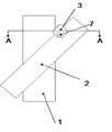
The stereogram of Fig. 1 during for the parallel axes of the axis of main rectangular waveguide among the present invention and secondary rectangular waveguide.
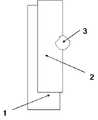
Fig. 2 is the structural perspective of coupling aperture.
Fig. 3 for improve back hollow tube coupling be attached to main rectangular waveguide sidewall or and the transmission curve of coupled end and isolation end during secondary rectangular waveguide sidewall.
Fig. 4 is the vertical view of the embodiment of the invention one.
Fig. 5 is A in the embodiment of the invention one-A profile.
Fig. 6 is the vertical view of the embodiment of the invention two.
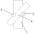
Fig. 7 is the vertical view of the embodiment of the invention three.
Fig. 8 is the vertical view of the embodiment of the invention four.
Label among the figure is expressed as respectively: 1, main rectangular waveguide; 2, secondary rectangular waveguide; 3, coupling aperture; 31, coupling cavity; 32, hollow tube coupling; 7, cylindrical metal body; 4, curved waveguide; 5, rectangular waveguide.
Embodiment
Below in conjunction with embodiment the present invention is done to specify further, but embodiment of the present invention is not limited thereto.
Like Fig. 1, shown in 2, the rectangular waveguide directional coupler comprises as the mainrectangular waveguide 1 of microwave main channel with as the secondaryrectangular waveguide 2 of sampled signal passage and as thecoupling aperture 3 of coupling channel; The main mould H face of the main mould H face of mainrectangular waveguide 1 and secondaryrectangular waveguide 2 is parallel to each other, and mainrectangular waveguide 1 is isolated with secondaryrectangular waveguide 2 each other; Mainrectangular waveguide 1 is communicated with secondaryrectangular waveguide 2 through 1 or 2coupling apertures 3; At least 1coupling aperture 3 comprise be attached to mainrectangular waveguide 1 sidewall or and the hollow tube coupling 32 of secondaryrectangular waveguide 2 sidewalls; Hollow tube coupling 32 is connected with the coupling cavity 31 of three end openings near the sidewall ofrectangular waveguide 1; Coupling cavity 31 and 32 conductings of hollow tube coupling, coupling cavity 31 between mainrectangular waveguide 1 and secondaryrectangular waveguide 2 and with mainrectangular waveguide 1 and secondaryrectangular waveguide 2 conductings.Wherein coupling aperture 3 is circle in its projection of shape of overlooking direction, and the axis of the axis of mainrectangular waveguide 1 and secondaryrectangular waveguide 2 is parallel to each other.
Concrete experimental data is as shown in Figure 3, and the experimental data of the experimental data of gained Fig. 3 for generating according to the design of Fig. 1 among the present invention compared with existing single-hole directional coupler, and except that the position difference of coupling aperture, all the other conditions are unanimity all; Fig. 3 for improve back hollow tube coupling be attached to main rectangular waveguide sidewall or and the transmission curve of coupled end and isolation end during secondary rectangular waveguide sidewall, the port S3.1 among Fig. 3 is a coupled end, port S4.1 is an isolation end.According to formula ; Wherein I is an isolation; C is the degree of coupling; D is the directivity index, and the good directionality that we can calculate this rectangular waveguide single-hole directional coupler in frequency is 6.5GHz ~ 10 GHz scopes is in-19dB.And improve when not having the hollow tube coupling, the directivity that we calculate this rectangular waveguide single-hole directional coupler in frequency is 6.5GHz ~ 10 GHz scopes is worse than-14dB.

Compare before improving with after improving; Be from the difference of experiment condition: the hollow tube coupling that improves the present invention of back is attached to main rectangular waveguide sidewall and secondary rectangular waveguide sidewall; And only have coupling aperture before improving; Its coupling aperture is very close to each other between main rectangular waveguide and the secondary rectangular waveguide between main rectangular waveguide Huo and secondary rectangular waveguide; All the other conditions are all consistent.
From on can find out that the present invention designs the design before coupler obviously is superior to improving on directional performance.
Its improvement of single-hole directional coupler compared in the past is: traditional coupling aperture is improved to the coupling channel of being made up of coupling cavity 31 and hollow tube coupling 32; Wherein coupling cavity 31 is arranged between mainrectangular waveguide 1 and the secondaryrectangular waveguide 2 it, hollow tube coupling 32 be attached to mainrectangular waveguide 1 sidewall or and secondaryrectangular waveguide 2 sidewalls; Can increase its directivity like this.
Embodiment one
Like Fig. 4, shown in 5, present embodiment comprises and is provided with mainrectangular waveguide 1 and secondaryrectangular waveguide 2, and mainrectangular waveguide 1 is the microwave main channel, and secondaryrectangular waveguide 2 is the sampled signal passage; The main mould H face of mainrectangular waveguide 1 and secondaryrectangular waveguide 2 is parallel to each other; Mainrectangular waveguide 1 is isolated with secondaryrectangular waveguide 2 each other; Have 1coupling aperture 3 to comprise to be attached to mainrectangular waveguide 1 sidewall or and the hollow tube coupling 32 of secondaryrectangular waveguide 2 sidewalls; Hollow tube coupling 32 is connected with the coupling cavity 31 of three end openings near the sidewall ofrectangular waveguide 1; Coupling cavity 31 and 32 conductings of hollow tube coupling, coupling cavity 31 between mainrectangular waveguide 1 and secondaryrectangular waveguide 2 and with mainrectangular waveguide 1 and secondaryrectangular waveguide 2 conductings.Add another axiscylindrical metal body 7 vertical in thecoupling aperture 3 with the H face of mainrectangular waveguide 1, the cross section of thiscylindrical metal body 7 be shaped as rectangle, can obtain the better directional coupler of directivity.
Embodiment two
As shown in Figure 6, be to be parallel between mainrectangular waveguide 1 and the secondaryrectangular waveguide 2 with embodiment one different place, there is notangle.Coupling aperture 3 all has only part in mainrectangular waveguide 1 and secondaryrectangular waveguide 2 the insides, and some outside.Cylindrical metal body 7 is not set in thecoupling aperture 3.
Embodiment three
As shown in Figure 7; With embodiment one different place is to be communicated with through twocoupling apertures 3 between mainrectangular waveguide 1 and the secondaryrectangular waveguide 2, and the center of twocoupling apertures 3 lays respectively at mainrectangular waveguide 1 and secondaryrectangular waveguide 2 intersects near two relative summits of the parallelogram that constitutes.
Embodiment four
As shown in Figure 8; With embodiment three different places is that mainrectangular waveguide 1 passes through 3 connections of a coupling aperture with 2 of secondary rectangular waveguides; The transition ofcurved waveguide 4 is arranged at the two ends of mainrectangular waveguide 1; Can obtain better, the wideer guide directional coupler of bandwidth of directivity like this, connectrectangular waveguide 5 at the other end ofcurved waveguide 4.
Just can realize the present invention preferably as stated.
Claims (8)
1. rectangular waveguide directional coupler is characterized in that: comprise as the main rectangular waveguide (1) of microwave main channel with as the secondary rectangular waveguide (2) of sampled signal passage and as the coupling aperture (3) of coupling channel; Said main rectangular waveguide (1) and secondary rectangular waveguide (2) are the rectangular regular metal waveguide in cross section and process; The main mould H face of the main mould H face of main rectangular waveguide (1) and secondary rectangular waveguide (2) is parallel to each other, and main rectangular waveguide (1) and secondary rectangular waveguide (2) are isolated each other; Main rectangular waveguide (1) is communicated with secondary rectangular waveguide (2) through 1 or 2 coupling apertures (3); At least 1 coupling aperture (3) comprise be attached to main rectangular waveguide (1) sidewall or and the hollow tube coupling (32) of secondary rectangular waveguide (2) sidewall; Hollow tube coupling (32) is connected with the coupling cavity (31) of three end openings near the sidewall of rectangular waveguide (1); Coupling cavity (31) and hollow tube coupling (32) conducting, coupling cavity (31) be positioned between main rectangular waveguide (1) and the secondary rectangular waveguide (2) and with main rectangular waveguide (1) and secondary rectangular waveguide (2) conducting.
2. rectangular waveguide directional coupler according to claim 1 is characterized in that: coupling aperture (3) is circle or polygon in its projection of shape of overlooking direction.
3. rectangular waveguide directional coupler according to claim 1 is characterized in that: be provided with the axis cylindrical metal body (7) vertical with the H face of main rectangular waveguide (1) in the said coupling aperture (3).
4. rectangular waveguide directional coupler according to claim 3 is characterized in that: the cross section of this cylindrical metal body (7) be shaped as polygon.
5. rectangular waveguide directional coupler according to claim 1 is characterized in that: the angle between the axis of the axis of said main rectangular waveguide (1) and secondary rectangular waveguide (2) is between 5 ° to 175 °.
6. rectangular waveguide directional coupler according to claim 1; It is characterized in that: the number of said coupling aperture (3) is 2 o'clock, and the center of two coupling apertures (3) lays respectively at main rectangular waveguide (1) and secondary rectangular waveguide (2) intersects near two relative summits of the parallelogram that constitutes after overlooking direction projection.
7. according to any described rectangular waveguide directional coupler among the claim 1-6, it is characterized in that: the one or both ends of said main rectangular waveguide (1) also are connected with curved waveguide (4).
8. according to any described rectangular waveguide directional coupler among the claim 1-6, it is characterized in that: said main rectangular waveguide (1) Huo and secondary rectangular waveguide (2) are connected with the matching structure with extraneous device matching in its one or both ends.
Priority Applications (1)
| Application Number | Priority Date | Filing Date | Title |
|---|---|---|---|
| CN2012102826182ACN102780058A (en) | 2012-08-10 | 2012-08-10 | Rectangular waveguide directional coupler |
Applications Claiming Priority (1)
| Application Number | Priority Date | Filing Date | Title |
|---|---|---|---|
| CN2012102826182ACN102780058A (en) | 2012-08-10 | 2012-08-10 | Rectangular waveguide directional coupler |
Publications (1)
| Publication Number | Publication Date |
|---|---|
| CN102780058Atrue CN102780058A (en) | 2012-11-14 |
Family
ID=47124886
Family Applications (1)
| Application Number | Title | Priority Date | Filing Date |
|---|---|---|---|
| CN2012102826182APendingCN102780058A (en) | 2012-08-10 | 2012-08-10 | Rectangular waveguide directional coupler |
Country Status (1)
| Country | Link |
|---|---|
| CN (1) | CN102780058A (en) |
Cited By (88)
| Publication number | Priority date | Publication date | Assignee | Title |
|---|---|---|---|---|
| CN103022603A (en)* | 2013-01-14 | 2013-04-03 | 成都赛纳赛德科技有限公司 | Single-hole compact directional filter with waveguides |
| CN106450618A (en)* | 2016-12-08 | 2017-02-22 | 江苏贝孚德通讯科技股份有限公司 | Filter port coupling structure and waveguide duplexer common port coupling structure |
| US9674711B2 (en) | 2013-11-06 | 2017-06-06 | At&T Intellectual Property I, L.P. | Surface-wave communications and methods thereof |
| US9699785B2 (en) | 2012-12-05 | 2017-07-04 | At&T Intellectual Property I, L.P. | Backhaul link for distributed antenna system |
| US9705610B2 (en) | 2014-10-21 | 2017-07-11 | At&T Intellectual Property I, L.P. | Transmission device with impairment compensation and methods for use therewith |
| US9742521B2 (en) | 2014-11-20 | 2017-08-22 | At&T Intellectual Property I, L.P. | Transmission device with mode division multiplexing and methods for use therewith |
| US9748626B2 (en) | 2015-05-14 | 2017-08-29 | At&T Intellectual Property I, L.P. | Plurality of cables having different cross-sectional shapes which are bundled together to form a transmission medium |
| US9793954B2 (en) | 2015-04-28 | 2017-10-17 | At&T Intellectual Property I, L.P. | Magnetic coupling device and methods for use therewith |
| US9793951B2 (en) | 2015-07-15 | 2017-10-17 | At&T Intellectual Property I, L.P. | Method and apparatus for launching a wave mode that mitigates interference |
| US9838896B1 (en) | 2016-12-09 | 2017-12-05 | At&T Intellectual Property I, L.P. | Method and apparatus for assessing network coverage |
| US9860075B1 (en) | 2016-08-26 | 2018-01-02 | At&T Intellectual Property I, L.P. | Method and communication node for broadband distribution |
| US9865911B2 (en) | 2015-06-25 | 2018-01-09 | At&T Intellectual Property I, L.P. | Waveguide system for slot radiating first electromagnetic waves that are combined into a non-fundamental wave mode second electromagnetic wave on a transmission medium |
| US9871558B2 (en) | 2014-10-21 | 2018-01-16 | At&T Intellectual Property I, L.P. | Guided-wave transmission device and methods for use therewith |
| US9876605B1 (en) | 2016-10-21 | 2018-01-23 | At&T Intellectual Property I, L.P. | Launcher and coupling system to support desired guided wave mode |
| US9876584B2 (en) | 2013-12-10 | 2018-01-23 | At&T Intellectual Property I, L.P. | Quasi-optical coupler |
| US9882657B2 (en) | 2015-06-25 | 2018-01-30 | At&T Intellectual Property I, L.P. | Methods and apparatus for inducing a fundamental wave mode on a transmission medium |
| US9893795B1 (en) | 2016-12-07 | 2018-02-13 | At&T Intellectual Property I, Lp | Method and repeater for broadband distribution |
| US9911020B1 (en) | 2016-12-08 | 2018-03-06 | At&T Intellectual Property I, L.P. | Method and apparatus for tracking via a radio frequency identification device |
| US9927517B1 (en) | 2016-12-06 | 2018-03-27 | At&T Intellectual Property I, L.P. | Apparatus and methods for sensing rainfall |
| US9948354B2 (en) | 2015-04-28 | 2018-04-17 | At&T Intellectual Property I, L.P. | Magnetic coupling device with reflective plate and methods for use therewith |
| US9948355B2 (en) | 2014-10-21 | 2018-04-17 | At&T Intellectual Property I, L.P. | Apparatus for providing communication services and methods thereof |
| US9954287B2 (en) | 2014-11-20 | 2018-04-24 | At&T Intellectual Property I, L.P. | Apparatus for converting wireless signals and electromagnetic waves and methods thereof |
| US9973416B2 (en) | 2014-10-02 | 2018-05-15 | At&T Intellectual Property I, L.P. | Method and apparatus that provides fault tolerance in a communication network |
| US9973940B1 (en) | 2017-02-27 | 2018-05-15 | At&T Intellectual Property I, L.P. | Apparatus and methods for dynamic impedance matching of a guided wave launcher |
| US9991580B2 (en) | 2016-10-21 | 2018-06-05 | At&T Intellectual Property I, L.P. | Launcher and coupling system for guided wave mode cancellation |
| US9998870B1 (en) | 2016-12-08 | 2018-06-12 | At&T Intellectual Property I, L.P. | Method and apparatus for proximity sensing |
| US10009901B2 (en) | 2015-09-16 | 2018-06-26 | At&T Intellectual Property I, L.P. | Method, apparatus, and computer-readable storage medium for managing utilization of wireless resources between base stations |
| US10009065B2 (en) | 2012-12-05 | 2018-06-26 | At&T Intellectual Property I, L.P. | Backhaul link for distributed antenna system |
| US10020844B2 (en) | 2016-12-06 | 2018-07-10 | T&T Intellectual Property I, L.P. | Method and apparatus for broadcast communication via guided waves |
| US10027397B2 (en) | 2016-12-07 | 2018-07-17 | At&T Intellectual Property I, L.P. | Distributed antenna system and methods for use therewith |
| US10033108B2 (en) | 2015-07-14 | 2018-07-24 | At&T Intellectual Property I, L.P. | Apparatus and methods for generating an electromagnetic wave having a wave mode that mitigates interference |
| US10051629B2 (en) | 2015-09-16 | 2018-08-14 | At&T Intellectual Property I, L.P. | Method and apparatus for use with a radio distributed antenna system having an in-band reference signal |
| US10051630B2 (en) | 2013-05-31 | 2018-08-14 | At&T Intellectual Property I, L.P. | Remote distributed antenna system |
| US10069185B2 (en) | 2015-06-25 | 2018-09-04 | At&T Intellectual Property I, L.P. | Methods and apparatus for inducing a non-fundamental wave mode on a transmission medium |
| US10069535B2 (en) | 2016-12-08 | 2018-09-04 | At&T Intellectual Property I, L.P. | Apparatus and methods for launching electromagnetic waves having a certain electric field structure |
| US10090594B2 (en) | 2016-11-23 | 2018-10-02 | At&T Intellectual Property I, L.P. | Antenna system having structural configurations for assembly |
| US10103422B2 (en) | 2016-12-08 | 2018-10-16 | At&T Intellectual Property I, L.P. | Method and apparatus for mounting network devices |
| US10135145B2 (en) | 2016-12-06 | 2018-11-20 | At&T Intellectual Property I, L.P. | Apparatus and methods for generating an electromagnetic wave along a transmission medium |
| US10135147B2 (en) | 2016-10-18 | 2018-11-20 | At&T Intellectual Property I, L.P. | Apparatus and methods for launching guided waves via an antenna |
| US10135146B2 (en) | 2016-10-18 | 2018-11-20 | At&T Intellectual Property I, L.P. | Apparatus and methods for launching guided waves via circuits |
| US10139820B2 (en) | 2016-12-07 | 2018-11-27 | At&T Intellectual Property I, L.P. | Method and apparatus for deploying equipment of a communication system |
| US10148016B2 (en) | 2015-07-14 | 2018-12-04 | At&T Intellectual Property I, L.P. | Apparatus and methods for communicating utilizing an antenna array |
| US10168695B2 (en) | 2016-12-07 | 2019-01-01 | At&T Intellectual Property I, L.P. | Method and apparatus for controlling an unmanned aircraft |
| US10178445B2 (en) | 2016-11-23 | 2019-01-08 | At&T Intellectual Property I, L.P. | Methods, devices, and systems for load balancing between a plurality of waveguides |
| US10205655B2 (en) | 2015-07-14 | 2019-02-12 | At&T Intellectual Property I, L.P. | Apparatus and methods for communicating utilizing an antenna array and multiple communication paths |
| US10224634B2 (en) | 2016-11-03 | 2019-03-05 | At&T Intellectual Property I, L.P. | Methods and apparatus for adjusting an operational characteristic of an antenna |
| US10243270B2 (en) | 2016-12-07 | 2019-03-26 | At&T Intellectual Property I, L.P. | Beam adaptive multi-feed dielectric antenna system and methods for use therewith |
| US10264586B2 (en) | 2016-12-09 | 2019-04-16 | At&T Mobility Ii Llc | Cloud-based packet controller and methods for use therewith |
| US10291334B2 (en) | 2016-11-03 | 2019-05-14 | At&T Intellectual Property I, L.P. | System for detecting a fault in a communication system |
| US10298293B2 (en) | 2017-03-13 | 2019-05-21 | At&T Intellectual Property I, L.P. | Apparatus of communication utilizing wireless network devices |
| US10305190B2 (en) | 2016-12-01 | 2019-05-28 | At&T Intellectual Property I, L.P. | Reflecting dielectric antenna system and methods for use therewith |
| US10312567B2 (en) | 2016-10-26 | 2019-06-04 | At&T Intellectual Property I, L.P. | Launcher with planar strip antenna and methods for use therewith |
| US10320586B2 (en) | 2015-07-14 | 2019-06-11 | At&T Intellectual Property I, L.P. | Apparatus and methods for generating non-interfering electromagnetic waves on an insulated transmission medium |
| US10326494B2 (en) | 2016-12-06 | 2019-06-18 | At&T Intellectual Property I, L.P. | Apparatus for measurement de-embedding and methods for use therewith |
| US10326689B2 (en) | 2016-12-08 | 2019-06-18 | At&T Intellectual Property I, L.P. | Method and system for providing alternative communication paths |
| US10340603B2 (en) | 2016-11-23 | 2019-07-02 | At&T Intellectual Property I, L.P. | Antenna system having shielded structural configurations for assembly |
| US10340601B2 (en) | 2016-11-23 | 2019-07-02 | At&T Intellectual Property I, L.P. | Multi-antenna system and methods for use therewith |
| US10341142B2 (en) | 2015-07-14 | 2019-07-02 | At&T Intellectual Property I, L.P. | Apparatus and methods for generating non-interfering electromagnetic waves on an uninsulated conductor |
| US10340573B2 (en) | 2016-10-26 | 2019-07-02 | At&T Intellectual Property I, L.P. | Launcher with cylindrical coupling device and methods for use therewith |
| US10340600B2 (en) | 2016-10-18 | 2019-07-02 | At&T Intellectual Property I, L.P. | Apparatus and methods for launching guided waves via plural waveguide systems |
| US10340983B2 (en) | 2016-12-09 | 2019-07-02 | At&T Intellectual Property I, L.P. | Method and apparatus for surveying remote sites via guided wave communications |
| US10359749B2 (en) | 2016-12-07 | 2019-07-23 | At&T Intellectual Property I, L.P. | Method and apparatus for utilities management via guided wave communication |
| US10361489B2 (en) | 2016-12-01 | 2019-07-23 | At&T Intellectual Property I, L.P. | Dielectric dish antenna system and methods for use therewith |
| US10374316B2 (en) | 2016-10-21 | 2019-08-06 | At&T Intellectual Property I, L.P. | System and dielectric antenna with non-uniform dielectric |
| US10382976B2 (en) | 2016-12-06 | 2019-08-13 | At&T Intellectual Property I, L.P. | Method and apparatus for managing wireless communications based on communication paths and network device positions |
| US10389037B2 (en) | 2016-12-08 | 2019-08-20 | At&T Intellectual Property I, L.P. | Apparatus and methods for selecting sections of an antenna array and use therewith |
| US10389029B2 (en) | 2016-12-07 | 2019-08-20 | At&T Intellectual Property I, L.P. | Multi-feed dielectric antenna system with core selection and methods for use therewith |
| US10411356B2 (en) | 2016-12-08 | 2019-09-10 | At&T Intellectual Property I, L.P. | Apparatus and methods for selectively targeting communication devices with an antenna array |
| US10439675B2 (en) | 2016-12-06 | 2019-10-08 | At&T Intellectual Property I, L.P. | Method and apparatus for repeating guided wave communication signals |
| US10446936B2 (en) | 2016-12-07 | 2019-10-15 | At&T Intellectual Property I, L.P. | Multi-feed dielectric antenna system and methods for use therewith |
| US10498044B2 (en) | 2016-11-03 | 2019-12-03 | At&T Intellectual Property I, L.P. | Apparatus for configuring a surface of an antenna |
| US10530505B2 (en) | 2016-12-08 | 2020-01-07 | At&T Intellectual Property I, L.P. | Apparatus and methods for launching electromagnetic waves along a transmission medium |
| US10535928B2 (en) | 2016-11-23 | 2020-01-14 | At&T Intellectual Property I, L.P. | Antenna system and methods for use therewith |
| US10547348B2 (en) | 2016-12-07 | 2020-01-28 | At&T Intellectual Property I, L.P. | Method and apparatus for switching transmission mediums in a communication system |
| US10601494B2 (en) | 2016-12-08 | 2020-03-24 | At&T Intellectual Property I, L.P. | Dual-band communication device and method for use therewith |
| US10637149B2 (en) | 2016-12-06 | 2020-04-28 | At&T Intellectual Property I, L.P. | Injection molded dielectric antenna and methods for use therewith |
| US10694379B2 (en) | 2016-12-06 | 2020-06-23 | At&T Intellectual Property I, L.P. | Waveguide system with device-based authentication and methods for use therewith |
| US10727599B2 (en) | 2016-12-06 | 2020-07-28 | At&T Intellectual Property I, L.P. | Launcher with slot antenna and methods for use therewith |
| US10755542B2 (en) | 2016-12-06 | 2020-08-25 | At&T Intellectual Property I, L.P. | Method and apparatus for surveillance via guided wave communication |
| US10777873B2 (en) | 2016-12-08 | 2020-09-15 | At&T Intellectual Property I, L.P. | Method and apparatus for mounting network devices |
| US10811767B2 (en) | 2016-10-21 | 2020-10-20 | At&T Intellectual Property I, L.P. | System and dielectric antenna with convex dielectric radome |
| US10812174B2 (en) | 2015-06-03 | 2020-10-20 | At&T Intellectual Property I, L.P. | Client node device and methods for use therewith |
| US10819035B2 (en) | 2016-12-06 | 2020-10-27 | At&T Intellectual Property I, L.P. | Launcher with helical antenna and methods for use therewith |
| US10916969B2 (en) | 2016-12-08 | 2021-02-09 | At&T Intellectual Property I, L.P. | Method and apparatus for providing power using an inductive coupling |
| US10938108B2 (en) | 2016-12-08 | 2021-03-02 | At&T Intellectual Property I, L.P. | Frequency selective multi-feed dielectric antenna system and methods for use therewith |
| US11032819B2 (en) | 2016-09-15 | 2021-06-08 | At&T Intellectual Property I, L.P. | Method and apparatus for use with a radio distributed antenna system having a control channel reference signal |
| CN113030820A (en)* | 2021-04-25 | 2021-06-25 | 国仪量子(合肥)技术有限公司 | Table type continuous wave paramagnetic resonance spectrometer probe |
| CN114079137A (en)* | 2020-08-12 | 2022-02-22 | 布鲁克碧奥斯平有限公司 | Microwave coupling device for iris aperture comprising a plurality of conductor loops |
Citations (3)
| Publication number | Priority date | Publication date | Assignee | Title |
|---|---|---|---|---|
| JPS5813001A (en)* | 1981-07-16 | 1983-01-25 | Nec Corp | Directional filter |
| DE19544260C1 (en)* | 1995-11-28 | 1997-05-07 | Bosch Gmbh Robert | Directional coupler |
| CN202678499U (en)* | 2012-08-10 | 2013-01-16 | 成都赛纳赛德科技有限公司 | Rectangular waveguide directional coupler |
- 2012
- 2012-08-10CNCN2012102826182Apatent/CN102780058A/enactivePending
Patent Citations (3)
| Publication number | Priority date | Publication date | Assignee | Title |
|---|---|---|---|---|
| JPS5813001A (en)* | 1981-07-16 | 1983-01-25 | Nec Corp | Directional filter |
| DE19544260C1 (en)* | 1995-11-28 | 1997-05-07 | Bosch Gmbh Robert | Directional coupler |
| CN202678499U (en)* | 2012-08-10 | 2013-01-16 | 成都赛纳赛德科技有限公司 | Rectangular waveguide directional coupler |
Non-Patent Citations (1)
| Title |
|---|
| 陆军: "矩形波导宽壁单孔定向耦合器的方向性", 《广西大学学报》, vol. 24, 31 December 1999 (1999-12-31)* |
Cited By (102)
| Publication number | Priority date | Publication date | Assignee | Title |
|---|---|---|---|---|
| US9788326B2 (en) | 2012-12-05 | 2017-10-10 | At&T Intellectual Property I, L.P. | Backhaul link for distributed antenna system |
| US10194437B2 (en) | 2012-12-05 | 2019-01-29 | At&T Intellectual Property I, L.P. | Backhaul link for distributed antenna system |
| US9699785B2 (en) | 2012-12-05 | 2017-07-04 | At&T Intellectual Property I, L.P. | Backhaul link for distributed antenna system |
| US10009065B2 (en) | 2012-12-05 | 2018-06-26 | At&T Intellectual Property I, L.P. | Backhaul link for distributed antenna system |
| CN103022603B (en)* | 2013-01-14 | 2015-07-29 | 成都赛纳赛德科技有限公司 | Single hole compact waveguide directional filter |
| CN103022603A (en)* | 2013-01-14 | 2013-04-03 | 成都赛纳赛德科技有限公司 | Single-hole compact directional filter with waveguides |
| US10051630B2 (en) | 2013-05-31 | 2018-08-14 | At&T Intellectual Property I, L.P. | Remote distributed antenna system |
| US9674711B2 (en) | 2013-11-06 | 2017-06-06 | At&T Intellectual Property I, L.P. | Surface-wave communications and methods thereof |
| US9876584B2 (en) | 2013-12-10 | 2018-01-23 | At&T Intellectual Property I, L.P. | Quasi-optical coupler |
| US9973416B2 (en) | 2014-10-02 | 2018-05-15 | At&T Intellectual Property I, L.P. | Method and apparatus that provides fault tolerance in a communication network |
| US9948355B2 (en) | 2014-10-21 | 2018-04-17 | At&T Intellectual Property I, L.P. | Apparatus for providing communication services and methods thereof |
| US9960808B2 (en) | 2014-10-21 | 2018-05-01 | At&T Intellectual Property I, L.P. | Guided-wave transmission device and methods for use therewith |
| US9876587B2 (en) | 2014-10-21 | 2018-01-23 | At&T Intellectual Property I, L.P. | Transmission device with impairment compensation and methods for use therewith |
| US9705610B2 (en) | 2014-10-21 | 2017-07-11 | At&T Intellectual Property I, L.P. | Transmission device with impairment compensation and methods for use therewith |
| US9871558B2 (en) | 2014-10-21 | 2018-01-16 | At&T Intellectual Property I, L.P. | Guided-wave transmission device and methods for use therewith |
| US9742521B2 (en) | 2014-11-20 | 2017-08-22 | At&T Intellectual Property I, L.P. | Transmission device with mode division multiplexing and methods for use therewith |
| US9749083B2 (en) | 2014-11-20 | 2017-08-29 | At&T Intellectual Property I, L.P. | Transmission device with mode division multiplexing and methods for use therewith |
| US9954287B2 (en) | 2014-11-20 | 2018-04-24 | At&T Intellectual Property I, L.P. | Apparatus for converting wireless signals and electromagnetic waves and methods thereof |
| US10069537B2 (en) | 2015-04-28 | 2018-09-04 | At&T Intellectual Property I, L.P. | Magnetic coupling device and methods for use therewith |
| US10193596B2 (en) | 2015-04-28 | 2019-01-29 | At&T Intellectual Property I, L.P. | Magnetic coupling device with reflective plate and methods for use therewith |
| US9793954B2 (en) | 2015-04-28 | 2017-10-17 | At&T Intellectual Property I, L.P. | Magnetic coupling device and methods for use therewith |
| US10432259B2 (en) | 2015-04-28 | 2019-10-01 | At&T Intellectual Property I, L.P. | Magnetic coupling device and methods for use therewith |
| US10630343B2 (en) | 2015-04-28 | 2020-04-21 | At&T Intellectual Property I, L.P. | Magnetic coupling device and methods for use therewith |
| US10476551B2 (en) | 2015-04-28 | 2019-11-12 | At&T Intellectual Property I, L.P. | Magnetic coupling device with reflective plate and methods for use therewith |
| US9948354B2 (en) | 2015-04-28 | 2018-04-17 | At&T Intellectual Property I, L.P. | Magnetic coupling device with reflective plate and methods for use therewith |
| US9748626B2 (en) | 2015-05-14 | 2017-08-29 | At&T Intellectual Property I, L.P. | Plurality of cables having different cross-sectional shapes which are bundled together to form a transmission medium |
| US10812174B2 (en) | 2015-06-03 | 2020-10-20 | At&T Intellectual Property I, L.P. | Client node device and methods for use therewith |
| US9865911B2 (en) | 2015-06-25 | 2018-01-09 | At&T Intellectual Property I, L.P. | Waveguide system for slot radiating first electromagnetic waves that are combined into a non-fundamental wave mode second electromagnetic wave on a transmission medium |
| US9882657B2 (en) | 2015-06-25 | 2018-01-30 | At&T Intellectual Property I, L.P. | Methods and apparatus for inducing a fundamental wave mode on a transmission medium |
| US10069185B2 (en) | 2015-06-25 | 2018-09-04 | At&T Intellectual Property I, L.P. | Methods and apparatus for inducing a non-fundamental wave mode on a transmission medium |
| US10090601B2 (en) | 2015-06-25 | 2018-10-02 | At&T Intellectual Property I, L.P. | Waveguide system and methods for inducing a non-fundamental wave mode on a transmission medium |
| US10320586B2 (en) | 2015-07-14 | 2019-06-11 | At&T Intellectual Property I, L.P. | Apparatus and methods for generating non-interfering electromagnetic waves on an insulated transmission medium |
| US10148016B2 (en) | 2015-07-14 | 2018-12-04 | At&T Intellectual Property I, L.P. | Apparatus and methods for communicating utilizing an antenna array |
| US10033108B2 (en) | 2015-07-14 | 2018-07-24 | At&T Intellectual Property I, L.P. | Apparatus and methods for generating an electromagnetic wave having a wave mode that mitigates interference |
| US10341142B2 (en) | 2015-07-14 | 2019-07-02 | At&T Intellectual Property I, L.P. | Apparatus and methods for generating non-interfering electromagnetic waves on an uninsulated conductor |
| US10205655B2 (en) | 2015-07-14 | 2019-02-12 | At&T Intellectual Property I, L.P. | Apparatus and methods for communicating utilizing an antenna array and multiple communication paths |
| US9793951B2 (en) | 2015-07-15 | 2017-10-17 | At&T Intellectual Property I, L.P. | Method and apparatus for launching a wave mode that mitigates interference |
| US10009901B2 (en) | 2015-09-16 | 2018-06-26 | At&T Intellectual Property I, L.P. | Method, apparatus, and computer-readable storage medium for managing utilization of wireless resources between base stations |
| US10051629B2 (en) | 2015-09-16 | 2018-08-14 | At&T Intellectual Property I, L.P. | Method and apparatus for use with a radio distributed antenna system having an in-band reference signal |
| US9860075B1 (en) | 2016-08-26 | 2018-01-02 | At&T Intellectual Property I, L.P. | Method and communication node for broadband distribution |
| US11032819B2 (en) | 2016-09-15 | 2021-06-08 | At&T Intellectual Property I, L.P. | Method and apparatus for use with a radio distributed antenna system having a control channel reference signal |
| US10340600B2 (en) | 2016-10-18 | 2019-07-02 | At&T Intellectual Property I, L.P. | Apparatus and methods for launching guided waves via plural waveguide systems |
| US10135147B2 (en) | 2016-10-18 | 2018-11-20 | At&T Intellectual Property I, L.P. | Apparatus and methods for launching guided waves via an antenna |
| US10135146B2 (en) | 2016-10-18 | 2018-11-20 | At&T Intellectual Property I, L.P. | Apparatus and methods for launching guided waves via circuits |
| US9876605B1 (en) | 2016-10-21 | 2018-01-23 | At&T Intellectual Property I, L.P. | Launcher and coupling system to support desired guided wave mode |
| US10374316B2 (en) | 2016-10-21 | 2019-08-06 | At&T Intellectual Property I, L.P. | System and dielectric antenna with non-uniform dielectric |
| US10811767B2 (en) | 2016-10-21 | 2020-10-20 | At&T Intellectual Property I, L.P. | System and dielectric antenna with convex dielectric radome |
| US9991580B2 (en) | 2016-10-21 | 2018-06-05 | At&T Intellectual Property I, L.P. | Launcher and coupling system for guided wave mode cancellation |
| US10340573B2 (en) | 2016-10-26 | 2019-07-02 | At&T Intellectual Property I, L.P. | Launcher with cylindrical coupling device and methods for use therewith |
| US10312567B2 (en) | 2016-10-26 | 2019-06-04 | At&T Intellectual Property I, L.P. | Launcher with planar strip antenna and methods for use therewith |
| US10291334B2 (en) | 2016-11-03 | 2019-05-14 | At&T Intellectual Property I, L.P. | System for detecting a fault in a communication system |
| US10498044B2 (en) | 2016-11-03 | 2019-12-03 | At&T Intellectual Property I, L.P. | Apparatus for configuring a surface of an antenna |
| US10224634B2 (en) | 2016-11-03 | 2019-03-05 | At&T Intellectual Property I, L.P. | Methods and apparatus for adjusting an operational characteristic of an antenna |
| US10178445B2 (en) | 2016-11-23 | 2019-01-08 | At&T Intellectual Property I, L.P. | Methods, devices, and systems for load balancing between a plurality of waveguides |
| US10340603B2 (en) | 2016-11-23 | 2019-07-02 | At&T Intellectual Property I, L.P. | Antenna system having shielded structural configurations for assembly |
| US10535928B2 (en) | 2016-11-23 | 2020-01-14 | At&T Intellectual Property I, L.P. | Antenna system and methods for use therewith |
| US10090594B2 (en) | 2016-11-23 | 2018-10-02 | At&T Intellectual Property I, L.P. | Antenna system having structural configurations for assembly |
| US10340601B2 (en) | 2016-11-23 | 2019-07-02 | At&T Intellectual Property I, L.P. | Multi-antenna system and methods for use therewith |
| US10361489B2 (en) | 2016-12-01 | 2019-07-23 | At&T Intellectual Property I, L.P. | Dielectric dish antenna system and methods for use therewith |
| US10305190B2 (en) | 2016-12-01 | 2019-05-28 | At&T Intellectual Property I, L.P. | Reflecting dielectric antenna system and methods for use therewith |
| US10439675B2 (en) | 2016-12-06 | 2019-10-08 | At&T Intellectual Property I, L.P. | Method and apparatus for repeating guided wave communication signals |
| US10382976B2 (en) | 2016-12-06 | 2019-08-13 | At&T Intellectual Property I, L.P. | Method and apparatus for managing wireless communications based on communication paths and network device positions |
| US10326494B2 (en) | 2016-12-06 | 2019-06-18 | At&T Intellectual Property I, L.P. | Apparatus for measurement de-embedding and methods for use therewith |
| US10819035B2 (en) | 2016-12-06 | 2020-10-27 | At&T Intellectual Property I, L.P. | Launcher with helical antenna and methods for use therewith |
| US10135145B2 (en) | 2016-12-06 | 2018-11-20 | At&T Intellectual Property I, L.P. | Apparatus and methods for generating an electromagnetic wave along a transmission medium |
| US10637149B2 (en) | 2016-12-06 | 2020-04-28 | At&T Intellectual Property I, L.P. | Injection molded dielectric antenna and methods for use therewith |
| US9927517B1 (en) | 2016-12-06 | 2018-03-27 | At&T Intellectual Property I, L.P. | Apparatus and methods for sensing rainfall |
| US10755542B2 (en) | 2016-12-06 | 2020-08-25 | At&T Intellectual Property I, L.P. | Method and apparatus for surveillance via guided wave communication |
| US10020844B2 (en) | 2016-12-06 | 2018-07-10 | T&T Intellectual Property I, L.P. | Method and apparatus for broadcast communication via guided waves |
| US10727599B2 (en) | 2016-12-06 | 2020-07-28 | At&T Intellectual Property I, L.P. | Launcher with slot antenna and methods for use therewith |
| US10694379B2 (en) | 2016-12-06 | 2020-06-23 | At&T Intellectual Property I, L.P. | Waveguide system with device-based authentication and methods for use therewith |
| US10359749B2 (en) | 2016-12-07 | 2019-07-23 | At&T Intellectual Property I, L.P. | Method and apparatus for utilities management via guided wave communication |
| US10027397B2 (en) | 2016-12-07 | 2018-07-17 | At&T Intellectual Property I, L.P. | Distributed antenna system and methods for use therewith |
| US10139820B2 (en) | 2016-12-07 | 2018-11-27 | At&T Intellectual Property I, L.P. | Method and apparatus for deploying equipment of a communication system |
| US9893795B1 (en) | 2016-12-07 | 2018-02-13 | At&T Intellectual Property I, Lp | Method and repeater for broadband distribution |
| US10389029B2 (en) | 2016-12-07 | 2019-08-20 | At&T Intellectual Property I, L.P. | Multi-feed dielectric antenna system with core selection and methods for use therewith |
| US10547348B2 (en) | 2016-12-07 | 2020-01-28 | At&T Intellectual Property I, L.P. | Method and apparatus for switching transmission mediums in a communication system |
| US10243270B2 (en) | 2016-12-07 | 2019-03-26 | At&T Intellectual Property I, L.P. | Beam adaptive multi-feed dielectric antenna system and methods for use therewith |
| US10168695B2 (en) | 2016-12-07 | 2019-01-01 | At&T Intellectual Property I, L.P. | Method and apparatus for controlling an unmanned aircraft |
| US10446936B2 (en) | 2016-12-07 | 2019-10-15 | At&T Intellectual Property I, L.P. | Multi-feed dielectric antenna system and methods for use therewith |
| US10777873B2 (en) | 2016-12-08 | 2020-09-15 | At&T Intellectual Property I, L.P. | Method and apparatus for mounting network devices |
| US10103422B2 (en) | 2016-12-08 | 2018-10-16 | At&T Intellectual Property I, L.P. | Method and apparatus for mounting network devices |
| US10530505B2 (en) | 2016-12-08 | 2020-01-07 | At&T Intellectual Property I, L.P. | Apparatus and methods for launching electromagnetic waves along a transmission medium |
| US9998870B1 (en) | 2016-12-08 | 2018-06-12 | At&T Intellectual Property I, L.P. | Method and apparatus for proximity sensing |
| US10411356B2 (en) | 2016-12-08 | 2019-09-10 | At&T Intellectual Property I, L.P. | Apparatus and methods for selectively targeting communication devices with an antenna array |
| US10601494B2 (en) | 2016-12-08 | 2020-03-24 | At&T Intellectual Property I, L.P. | Dual-band communication device and method for use therewith |
| US9911020B1 (en) | 2016-12-08 | 2018-03-06 | At&T Intellectual Property I, L.P. | Method and apparatus for tracking via a radio frequency identification device |
| US10389037B2 (en) | 2016-12-08 | 2019-08-20 | At&T Intellectual Property I, L.P. | Apparatus and methods for selecting sections of an antenna array and use therewith |
| CN106450618A (en)* | 2016-12-08 | 2017-02-22 | 江苏贝孚德通讯科技股份有限公司 | Filter port coupling structure and waveguide duplexer common port coupling structure |
| US10938108B2 (en) | 2016-12-08 | 2021-03-02 | At&T Intellectual Property I, L.P. | Frequency selective multi-feed dielectric antenna system and methods for use therewith |
| US10069535B2 (en) | 2016-12-08 | 2018-09-04 | At&T Intellectual Property I, L.P. | Apparatus and methods for launching electromagnetic waves having a certain electric field structure |
| US10916969B2 (en) | 2016-12-08 | 2021-02-09 | At&T Intellectual Property I, L.P. | Method and apparatus for providing power using an inductive coupling |
| US10326689B2 (en) | 2016-12-08 | 2019-06-18 | At&T Intellectual Property I, L.P. | Method and system for providing alternative communication paths |
| US9838896B1 (en) | 2016-12-09 | 2017-12-05 | At&T Intellectual Property I, L.P. | Method and apparatus for assessing network coverage |
| US10340983B2 (en) | 2016-12-09 | 2019-07-02 | At&T Intellectual Property I, L.P. | Method and apparatus for surveying remote sites via guided wave communications |
| US10264586B2 (en) | 2016-12-09 | 2019-04-16 | At&T Mobility Ii Llc | Cloud-based packet controller and methods for use therewith |
| US9973940B1 (en) | 2017-02-27 | 2018-05-15 | At&T Intellectual Property I, L.P. | Apparatus and methods for dynamic impedance matching of a guided wave launcher |
| US10298293B2 (en) | 2017-03-13 | 2019-05-21 | At&T Intellectual Property I, L.P. | Apparatus of communication utilizing wireless network devices |
| CN114079137A (en)* | 2020-08-12 | 2022-02-22 | 布鲁克碧奥斯平有限公司 | Microwave coupling device for iris aperture comprising a plurality of conductor loops |
| CN114079137B (en)* | 2020-08-12 | 2023-02-10 | 布鲁克碧奥斯平有限公司 | Microwave coupling device for iris aperture comprising a plurality of conductor loops |
| US11914010B2 (en) | 2020-08-12 | 2024-02-27 | Bruker Biospin Gmbh | Microwave coupling device for iris apertures, comprising a plurality of conductor loops |
| CN113030820A (en)* | 2021-04-25 | 2021-06-25 | 国仪量子(合肥)技术有限公司 | Table type continuous wave paramagnetic resonance spectrometer probe |
Similar Documents
| Publication | Publication Date | Title |
|---|---|---|
| CN102780058A (en) | Rectangular waveguide directional coupler | |
| CN202678499U (en) | Rectangular waveguide directional coupler | |
| CN102810710B (en) | Directional coupler with master ridge waveguide and slave ridge waveguide | |
| CN102800914B (en) | Porous ridge waveguide directional couplers with different dimensions | |
| CN102780056B (en) | Directional coupler with main and auxiliary rectangular coaxial lines | |
| CN202678489U (en) | Directional coupler with main and auxiliary ridge waveguides different in size | |
| CN202839931U (en) | Directional coupler with rectangular coaxial lines | |
| CN202749492U (en) | Micro-strip directional coupler | |
| CN202678493U (en) | Size-variable multi-hole rectangular waveguide directional coupler | |
| CN102810711B (en) | Rectangular porous waveguide directional coupler with cross distributed coupling holes | |
| CN102790255B (en) | Directional coupler with different-sized main rectangular waveguide and auxiliary rectangular waveguide | |
| CN102780057A (en) | Directional coupler with ridge waveguides | |
| CN202678498U (en) | Directional coupler with main and auxiliary rectangular waveguides different in size | |
| CN102820511A (en) | Microstrip directional coupler | |
| CN102790256B (en) | Porous directional coupler with main and assistant ridge waveguides in different sizes | |
| CN203225326U (en) | Porous directional coupler provided with main rectangular waveguide and auxiliary rectangular waveguide having different sizes | |
| CN202678495U (en) | Ridge waveguide directional coupler | |
| CN202678494U (en) | Directional coupler with main and auxiliary rectangular coaxial lines different in size | |
| CN102780060B (en) | Porous rectangular waveguide directional coupler with different size | |
| CN202695692U (en) | A multi-hole directional coupler for a rectangular waveguide with coupling holes distributed in an interlacing manner | |
| CN102810707B (en) | Porous ridge waveguide directional coupler with cross distributed coupling holes | |
| CN102881982B (en) | Rectangular coaxial line directional coupler | |
| CN202695690U (en) | A multi-hole directional coupler for a rectangular waveguide with coupling holes positioned on one side of a main rectangular waveguide | |
| CN202695691U (en) | A multi-hole directional coupler for a rectangular coaxial line with coupling holes distributed in an interlacing manner | |
| CN202678491U (en) | Multi-hole microtrip directional coupler with coupling holes distributed in staggered manner |
Legal Events
| Date | Code | Title | Description |
|---|---|---|---|
| C06 | Publication | ||
| PB01 | Publication | ||
| C10 | Entry into substantive examination | ||
| SE01 | Entry into force of request for substantive examination | ||
| C12 | Rejection of a patent application after its publication | ||
| RJ01 | Rejection of invention patent application after publication | Application publication date:20121114 |