CN102773865A - Robot hand and robot - Google Patents
Robot hand and robotDownload PDFInfo
- Publication number
- CN102773865A CN102773865ACN2012101402949ACN201210140294ACN102773865ACN 102773865 ACN102773865 ACN 102773865ACN 2012101402949 ACN2012101402949 ACN 2012101402949ACN 201210140294 ACN201210140294 ACN 201210140294ACN 102773865 ACN102773865 ACN 102773865A
- Authority
- CN
- China
- Prior art keywords
- finger
- fingers
- contact
- manipulator
- force
- Prior art date
- Legal status (The legal status is an assumption and is not a legal conclusion. Google has not performed a legal analysis and makes no representation as to the accuracy of the status listed.)
- Granted
Links
- 238000001514detection methodMethods0.000claimsabstractdescription93
- 238000006243chemical reactionMethods0.000claimsabstractdescription59
- 230000007246mechanismEffects0.000claimsdescription17
- 238000013459approachMethods0.000claimsdescription14
- 238000000034methodMethods0.000description24
- 238000010586diagramMethods0.000description10
- 230000008569processEffects0.000description9
- 230000009471actionEffects0.000description4
- 238000012545processingMethods0.000description3
- 238000012937correctionMethods0.000description2
- 238000004519manufacturing processMethods0.000description2
- 230000004048modificationEffects0.000description2
- 238000012986modificationMethods0.000description2
- 230000008859changeEffects0.000description1
- 238000005516engineering processMethods0.000description1
- 238000003541multi-stage reactionMethods0.000description1
- 238000007591painting processMethods0.000description1
- 238000003466weldingMethods0.000description1
Images


Classifications
- B—PERFORMING OPERATIONS; TRANSPORTING
- B25—HAND TOOLS; PORTABLE POWER-DRIVEN TOOLS; MANIPULATORS
- B25J—MANIPULATORS; CHAMBERS PROVIDED WITH MANIPULATION DEVICES
- B25J15/00—Gripping heads and other end effectors
- B25J15/08—Gripping heads and other end effectors having finger members
- B25J15/10—Gripping heads and other end effectors having finger members with three or more finger members
- B—PERFORMING OPERATIONS; TRANSPORTING
- B25—HAND TOOLS; PORTABLE POWER-DRIVEN TOOLS; MANIPULATORS
- B25J—MANIPULATORS; CHAMBERS PROVIDED WITH MANIPULATION DEVICES
- B25J15/00—Gripping heads and other end effectors
- B25J15/02—Gripping heads and other end effectors servo-actuated
- B25J15/0253—Gripping heads and other end effectors servo-actuated comprising parallel grippers
- B—PERFORMING OPERATIONS; TRANSPORTING
- B25—HAND TOOLS; PORTABLE POWER-DRIVEN TOOLS; MANIPULATORS
- B25J—MANIPULATORS; CHAMBERS PROVIDED WITH MANIPULATION DEVICES
- B25J9/00—Programme-controlled manipulators
- B25J9/16—Programme controls
- B25J9/1612—Programme controls characterised by the hand, wrist, grip control
- Y—GENERAL TAGGING OF NEW TECHNOLOGICAL DEVELOPMENTS; GENERAL TAGGING OF CROSS-SECTIONAL TECHNOLOGIES SPANNING OVER SEVERAL SECTIONS OF THE IPC; TECHNICAL SUBJECTS COVERED BY FORMER USPC CROSS-REFERENCE ART COLLECTIONS [XRACs] AND DIGESTS
- Y10—TECHNICAL SUBJECTS COVERED BY FORMER USPC
- Y10S—TECHNICAL SUBJECTS COVERED BY FORMER USPC CROSS-REFERENCE ART COLLECTIONS [XRACs] AND DIGESTS
- Y10S901/00—Robots
- Y10S901/30—End effector
- Y10S901/31—Gripping jaw
- Y10S901/32—Servo-actuated
- Y10S901/33—Tactile sensor
- Y—GENERAL TAGGING OF NEW TECHNOLOGICAL DEVELOPMENTS; GENERAL TAGGING OF CROSS-SECTIONAL TECHNOLOGIES SPANNING OVER SEVERAL SECTIONS OF THE IPC; TECHNICAL SUBJECTS COVERED BY FORMER USPC CROSS-REFERENCE ART COLLECTIONS [XRACs] AND DIGESTS
- Y10—TECHNICAL SUBJECTS COVERED BY FORMER USPC
- Y10S—TECHNICAL SUBJECTS COVERED BY FORMER USPC CROSS-REFERENCE ART COLLECTIONS [XRACs] AND DIGESTS
- Y10S901/00—Robots
- Y10S901/30—End effector
- Y10S901/31—Gripping jaw
- Y10S901/32—Servo-actuated
- Y10S901/34—Servo-actuated force feedback
Landscapes
- Engineering & Computer Science (AREA)
- Robotics (AREA)
- Mechanical Engineering (AREA)
- Health & Medical Sciences (AREA)
- General Health & Medical Sciences (AREA)
- Orthopedic Medicine & Surgery (AREA)
- Manipulator (AREA)
Abstract
Translated fromChinese
Description
Translated fromChinese技术领域technical field
本发明涉及使用多根手指把持对象物的机械手以及机器人。The present invention relates to a manipulator and a robot that grasp an object using a plurality of fingers.
背景技术Background technique
在制造现场的焊接、涂装工序中,广泛地使用机器人。并且,开发了具有使用多根手指把持对象物的能力的机械手,在搬运、组装各种部件等工序中,也使用机器人。Robots are widely used in welding and painting processes at manufacturing sites. In addition, manipulators capable of grasping objects with multiple fingers have been developed, and robots are also used in processes such as conveying and assembling various parts.
在此,机械手需要以适当的力把持对象物,以避免损伤想要把持的对象物。并且,从提高制造现场的生产率的观点来看,希望能够尽可能迅速地移动手指来把持对象物。Here, the manipulator needs to hold the object with an appropriate force so as not to damage the object to be held. In addition, from the viewpoint of improving productivity at a manufacturing site, it is desirable to be able to move fingers as quickly as possible to grasp an object.
因此,以同时满足此类要求作为目的,提出了如下技术(专利文献1)。首先,通过进行位置控制使机械手的手指靠近对象物正前方的目标位置。接下来,通过在使把持力不超过规定值的状态下进行位置控制(带外力限制的位置控制),来使机械手的手指与对象物接触。之后,提出了通过进行力控制而以适当的力把持对象物的技术。在该提案的技术中,在通过进行位置控制而使机械手的手指迅速地靠近对象物之后,能够通过进行力控制而以适当的力把持对象物。并且,通过进行带外力限制的位置控制,能够顺畅地进行在机械手的手指靠近对象物后、与对象物接触,且随后成为以适当的力把持对象物的状态为止这一连串的变化。Therefore, for the purpose of simultaneously satisfying such requirements, the following technology has been proposed (Patent Document 1). First, the finger of the manipulator is brought close to the target position directly in front of the object by performing position control. Next, the fingers of the manipulator are brought into contact with the object by performing position control (position control with external force limitation) in a state where the gripping force does not exceed a predetermined value. Thereafter, a technique for gripping an object with an appropriate force by performing force control has been proposed. In this proposed technique, after the fingers of the manipulator are quickly brought close to the object by performing position control, it is possible to grasp the object with an appropriate force by performing force control. In addition, by performing position control with external force limitation, a series of changes can be smoothly performed until the fingers of the manipulator approach the object, come into contact with the object, and then grasp the object with an appropriate force.
专利文献1:日本特开2009-066685号公报Patent Document 1: Japanese Patent Laid-Open No. 2009-066685
但是,在上述专利文献1所记载的技术中,需要在与对象物接触的全部手指设置接触传感器。并且,在机械手的手指与对象物接触之前的阶段,必须将控制方法从位置控制切换至带外力限制的位置控制,之后进一步切换至力控制。因此,存在机械手(或者机器人)的结构、控制变得复杂这一问题。However, in the technique described in the aforementioned Patent Document 1, it is necessary to provide contact sensors on all the fingers that are in contact with the object. In addition, before the fingers of the manipulator come into contact with the object, the control method must be switched from position control to position control with external force limitation, and then further switched to force control. Therefore, there is a problem that the structure and control of the manipulator (or robot) become complicated.
发明内容Contents of the invention
本发明是为了解决现有技术所具有的上述课题的至少一部分而完成的,其目的在于提供结构、控制简单并且能够迅速地以适当的力把持对象物的机械手以及机器人。The present invention has been made to solve at least part of the above-mentioned problems of the prior art, and an object of the present invention is to provide a manipulator and a robot that are simple in structure and control and can quickly grasp an object with an appropriate force.
为了解决上述课题的至少一部分,本发明的机械手采用以下结构。即,机械手具备多根手指和设置有上述多根手指的基台,并使用上述多根手指把持对象物,该机械手的特征在于,具备:合成反作用力检测机构,其检测将上述基台从上述多根手指承受的反作用力所合成的合成反作用力;和手指驱动机构,其使上述多根手指靠近或者远离上述对象物,上述多根手指中包含接触检测指,该接触检测指用于检测与上述对象物的接触情况,在未检测到上述合成反作用力且上述接触检测指未检测到与上述对象物进行接触的条件下,上述手指驱动机构使上述多根手指朝向上述对象物移动,当上述接触检测指检测到与上述对象物进行接触时,上述手指驱动机构将驱动上述多根手指的力切换为与上述对象物的把持力相当的力,在检测到上述合成反作用力而上述接触检测指未检测到与上述对象物进行接触的情况下,上述手指驱动机构中止对上述多根手指的驱动,而朝检测不到上述合成反作用力的方向改变上述基台的位置,并且使上述多根手指朝向上述对象物移动。In order to solve at least part of the above-mentioned problems, the manipulator of the present invention adopts the following configuration. That is, the manipulator is provided with a plurality of fingers and a base on which the plurality of fingers are provided, and uses the plurality of fingers to hold an object, and is characterized in that it includes: a synthetic reaction force detection mechanism that detects the movement of the base from the above-mentioned A composite reaction force synthesized by the reaction forces borne by multiple fingers; and a finger driving mechanism, which makes the multiple fingers approach or move away from the object, wherein the multiple fingers include a contact detection finger, which is used to detect contact with the object. In the case of contact with the object, under the condition that the synthetic reaction force is not detected and the contact detection finger is not detected to be in contact with the object, the finger driving mechanism moves the plurality of fingers toward the object. When the contact detection finger detects that it is in contact with the object, the finger driving mechanism switches the force driving the plurality of fingers to a force equivalent to the gripping force of the object, and when the synthetic reaction force is detected and the contact detection finger When no contact with the object is detected, the finger driving mechanism stops driving the plurality of fingers, changes the position of the base in a direction in which the combined reaction force is not detected, and moves the plurality of fingers Move towards the above object.
在具有这样的结构的本发明的机械手中,在多根手指中设置有与对象物接触并检测接触的接触检测指。接触检测指在通常情况下比接触检测指以外的手指先与对象物接触。并且,当多根手指中的任意手指与对象物接触时,其反作用力传递至基台并作为合成反作用力被检测。进而,在未检测到合成反作用力的条件下,使多根手指朝向对象物移动。此时,能够驱动手指以使其靠近例如将对象物设定为基准的目标位置。在接触检测指与对象物接触之后,将驱动多根手指的力切换为与对象物的把持力相当的力。在此,所谓“与对象物的把持力相当的力”是指,在利用该力驱动手指后,手指以把持力的大小的力被按压于对象物的力。并且,在接触检测指未与对象物接触却检测到合成反作用力的情况下,中止对多根手指的驱动,朝检测不到合成反作用力的方向改变基台的位置,使多根手指朝向对象物移动。In the manipulator of the present invention having such a structure, among the plurality of fingers, a contact detection finger that comes into contact with an object and detects contact is provided. Normally, the contact detection finger comes into contact with the object earlier than fingers other than the contact detection finger. And, when any one of the plurality of fingers comes into contact with an object, its reaction force is transmitted to the base and detected as a resultant reaction force. Furthermore, the plurality of fingers are moved toward the object under the condition that the resultant reaction force is not detected. At this time, the finger can be driven so as to approach, for example, a target position with an object as a reference. After the contact detection fingers come into contact with the object, the force driving the plurality of fingers is switched to a force equivalent to the gripping force of the object. Here, "the force corresponding to the gripping force of the object" refers to the force that the finger is pressed against the object with a force equal to the gripping force after the finger is driven with this force. And, when the contact detection finger is not in contact with the object but detects the resultant reaction force, stop driving the multiple fingers, change the position of the base in the direction where the resultant reaction force is not detected, and make the multiple fingers face the object. things move.
这样,只要在接触检测指与对象物接触之前的期间使多根手指朝向对象物移动即可,因此,能够迅速地驱动手指。并且,通过在接触检测指与对象物接触之后切换驱动多根手指的力的大小,能够以适当的把持力把持对象物。此外,使多根手指靠近或者远离对象物即可,因此,能够利用简单的机构驱动手指,并能够简化机械手的结构。并且,由于只是在接触检测指与对象物接触之后切换手指的驱动方法,因此,也能够简化对机械手的控制。除此之外,在因机械手的基台与对象物的相对位置关系偏离而导致接触检测指之外的手指比接触检测指更早与对象物接触的情况下,由于接触检测指未与对象物接触却检测到合成反作用力,因此,还能够检测到机械手的基台与对象物之间的位置偏离的情况,并修正基台的位置。其结果是,可实现结构、控制简单,并且即使产生与对象物之间的位置偏离也能够修正该位置偏离来准确地进行把持的机械手。In this way, it is only necessary to move the plurality of fingers toward the object until the contact detection finger comes into contact with the object, and thus the fingers can be driven quickly. In addition, by switching the magnitude of the force driving the plurality of fingers after the contact detection finger comes into contact with the object, it is possible to grip the object with an appropriate grip force. In addition, it is only necessary to bring a plurality of fingers close to or away from the object, so the fingers can be driven by a simple mechanism, and the structure of the manipulator can be simplified. In addition, since the method of driving the finger is switched only after the contact detection finger comes into contact with the object, the control of the manipulator can also be simplified. In addition, when fingers other than the contact detection finger come into contact with the object earlier than the contact detection finger due to the deviation of the relative positional relationship between the base of the manipulator and the object, the contact detection finger does not touch the object. Since the resultant reaction force is detected in contact, it is also possible to detect the positional deviation between the base of the manipulator and the object, and correct the position of the base. As a result, it is possible to realize a manipulator that has a simple structure and control, and even if a positional deviation occurs between the object and the object, it can correct the positional deviation and grasp it accurately.
另外,在上述本发明的机械手中,也可以采用如下接触检测指。即,也可以采用当接触检测指与对象物接触时,从对象物承受比对象物的把持力小的反作用力而变形的接触检测指。In addition, in the manipulator of the present invention described above, the following contact detection fingers may be used. That is, it is also possible to use a contact detection finger that deforms upon receiving a reaction force from the object that is smaller than the gripping force of the object when the contact detection finger comes into contact with the object.
这样,能够避免接触检测指相比接触检测指之外的手指被更有力地按压于对象物而损伤对象物。In this way, it is possible to prevent the contact detection finger from being pressed against the object more strongly than a finger other than the contact detection finger, thereby preventing the object from being damaged.
并且,由于上述本发明的机械手的结构以及控制简单,并且能够迅速地以适当的把持力把持对象物,因此,作为搭载于机器人的机械手特别优异。In addition, the manipulator of the present invention is particularly excellent as a manipulator mounted on a robot because the structure and control of the manipulator according to the present invention are simple and can quickly grasp an object with an appropriate gripping force.
附图说明Description of drawings
图1是示出本实施例的机械手的大体结构的说明图。FIG. 1 is an explanatory diagram showing a general configuration of a manipulator of this embodiment.
图2是示出本实施例的机械手把持对象物的状态的说明图。FIG. 2 is an explanatory diagram showing a state in which the robot arm of the present embodiment grasps an object.
图3是示出本实施例的机械手把持对象物的状态的时间图。FIG. 3 is a time chart showing a state in which the manipulator of this embodiment grasps an object.
图4是示出本实施例的机械手在修正手位置之后把持对象物的状态的说明图。FIG. 4 is an explanatory diagram showing a state in which the manipulator of this embodiment grasps an object after correcting the hand position.
图5是示出本实施例的机械手在修正手位置之后把持对象物的状态的时间图。FIG. 5 is a time chart showing a state in which the manipulator of this embodiment grasps an object after the hand position is corrected.
图6是在本实施例的机械手把持对象物时进行的对象物把持处理的流程图。FIG. 6 is a flowchart of object grasping processing performed when the robot arm of this embodiment grasps an object.
图7是举例示出搭载有其他方式的接触检测指的变形例的机械手的说明图。FIG. 7 is an explanatory diagram illustrating a modified example of a manipulator equipped with another type of contact detection finger.
图8是举例示出变形例的其他方式的机械手的说明图。FIG. 8 is an explanatory diagram showing an example of a manipulator in another form of a modification.
图9是示出搭载有本实施例的机械手的机器人的说明图。FIG. 9 is an explanatory view showing a robot equipped with the manipulator of the present embodiment.
具体实施方式Detailed ways
以下,为了明确上述本申请发明的内容,按照以下次顺序对实施例进行说明。Hereinafter, in order to clarify the contents of the invention of the present application described above, examples will be described in the following order.
A、本实施例的机械手的结构:A, the structure of the manipulator of present embodiment:
B、对象物的把持动作:B. The action of holding the object:
C、变形例:C. Variations:
D、应用例:D. Application example:
A、本实施例的机械手的结构:A, the structure of the manipulator of present embodiment:
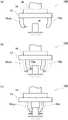
图1是示出本实施例的机械手100的大体结构的说明图。如图1(a)所示,本实施例的机械手100由设置有四根手指10a、10b的基台12、安装于基台12的负载传感器14、以及经由负载传感器14支承基台12的臂16等构成。四根手指10a、10b设置为每两根手指相对,其中的一根手指形成为在与所要把持的对象物接触的部分装入触点开关10s的接触检测指10b。另外,相对于接触检测指10b,将四根手指10a、10b中的未设置有触点开关10s的手指称作普通指10a。并且,在不区别普通指10a和接触检测指10b的情况下,将上述手指统称作手指10。FIG. 1 is an explanatory diagram showing a general configuration of a
在图1(b)中以从上方观察图1(a)中的机械手100的状态示出四根手指10的驱动机构。如图1(b)所示,在机械手100的基台12内置有两个移动部件20,四根手指10中相同朝向地设置的两根手指10从相同的移动部件20立起设置。并且,在各个移动部件20设置有齿条22,内置于基台12的中央的小齿轮24与上述齿条22嵌合。因此,当利用未图示的驱动马达使小齿轮24旋转时,各个移动部件20通过齿条小齿轮机构向相反方向移动相同的距离,其结果是,四根手指10中的相对的手指10相对于所要把持的对象物同时靠近或者远离相同的距离。另外,在本实施例中,构成齿条小齿轮机构的齿条22以及小齿轮24、控制齿条小齿轮机构的动作的未图示的控制电路与本发明中的“手指驱动机构”对应。FIG. 1( b ) shows the driving mechanism of the four fingers 10 in a state in which the
B、对象物的把持动作:B. The action of holding the object:
图2是示出本实施例的机械手100把持对象物W的动作的说明图。如上所述,由于四根手指10中相对的手指10彼此同时靠近或者远离相同的距离,因此,本实施例的机械手100相对于基台12总是在相同的位置(基台12的中心的正下方)把持对象物W。因此,在把持对象物W之前进行机械手100的对位,以使对象物W到达基台12的中心的正下方。在图2(a)中示出使机械手100相对于对象物W对位后的状态。FIG. 2 is an explanatory diagram showing the operation of the
通过从该状态使小齿轮24旋转,从而使四根手指10靠近对象物W。在使手指10靠近对象物W时,为了尽可能迅速地(短时间)靠近而进行位置控制。即,根据所要把持的对象物W的大小设定使手指10移动的目标位置,并控制小齿轮24的驱动马达所产生的转矩,以使手指10尽可能在短时间内到达该目标位置。另外,在本实施例的机械手100中,在所要把持的对象物W的大小未知的情况下,也可以将相对的手指10彼此最接近的位置(把持能够把持的最小的对象物W的位置)作为目标位置来进行位置控制。其理由之后叙述。From this state, the four fingers 10 are brought close to the object W by rotating the
当使四根手指10靠近对象物W时,如图2(b)所示,接触检测指10b最终会与对象物W接触,从而触点开关10s接通,由接触检测指10b检测到接触。进而,在利用接触检测指10b检测到接触之后,从使手指10向目标位置移动的控制方法(位置控制)切换至以恒定的力使手指10移动的控制方法(力控制)。另外,此时使手指10移动的力设定为如下大小的力:即使利用该力将手指10按压于对象物W,也能够不损伤对象物W地以适当的力把持对象物W。When the four fingers 10 are brought close to the object W, as shown in FIG. 2( b ), the
其结果是,在接触检测指10b与对象物W接触之后,四根手指10缓慢地(比接触检测指10b接触对象物W之前慢的速度)靠近对象物W。此时,设置于接触检测指10b的触点开关10s承受来自对象物W的反作用力,缩回手指10靠近对象物W的距离。进而,如图2(c)所示,最终能够实现四根手指10与对象物W接触并以适当的力把持对象物W。As a result, after the
图3是示出本实施例的机械手100把持对象物W时的触点开关10s的状态、负载传感器14的输出、以及小齿轮24的驱动马达所产生的转矩随着时间而变化的状态的时间图。如上所述,由于在开始把持动作之后立刻进行位置控制,因此,小齿轮24的驱动马达产生接近于最大额定转矩的大转矩,以使手指10尽可能在短时间内到达目标位置。之后,如图2(b)所示,当接触检测指10b与对象物W接触且触点开关10s接通时,从位置控制切换至力控制。在该力控制中,对驱动马达进行控制以使其产生规定为手指10能够以适当的力把持对象物W的规定转矩。3 is a graph showing the state of the
并且,当接触检测指10b与对象物W接触时,接触检测指10b所承受的反作用力传递至基台12,并且由负载传感器14检测到该反作用力。但是,如图2(c)所示,当形成四根手指10与对象物W接触的状态时,从各个手指10传递至基台12的反作用力相互抵消,从而负载传感器14检测不到反作用力。因此,在由负载传感器14检测的反作用力变得检测不到的阶段,可以判断为对象物W的把持结束。并且,由于在对象物W的把持结束之后仍需要继续保持对象物W,因此,小齿轮24的驱动马达继续产生恒定的转矩。另外,由于利用负载传感器14检测到的反作用力是将基台12从四根手指10承受的反作用力合成后的反作用力,因此,负载传感器14所检测的反作用力与本发明中的“合成反作用力”对应,负载传感器14与本发明中的“合成反作用力检测机构”对应。Then, when the
如此,本实施例中的机械手100利用位置控制使手指10迅速地靠近对象物W,并在接触检测指10b与对象物W接触之后切换至力控制,以使指10以适当的力把持对象物W。因此,上述机械手100能够迅速地以适当的力把持对象物W。并且,由于设定为使接触检测指10b比其他手指10(即普通指10a)先与对象物W接触并对该接触进行检测,一旦检测到接触之后从位置控制切换至力控制,因此,机械手100的控制也不会变得复杂。除此之外,由于只要在四根手指10中的任意一根接触检测指10b设置触点开关10s即可,因此,机械手100的结构也不会变得复杂。In this way, the
此外,在本实施例中,从以下方面也能够简化机械手100的控制。即,由于在把持对象物W之前使接触检测指10b与对象物W接触并将控制方法切换至力控制,因此,在四根手指10把持对象物W的时刻切换至力控制。因此,即使假设对象物W的大小是能够进行把持的最小的大小来进行位置控制,也能够不损伤对象物W地对其进行把持。因此,即使在对象物W的大小未知的情况下,控制也丝毫不会变得复杂。In addition, in this embodiment, the control of the
另外,在以上说明中,对在把持对象物W之前对机械手100或者对象物W进行定位以使机械手100相对于对象物W到达适当的位置的情况进行了说明。但是,还会由于某些原因发生机械手100与对象物W的相对位置偏离的情况。即使在这样的情况下,本实施例的机械手100也能够如下所述那样适当地把持对象物W。In addition, in the above description, the case where the
图4是示出在机械手100与对象物W的相对位置偏离的情况下,机械手100把持对象物W的状态的说明图。如图4(a)所示,当在机械手100相对于对象物W的相对位置偏离的状态下使四根手指10靠近对象物W时,如图4(b)所示,普通指10a比接触检测指10b先与对象物W接触。其结果是,普通指10a从对象物W承受的反作用力传递至机械手100的基台12,并被负载传感器14检测。但是,由于在该阶段,接触检测指10b未与对象物W接触,因此,触点开关10s保持断开状态。如之前使用图3所述,在机械手100相对于对象物W正确地定位的情况下,当利用负载传感器14检测到反作用力时,触点开关10s也变成接通。因此,在无论是否利用负载传感器14检测到反作用力,触点开关10s均未接通的情况下,可以判断为机械手100未相对于对象物W正确地定位。FIG. 4 is an explanatory view showing a state in which the
因此,在这样的情况下,中止手指10的驱动并修正机械手100的位置。在修正机械手100的位置时,只要使基台12朝向负载传感器14检测不到反作用力的方向移动规定的恒定量即可。进而,在使手指10靠近对象物W,普通指10a再次比接触检测指10b先与对象物W接触的情况(即,虽然触点开关10s未接通,但利用负载传感器14检测到反作用力的情况)下,再次修正机械手100的位置。如果反复进行上述操作,则最终能够使机械手100相对于对象物W正确地对位。Therefore, in such a case, the driving of the finger 10 is stopped and the position of the
或者,也可以在普通指10a比接触检测指10b先与对象物W接触的时刻,检测普通指10a(或者接触检测指10b)的移动量,并基于所得到的移动量来修正机械手100相对于对象物W的位置。即,在机械手100相对于对象物W的位置较大地偏离,且对象物W十分接近普通指10a的情况下,只要使手指10稍稍移动,普通指10a就会与对象物W接触。相反,如果机械手100的位置偏离较小,则在普通指10a与对象物W接触之前,手指10移动的距离也会增大。由此,基于普通指10a与对象物W接触之前的手指10的移动量,能够预测机械手100相对于对象物W的位置偏离的程度,并能够根据预测的位置偏离程度来预测对机械手100相对于对象物W的位置进行修正的修正量。其结果是,能够迅速地修正机械手100相对于对象物W的位置。Alternatively, it is also possible to detect the movement amount of the
此外,也可以像以下那样进行操作。可以首先使基台12朝向负载传感器14检测不到反作用力的方向移动,并检测在直至接触检测指10b与对象物W接触为止的期间内基台12的移动量,进而基于该检测结果来修正机械手100相对于对象物W的位置。这样,由于能够正确地掌握机械手100与对象物W之间的位置关系,因此,能够迅速地将机械手100修正到正确的位置。In addition, it is also possible to operate as follows. First, the
在图4(c)中,示出像以上那样修正机械手100相对于对象物W的位置的状态。进而,在修正机械手100的位置之后,能够与之前使用图2所述的方法完全相同地把持对象物W。即,如图4(d)所示,在接触检测指10b与对象物W接触之前,一边进行位置控制一边驱动四根手指10,并在接触检测指10b与对象物W接触之后切换至力控制。如此,四根手指10缓慢地靠近对象物W,如图4(e)所示最终形成以适当的力把持对象物W的状态。FIG. 4( c ) shows a state in which the position of the
图5是修正本实施例的机械手100相对于对象物W的位置后,由机械手100把持对象物W时的时间图。由于与之前使用图3所述的时间图相同,在开始把持动作之后立即进行位置控制,因此,小齿轮24的驱动马达产生接近最大额定转矩的大转矩,以使手指10尽可能在短时间内到达目标位置。并且,在此,由于设定为普通指10a比接触检测指10b先与对象物W接触,因此,在接触检测指10b的触点开关10s保持断开的状态下,由负载传感器14检测到反作用力。另外,负载传感器14的输出成为负值是由于下述原因:由于设置于与接触检测指10b相反一侧的普通指10a与对象物W接触,所以负载传感器14承受与图3所示的情况相反方向的反作用力。FIG. 5 is a timing chart when the
当在触点开关10s保持断开的状态下,由负载传感器14检测到反作用力时,停止手指10的移动。在图5所示的时间图中,为了使移动中的手指10迅速地停止而使小齿轮24的驱动马达产生反方向的转矩。进而,在使手指10停止并修正机械手100相对于对象物W的位置之后,再次使四根手指10朝向对象物W移动。之后,与之前使用图3所述的时间图相同。即,当使四根手指10靠近对象物W时,首先,接触检测指10b与对象物W接触,且触点开关10s接通,因此将手指10的驱动方法从位置控制切换为力控制。其结果是,在此之后四根手指10缓慢地靠近对象物W。并且,伴随着接触检测指10b与对象物W接触,负载传感器14也检测到反作用力。进而,当四根手指10全部与对象物W接触时,变得无法检测到负载传感器14的反作用力,从而形成对象物W的把持结束的状态。When a reaction force is detected by the
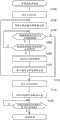
图6是为了控制本实施例的机械手100的把持动作而执行的对象物把持处理的流程图。控制机械手100的整体动作的未图示的控制电路执行图6所示的对象物把持处理,从而实现之前使用图2~图5所述的把持动作。FIG. 6 is a flowchart of object grasping processing executed to control the grasping operation of the
在对象物把持处理中,首先设定使四根手指10朝向对象物W移动时的目标位置(步骤S100)。如上所述,在所要把持的对象物W的大小已知的情况下,将把持该对象物W时的手指10的位置设定为目标位置。并且,在对象物W的大小未知的情况下,将对能够利用机械手100把持的最小的对象物W进行把持时的手指10的位置设定为目标位置。另外,为了简化控制,目标位置也可以固定于对能够把持的最小对象物W进行把持时的手指10的位置。In the object grasping process, first, target positions for moving the four fingers 10 toward the object W are set (step S100 ). As described above, when the size of the object W to be held is known, the position of the finger 10 when holding the object W is set as the target position. Furthermore, when the size of the object W is unknown, the position of the finger 10 when holding the smallest object W that can be grasped by the
接下来进行位置控制,以使手指10能够在短时间内移动到设定好的目标位置,并且开始驱动手指10(步骤S102)。另外,如上所述,在本实施例中,由于通过使小齿轮24旋转而使手指10移动,因此,控制使小齿轮24旋转的驱动马达所产生的转矩。Next, position control is performed so that the finger 10 can move to the set target position in a short time, and the finger 10 is started to be driven (step S102 ). In addition, as described above, in this embodiment, since the finger 10 is moved by rotating the
进而,判断接触检测指10b是否已与对象物W接触(触点开关10s是否接通)(步骤S104),在接触检测指10b未与对象物W接触的情况下(步骤S104:否),判断在负载传感器14中是否检测到反作用力(步骤S106)。在接触检测指10b或者普通指10a与对象物W接触之后,会在负载传感器14中检测到反作用力。因此,由于在负载传感器14中未检测到反作用力的情况(步骤S106:否),可以判断为未有任何手指10与对象物W接触,所以一边进行位置控制一边继续驱动手指10,并返回至步骤S104的处理来再次判断接触检测指10b是否已与对象物W接触。Furthermore, it is judged whether the
在反复进行这样的判断的过程中,接触检测指10b或者普通指10a最终会与对象物W接触。如上所述,如果机械手100相对于对象物W正确地被定位,则接触检测指10b比普通指10a先与对象物W接触。In the process of repeating such determinations, the
其结果是,在步骤S104中判断为“是”,接下来设定目标把持力(步骤S112)。在此,所谓目标把持力是指即使将手指10按压于对象物W也不会损伤对象物W,并且设定为能够牢固地把持对象物W的把持力。另外,在本实施例中,由于通过使小齿轮24旋转来使手指10移动,因此,设定目标把持力的操作与设定小齿轮24的驱动马达所产生的目标转矩的操作相同。进而,控制小齿轮24的驱动马达以使其产生设定好的目标转矩,从而在一边进行力控制一边开始驱动手指10之后(步骤S114),判断是否已检测不到负载传感器14的反作用力(步骤S116)。由于在检测到负载传感器14的反作用力的情况下(步骤S116:否),可以判断为把持仍未结束(四根手指10未与对象物W接触),因此,保持原样继续进行力控制。进而,在继续进行力控制的过程中,在全部四根手指10最终与对象物W接触而变得负载传感器14检测不到反作用力之后(步骤S116:是),结束图6所示的对象物把持处理。另外,在结束对象物把持处理之后,成为手指10仍以目标把持力被按压于对象物W来保持所把持的对象物W的状态。As a result, it is judged as "Yes" in step S104, and then the target gripping force is set (step S112). Here, the target gripping force refers to a gripping force that can firmly grip the object W without damaging the object W even if the finger 10 is pressed against it. In addition, in this embodiment, since the finger 10 is moved by rotating the
以上,对机械手100相对于对象物W被正确地定位,并且接触检测指10b比普通指10a先与对象物W接触的情况(在步骤S104中判断为“是”的情况)进行了说明。与此相对,在普通指10a比接触检测指10b先与对象物W接触的情况下,由于在步骤S106中判断为“是”,因此,停止驱动手指10(步骤S108)。此时,为了使移动中的手指10迅速地停止,可以使小齿轮24的驱动马达产生反方向的转矩(参照图5)。In the above, the case where the
接下来,修正机械手100相对于对象物W的位置(步骤S110)。在修正位置时,可以使机械手100移动,也可以使对象物W移动。并且,使机械手100(或者对象物W)移动的方向为检测不到由负载传感器14检测的反作用力的方向。此外,关于移动量,可以是预先设定好的固定量,或者也可以是利用上述方法(利用负载传感器14检测到反作用力之前的手指10的移动量的方法、利用接触检测指10b与对象物W接触之前使基台12移动时的基台12的移动量的方法)预测的移动量。Next, the position of the
像以上那样修正机械手100相对于对象物W的位置之后(步骤S110),再次开始利用位置控制进行的手指10的驱动(步骤S102)。进而,如上所述,在接触检测指10b与对象物W接触(步骤S104:是)、或者负载传感器14检测到反作用力之前(步骤S106:是),继续利用位置控制进行的手指10的驱动。其结果是,在负载传感器14检测到反作用力的情况下(步骤S106:是),在再次停止手指10的驱动并修正机械手100的位置之后(步骤S108、S110),再次利用位置控制进行的手指10的驱动(步骤S102)。与此相对,在接触检测指10b与对象物W接触的情况下(步骤S104:是),如上所述,在设定目标把持力之后(步骤S112),一边进行力控制以便达到已设定的目标把持力,一边驱动手指10(步骤S114)。进而,在负载传感器14检测不到反作用力之后(步骤S116:是),判断为对象物W的把持结束,并结束图6中的对象物把持处理。After the position of the
本实施例的机械手100通过进行以上处理,能够迅速地以适当的力把持对象物W。并且,即使在机械手100相对于对象物W的位置偏离的情况下,也能够修正机械手100的位置,并准确地把持对象物W。The
C、变形例:C. Variations:
在上述实施例中存在几个变形例。以下,对这些变形例简单地进行说明。另外,在关于变形例的说明中,省略与上述实施例相同的结构的说明,仅对不同点进行说明。There are several modified examples in the above-described embodiments. Hereinafter, these modified examples will be briefly described. In addition, in the description of the modified example, the description of the same configuration as that of the above-mentioned embodiment will be omitted, and only the different points will be described.
上述实施例中的接触检测指10b,以在与对象物W接触的部分设置有触点开关10s的接触检测指的情况进行了说明。但是,如果接触检测指10b是比普通指10a先与对象物W接触,而且至少在普通指10a与对象物W接触之前的期间不产生损伤对象物W那样过大的力的手指10,则也可以采用其他实施方式。The
图7是举例示出搭载有其他方式的接触检测指的各种变形例的机械手的说明图。在图7(a)所例示的变形例的机械手110中,接触检测指30b构成为在指节32的部分弯曲,且被内置于指节32的弹簧施力而在初始状态下形成向内侧弯曲的状态。进而,当接触检测指30b与对象物W接触,且接触检测指30b因来自对象物W的反作用力而在指节32的部分稍稍向外侧旋转时,设置于指节32的内部的未图示的触点开关接通。之后,使接触检测指30b随着靠近对象物W而在指节32的部分进一步向外侧旋转,亦可以此来使接触检测指30b变形。FIG. 7 is an explanatory diagram showing examples of manipulators equipped with various modified examples of contact detection fingers in other forms. In the
另外,在图7(b)所例示的变形例的机械手120中,接触检测指34b整体构成为通过安装于基台12的安装部分(实际上安装于移动部件20的安装部分)滑动,并在初始状态下由弹簧施力而形成向内侧滑动的状态。进而,当接触检测指34b与对象物W接触,且接触检测指34b因来自对象物W的反作用力而稍稍向外侧滑动时,设置于基台12的未图示的触点开关接通。之后,可以使接触检测指34b随着靠近对象物W而向外侧滑动。In addition, in the
或者,在图7(c)所例示的变形例的机械手130中,接触检测指36b由比较容易变形的弹性部件构成,并在与对象物W接触的部分设置有压力传感器10t。进而,当接触检测指36b与对象物W接触时,利用压力传感器10t的输出检测接触。之后,可以使接触检测指36b随着靠近对象物W而整体变形。Alternatively, in the modified
并且,在上述实施例或者变形例中,对多根手指10相对地设置的情况进行了说明。但是,多根手指10无需一定相对地设置,例如,可以如图8所例示那样将多根手指10朝向中心地设置。In addition, in the above-mentioned embodiment or modified example, the case where a plurality of fingers 10 are arranged facing each other has been described. However, the plurality of fingers 10 need not necessarily be arranged facing each other. For example, the plurality of fingers 10 may be arranged toward the center as illustrated in FIG. 8 .
D、应用例:D. Application example:
如上所述,本实施例或者变形例的机械手100、110、120、130能够迅速地以适当的力把持对象物W,并且结构、控制不复杂。因此,如图9所示,如果搭载本实施例或者变形例的机械手100、110、120、130,则能够迅速地以适当的力把持对象物W,并且能够实现结构、控制简单的机器人500。As described above, the
以上,虽然对本实施例的机械手以及机器人进行了说明,但本发明不限定于上述实施例,而能够在不脱离其宗旨的范围以各种实施方式加以实施。符号说明:As mentioned above, although the manipulator and robot of this Example were demonstrated, this invention is not limited to the said Example, It can implement in various embodiment within the range which does not deviate from the gist. Symbol Description:
10...手指;10a...普通指;10b...接触检测指;10s...触点开关;10t...压力传感器;12...基台;14...负载传感器;16...臂;20...移动部件;22...齿条;24...小齿轮;30b...接触检测指;32...指节;34b...接触检测指;36b...接触检测指;100、110、120、130...机械手;500...机器人;W...对象物10...finger; 10a...ordinary finger; 10b...contact detection finger; 10s...contact switch; 10t...pressure sensor; 12...abutment; 14...load sensor; 16...arm; 20...moving part; 22...rack; 24...pinion; 30b...contact detection finger; 32...knuckle; 34b...contact detection finger; 36b...contact detection finger; 100, 110, 120, 130...manipulator; 500...robot; W...object
Claims (3)
Translated fromChineseApplications Claiming Priority (2)
| Application Number | Priority Date | Filing Date | Title |
|---|---|---|---|
| JP2011-105007 | 2011-05-10 | ||
| JP2011105007AJP5834478B2 (en) | 2011-05-10 | 2011-05-10 | robot |
Publications (2)
| Publication Number | Publication Date |
|---|---|
| CN102773865Atrue CN102773865A (en) | 2012-11-14 |
| CN102773865B CN102773865B (en) | 2015-11-18 |
Family
ID=47119081
Family Applications (1)
| Application Number | Title | Priority Date | Filing Date |
|---|---|---|---|
| CN201210140294.9AExpired - Fee RelatedCN102773865B (en) | 2011-05-10 | 2012-05-08 | Manipulator and robot |
Country Status (3)
| Country | Link |
|---|---|
| US (1) | US8897918B2 (en) |
| JP (1) | JP5834478B2 (en) |
| CN (1) | CN102773865B (en) |
Cited By (13)
| Publication number | Priority date | Publication date | Assignee | Title |
|---|---|---|---|---|
| CN104400790A (en)* | 2013-11-26 | 2015-03-11 | 佛山市科信达机器人技术与装备有限公司 | Mechanical clamping arm for carrying ceramic tiles |
| CN105034025A (en)* | 2014-04-30 | 2015-11-11 | 发那科株式会社 | Safety monitoring device for robots |
| CN105415370A (en)* | 2014-09-16 | 2016-03-23 | 发那科株式会社 | Article Pickup Apparatus For Picking Up Randomly Piled Articles |
| CN105775724A (en)* | 2016-03-14 | 2016-07-20 | 无为县环江铜业有限公司 | Gripper used for vertical carrying of large-sized copper pipes |
| CN105835056A (en)* | 2015-02-03 | 2016-08-10 | 佳能株式会社 | Robot hand controlling method and robotics device |
| CN107932539A (en)* | 2017-12-23 | 2018-04-20 | 安徽航大智能科技有限公司 | A kind of manipulator for capturing multilayer new energy battery modules and its sampling plate |
| CN108972540A (en)* | 2017-05-30 | 2018-12-11 | 佳能株式会社 | Robot, the control method of robot and robot device |
| CN109927058A (en)* | 2017-12-05 | 2019-06-25 | 丰田自动车株式会社 | Grip device grasps determination method and grasps decision procedure |
| CN109968348A (en)* | 2017-12-28 | 2019-07-05 | 深圳市优必选科技有限公司 | Robot control method, device and terminal equipment |
| CN110744551A (en)* | 2019-11-20 | 2020-02-04 | 上海非夕机器人科技有限公司 | Robot clamping jaw movement control method and device, robot and storage device |
| CN111902247A (en)* | 2018-03-23 | 2020-11-06 | 爱沛股份有限公司 | Electric manipulator and method of holding object |
| CN113021341A (en)* | 2021-03-18 | 2021-06-25 | 深圳市科服信息技术有限公司 | Robot based on 5G article identification and automatic transfer transportation |
| CN114800541A (en)* | 2021-01-28 | 2022-07-29 | 精工爱普生株式会社 | Cable terminal detection method and manipulator |
Families Citing this family (32)
| Publication number | Priority date | Publication date | Assignee | Title |
|---|---|---|---|---|
| JP5861255B2 (en)* | 2011-01-12 | 2016-02-16 | セイコーエプソン株式会社 | Robot hand and robot |
| JP5717503B2 (en)* | 2011-03-30 | 2015-05-13 | 富士重工業株式会社 | Press product inspection equipment |
| JP5834480B2 (en)* | 2011-05-11 | 2015-12-24 | セイコーエプソン株式会社 | Robot hand and robot |
| JP5516612B2 (en)* | 2012-01-24 | 2014-06-11 | 株式会社安川電機 | Robot system |
| JP6039187B2 (en)* | 2012-02-03 | 2016-12-07 | キヤノン株式会社 | Assembly apparatus, gripping hand, and article assembling method |
| JP2014108466A (en)* | 2012-11-30 | 2014-06-12 | Fanuc Ltd | Electric hand with force sensor |
| JP6454960B2 (en)* | 2013-10-31 | 2019-01-23 | セイコーエプソン株式会社 | Robot, robot system, robot controller |
| US20150151433A1 (en)* | 2013-12-02 | 2015-06-04 | Harris Corporation | Compact robotic gripper |
| US10329042B2 (en)* | 2015-03-20 | 2019-06-25 | Seiko Epson Corporation | Packing apparatus and packing method |
| US10272568B2 (en)* | 2015-09-17 | 2019-04-30 | Canon Kabushiki Kaisha | Robot apparatus, robot controlling method, program, recording medium, and assembly manufacturing method |
| JP6657826B2 (en)* | 2015-11-16 | 2020-03-04 | 株式会社デンソーウェーブ | Gripping device |
| WO2017116953A1 (en)* | 2015-12-30 | 2017-07-06 | Baxter Corporation Englewood | Syringe gripping apparatus and method |
| JP2017196705A (en)* | 2016-04-28 | 2017-11-02 | セイコーエプソン株式会社 | Robot and robot system |
| JP2019018280A (en)* | 2017-07-14 | 2019-02-07 | Thk株式会社 | Holding system |
| US10814494B2 (en) | 2017-09-26 | 2020-10-27 | Toyota Research Institute, Inc. | Robotic gripper fingers |
| JP7069512B2 (en)* | 2017-11-15 | 2022-05-18 | Thk株式会社 | Gripping system and its control method |
| CN109968349B (en)* | 2017-12-28 | 2021-04-16 | 深圳市优必选科技有限公司 | Robot control method and device and terminal equipment |
| USD883351S1 (en) | 2018-05-10 | 2020-05-05 | Robotiq Inc. | Robotic end effector |
| WO2019218057A1 (en)* | 2018-05-13 | 2019-11-21 | Robotiq Inc. | Robotic gripper |
| DK180068B1 (en)* | 2018-07-16 | 2020-03-19 | Onrobot A/S | Safe Collaborative Gripping Device |
| EP3597376A1 (en)* | 2018-07-17 | 2020-01-22 | Baumer Electric AG | Gripper system |
| JP7147419B2 (en)* | 2018-09-26 | 2022-10-05 | オムロン株式会社 | end effector device |
| US20210031373A1 (en)* | 2019-08-02 | 2021-02-04 | Dextrous Robotics, Inc. | Robotic manipulators |
| CN110696020A (en)* | 2019-09-05 | 2020-01-17 | 上海大学 | Self-adaptive underactuated manipulator |
| CN110640771A (en)* | 2019-09-11 | 2020-01-03 | 哈尔滨工程大学 | Mechanical claw for grabbing bar underwater |
| CN110605717A (en)* | 2019-09-18 | 2019-12-24 | 北京三快在线科技有限公司 | Mechanical arm, unmanned aerial vehicle automatic battery replacement system and mechanical arm control method |
| USD1039578S1 (en)* | 2020-04-19 | 2024-08-20 | Tata Consultancy Services Limited | Robot gripper |
| US11685058B2 (en)* | 2020-11-23 | 2023-06-27 | Mitsubishi Electric Research Laboratories Inc. | Soft robotic tentacle gripper |
| CN117769486A (en)* | 2021-05-24 | 2024-03-26 | 戴弗根特技术有限公司 | Robot gripper device |
| CN113816127A (en)* | 2021-07-09 | 2021-12-21 | 杭州君辰机器人有限公司 | Clamping mechanism |
| JP2023075993A (en)* | 2021-11-22 | 2023-06-01 | 株式会社日立製作所 | Rack gripping device |
| CN115042114B (en)* | 2022-07-20 | 2024-03-15 | 湖南省东海五金工具制造有限公司 | Spanner capable of realizing double contact surface locking rotation |
Citations (12)
| Publication number | Priority date | Publication date | Assignee | Title |
|---|---|---|---|---|
| US4561825A (en)* | 1982-03-26 | 1985-12-31 | Hitachi, Ltd. | Apparatus for fetching component parts |
| US4579380A (en)* | 1983-12-06 | 1986-04-01 | Carnegie-Mellon University | Servo robot gripper |
| US4715773A (en)* | 1985-06-04 | 1987-12-29 | Clemson University | Method and apparatus for repositioning a mislocated object with a robot hand |
| US4872803A (en)* | 1983-11-30 | 1989-10-10 | Fujitsu Limited | Force controlling system |
| CN1052445A (en)* | 1989-12-12 | 1991-06-26 | 杭州电子工业学院 | Three-sense manipulator |
| CN1290591A (en)* | 2000-10-24 | 2001-04-11 | 中国科学院合肥智能机械研究所 | Multi-sensor robot paw and method |
| JP2003245883A (en)* | 2002-02-25 | 2003-09-02 | Gifu Univ | Robot hand, gripping control method of robot hand, and robot and robot control method |
| CN1757490A (en)* | 2004-10-08 | 2006-04-12 | 发那科株式会社 | Hand robot |
| JP3871293B2 (en)* | 1999-03-10 | 2007-01-24 | 学校法人慶應義塾 | Object gripping control method by hand or manipulator |
| JP4228871B2 (en)* | 2002-10-29 | 2009-02-25 | パナソニック株式会社 | Robot grip control device and robot grip control method |
| WO2010074045A1 (en)* | 2008-12-26 | 2010-07-01 | 学校法人 日本大学 | Robot hand system with gripping section |
| CN102037340A (en)* | 2008-05-29 | 2011-04-27 | 谐波传动系统有限公司 | Complex sensor and robot hand |
Family Cites Families (10)
| Publication number | Priority date | Publication date | Assignee | Title |
|---|---|---|---|---|
| JPS63318280A (en)* | 1987-06-16 | 1988-12-27 | 富士通株式会社 | How to detect the opening/closing width of a two-finger robot hand |
| JPH0294096A (en) | 1988-09-29 | 1990-04-04 | Mitsubishi Electric Corp | semiconductor memory circuit |
| JPH04146094A (en)* | 1990-10-08 | 1992-05-20 | Matsushita Electric Ind Co Ltd | Servo hand and work holding method |
| JPH05318363A (en)* | 1992-05-21 | 1993-12-03 | Sanyo Electric Co Ltd | Method for controlling robot |
| JP4117091B2 (en)* | 1999-09-29 | 2008-07-09 | アロカ株式会社 | Test tube conveyor |
| JP2002355785A (en) | 2001-05-31 | 2002-12-10 | Yukio Saito | Artificial hand and artificial hand control system |
| JP2003175481A (en)* | 2001-12-11 | 2003-06-24 | Ricoh Co Ltd | Handling equipment |
| JP4200490B2 (en) | 2003-11-18 | 2008-12-24 | 学校法人日本大学 | Touch notification device |
| JP4621827B2 (en)* | 2004-03-09 | 2011-01-26 | 財団法人名古屋産業科学研究所 | Optical tactile sensor, sensing method using optical tactile sensor, sensing system, object operation force control method, object operation force control device, object gripping force control device, and robot hand |
| JP2009066685A (en) | 2007-09-11 | 2009-04-02 | Sony Corp | Robot device, and control method for robot device |
- 2011
- 2011-05-10JPJP2011105007Apatent/JP5834478B2/ennot_activeExpired - Fee Related
- 2012
- 2012-05-08CNCN201210140294.9Apatent/CN102773865B/ennot_activeExpired - Fee Related
- 2012-05-09USUS13/467,547patent/US8897918B2/ennot_activeExpired - Fee Related
Patent Citations (12)
| Publication number | Priority date | Publication date | Assignee | Title |
|---|---|---|---|---|
| US4561825A (en)* | 1982-03-26 | 1985-12-31 | Hitachi, Ltd. | Apparatus for fetching component parts |
| US4872803A (en)* | 1983-11-30 | 1989-10-10 | Fujitsu Limited | Force controlling system |
| US4579380A (en)* | 1983-12-06 | 1986-04-01 | Carnegie-Mellon University | Servo robot gripper |
| US4715773A (en)* | 1985-06-04 | 1987-12-29 | Clemson University | Method and apparatus for repositioning a mislocated object with a robot hand |
| CN1052445A (en)* | 1989-12-12 | 1991-06-26 | 杭州电子工业学院 | Three-sense manipulator |
| JP3871293B2 (en)* | 1999-03-10 | 2007-01-24 | 学校法人慶應義塾 | Object gripping control method by hand or manipulator |
| CN1290591A (en)* | 2000-10-24 | 2001-04-11 | 中国科学院合肥智能机械研究所 | Multi-sensor robot paw and method |
| JP2003245883A (en)* | 2002-02-25 | 2003-09-02 | Gifu Univ | Robot hand, gripping control method of robot hand, and robot and robot control method |
| JP4228871B2 (en)* | 2002-10-29 | 2009-02-25 | パナソニック株式会社 | Robot grip control device and robot grip control method |
| CN1757490A (en)* | 2004-10-08 | 2006-04-12 | 发那科株式会社 | Hand robot |
| CN102037340A (en)* | 2008-05-29 | 2011-04-27 | 谐波传动系统有限公司 | Complex sensor and robot hand |
| WO2010074045A1 (en)* | 2008-12-26 | 2010-07-01 | 学校法人 日本大学 | Robot hand system with gripping section |
Cited By (23)
| Publication number | Priority date | Publication date | Assignee | Title |
|---|---|---|---|---|
| CN104400790A (en)* | 2013-11-26 | 2015-03-11 | 佛山市科信达机器人技术与装备有限公司 | Mechanical clamping arm for carrying ceramic tiles |
| CN105034025A (en)* | 2014-04-30 | 2015-11-11 | 发那科株式会社 | Safety monitoring device for robots |
| CN105034025B (en)* | 2014-04-30 | 2016-10-12 | 发那科株式会社 | The security monitoring device of robot |
| US9682478B2 (en) | 2014-04-30 | 2017-06-20 | Fanuc Corporation | Safety monitoring device for robot gripping and carrying workpiece |
| CN105415370A (en)* | 2014-09-16 | 2016-03-23 | 发那科株式会社 | Article Pickup Apparatus For Picking Up Randomly Piled Articles |
| CN105835056A (en)* | 2015-02-03 | 2016-08-10 | 佳能株式会社 | Robot hand controlling method and robotics device |
| CN105835056B (en)* | 2015-02-03 | 2019-04-16 | 佳能株式会社 | The control method of robot and robot device |
| CN105775724A (en)* | 2016-03-14 | 2016-07-20 | 无为县环江铜业有限公司 | Gripper used for vertical carrying of large-sized copper pipes |
| US11192255B2 (en) | 2017-05-30 | 2021-12-07 | Canon Kabushiki Kaisha | Robot hand, control method of robot hand, and robot apparatus |
| CN108972540B (en)* | 2017-05-30 | 2022-05-24 | 佳能株式会社 | Robot hand, robot hand control method, and robot apparatus |
| CN108972540A (en)* | 2017-05-30 | 2018-12-11 | 佳能株式会社 | Robot, the control method of robot and robot device |
| CN109927058A (en)* | 2017-12-05 | 2019-06-25 | 丰田自动车株式会社 | Grip device grasps determination method and grasps decision procedure |
| CN107932539A (en)* | 2017-12-23 | 2018-04-20 | 安徽航大智能科技有限公司 | A kind of manipulator for capturing multilayer new energy battery modules and its sampling plate |
| CN107932539B (en)* | 2017-12-23 | 2024-01-12 | 安徽航大智能科技有限公司 | Mechanical arm for grabbing multilayer new energy battery module and data sampling plate thereof |
| CN109968348B (en)* | 2017-12-28 | 2021-04-16 | 深圳市优必选科技有限公司 | Robot control method and device and terminal equipment |
| CN109968348A (en)* | 2017-12-28 | 2019-07-05 | 深圳市优必选科技有限公司 | Robot control method, device and terminal equipment |
| CN111902247A (en)* | 2018-03-23 | 2020-11-06 | 爱沛股份有限公司 | Electric manipulator and method of holding object |
| CN110744551A (en)* | 2019-11-20 | 2020-02-04 | 上海非夕机器人科技有限公司 | Robot clamping jaw movement control method and device, robot and storage device |
| CN114800541A (en)* | 2021-01-28 | 2022-07-29 | 精工爱普生株式会社 | Cable terminal detection method and manipulator |
| CN114800541B (en)* | 2021-01-28 | 2023-12-19 | 精工爱普生株式会社 | Cable terminal detection method and robot |
| US12168298B2 (en) | 2021-01-28 | 2024-12-17 | Seiko Epson Corporation | Cable terminal end detection method and hand |
| CN113021341A (en)* | 2021-03-18 | 2021-06-25 | 深圳市科服信息技术有限公司 | Robot based on 5G article identification and automatic transfer transportation |
| CN113021341B (en)* | 2021-03-18 | 2022-04-19 | 周宗平 | Robot based on 5G article identification and automatic transfer transportation |
Also Published As
| Publication number | Publication date |
|---|---|
| JP2012236237A (en) | 2012-12-06 |
| US20120290133A1 (en) | 2012-11-15 |
| JP5834478B2 (en) | 2015-12-24 |
| US8897918B2 (en) | 2014-11-25 |
| CN102773865B (en) | 2015-11-18 |
Similar Documents
| Publication | Publication Date | Title |
|---|---|---|
| CN102773865B (en) | Manipulator and robot | |
| JP6454960B2 (en) | Robot, robot system, robot controller | |
| US9375838B2 (en) | Grip apparatus, control method for the grip apparatus, and robot manipulator | |
| US10283395B2 (en) | Substrate gripping hand and substrate transfer apparatus | |
| US20090025199A1 (en) | Flexible workpiece assembling method | |
| KR20120053274A (en) | Method of controlling robot | |
| US20120286536A1 (en) | Robot hand and robot | |
| JP2014176940A (en) | Robot system, method for controlling robot and method for manufacturing workpiece | |
| WO2020066061A1 (en) | End effector and end effector device | |
| JP2011240422A (en) | Robot hand and robot | |
| WO2020066063A1 (en) | End effector device | |
| JP2013233614A (en) | Robot hand, and robot | |
| WO2017203945A1 (en) | Workpiece gripping device and workpiece gripping method | |
| JP5834491B2 (en) | Robot hand and robot | |
| JP2016203280A5 (en) | ||
| JP2016043455A (en) | Robot and robot system | |
| JP2022115341A (en) | Cable termination detection method and hand | |
| JP2015205383A (en) | Work-piece transport device with positioning mechanism | |
| KR102709375B1 (en) | Method for Assembling Industrial Parts Using Dual Arm Robot Manipulator | |
| JP2016087749A (en) | Robot hand | |
| US11541541B2 (en) | Gripping system | |
| US20230415337A1 (en) | Grip position setting method and robot system | |
| JP5360155B2 (en) | Robot system | |
| JP6314429B2 (en) | Robot, robot system, and robot controller | |
| JPH10249767A (en) | Mobile object gripping device and control method thereof |
Legal Events
| Date | Code | Title | Description |
|---|---|---|---|
| C06 | Publication | ||
| PB01 | Publication | ||
| C10 | Entry into substantive examination | ||
| SE01 | Entry into force of request for substantive examination | ||
| C14 | Grant of patent or utility model | ||
| GR01 | Patent grant | ||
| CF01 | Termination of patent right due to non-payment of annual fee | ||
| CF01 | Termination of patent right due to non-payment of annual fee | Granted publication date:20151118 Termination date:20170508 |