CN102768225B - High-accuracy method for testing thermal interface material - Google Patents
High-accuracy method for testing thermal interface materialDownload PDFInfo
- Publication number
- CN102768225B CN102768225BCN201210280027.1ACN201210280027ACN102768225BCN 102768225 BCN102768225 BCN 102768225BCN 201210280027 ACN201210280027 ACN 201210280027ACN 102768225 BCN102768225 BCN 102768225B
- Authority
- CN
- China
- Prior art keywords
- temperature
- thermal
- heat
- test
- contact
- Prior art date
- Legal status (The legal status is an assumption and is not a legal conclusion. Google has not performed a legal analysis and makes no representation as to the accuracy of the status listed.)
- Active
Links
- 238000012360testing methodMethods0.000titleclaimsabstractdescription115
- 238000000034methodMethods0.000titleclaimsabstractdescription43
- 239000000463materialSubstances0.000titleclaimsabstractdescription39
- 238000010438heat treatmentMethods0.000claimsabstractdescription29
- 238000004364calculation methodMethods0.000claimsabstractdescription15
- 238000004154testing of materialMethods0.000claimsabstractdescription10
- 238000002360preparation methodMethods0.000claimsabstractdescription4
- 230000002457bidirectional effectEffects0.000claimsabstractdescription3
- 238000001816coolingMethods0.000claimsdescription17
- 238000012625in-situ measurementMethods0.000claimsdescription6
- 239000010421standard materialSubstances0.000claimsdescription6
- 238000013213extrapolationMethods0.000claimsdescription3
- 238000005259measurementMethods0.000abstractdescription8
- 238000009529body temperature measurementMethods0.000abstractdescription7
- 239000000523sampleSubstances0.000description9
- 230000005855radiationEffects0.000description6
- 229910000831SteelInorganic materials0.000description4
- SBYXRAKIOMOBFF-UHFFFAOYSA-Ncopper tungstenChemical compound[Cu].[W]SBYXRAKIOMOBFF-UHFFFAOYSA-N0.000description4
- 238000000691measurement methodMethods0.000description4
- 239000010959steelSubstances0.000description4
- CSCPPACGZOOCGX-UHFFFAOYSA-NAcetoneChemical compoundCC(C)=OCSCPPACGZOOCGX-UHFFFAOYSA-N0.000description3
- 238000010586diagramMethods0.000description3
- 230000001052transient effectEffects0.000description3
- OKTJSMMVPCPJKN-UHFFFAOYSA-NCarbonChemical compound[C]OKTJSMMVPCPJKN-UHFFFAOYSA-N0.000description2
- 229910000881Cu alloyInorganic materials0.000description2
- 229910002804graphiteInorganic materials0.000description2
- 239000010439graphiteSubstances0.000description2
- 238000003780insertionMethods0.000description2
- 230000037431insertionEffects0.000description2
- 238000010998test methodMethods0.000description2
- XLYOFNOQVPJJNP-UHFFFAOYSA-NwaterSubstancesOXLYOFNOQVPJJNP-UHFFFAOYSA-N0.000description2
- 238000003466weldingMethods0.000description2
- RYGMFSIKBFXOCR-UHFFFAOYSA-NCopperChemical compound[Cu]RYGMFSIKBFXOCR-UHFFFAOYSA-N0.000description1
- LFQSCWFLJHTTHZ-UHFFFAOYSA-NEthanolChemical compoundCCOLFQSCWFLJHTTHZ-UHFFFAOYSA-N0.000description1
- 230000003471anti-radiationEffects0.000description1
- 230000006835compressionEffects0.000description1
- 238000007906compressionMethods0.000description1
- 229910052802copperInorganic materials0.000description1
- 239000010949copperSubstances0.000description1
- 238000009795derivationMethods0.000description1
- 230000005284excitationEffects0.000description1
- 230000004907fluxEffects0.000description1
- 238000009413insulationMethods0.000description1
- WABPQHHGFIMREM-UHFFFAOYSA-Nlead(0)Chemical compound[Pb]WABPQHHGFIMREM-UHFFFAOYSA-N0.000description1
- 230000007774longtermEffects0.000description1
- 230000000704physical effectEffects0.000description1
- 238000001931thermographyMethods0.000description1
- 239000010409thin filmSubstances0.000description1
- WFKWXMTUELFFGS-UHFFFAOYSA-NtungstenChemical compound[W]WFKWXMTUELFFGS-UHFFFAOYSA-N0.000description1
- 229910052721tungstenInorganic materials0.000description1
- 239000010937tungstenSubstances0.000description1
- 238000004506ultrasonic cleaningMethods0.000description1
Images


Landscapes
- Investigating Or Analyzing Materials Using Thermal Means (AREA)
Abstract
Translated fromChinese
Description
Translated fromChinese技术领域technical field
本发明属于测试技术领域,具体涉及一种接触热阻测试方法,适用于对常用材料的界面接触热阻的测试,尤其适用于对热界面材料的性能测试。The invention belongs to the technical field of testing, and in particular relates to a contact thermal resistance test method, which is suitable for testing the interface thermal resistance of commonly used materials, especially for performance testing of thermal interface materials.
背景技术Background technique
接触热阻是一个受材料物性、机械特性、表面形貌、接触压力、温度、间隙材料等众多因素影响的参数。根据实验热流是否稳定,一般把接触热阻测量方法分为瞬态法和稳态法。瞬态法也是一种常用的接触热阻实验测量方法,其主要包括激光光热测量法、热成像法、“flash”闪光法、激光光声法等,其中激光光热测量法又包含调制光热法和热扫描法,调制光热法又有光热幅值法、光热相位法和脉冲法之分。虽然各种瞬态法虽宜于快速测量且可测量小到纳米数量级的薄膜,但其测量过程易受各种因素影响,且公式推导相对复杂,测量精度也较难保证。因此,界面接触热阻测量方法最常用的是稳态法:在两接触样品上维持一定的温差,测量两样品轴向上的温度值,再由傅里叶定律外推至接触界面处从而得到界面上的温差;热流量可由热流量计测量或由样品材料的热导率和温度梯度计算得到,从而R=|T1-T2|/Q。稳态接触热阻测试方法多是和美国国家标准ASTMD5470-06的测试标准设备相类似,但多有文献指出由于温度测量的不确定性误差和热损失误差很难保证对界面接触热阻有足够高的测量精度。Contact thermal resistance is a parameter affected by many factors such as material properties, mechanical properties, surface morphology, contact pressure, temperature, and gap material. According to whether the experimental heat flow is stable, the contact thermal resistance measurement methods are generally divided into transient method and steady state method. Transient method is also a commonly used experimental measurement method of thermal contact resistance, which mainly includes laser photothermal measurement method, thermal imaging method, "flash" flash method, laser photoacoustic method, etc., and laser photothermal measurement method also includes modulated light Thermal method and thermal scanning method, modulated photothermal method is divided into photothermal amplitude method, photothermal phase method and pulse method. Although various transient methods are suitable for rapid measurement and can measure thin films as small as nanometers, the measurement process is easily affected by various factors, and the formula derivation is relatively complicated, and the measurement accuracy is difficult to guarantee. Therefore, the most commonly used method for measuring interface thermal resistance is the steady-state method: maintain a certain temperature difference between the two contact samples, measure the axial temperature values of the two samples, and then extrapolate to the contact interface by Fourier's law to obtain The temperature difference on the interface; the heat flow can be measured by a heat flow meter or calculated from the thermal conductivity and temperature gradient of the sample material, so that R=|T1-T2|/Q. Most of the steady-state contact thermal resistance test methods are similar to the test standard equipment of the American National Standard ASTMD5470-06, but many documents point out that due to the uncertainty error of temperature measurement and heat loss error, it is difficult to ensure sufficient contact thermal resistance at the interface. High measurement accuracy.
发明内容Contents of the invention
本发明的目的在于提供一种高精度热界面材料测试方法,通过正反方向的热流测试消除温度测量的不确定性误差,从而实现高精度的测量热界面材料的界面接触热阻和当量导热系数。The purpose of the present invention is to provide a high-precision thermal interface material testing method, which eliminates the uncertainty error of temperature measurement through positive and negative heat flow tests, thereby realizing high-precision measurement of the interface contact thermal resistance and equivalent thermal conductivity of thermal interface materials .
实现本发明目的的技术解决方案为:一种高精度热界面材料测试方法,所述方法包括以下步骤:The technical solution to achieve the purpose of the present invention is: a high-precision thermal interface material testing method, the method includes the following steps:
第一步,测试设备的准备和测试热流量计测试点的选取:The first step is the preparation of test equipment and the selection of test points for testing heat flowmeters:
加工出两标准材料的热流量计,将热流量计竖直安装在两个上下对称设置的加热制冷套之间,在两加热制冷套上设置有应力加载装置,所述的热流量计上设置有温度传感器,温度传感器与数据采集系统连接,用于测试热流量计的轴向温度;Heat flow meters of two standard materials are processed, and the heat flow meters are vertically installed between two heating and cooling jackets arranged symmetrically up and down. Stress loading devices are arranged on the two heating and cooling jackets, and the heat flow meters are set There is a temperature sensor, and the temperature sensor is connected with the data acquisition system for testing the axial temperature of the heat flow meter;
热流量计上测试点之间的位置满足如下关系:以两热流量计纵轴方向上的接触界面截面位置为对称面,两热流量计上的测试点位置完全对称,每个热流量计从下端面到上端面之间均设置n个测试点,每个热流量计上相邻两个测试点之间的轴向距离相等,测试点之间的距离为dx;The positions of the test points on the heat flowmeters satisfy the following relationship: taking the cross-sectional position of the contact interface in the direction of the longitudinal axis of the two heat flowmeters as the symmetry plane, the positions of the test points on the two heat flowmeters are completely symmetrical, and each heat flowmeter starts from Set n test points between the lower end surface and the upper end surface, the axial distance between two adjacent test points on each heat flowmeter is equal, and the distance between the test points is dx;
第二步,加载压应力,正向对热流量计加热:The second step is to load the compressive stress and heat the thermal flowmeter in the forward direction:
对两热流量计轴向的其中的一端加热,另一端冷却,热流量计温度达到稳定后开始采集测试温度;所述的测试温度包括各热流量计上n个测试点的测量温度Ti,j,i=1,······n,n为每个热流量计上测试点数目并按对称面对称,j=1,2分别表示两不同的热流量计;Heating one of the axial ends of the two heat flowmeters, cooling the other end, and starting to collect the test temperature after the temperature of the heat flowmeter reaches a stability; the test temperature includes the measured temperatures Ti of n test points on each heat flowmeter, j , i=1,...n, n is the number of test points on each heat flowmeter and is symmetrical according to the symmetry plane, j=1, 2 respectively represent two different heat flowmeters;
第三步,采集测试点温度和正向接触热阻R′的计算:The third step is to collect the calculation of the test point temperature and the forward contact thermal resistance R':
将两热流量计上每一个测试点上的温度进行采集和存储,此时热流量计上n个测试点的测量温度为Ti,j′i=1,······n;,j=1,2;Collect and store the temperature at each test point on the two heat flowmeters. At this time, the measured temperature of n test points on the heat flowmeter is Ti,j ′i=1,...n;, j=1,2;
根据每个热流量计上n个测试点的位置和测量温度Ti,j′的温度梯度关系,通过数值外推法可得到两热流量计在接触界面处的外推温度Ts-1′和Ts-2′,进而接触界面温差ΔTs′为:According to the temperature gradient relationship between the positions of n test points on each heat flowmeter and the measured temperature Ti,j ′, the extrapolated temperature Ts-1 ′ of the two heat flowmeters at the contact interface can be obtained by numerical extrapolation and Ts-2 ′, and then the contact interface temperature difference ΔTs ′ is:
ΔTs′=Ts-1′-Ts-2′ΔTs ′=Ts-1 ′-Ts-2 ′
此时由已知热流量Q进而得到正向接触热阻
第四步,加载压应力,反向加载热流,采集测试点温度:The fourth step is to load the compressive stress, reversely load the heat flow, and collect the temperature of the test point:
同样条件下,加载和第二步相同的压应力,反向操作,对两热流量计轴向的一端加热,一端冷却,热流量计温度达到稳定后开始采集测试温度;Under the same conditions, load the same compressive stress as in the second step, reverse operation, heat one end of the two thermal flowmeters in the axial direction, and cool the other end, and start collecting the test temperature after the temperature of the thermal flowmeter reaches stability;
第五步,反向接触热阻R″的计算:The fifth step, the calculation of the reverse contact thermal resistance R″:
将两热流量计上每一个测试点上的温度进行采集和存储,此时热流量计上n个测试点的测量温度为Ti,j″,i=1,······n,j=1,2;Collect and store the temperature at each test point on the two heat flowmeters. At this time, the measured temperature of n test points on the heat flowmeter is Ti,j ″, i=1,······n, j=1,2;
同样,根据每个热流量计上n个测试点的位置和测量温度Ti,j″的温度梯度关系,通过数值外推法可得到两热流量计在接触界面处的外推温度Ts-1″和Ts-2″,进而接触界面温差ΔTs″为:Similarly, according to the temperature gradient relationship between the positions of n test points on each heat flowmeter and the measured temperature Ti,j ″, the extrapolated temperature Ts of the two heat flowmeters at the contact interface can be obtained by numerical extrapolation-1 ″ and Ts-2 ″, and then the contact interface temperature difference ΔTs ″ is:
ΔTs″=Ts-1″-Ts-2″ΔTs "=Ts-1 "-Ts-2 "
此时由已知热流量Q进而得到反向接触热阻At this time, the reverse contact thermal resistance is obtained from the known heat flow Q
第六步,热界面材料的接触热阻R的计算:The sixth step is the calculation of the thermal contact resistance R of the thermal interface material:
在正向测试时,若两热流量计接触界面的外推温度Ts-1′和Ts-2′为:In the forward test, if the extrapolated temperatures Ts-1 ′ and Ts-2 ′ of the contact interface of the two heat flowmeters are:
Ts-1′=as-1(Ts-1-T0)+Es-1Ts-1 ′=as-1 (Ts-1 -T0 )+Es-1
Ts-2′=as-2(Ts-2-T0)+Es-2Ts-2 ′=as-2 (Ts-2 -T0 )+Es-2
其中as-1和as-2为温度传感器的系数,Ts-1和Ts-2为两热流量计正向测试时在接触界面的实际温度,T0为温度传感器的参考温度,Es-1和Es-2为温度传感器的误差项;Among them, as-1 and as-2 are the coefficients of the temperature sensor, Ts-1 and Ts-2 are the actual temperature at the contact interface when the two thermal flowmeters are in the forward test, T0 is the reference temperature of the temperature sensor, Es-1 and Es-2 are the error terms of the temperature sensor;
正向热界面材料的接触热阻R′为:The contact thermal resistance R' of the positive thermal interface material is:
同理,反向测试时两热流量计接触界面的外推温度Ts-1″和Ts-2″为:Similarly, the extrapolated temperatures Ts-1 ″ and Ts-2 ″ of the contact interface of the two thermal flowmeters during the reverse test are:
其中,


同理反向热界面材料的接触热阻R″为:Similarly, the contact thermal resistance R″ of the reverse thermal interface material is:
因温度传感器的系数as-1=as-2=1,则热界面材料的接触热阻R为:Since the coefficient as-1 =as-2 =1 of the temperature sensor, the thermal contact resistance R of the thermal interface material is:
此时可令
第七步,热界面材料厚度L测量,热界面材料的当量导热系数的计算;The seventh step is to measure the thickness L of the thermal interface material and calculate the equivalent thermal conductivity of the thermal interface material;
通过在两热流量计接触界面位置布置的原位测量系统的参考点位置变化测得热界面材料的厚度L,计算表观接触热阻RA为:RA=A×R,其中A为接触面积,从而当量有效导热系数keff为:The thickness L of the thermal interface material is measured by the position change of the reference point of the in-situ measurement system arranged at the contact interface of the two thermal flowmeters, and the apparent contact thermal resistance RA is calculated as: RA =A×R, where A is the contact area, so the equivalent effective thermal conductivity keff is:
为保证温度梯度的一维性,热流量计为圆柱体或长方体。In order to ensure the one-dimensionality of the temperature gradient, the heat flowmeter is a cylinder or a cuboid.
在正反双向测试时对接触界面温度Ts-1′、Ts-1″和Ts-2′、Ts-2″的计算替换为采用最小平方法进行线性拟合求解或反问题方法求解。In the positive and negative two-way test, the calculation of the contact interface temperature Ts-1 ′, Ts-1 ″ and Ts-2 ′, Ts-2 ″ is replaced by the least square method for linear fitting solution or inverse problem method solve.
为较高精度的计算得到热流量,在测试热流量计两端或任意一端轴向加设同样截面尺寸的标准热流量计。In order to calculate the heat flow with higher precision, a standard heat flow meter with the same cross-sectional size is axially installed at both ends of the test heat flow meter or at any one end.
所述的温度传感器采用热电偶、PT100或PT25。Described temperature sensor adopts thermocouple, PT100 or PT25.
在两个热流量计的接触界面位置装有原位测量系统。An in-situ measurement system is installed at the contact interface of the two heat flowmeters.
本发明与现有技术相比,本发明所述的一种高精度热界面材料测试方法采用上下双向热流的对称测试结构进行测量可以基本消除由于测试热流量计上布置的多个温度传感器与测试热流量计的接触情况各异从而产生的温度测量的不确定性误差,进而在保证热流量精度的前提下可极高精度的测得热界面材料的接触热阻和有效当量导热系数。Compared with the prior art, the present invention adopts a symmetrical test structure with upper and lower two-way heat flow for measurement in a high-precision thermal interface material testing method, which can basically eliminate the problem of multiple temperature sensors and test equipment arranged on the thermal flowmeter. The contact conditions of the thermal flowmeter are different, resulting in the uncertainty error of temperature measurement, and then the contact thermal resistance and effective equivalent thermal conductivity of the thermal interface material can be measured with extremely high precision under the premise of ensuring the accuracy of the heat flow.
附图说明Description of drawings
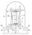
图1为本发明方法采用的装置的结构示意图。Fig. 1 is the structural representation of the device that the method of the present invention adopts.
图2为本发明的系统测试原理图。Fig. 2 is a schematic diagram of the system test of the present invention.
图3为本发明中标准热流量计1的温度传感器布置示意图。Fig. 3 is a schematic diagram of the arrangement of temperature sensors of the standard
图4为采用本发明方法测试一种石墨垫片热界面材料的接触热阻随加热功率的关系。Fig. 4 is the relationship between the contact thermal resistance and the heating power of a graphite gasket thermal interface material tested by the method of the present invention.
具体实施方式Detailed ways
本发明在美国国家标准ASTM D5470基础上提出了一种采用正反双向热流的对称测试结构可以基本消除由于测试热流量计上布置的多个温度传感器与测试热流量计的接触情况各异从而产生的温度测量的不确定性误差,结合可控温热辐射防辐射屏来及辅助加热措施减小热流损失,并采用一经优化的最小测试热流量来保证测试材料的温度梯度的一维性,来达到高精度测试热流量计的热物性参数的目的,本方法可高精度的测量热界面材料的接触热阻性能和有效当量导热系数。Based on the American National Standard ASTM D5470, the present invention proposes a symmetrical test structure using forward and reverse bidirectional heat flow, which can basically eliminate the occurrence of different contact conditions between the multiple temperature sensors arranged on the test heat flow meter and the test heat flow meter. Uncertainty errors in temperature measurement, combined with temperature-controllable thermal radiation shields and auxiliary heating measures to reduce heat flow loss, and using an optimized minimum test heat flow to ensure the one-dimensionality of the temperature gradient of the test material, to To achieve the purpose of testing the thermophysical parameters of the thermal flowmeter with high precision, the method can measure the contact thermal resistance performance and effective equivalent thermal conductivity of the thermal interface material with high precision.
下面结合附图对本发明作进一步详细描述。The present invention will be described in further detail below in conjunction with the accompanying drawings.
在图1中,本发明公开了一种高精度热界面材料的测试装置,该装置为上下正反双向热流测试的对称结构,包括控制系统、支架3、第一滚珠套筒4-1、第二滚珠套筒4-2、滑动螺杆5、定向钢球和压力传感器6、辅助加热器7、真空罩9、试件测试区10、应力加载装置、真空抽放气口13、进出水口14、数据采集系统、密封底盘16,支撑板17,水平调节杆20和加热丝21;其特征在于:应力加载装置由液压缸11和压力动力源12组成,液压缸11位于压力动力源12的上方;数据采集系统由温度传感器、密封数据接头15组成,温度传感器通过导线与密封数据接头15相连;控制系统由可控温防辐射屏2、加热制冷套1和控制防辐射屏加热丝R2组成;试样测试区10包括测试试件,其中定向钢球和压力传感器6、支架3、支撑板17和加热制冷套1上下对称,定向钢球和压力传感器6固定在支撑板17中心位置,应力加载装置通过支架3定位并和定向钢球以及压力传感器6接触,为试样加载应力,第一滚珠套筒4-1设置在滑动螺杆5的上下两端与支撑板17固定,第二滚珠套筒4-2设置在滑动螺杆5的底部并与支架3固定,辅助加热器7位于支撑板17和加热制冷套1之间,试样测试区10位于上下对称的两个加热制冷套1之间,两个可控温防辐射屏2位于试样测试区10的外部,真空罩9位于整个装置的外部固定于密封底盘16上,滑动螺杆5固定于密封底盘16的上部,真空抽放气口13、进出水口14和密封数据接头15均设置在密封底盘16上,液压缸11贯穿密封底盘16的中心,密封底盘上设置有四组水平调节杆20。图2为本发明的测试原理示意图,在进行测试过程中,根据标准材料热流量计上的温度传感器测量温度由控制系统调控防辐射屏上的加热装置和热流量计近似的温度梯度以此来减小热量损失。在上下加热制冷套的位置也相应布置有辅助加热器来调控和加热源近似的温度来减小热损失,为了测量热界面材料的变形量和受压后的竖直轴向的厚度,在两个热流量计的接触界面位置装有原位测量系统。In Fig. 1, the present invention discloses a testing device for high-precision thermal interface materials. Two ball sleeves 4-2, sliding screw 5, directional steel ball and pressure sensor 6, auxiliary heater 7, vacuum cover 9, test piece test area 10, stress loading device, vacuum exhaust port 13, water inlet and outlet 14, data Acquisition system, sealed chassis 16, support plate 17, horizontal adjustment rod 20 and heating wire 21; it is characterized in that: stress loading device is made up of hydraulic cylinder 11 and pressure power source 12, and hydraulic cylinder 11 is positioned at the top of pressure power source 12; Data The acquisition system is composed of a temperature sensor and a sealed data joint 15, and the temperature sensor is connected to the sealed data joint 15 through a wire; the control system is composed of a temperature-controllable radiation protection screen 2, a heating and cooling jacket 1, and a heating wire R2 for controlling the radiation protection screen; The test area 10 includes a test piece, wherein the directional steel ball and the pressure sensor 6, the support 3, the support plate 17 and the heating and cooling jacket 1 are symmetrical up and down, the directional steel ball and the pressure sensor 6 are fixed at the center of the support plate 17, and the stress loading device passes through The bracket 3 is positioned and in contact with the directional steel ball and the pressure sensor 6 to apply stress to the sample. The first ball sleeve 4-1 is arranged at the upper and lower ends of the
在图3中,本发明中插装有温度传感器的标准热流量计1的主视图,在该热流量计上插装有位置上下对称度有严格要求的4组温度传感器。标准热流量计可加工成圆柱体或者长方体,温度传感器的插装孔有严格的位置精度和形状精度要求并保证有足够的上下对称度,在插装温度传感器前对标准热流量计(本案例选用的是Elkonite copper-tungsten alloy30W3材料,导热系数为216±2W/m K,硬度为276HV)进行酒精、丙酮、异丙酮和超声波清洗。温度传感器为对称等距排列,温度传感器的探头是通过焊接或导热膏粘结插装孔里。本实施例温度传感器采用热电阻。In FIG. 3 , the front view of the standard
图4为采用本发明方法测试的一种石墨垫片热界面材料的测试数据。Fig. 4 is the test data of a graphite gasket thermal interface material tested by the method of the present invention.
本发明公开了一种高精度热物性测试方法的测试步骤如下:The invention discloses a high-precision thermal physical property testing method. The testing steps are as follows:
第一步,测试标准材料热流量计的准备。In the first step, the preparation of the test standard material heat flow meter.
如图1和图2所示,上下热流量计之所以选择30W3钨铜合金考虑到以下原因:由于铜的良好的导热性能和钨的高强度使之在材料硬度和导热性能之间达到很好的平衡,所以可在长时间的使用过程中减小破坏接触端面表面形貌的可能性。制作出两标准材料(Elkonite copper-tungsten alloy30W3材料)热流量计,加工出两钨铜合金材料热流量计,将热流量计竖直安装在两个上下对称设置的加热制冷套之间,在两加热制冷套上设置有应力加载装置,所述的热流量计上设置有温度传感器,温度传感器与数据采集系统连接,用于测试热流量计的轴向温度,若所采用的温度传感器为热电偶,则根据该热流量计轴向截面均匀布置的1-4个热电偶平均来求得该轴向点的温度;若所采用的温度传感器为热电阻,则对热流量计轴向截面均匀布置测温的1-4个热电阻采用4线制接法,对该均匀布置的1-4个热电阻的激励电流相同,对该均匀布置的1-4个热电阻信号采集端的引线可采用并联接法来平均求得该轴向点的温度并减小因热电阻的引线造成的热流损失。As shown in Figure 1 and Figure 2, the reason why the upper and lower heat flowmeters choose 30W3 tungsten-copper alloy takes into account the following reasons: due to the good thermal conductivity of copper and the high strength of tungsten, it achieves a good balance between material hardness and thermal conductivity Balance, so the possibility of damaging the surface morphology of the contact end surface can be reduced during long-term use. Two standard materials (Elkonite copper-tungsten alloy30W3 material) heat flowmeters were produced, two tungsten copper alloy heat flowmeters were processed, and the heat flowmeters were installed vertically between two heating and cooling jackets arranged symmetrically up and down. The heating and cooling jacket is provided with a stress loading device, and the heat flowmeter is provided with a temperature sensor connected to the data acquisition system for testing the axial temperature of the heat flowmeter. If the temperature sensor used is a thermocouple , then the temperature of the axial point is obtained based on the average of 1-4 thermocouples uniformly arranged in the axial section of the heat flowmeter; if the temperature sensor used is a thermal resistance, the axial section of the heat flowmeter The 1-4 thermal resistances for temperature measurement adopt the 4-wire connection method, the excitation current of the uniformly arranged 1-4 thermal resistances is the same, and the lead wires of the uniformly arranged 1-4 thermal resistance signal acquisition terminals can be connected in parallel The connection method is used to obtain the average temperature of the axial point and reduce the heat flow loss caused by the lead wire of the thermal resistance.
热流量计上测试点之间的位置满足如下关系:以两热流量计纵轴方向上的接触界面截面位置为对称面,两热流量计上的测试点位置完全对称,每个热流量计从下端面到上端面之间均设置4个测试点,每个热流量计上相邻两个测试点之间的轴向距离相等,测试点之间的距离为dx=25mm,从接触界面到一个测试点的位置为2mm,如图2所示热流量计1的(T.x)4测试点到接触界面的距离为2mm,热流量计2同样从接触界面到一个测试点的位置为2mm。并按温度传感器尺寸在标准材料热流量计和热流量计上等距的加工出温度传感器的探头安装孔,所述的温度传感器的探头安装孔≤0.5mm,探头安装孔里通过焊接或导热膏粘结≤0.5mm的温度传感器探头,温度传感器通过真空腔壁的连接器与数据采集系统连接,本发明的温度传感器采用四线制热电阻。The positions of the test points on the heat flowmeters satisfy the following relationship: taking the cross-sectional position of the contact interface in the direction of the longitudinal axis of the two heat flowmeters as the symmetry plane, the positions of the test points on the two heat flowmeters are completely symmetrical, and each heat flowmeter starts from 4 test points are set between the lower end surface and the upper end surface, the axial distance between two adjacent test points on each heat flowmeter is equal, the distance between the test points is dx=25mm, from the contact interface to a The position of the test point is 2mm, as shown in Figure 2, the distance from the (Tx)4 test point of the
第二步,两热流量计接触界面之间放置热界面材料,加载压应力,正向对热流量计加热:In the second step, a thermal interface material is placed between the contact interfaces of the two thermal flowmeters, the compressive stress is applied, and the thermal flowmeter is heated in a positive direction:
如图1所示将布置有4组温度传感器的热流量计竖直夹装在类似ASTM D5470上下两端对称设有热流量计、加热制冷套、辅助加热装置的真空腔中,为减小热流损失在保温层外层加设一内嵌有加热装置的可控温防辐射屏,在抽真空后进行顶端加热底端制冷的正向热流测试,此时可控温防辐射屏模拟出近似热流量计的温度梯度,顶端布置的辅助加热器根据加热制冷套的温度控制其温度以减小纵轴向的热损失,达到稳态时进行温度数据采集,此时加载热流量可通过上下对称布置的热流量计来换算得到。As shown in Figure 1, the thermal flowmeter with 4 sets of temperature sensors is vertically clamped in a vacuum chamber similar to ASTM D5470, which is symmetrically equipped with thermal flowmeters, heating and cooling jackets, and auxiliary heating devices at the upper and lower ends, in order to reduce the heat flow. Loss A temperature-controllable radiation-proof screen with a built-in heating device is added to the outer layer of the insulation layer. After vacuuming, the positive heat flow test of top heating and bottom-side cooling is carried out. At this time, the temperature-controllable radiation screen simulates an approximate thermal The temperature gradient of the flowmeter, the auxiliary heater arranged at the top controls its temperature according to the temperature of the heating and cooling jacket to reduce the heat loss in the longitudinal axis, and collects temperature data when it reaches a steady state. At this time, the loading heat flow can be arranged symmetrically up and down The heat flow meter is converted to get.
第三步,采集测试点温度和正向接触热阻R′的计算:The third step is to collect the calculation of the test point temperature and the forward contact thermal resistance R':
在加正向热流测试时,如图2所示,根据热流量计1上的(T.x)1、(T.x)2、(T.x)3与(T.x)4和4个测试点位置的温度梯度关系,以及热流量计2上的(T.x)5、(T.x)6、(T.x)7和(T.x)8与4个测试点位置的温度梯度关系,通过数值方法外推得到的热流量计1的外推界面温度为Ts-1′,热流量计2的外推界面温度为Ts-2′。When adding positive heat flow test, as shown in Figure 2, according to (Tx)1 , (Tx)2 , (Tx)3 and (Tx)4 on the
Ts-1′=as-1(Ts-1-T0)+Es-1Ts-1 ′=as-1 (Ts-1 -T0 )+Es-1
Ts-2′=as-2(Ts-2-T0)+Es-2Ts-2 ′=as-2 (Ts-2 -T0 )+Es-2
两热流量计的界面温差为:ΔTs′=Ts-1′-Ts-2′The interface temperature difference between the two heat flowmeters is: ΔTs ′=Ts-1 ′-Ts-2 ′
其中as-1和as-2为温度传感器的系数,Ts-1和Ts-2为两热流量计正向测试时在接触界面的真实温度,T0为热电阻温度传感器的参考温度273.15K,Es-1和Es-2为温度传感器的误差项。Among them, as-1 and as-2 are the coefficients of the temperature sensor, Ts-1 and Ts-2 are the real temperature at the contact interface when the two thermal flowmeters are tested forward, and T0 is the reference of the thermal resistance temperature sensor The temperature is 273.15K, Es-1 and Es-2 are the error terms of the temperature sensor.
则正向接触热阻R′为:Then the forward contact thermal resistance R' is:
其中Q为热流量。where Q is the heat flux.
如图4所示,正向分别加载从1W~9.5W不等的13组热流量,热流量计温度达到稳定后开始采集测试温度;As shown in Figure 4, 13 groups of heat flow ranging from 1W to 9.5W are respectively loaded in the forward direction, and the test temperature is collected after the temperature of the heat flowmeter reaches stability;
第四步,加载压应力,反向加载热流,采集测试点温度:The fourth step is to load the compressive stress, reversely load the heat flow, and collect the temperature of the test point:
同样条件下,维持加载和第二步相同的压应力,反向操作,进行顶端制冷底端加热的反向热流测试,同样此时可控温防辐射屏模拟出近似热流量计的温度梯度,底端布置的辅助加热器根据加热制冷套的温度控制其温度以减小纵轴向的热损失,在达到稳态时再采集该温度数据。Under the same conditions, maintain the same compressive stress as in the second step, reverse the operation, and conduct the reverse heat flow test of cooling at the top and heating at the bottom. At this time, the temperature-controllable radiation shield simulates a temperature gradient similar to that of a heat flow meter. The temperature of the auxiliary heater arranged at the bottom is controlled according to the temperature of the heating and cooling jacket to reduce the heat loss in the longitudinal axis, and the temperature data is collected when the steady state is reached.
第五步,反向接触热阻R″的计算:The fifth step, the calculation of the reverse contact thermal resistance R″:
同样根据热流量计1和热流量计2上的3个测试点的位置和测量温度的温度梯度关系,通过数值方法外推得到的反向测试时热流量计1的接触界面的外推温度Ts-1″和热流量计2的接触界面的外推温度Ts-2″:Also according to the temperature gradient relationship between the positions of the three test points on the
其中,


同理反向接触热阻R″为:Similarly, the reverse contact thermal resistance R″ is:
如图4所示,反向分别加载和第三步同样的从1W~9.5W不等的13组热流量,热流量计温度达到稳定后开始采集测试温度;As shown in Figure 4, reversely load the same 13 groups of heat flow ranging from 1W to 9.5W as in the third step, and start collecting the test temperature after the temperature of the heat flowmeter reaches stability;
第六步,接触热阻R的计算:The sixth step, the calculation of contact thermal resistance R:
因温度传感器的系数as-1=as-2=1,则热界面材料的接触热阻R为:Since the coefficient as-1 =as-2 =1 of the temperature sensor, the thermal contact resistance R of the thermal interface material is:
此时可令
图4为在压力2MPa时正反向加载热流量时的测试接触热阻R′和R″同加载热流量的关系,如图4所示,因在加热功率小于2W时,此时由于温度场的一维性较差热损失也较大,而在热流量大于2W时此时温度场的一维性较好,且热损失也≤0.3%,所以采信热流量3~9.5W时的数据,正向加热测试时接触热阻R′平均约为0.330±0.003K/W,反向加热测试时接触热阻R″约为0.305±0.005K/W,可见由于测试热流量计上布置的多个温度传感器与测试热流量计的接触情况各异从而产生的温度测量的不确定性误差造成正方向测试时偏差达7.8%,因此其造成的误差不能被忽略,继而本方法认为实际接触热阻为
第七步,热界面材料厚度L测量,热界面材料的当量导热系数的计算;The seventh step is to measure the thickness L of the thermal interface material and calculate the equivalent thermal conductivity of the thermal interface material;
如图2所示,通过在两热流量计接触界面位置布置的原位测量系统的参考点位置变化测得热界面材料的厚度L=0.15mm,计算表观接触热阻RA为:RA=A×R=155.607mm2K/W,其中接触面积为A=490.874mm2,从而当量有效导热系数keff为:As shown in Figure 2, the thickness of the thermal interface material L=0.15mm is measured by the position change of the reference point of the in-situ measurement system arranged at the contact interface of the two heat flowmeters, and the apparent contact thermal resistance RA is calculated as: RA =A×R=155.607mm2 K/W, where the contact area is A=490.874mm2 , so the equivalent effective thermal conductivity keff is:
Claims (6)
Translated fromChinese


Priority Applications (1)
| Application Number | Priority Date | Filing Date | Title |
|---|---|---|---|
| CN201210280027.1ACN102768225B (en) | 2012-08-07 | 2012-08-07 | High-accuracy method for testing thermal interface material |
Applications Claiming Priority (1)
| Application Number | Priority Date | Filing Date | Title |
|---|---|---|---|
| CN201210280027.1ACN102768225B (en) | 2012-08-07 | 2012-08-07 | High-accuracy method for testing thermal interface material |
Publications (2)
| Publication Number | Publication Date |
|---|---|
| CN102768225A CN102768225A (en) | 2012-11-07 |
| CN102768225Btrue CN102768225B (en) | 2014-04-02 |
Family
ID=47095698
Family Applications (1)
| Application Number | Title | Priority Date | Filing Date |
|---|---|---|---|
| CN201210280027.1AActiveCN102768225B (en) | 2012-08-07 | 2012-08-07 | High-accuracy method for testing thermal interface material |
Country Status (1)
| Country | Link |
|---|---|
| CN (1) | CN102768225B (en) |
Cited By (1)
| Publication number | Priority date | Publication date | Assignee | Title |
|---|---|---|---|---|
| US10600699B2 (en)* | 2017-08-24 | 2020-03-24 | Intel Corporation | Apparatus for inspection of a package assembly with a thermal solution |
Families Citing this family (13)
| Publication number | Priority date | Publication date | Assignee | Title |
|---|---|---|---|---|
| CN102980910B (en)* | 2012-11-30 | 2014-11-05 | 深圳市博恩实业有限公司 | Heat conduction material performance test equipment |
| CN103364101B (en)* | 2013-07-08 | 2015-02-25 | 中国电子科技集团公司第十一研究所 | Thermal interface uniformity detecting system and method |
| CN104950009B (en)* | 2014-03-28 | 2018-11-20 | 杭州远方光电信息股份有限公司 | A kind of thermal resistance analysis method |
| CN104181193B (en)* | 2014-08-23 | 2017-05-17 | 华北电力大学(保定) | Method for calculating thermal resistance of packing layer in compound optical fiber of three-core submarine cable |
| CN105628503A (en)* | 2014-11-05 | 2016-06-01 | 桂林电子科技大学 | Sustained and stable high-precision vacuum pressure loading device |
| CN104535609B (en)* | 2014-12-26 | 2018-03-09 | 怡维怡橡胶研究院有限公司 | A kind of heat conducting coefficient measurement device |
| CN104569045B (en)* | 2015-01-14 | 2017-06-06 | 北京工业大学 | Faying face thermal contact resistance method of testing and device between cylindrical sleeve barrel |
| CN105372288B (en)* | 2015-10-28 | 2018-02-13 | 中国农业大学 | A kind of rate of heat flow measuring instrument and measuring method |
| CN107966472B (en)* | 2017-12-05 | 2020-08-14 | 中国空气动力研究与发展中心计算空气动力研究所 | Nondestructive rapid measurement method for high-temperature contact thermal resistance |
| CN108445040B (en)* | 2018-03-05 | 2021-06-15 | 大连海事大学 | A contact thermal resistance test method with thermal expansion correction |
| CN115218994B (en)* | 2021-04-21 | 2025-01-28 | 中国石油天然气股份有限公司 | Natural gas flow meter testing device and method |
| CN113514492B (en)* | 2021-06-02 | 2023-09-01 | 中国电子产品可靠性与环境试验研究所((工业和信息化部电子第五研究所)(中国赛宝实验室)) | Method and device for measuring interface thermal resistance |
| CN117129523A (en)* | 2023-08-29 | 2023-11-28 | 北京市计量检测科学研究院 | Device and method for testing temperature of heat dissipation coating of integrated circuit |
Citations (3)
| Publication number | Priority date | Publication date | Assignee | Title |
|---|---|---|---|---|
| US5940784A (en)* | 1996-03-08 | 1999-08-17 | Metrisa, Inc. | Heat flow meter instruments |
| CN101929970A (en)* | 2010-07-13 | 2010-12-29 | 北京航空航天大学 | Contact thermal resistance test method and test equipment |
| CN102297877A (en)* | 2011-05-27 | 2011-12-28 | 上海大学 | Device and method for measuring thermoelectric parameters of film |
Family Cites Families (2)
| Publication number | Priority date | Publication date | Assignee | Title |
|---|---|---|---|---|
| JP3858660B2 (en)* | 2001-10-10 | 2006-12-20 | 株式会社日立製作所 | Measuring method of thermal resistance of resin |
| US6923570B2 (en)* | 2003-09-11 | 2005-08-02 | Hewlett-Packard Development Company, L.P. | Thermal interface material characterizing system |
- 2012
- 2012-08-07CNCN201210280027.1Apatent/CN102768225B/enactiveActive
Patent Citations (3)
| Publication number | Priority date | Publication date | Assignee | Title |
|---|---|---|---|---|
| US5940784A (en)* | 1996-03-08 | 1999-08-17 | Metrisa, Inc. | Heat flow meter instruments |
| CN101929970A (en)* | 2010-07-13 | 2010-12-29 | 北京航空航天大学 | Contact thermal resistance test method and test equipment |
| CN102297877A (en)* | 2011-05-27 | 2011-12-28 | 上海大学 | Device and method for measuring thermoelectric parameters of film |
Non-Patent Citations (2)
| Title |
|---|
| 张平 等.界面接触热阻的研究进展.《化工学报》.2012,第63卷(第2期),335-349页. |
| 界面接触热阻的研究进展;张平 等;《化工学报》;20120229;第63卷(第2期);335-349页* |
Cited By (1)
| Publication number | Priority date | Publication date | Assignee | Title |
|---|---|---|---|---|
| US10600699B2 (en)* | 2017-08-24 | 2020-03-24 | Intel Corporation | Apparatus for inspection of a package assembly with a thermal solution |
Also Published As
| Publication number | Publication date |
|---|---|
| CN102768225A (en) | 2012-11-07 |
Similar Documents
| Publication | Publication Date | Title |
|---|---|---|
| CN102768225B (en) | High-accuracy method for testing thermal interface material | |
| CN102768224B (en) | Testing method for testing solid-solid contact thermal resistance by using forward and reverse bidirectional heat flux method | |
| CN102798645B (en) | Heat conduction coefficient and contact thermal resistance testing device | |
| CN102830134B (en) | Up-and-down constant-temperature parameter identifying method for testing thermal interface material performance | |
| CN102297877B (en) | Device and method for measuring thermoelectric parameters of film | |
| CN104181195B (en) | Steady-state method-based heat conductivity coefficient measurement device | |
| CN101290299B (en) | Variable thermal conductivity factor measuring apparatus and method | |
| Zhang et al. | A high-precision instrumentation of measuring thermal contact resistance using reversible heat flux | |
| CN101126729B (en) | Measuring method of thermal conductivity of materials by double heat flow meter steady state method | |
| CN106653117A (en) | Visual experiment system for measuring temperature field of rod bundle channel | |
| CN102778475B (en) | Method for measuring solid-solid thermal contact resistance via up-and-down constant temperature parameter identification method | |
| Taler et al. | Thermal stress monitoring in thick walled pressure components of steam boilers | |
| CN104034749A (en) | Method for testing contact thermal resistance among thin-layer materials based on 3-omega method | |
| CN106017298A (en) | Direct contact type stretching deformation measuring system and method in high-temperature oxygen-free environment | |
| CN103713010A (en) | Quick-release testing device and method for measuring heat transfer process under condition of high heat flux density | |
| CN202171579U (en) | Double test piece protection hot plate method heat conducting instrument | |
| CN112229871A (en) | Thermal contact resistance testing device and method | |
| CN102590274B (en) | System and method used for testing heat conductivity of thin film thermoelectric material | |
| CN115031922B (en) | A pressure-bearing three-sided visual thermal fluid experiment section with heating components | |
| CN104267070B (en) | A kind of device measuring liquid thermal conductivity factor based on Adsorbent By Using Transient Plane Source Technique | |
| CN109324079B (en) | A method for measuring the thermal expansion coefficient of materials based on ultrasound | |
| CN114593835A (en) | Temperature acquisition component and method for measuring surface heat flux density of flat plate specimens in arc wind tunnel | |
| CN105973929A (en) | Non-destructive testing method for detecting thermal contact resistance inside parts by infrared camera | |
| CN104749214B (en) | A kind of constant temperature hot bath device that liquid thermal conductivity factor is measured based on Adsorbent By Using Transient Plane Source Technique | |
| CN111157574B (en) | Experimental device for contact thermal resistance measurement |
Legal Events
| Date | Code | Title | Description |
|---|---|---|---|
| C06 | Publication | ||
| PB01 | Publication | ||
| C10 | Entry into substantive examination | ||
| SE01 | Entry into force of request for substantive examination | ||
| C14 | Grant of patent or utility model | ||
| GR01 | Patent grant |