CN102765087A - Modular self-reconfigurable robot and method for controlling deformation thereof - Google Patents
Modular self-reconfigurable robot and method for controlling deformation thereofDownload PDFInfo
- Publication number
- CN102765087A CN102765087ACN201210270345XACN201210270345ACN102765087ACN 102765087 ACN102765087 ACN 102765087ACN 201210270345X ACN201210270345X ACN 201210270345XACN 201210270345 ACN201210270345 ACN 201210270345ACN 102765087 ACN102765087 ACN 102765087A
- Authority
- CN
- China
- Prior art keywords
- module
- configuration
- butt joint
- joint
- head
- Prior art date
- Legal status (The legal status is an assumption and is not a legal conclusion. Google has not performed a legal analysis and makes no representation as to the accuracy of the status listed.)
- Granted
Links
Images


Landscapes
- Manipulator (AREA)
Abstract
Translated fromChinese
Description
Translated fromChinese技术领域technical field
本发明属于机器人技术领域,涉及机器人的重构变形,为一种模块化自重构机器人及其变形控制方法。The invention belongs to the technical field of robots, relates to the reconfiguration and deformation of a robot, and relates to a modular self-reconfiguration robot and a deformation control method thereof.
背景技术Background technique
模块化自重构机器人由若干具有一定自治能力和感知能力的单元模块组成。各模块具备统一机械和电气接口,可自主对接组装为各种联体构型并可相互转换,从而实现不同的运动和操作功能。模块化自重构机器人的主要特点是自重构功能和自修复功能,要求模块化自重构求机器人能够根据环境、任务的变化,在不同的构型之间实现转换,从而能有效的完成一些更加复杂的、高难度的任务。“一”构型应用于爬行狭长的通道或者是跨越沟壑,当地面环境比较崎岖的时候,我们需要将“一”构型变换为“十”构型,运用仿生形的步态控制,跨越障碍物。为了适应复杂的环境和满足多变的任务,在不同构型之间实现变换的控制方法成为模块化自重构机器人研究中重要问题之一。Modular self-reconfigurable robots are composed of several unit modules with certain autonomy and perception capabilities. Each module has a unified mechanical and electrical interface, and can be independently docked and assembled into various conjoined configurations and can be converted to each other, so as to realize different motion and operation functions. The main characteristics of modular self-reconfigurable robots are self-reconfiguration and self-repair functions. Modular self-reconfiguration requires that the robot can switch between different configurations according to changes in the environment and tasks, so that it can effectively complete Some more complicated and difficult tasks. The "one" configuration is used for crawling narrow and long passages or crossing ravines. When the ground environment is relatively rough, we need to change the "one" configuration to the "ten" configuration, using bionic gait control to cross obstacles thing. In order to adapt to the complex environment and meet the changing tasks, the control method to realize the transformation between different configurations has become one of the important issues in the research of modular self-reconfigurable robots.
日本AIST机械工程实验室研制的M-TRAN模块化自重构机器人,基本模块由两个半圆柱体和连接杆组成,机器人的变形是基于模块的两个半圆柱体在空间内相对翻转实现的,对于控制方法的定位精度要求较高,因此变形的局限性很大。PaloAlto研究中心设计的PolyBot自重构机器人,它属于链式结构的自重构机器人,机器人变形过程中是利用SMA形状记忆合金实现对接,SMA形状记忆合金耗电多,机器人结构的计算分析和控制较困难,实现大面积的自重构任务的难度和代价较大。The M-TRAN modular self-reconfigurable robot developed by the Japanese AIST Mechanical Engineering Laboratory, the basic module is composed of two half-cylinders and connecting rods, and the deformation of the robot is realized based on the relative flipping of the two half-cylinders in space. , the positioning accuracy of the control method is high, so the deformation is very limited. The PolyBot self-reconfigurable robot designed by the PaloAlto Research Center is a self-reconfigurable robot with a chain structure. During the deformation process of the robot, SMA shape memory alloy is used to achieve docking. SMA shape memory alloy consumes a lot of power, and the calculation analysis and control of the robot structure It is more difficult, and it is more difficult and costly to realize a large-scale self-reconfiguration task.
发明内容Contents of the invention
针对现有方法的不足,本发明提供一种模块化自重构机器人“一”构型和“十”构型的变形控制方法。能简单有效的实现单体之间的分离、自动对接,完成由“一”构型和“十”构型的变形,最终能处理更加复杂的、高难度的任务。Aiming at the deficiencies of the existing methods, the present invention provides a deformation control method for the "one" configuration and the "ten" configuration of a modular self-reconfigurable robot. It can easily and effectively realize the separation and automatic docking of monomers, complete the transformation from "one" configuration and "ten" configuration, and finally can handle more complex and difficult tasks.
本发明的技术方案为:一种模块化自重构机器人,由至少三个单体连接构成,实现“一”构型和“十”构型,所述单体由前、中、后三个关节依次连接组成,所述关节包括两个U形框和舵机,所述U形框由一个底面和两个连接臂组成,连接臂对称设置在底面的两侧;两个U形框的连接臂上设有铰接孔,两个U形框通过铰接孔铰接在一起,转动连接,舵机固定在其中一个U形框内,驱动另一个U形框转动;前、中、后三个关节之间通过U形框的底面相互固定连接,所述单体放置在水平面上时,前关节和后关节俯仰转动,中关节左右转动;The technical solution of the present invention is: a modular self-reconfigurable robot, which is composed of at least three monomers connected to realize a "one" configuration and a "ten" configuration. The monomers are composed of front, middle and rear three The joints are connected sequentially, the joints include two U-shaped frames and steering gear, the U-shaped frame is composed of a bottom surface and two connecting arms, and the connecting arms are symmetrically arranged on both sides of the bottom surface; the connection of the two U-shaped frames There are hinge holes on the arm, and the two U-shaped frames are hinged together through the hinge holes and are connected by rotation. The steering gear is fixed in one of the U-shaped frames and drives the other U-shaped frame to rotate; the three joints of the front, middle and rear The joints are fixedly connected to each other through the bottom surface of the U-shaped frame. When the monomer is placed on a horizontal plane, the front joint and the rear joint will pitch and rotate, and the middle joint will rotate left and right;
所述单体连接构型,“一”构型时,各单体前后关节相连成直链,单体之间相互连接的U形框底面上分别设有对接锥头和卡接孔,底面中间设有对接锥头的U形框称为对接公头,底面中间设有卡接孔的U形框称为对接母头,所述对接锥头与卡接孔构成卡接结构,对接公头的底面中间设有圆孔,对接锥头穿过所述圆孔连接一旋转齿轮,对接公头的底面上还设有直流电机,所述直流电机的输出轴驱动旋转齿轮,带动对接锥头旋转,对接锥头侧面设有卡齿,卡接孔直径与对接锥头一致,设有对应所述卡齿的卡槽,对接公头与对接母头连接时,对接锥头对应卡槽位置穿过卡接孔,旋转后,卡齿卡在卡接孔未设卡槽的边缘,实现卡接;The connection configuration of the monomers, in the "one" configuration, the front and rear joints of each monomer are connected to form a straight chain, and the bottom surface of the U-shaped frame connected to each other between the monomers is respectively provided with a butt taper and a snap-in hole, and the middle of the bottom surface The U-shaped frame with the butt joint head is called the butt male head, and the U-shaped frame with the clamping hole in the middle of the bottom surface is called the butt joint female head. The butt joint cone head and the clamping hole form a clamping structure. There is a round hole in the middle of the bottom surface, the docking cone head passes through the round hole to connect a rotating gear, and a DC motor is also provided on the bottom surface of the docking male head, the output shaft of the DC motor drives the rotating gear, driving the docking cone head to rotate, The side of the docking cone head is provided with locking teeth, the diameter of the locking hole is the same as that of the docking cone head, and there is a slot corresponding to the locking teeth. After the connection hole is rotated, the teeth are stuck on the edge of the connection hole without a slot to realize the connection;
“十”构型时,将“一”构型中的单体分为首模块、中间模块和尾模块三个部分,十字交叉点位于中间模块,中间模块在所述十字交叉点位置的两侧设有连接面,连接面上设有卡接孔,首模块和尾模块通过连接锥头连接至所述连接面的卡接孔,得到“十”构型;其中,首模块和尾模块与连接面连接的U形框底面上设有一对红外接收管,连接面上设有一对红外发射管。In the "ten" configuration, the monomer in the "one" configuration is divided into three parts: the first module, the middle module and the tail module, the cross point is located in the middle module, and the middle module is set on both sides of the cross point There is a connection surface, on which there are clamping holes, and the head module and the tail module are connected to the clamping holes on the connection surface through the connecting cone to obtain a "ten" configuration; wherein, the first module and the tail module are connected to the connection surface A pair of infrared receiving tubes are arranged on the bottom surface of the connected U-shaped frame, and a pair of infrared emitting tubes are arranged on the connecting surface.
上述模块化自重构机器人的变形控制方法,由上位机控制将“一”构型变形为“十”构型,将“一”构型分为首模块、中间模块和尾模块三部分,每个模块包括至少一个单体,十字交叉点位于中间模块,“一”构型时,中间模块的两端为对接母头,首、尾模块通过对接公头连接中间模块,“一”构型变形为“十”构型时,所述三部分模块分解:待分解处的对接公头的直流电机旋转带动对接锥头旋转,对应卡接孔的卡槽位置,首、尾模块分别向远离中间模块的方向直线移动,使首、尾模块和中间模块实现完全分离,所述直线移动通过单体前关节与后关节的俯仰转动动作,利用关节与地面的摩擦力,波浪式直线移动;然后中间模块通过单体的中关节左右转动,利用前、后关节与地面的摩擦力,调整角度旋转90°,和首、尾模块成垂直状态,首、尾模块再向着中间模块的方向直线移动,根据首尾模块对接公头上的红外接收管,以及中间模块对接面上的红外发射管,通过红外强度与距离的关系建立数学模型,通过红外接收管接收的红外强度值推算出对接公头与对接面的距离,当对接公头距对接面距离达到设定的对接距离阈值,自动对接过程开始:The deformation control method of the above modular self-reconfigurable robot is controlled by the host computer to transform the "one" configuration into the "ten" configuration, and divide the "one" configuration into three parts: the first module, the middle module and the tail module. The module includes at least one single body, and the cross point is located in the middle module. In the "one" configuration, the two ends of the middle module are docking females, and the head and tail modules are connected to the middle module through the docking males. The "one" configuration is deformed as In the "ten" configuration, the three parts of the modules are disassembled: the DC motor of the docking male head at the position to be disassembled rotates to drive the docking cone to rotate, corresponding to the slot position of the clamping hole, and the head and tail modules are respectively moved away from the middle module. Move in a straight line in the direction, so that the head and tail modules and the middle module are completely separated. The straight-line movement passes through the pitching and turning action of the front joint and the rear joint of the single body, and uses the friction between the joint and the ground to move in a wave-like manner; then the middle module passes through The middle joint of the monomer rotates left and right, using the friction between the front and rear joints and the ground, adjusts the angle to rotate 90°, and is perpendicular to the head and tail modules. The infrared receiving tube on the docking male head and the infrared emitting tube on the docking surface of the intermediate module establish a mathematical model through the relationship between infrared intensity and distance, and calculate the distance between the docking male head and the docking surface through the infrared intensity value received by the infrared receiving tube , when the distance between the docking male head and the docking surface reaches the set docking distance threshold, the automatic docking process starts:
1)首、尾模块的对接公头向左右15°范围内按5°递增模式进行角度搜索,寻找对接面红外发射管发射红外强度最大的方向,完成对接面初始相对角度调整;1) The docking male heads of the head and tail modules conduct an angle search in a 5° increment mode within 15° to the left and right, and find the direction where the infrared emission tube of the docking surface emits the largest infrared intensity, and complete the initial relative angle adjustment of the docking surface;
2)在所述红外强度最大的方向上测量首、尾模块的红外接收管和中间模块对接面的红外发射管的距离值,上传至上位机,上位机根据已知的红外发射管与对接面卡接孔位置关系、红外接收管与对接锥头位置关系、以及所述距离值建立一个局部坐标系,计算对接公头和对接面相对角度偏差和相对位移偏差,首、尾模块根据得到的偏差值调整与中间模块的相对位置;2) Measure the distance between the infrared receiving tubes of the head and tail modules and the infrared emitting tube on the docking surface of the middle module in the direction of the maximum infrared intensity, and upload it to the host computer. The positional relationship between the clamping hole, the positional relationship between the infrared receiving tube and the docking cone, and the distance value establish a local coordinate system to calculate the relative angle deviation and relative displacement deviation between the docking male head and the docking surface, and the head and tail modules are based on the obtained deviation. Value adjustment relative to the middle module;
循环以上两个步骤,直到对接公头与对接面完全正对,且距离足以完成对接锥头与卡接孔的卡接,首、尾模块驱动对接锥头,同时进行与对接面的对接,实现由“一”构型到“十”构型的变形。Repeat the above two steps until the docking male head and the docking surface are completely facing each other, and the distance is enough to complete the clamping of the docking cone and the clamping hole, the head and tail modules drive the docking cone, and at the same time dock the docking surface to The deformation from "one" configuration to "ten" configuration.
进一步的,上位机控制机器人由“十”构型变为“一”构型,首模块、中间模块和尾模块三部分完全分离,中间模块旋转90°,和首、尾模块成直链状态,首、尾模块的对接公头通过红外接收管管,以及中间模块对接母头的红外发射管进行自动对接过程,至首、尾模块的对接公头与中间模块的对接母头连接完成,实现由“十”构型到“一”构型的变形。Further, the upper computer controls the robot from the "ten" configuration to the "one" configuration, the three parts of the first module, the middle module and the tail module are completely separated, the middle module rotates 90°, and the head and tail modules are in a straight chain state, The docking males of the head and tail modules go through the infrared receiving tube and the infrared transmitting tube of the intermediate module docking female to carry out automatic docking process, until the docking males of the head and tail modules are connected with the docking females of the middle module, and the realization is realized by The deformation of "ten" configuration to "one" configuration.
所述自动对接开始的对接距离阈值设置为9~11cm。The docking distance threshold for the start of the automatic docking is set to 9-11 cm.
本发明具有以下有益效果:一,可以有效的实现单体之间的对接和分离;二,首尾单模块单体能够和旋转后的双模块单体实现自动对接,完成从“一”型到“十”型的变形;三,控制方法简单可靠。The invention has the following beneficial effects: first, the docking and separation between monomers can be effectively realized; second, the first and last single-module monomers can realize automatic docking with the rotated double-module monomers, and complete the transformation from "one" type to " Ten" type of deformation; three, the control method is simple and reliable.
附图说明Description of drawings
图1是本发明单模块单体的结构图。Fig. 1 is a structural diagram of a single module monomer of the present invention.
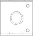
图2是本发明对接公头的上视图。Fig. 2 is a top view of the butt joint of the present invention.
图3是本发明双模块单体的结构图。Fig. 3 is a structural diagram of a double module monomer of the present invention.
图4是本发明对接母头的立体图。Fig. 4 is a perspective view of a docking female head of the present invention.
图5是本发明对接公头对接母头锁紧状态。Fig. 5 is the locking state of the butt male butt female in the present invention.
图6是本发明对接公头对接母头分离状态。Fig. 6 is the separation state of the butt joint butt joint female joint of the present invention.
图7是本发明“一”构型的结构图。Fig. 7 is a structural diagram of the "one" configuration of the present invention.
图8是单模块单体行走一个步长过程图Figure 8 is a step-by-step process diagram of a single module walking
图9是本发明“一”构型到“十”构型的变形过程。Fig. 9 is the deformation process from the "one" configuration to the "ten" configuration of the present invention.
图10是本发明双模块单体旋转90°的立体图。Fig. 10 is a perspective view of the double module unit of the present invention rotated by 90°.
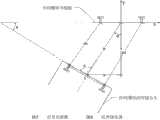
图11是对接过程中建立的局部坐标系。Figure 11 is the local coordinate system established during the docking process.
图12是本发明对接为“十”构型的立体图。Fig. 12 is a perspective view of the present invention docked in a "ten" configuration.
图13是本发明“一”构型到“十”构型的变形流程图。Fig. 13 is a flow chart of the deformation from "one" configuration to "ten" configuration of the present invention.
具体实施方式Detailed ways
下面结合附图和实施例,对本发明作进一步详细说明。The present invention will be described in further detail below in conjunction with the accompanying drawings and embodiments.
本发明为一种模块化自重构机器人,由至少四个单体连接构成,实现“一”构型和“十”构型,如图1所示,本发明的单体由前关节1、后关节2、中关节3三个部分依次连接组成,所述关节包括两个U形框和舵机,所述U形框由一个底面和两个连接臂组成,连接臂对称设置在底面的两侧;两个U形框的连接臂上设有铰接孔,两个U形框通过铰接孔铰接在一起,转动连接,舵机固定在其中一个U形框内,驱动另一个U形框转动;The present invention is a modular self-reconfigurable robot, which is composed of at least four monomers connected to realize "one" configuration and "ten" configuration. As shown in Figure 1, the monomers of the present invention are composed of
所述单体连接构型,“一”构型时,各单体前后关节相连成直链,单体之间相互连接的U形框底面上分别设有对接锥头和卡接孔,底面中间设有对接锥头的U形框称为对接公头,如图2所示,底面中间设有卡接孔的U形框称为对接母头,如图4所示。前、中、后三个关节之间通过U形框的底面相互固定连接,所述单体放置在水平面上时,前关节和后关节俯仰转动,中关节左右转动;各单体之间通过对接锥头与卡接孔连接。The connection configuration of the monomers, in the "one" configuration, the front and rear joints of each monomer are connected to form a straight chain, and the bottom surface of the U-shaped frame connected to each other between the monomers is respectively provided with a butt taper and a snap-in hole, and the middle of the bottom surface A U-shaped frame with a butt taper head is called a butt male head, as shown in Figure 2, and a U-shaped frame with a clamping hole in the middle of the bottom surface is called a butt female head, as shown in Figure 4. The front, middle, and rear joints are fixedly connected to each other through the bottom surface of the U-shaped frame. When the monomer is placed on the horizontal plane, the front joint and the rear joint rotate in pitch and the middle joint rotates left and right; The taper head is connected with the clamping hole.
所述对接锥头与卡接孔构成卡接结构,如图2所示,对接公头101的底面中间设有圆孔,对接锥头102穿过所述圆孔连接一旋转齿轮107,对接公头101的底面上还设有直流电机108,所述直流电机108的输出轴齿轮与旋转齿轮107啮合,驱动齿轮107旋转,进而带动对接锥头102旋转,对接锥头侧面设有卡齿,卡接孔204直径与对接锥头102一致,设有对应所述卡齿的卡槽,如图4;对接公头与对接母头的连接如图5和图6所示,对接锥头对应卡槽位置穿过卡接孔,旋转后,卡齿卡在卡接孔未设卡槽的边缘,实现卡接,图5为锁紧状态,图6为分离状态。The docking cone and the clamping hole form a clamping structure. As shown in Figure 2, a circular hole is provided in the middle of the bottom surface of the
对接公头的底面上设有一对红外接收管104、106,分别通过红外对管安装孔103、105安装在对接公头上,对接母头上也设有一对红外发射管202、206,分别通过红外对管安装孔203、205安装在对接母头上;对接公头和对接母头通过所述红外接收管和红外发射管定位。A pair of
“十”构型时,将“一”构型中的单体分为首模块、中间模块和尾模块三个部分,十字交叉点位于中间模块,中间模块在所述十字交叉点位置的两侧设有连接面,连接面上设有卡接孔,首模块和尾模块通过连接锥头连接至所述连接面的卡接孔,得到“十”构型;其中,首模块和尾模块与连接面连接的U形框底面上设有一对红外接收管,连接面上设有一对红外发射管。In the "ten" configuration, the monomer in the "one" configuration is divided into three parts: the first module, the middle module and the tail module, the cross point is located in the middle module, and the middle module is set on both sides of the cross point There is a connection surface, on which there are clamping holes, and the head module and the tail module are connected to the clamping holes on the connection surface through the connecting cone to obtain a "ten" configuration; wherein, the first module and the tail module are connected to the connection surface A pair of infrared receiving tubes are arranged on the bottom surface of the connected U-shaped frame, and a pair of infrared emitting tubes are arranged on the connecting surface.
下面以四个单体构成的模块化自重构机器人为例来说明本发明的实施。The implementation of the present invention will be described below by taking a modular self-reconfigurable robot composed of four monomers as an example.
如图3所示,中间模块为两个单体组成,J1、J3、J4、J6为双模块单体的四个俯仰关节,J2、J5为其两个旋转关节,卡槽4用于和首、尾模块的单体侧面对接。As shown in Figure 3, the middle module is composed of two modules, J1, J3, J4, and J6 are the four pitch joints of the dual-module monomer, J2 and J5 are the two rotation joints, and the
由“一”构型变形为“十”构型,将“一”构型分为首模块、中间模块和尾模块三部分,每个模块包括至少一个单体,十字交叉点位于中间模块,“一”构型时,中间模块的两端为对接母头,首、尾模块通过对接公头连接中间模块,如图7所示,为实施例的机器人的初始构型“一”构型,由4个单体构成,首尾各一个单体作为“十”构型的首、尾模块,中间的两个单体作为“十”构型的中间模块。The "one" configuration is transformed into the "ten" configuration, and the "one" configuration is divided into three parts: the first module, the middle module and the tail module. Each module includes at least one monomer, and the cross point is located in the middle module. "One" " configuration, the two ends of the middle module are docking females, and the head and tail modules are connected to the middle module through the docking males, as shown in Figure 7, which is the initial configuration "one" configuration of the robot of the embodiment, consisting of 4 The first and last monomers are used as the first and last modules of the "ten" configuration, and the two middle monomers are used as the middle module of the "ten" configuration.
三部分模块的分解为:待分解处的对接公头的直流电机旋转带动对接锥头旋转,对应卡接孔的卡槽位置,首、尾模块分别向远离中间模块的方向直线移动,使首、尾单模块和中间模块实现完全分离,所述直线移动为通过单体前关节与后关节的俯仰转动动作,利用关节与地面的摩擦力,波浪式直线移动。然后中间模块通过单体的中关节左右转动,利用前、后关节与地面的摩擦力,调整角度旋转90°,和首、尾模块成垂直状态,首、尾模块再向着中间模块的方向直线移动,检测到距中间模块单体为10cm左右,自动对接过程开始。The decomposition of the three-part module is as follows: the rotation of the DC motor of the docking male head at the place to be disassembled drives the rotation of the docking cone head, corresponding to the position of the slot of the clamping hole, the head and tail modules move linearly away from the middle module respectively, so that the head, tail The tail single module and the middle module are completely separated. The linear movement is through the pitching and turning action of the front joint and the rear joint of the single body, and the friction between the joint and the ground is used to move linearly in a wave. Then the middle module rotates left and right through the middle joint of the monomer, and uses the friction force between the front and rear joints and the ground to adjust the angle to rotate 90°, and it is perpendicular to the head and tail modules, and then the head and tail modules move in a straight line towards the middle module , it is detected that the distance from the middle module is about 10cm, and the automatic docking process starts.
如图8所示,图中Step1~Step5为单体一个运动周期,Step1为初始状态,节点处于伸展状态,为运动作准备。Step2中,前关节向上偏转θ1角度,为的是减少模块运动过程中与地面的摩擦力。Step3中,后关节向下偏转θ2角度,由于摩擦力的作用,整个单体并没有向前移动而是将向前的驱动力转化成中关节的上拱。Step4中,前关节由原来的向上偏转θ1转变为向下偏转一定的角度,后关节的水平高度高于前关节,这样为单体向前移动提供更加充足的力矩。在Step5中,后关节向上偏转θ2使关节处于伸展状态,由此产生向前驱动力,驱动整个单体向前移动,前关节向上摆动一定的角度,使关节处于伸展状态,恢复Step1状态,开始下一轮的循环。其中S为单体一个运动周期所走的距离即一个步长,在本实施例中为2cm~2.8cm。As shown in Figure 8, Step1~Step5 in the figure is a single movement cycle, Step1 is the initial state, and the nodes are in the stretched state, preparing for movement. In Step2, the front joint is deflected upward by an angle of θ1 in order to reduce the friction between the module and the ground during movement. In Step3, the rear joint is deflected downward by an angle of θ2. Due to the effect of friction, the whole body does not move forward but converts the forward driving force into the upward arch of the middle joint. In Step4, the front joint changes from the original upward deflection θ1 to a certain downward deflection angle, and the level of the rear joint is higher than that of the front joint, which provides more sufficient torque for the monomer to move forward. In Step5, the rear joint is deflected upward by θ2 to make the joint in a stretched state, thereby generating a forward driving force, which drives the entire monomer to move forward, and the front joint swings upwards at a certain angle, making the joint in a stretched state, returning to the state of Step1, and starting The next round of the cycle. Wherein, S is the distance traveled by the monomer in one movement cycle, that is, a step length, which is 2 cm to 2.8 cm in this embodiment.
如图9所示,为“一”构型到“十”构型变形过程中双模块单体实现旋转的具体步态。图中step1到step6为一个运动周期,在step1中,初始构型“一”构型收到上位机变形控制的命令之后,待分解处的对接公头分别控制各自的直流电机108旋转,带动对接锥头102旋转60°,使得待分解处的对接公头101和对接母头201处于分离状态。首、尾模块分别向远离中间模块的方向移动一个步长,首、尾模块和中间模块实现完全分离;在step2中,中间模块的关节J1、J6向下偏转,这样有利于增加整个模块端部与地面的摩擦力;在step3中,中间模块的关节J2、J5分别向右、向左摆动一定的角度,带动中间模块旋转一定的角度,然后关节J1、J6向上偏转一定的角度,关节J1、J6恢复初始的状态;在step4中,关节J3向上旋转一定的角度,关节J2向左摆动一定的角度,J2恢复初始状态,关节J3向下摆动一定角度,关节J1、J2、J3恢复初始状态;Step5的过程正好和step4相对应,关节J4、J5、J6恢复初始状态;在Step6中,整个中间模块整体旋转过约15°并恢复初始状态,为下一次循环作准备。上述步骤中提到的一定角度均上位机通过关节的舵机控制,如表1所示,为中间模块实现旋转的具体步态表。其中A代表关节的俯仰旋转角度,+A代表向上的旋转的角度,-A代表向下旋转的角度,B代表关节的水平方向旋转的角度,+B代表从纸面旋出的角度,-B代表向纸内旋进去的角度。转动角度可以预先对舵机进行设置,例如设置每次旋转15°。As shown in Figure 9, it is the specific gait of the double-module monomer to realize the rotation during the deformation process from the "one" configuration to the "ten" configuration. In the figure, step1 to step6 are a motion cycle. In step1, after the initial configuration "one" configuration receives the deformation control command from the host computer, the docking males at the positions to be disassembled respectively control the rotation of their
表1Table 1

如图10、图11、图12所示,中间模块按照图9所示的旋转周期旋转6次,即旋转90°,和首、尾模块对接公头成垂直状态,最后完成对接。具体的过程为:首先,中间模块按照旋转步态表进行角度调整,直至中间模块和首、尾模块的主动对接面成垂直状态,也就是对接公头垂直于中间模块十字交叉点所处的平面,即对接面;其次,首、尾模块需向着中间模块的方向一段距离,通过红外接收管检测到距中间模块10cm左右,自动对接开始,首、尾模块和中间模块的对接同时进行。首模块的控制对接公头向左右15°范围内按5°递增模式进行角度搜索,寻找中间模块发射红外强度最大的方向,完成对接面初始相对角度调整;如图11所示,在该方向上测量对接公头的一对红外接收管与对接面一对红外发射管的距离值,上传至上位机,上位机根据已知的红外发射管与对接面卡接孔位置关系、红外接收管与对接锥头位置关系、以及所述距离值建立一个局部坐标系,计算对接公头和对接面相对角度偏差和相对位移偏差,首、尾模块根据得到的偏差值调整与中间模块的相对位置;如图11,计算如下:As shown in Figure 10, Figure 11, and Figure 12, the middle module rotates 6 times according to the rotation cycle shown in Figure 9, that is, rotates 90°, and is perpendicular to the docking male head of the head and tail modules, and finally completes the docking. The specific process is as follows: First, the middle module adjusts the angle according to the rotation gait table until the active docking surfaces of the middle module and the head and tail modules are in a vertical state, that is, the docking male head is perpendicular to the plane where the cross point of the middle module is located , that is, the docking surface; secondly, the head and tail modules need to face a certain distance in the direction of the middle module, and the infrared receiving tube detects that the distance from the middle module is about 10cm, and the automatic docking starts, and the docking of the head, tail modules and the middle module is carried out at the same time. The control docking male head of the first module conducts an angle search within 15° to the left and right in a 5° increment mode to find the direction where the infrared emission intensity of the intermediate module is the highest, and completes the initial relative angle adjustment of the docking surface; as shown in Figure 11, in this direction Measure the distance between a pair of infrared receiving tubes of the docking male head and a pair of infrared emitting tubes on the docking surface, and upload it to the host computer. The position relationship of the cone head and the distance value establish a local coordinate system, calculate the relative angle deviation and relative displacement deviation between the docking male head and the docking surface, and adjust the relative position of the head and tail modules to the middle module according to the obtained deviation value; as shown in the figure 11, calculated as follows:
式中,D为对接公头与对接面的距离,L为对接公头上两个红外接收管的中心距,相对角度偏差为α,相对位移偏差包括距离Y和水平偏差X,D1和D2分别为对接面的红外发射管IRT1、IRT2与对接公头的红外接收管IRR1、IRR2的距离。In the formula, D is the distance between the docking male head and the docking surface, L is the center distance between the two infrared receiving tubes on the docking male head, the relative angle deviation is α, and the relative displacement deviation includes distance Y and horizontal deviation X, D1 and D2 are the distances between the infrared transmitting tubes IRT1 and IRT2 on the docking surface and the infrared receiving tubes IRR1 and IRR2 on the docking male head, respectively.
然后首模块根据得到的偏差值调整与中间模块对接面的相对位置。经过循环搜索、调整两个步骤,直到两个对接公头与对接面完全正对,也就是对接锥头与卡接孔正对,并调整距离至足以完成对接机构的锁紧。尾模块经过相同的对接过程,最终实现由“一”构型到“十”构型的变形。Then the first module adjusts the relative position of the docking surface with the middle module according to the obtained deviation value. After two steps of circular search and adjustment, until the two docking male heads are completely facing the docking surface, that is, the docking cone head is directly facing the carding hole, and the distance is adjusted enough to complete the locking of the docking mechanism. The tail module undergoes the same docking process, and finally realizes the deformation from the "one" configuration to the "ten" configuration.
如表2所示,为“十”构型的运动步态表,其中A,B的定义和表1中A,B定义相同,J1-J12分别对应图11中的各个关节。As shown in Table 2, it is the motion gait table of the "ten" configuration, where the definitions of A and B are the same as those of A and B in Table 1, and J1-J12 correspond to the joints in Figure 11 respectively.
表2Table 2

如图13所示,为“一”构型到“十”构型变形的流程图。其中流程图中的IR值代表红外发射管红外发射值。As shown in Fig. 13, it is a flow chart of the transformation from the "one" configuration to the "ten" configuration. The IR value in the flowchart represents the infrared emission value of the infrared emission tube.
进一步的,上位机还可控制机器人由“十”构型变为“一”构型,首模块、中间模块和尾模块三部分完全分离,中间模块旋转90°,和首、尾模块成直链状态,首、尾模块的对接公头通过红外接收管管,以及中间模块对接母头的红外发射管进行自动对接过程,至首、尾模块的对接公头与中间模块的对接母头连接完成,实现由“十”构型到“一”构型的变形。Furthermore, the upper computer can also control the robot to change from the "ten" configuration to the "one" configuration. The three parts of the first module, the middle module and the tail module are completely separated, and the middle module rotates 90°, forming a straight chain with the head and tail modules. state, the docking male head of the head and tail modules passes through the infrared receiving tube, and the infrared emitting tube of the middle module docking female head is automatically docked, and the docking male head of the head and tail modules is connected to the docking female head of the middle module. Realize the transformation from "ten" configuration to "one" configuration.
Claims (4)
Priority Applications (1)
| Application Number | Priority Date | Filing Date | Title |
|---|---|---|---|
| CN201210270345.XACN102765087B (en) | 2012-07-31 | 2012-07-31 | Modular self-reconfigurable robot and method for controlling deformation thereof |
Applications Claiming Priority (1)
| Application Number | Priority Date | Filing Date | Title |
|---|---|---|---|
| CN201210270345.XACN102765087B (en) | 2012-07-31 | 2012-07-31 | Modular self-reconfigurable robot and method for controlling deformation thereof |
Publications (2)
| Publication Number | Publication Date |
|---|---|
| CN102765087Atrue CN102765087A (en) | 2012-11-07 |
| CN102765087B CN102765087B (en) | 2014-08-20 |
Family
ID=47092772
Family Applications (1)
| Application Number | Title | Priority Date | Filing Date |
|---|---|---|---|
| CN201210270345.XAActiveCN102765087B (en) | 2012-07-31 | 2012-07-31 | Modular self-reconfigurable robot and method for controlling deformation thereof |
Country Status (1)
| Country | Link |
|---|---|
| CN (1) | CN102765087B (en) |
Cited By (16)
| Publication number | Priority date | Publication date | Assignee | Title |
|---|---|---|---|---|
| CN103991089A (en)* | 2014-05-22 | 2014-08-20 | 电子科技大学 | Body segment unit for multi-body-segment S-shaped robot |
| CN104853181A (en)* | 2015-05-13 | 2015-08-19 | 广东欧珀移动通信有限公司 | Detection method and system of relative position of rotary camera |
| CN106393167A (en)* | 2016-12-01 | 2017-02-15 | 东华大学 | Self-reconfiguration robot connecting device |
| CN106584447A (en)* | 2017-02-27 | 2017-04-26 | 江苏金刚文化科技集团股份有限公司 | Criss-cross pull wire mechanism and multi-segment criss-cross pull wire mechanism |
| CN107263457A (en)* | 2017-06-22 | 2017-10-20 | 清华大学 | Split type robot and combinations thereof, separation method |
| CN107584482A (en)* | 2017-10-23 | 2018-01-16 | 南京理工大学 | A kind of snake-shaped robot |
| CN108326846A (en)* | 2017-12-19 | 2018-07-27 | 北京可以科技有限公司 | Modularization robot and its modular unit position calculating method |
| CN108356806A (en)* | 2017-12-19 | 2018-08-03 | 北京可以科技有限公司 | Modularization robot control method and system |
| CN109702726A (en)* | 2019-01-29 | 2019-05-03 | 西安交通大学 | A Modular Space Multistable Variable Configuration Robot |
| CN111015648A (en)* | 2019-12-13 | 2020-04-17 | 深圳先进技术研究院 | Interlock device and robot system |
| CN108189029B (en)* | 2017-12-19 | 2020-10-30 | 北京可以科技有限公司 | Control system of modular robot, modular robot system and method for controlling modular robot |
| CN112026953A (en)* | 2020-10-12 | 2020-12-04 | 山东大学 | A modular self-reconfigurable hexapod robot |
| CN112208804A (en)* | 2020-09-22 | 2021-01-12 | 哈尔滨工业大学 | Spatially reconfigurable truss-type capture mechanism and its capture method |
| CN114536344A (en)* | 2022-04-02 | 2022-05-27 | 乐聚(深圳)机器人技术有限公司 | Data display method, device and equipment of robot and storage medium |
| CN116022324A (en)* | 2023-01-04 | 2023-04-28 | 浙江大学 | Chain type autonomous splicing and reconstructing modularized aerial robot |
| CN116690546A (en)* | 2023-01-09 | 2023-09-05 | 成都埃加智能科技有限公司 | High-freedom-degree built-in electromechanical integrated modularized mechanical arm and assembly thereof |
Citations (7)
| Publication number | Priority date | Publication date | Assignee | Title |
|---|---|---|---|---|
| EP1287868A2 (en)* | 2001-08-24 | 2003-03-05 | Xerox Corporation | Robotic toy with posable joints |
| US6636781B1 (en)* | 2001-05-22 | 2003-10-21 | University Of Southern California | Distributed control and coordination of autonomous agents in a dynamic, reconfigurable system |
| CN2681973Y (en)* | 2004-03-31 | 2005-03-02 | 中国科学院沈阳自动化研究所 | Deformable crawler type travelling mechanism |
| CN101181913A (en)* | 2007-12-10 | 2008-05-21 | 北京航空航天大学 | Serial Modular Wall Climbing Robot |
| CN101332838A (en)* | 2008-07-31 | 2008-12-31 | 北京航空航天大学 | Multi-node wall-climbing worm type robot |
| CN102101290A (en)* | 2009-12-18 | 2011-06-22 | 中国科学院沈阳自动化研究所 | Modular reconfigurable robot |
| CN102416626A (en)* | 2011-12-13 | 2012-04-18 | 东南大学 | Unit module for modular self-reconstruction robot |
- 2012
- 2012-07-31CNCN201210270345.XApatent/CN102765087B/enactiveActive
Patent Citations (7)
| Publication number | Priority date | Publication date | Assignee | Title |
|---|---|---|---|---|
| US6636781B1 (en)* | 2001-05-22 | 2003-10-21 | University Of Southern California | Distributed control and coordination of autonomous agents in a dynamic, reconfigurable system |
| EP1287868A2 (en)* | 2001-08-24 | 2003-03-05 | Xerox Corporation | Robotic toy with posable joints |
| CN2681973Y (en)* | 2004-03-31 | 2005-03-02 | 中国科学院沈阳自动化研究所 | Deformable crawler type travelling mechanism |
| CN101181913A (en)* | 2007-12-10 | 2008-05-21 | 北京航空航天大学 | Serial Modular Wall Climbing Robot |
| CN101332838A (en)* | 2008-07-31 | 2008-12-31 | 北京航空航天大学 | Multi-node wall-climbing worm type robot |
| CN102101290A (en)* | 2009-12-18 | 2011-06-22 | 中国科学院沈阳自动化研究所 | Modular reconfigurable robot |
| CN102416626A (en)* | 2011-12-13 | 2012-04-18 | 东南大学 | Unit module for modular self-reconstruction robot |
Non-Patent Citations (3)
| Title |
|---|
| 任宗伟等: "自重构机器人重构运动规划策略研究", 《华中科技大学学报(自然科学版)》* |
| 夏平等: "一种新型自重构模块机器人的机构设计", 《机械设计与研究》* |
| 王建中等: "微小型多机器人自重构的红外定位及对接方法", 《北京理工大学学报》* |
Cited By (21)
| Publication number | Priority date | Publication date | Assignee | Title |
|---|---|---|---|---|
| CN103991089A (en)* | 2014-05-22 | 2014-08-20 | 电子科技大学 | Body segment unit for multi-body-segment S-shaped robot |
| CN104853181A (en)* | 2015-05-13 | 2015-08-19 | 广东欧珀移动通信有限公司 | Detection method and system of relative position of rotary camera |
| CN106393167A (en)* | 2016-12-01 | 2017-02-15 | 东华大学 | Self-reconfiguration robot connecting device |
| CN106393167B (en)* | 2016-12-01 | 2018-10-23 | 东华大学 | A kind of attachment device of self-reorganization robot |
| CN106584447A (en)* | 2017-02-27 | 2017-04-26 | 江苏金刚文化科技集团股份有限公司 | Criss-cross pull wire mechanism and multi-segment criss-cross pull wire mechanism |
| CN107263457A (en)* | 2017-06-22 | 2017-10-20 | 清华大学 | Split type robot and combinations thereof, separation method |
| CN107584482A (en)* | 2017-10-23 | 2018-01-16 | 南京理工大学 | A kind of snake-shaped robot |
| CN108326846B (en)* | 2017-12-19 | 2020-11-03 | 北京可以科技有限公司 | Modular robot and module unit position calculation method thereof |
| CN108326846A (en)* | 2017-12-19 | 2018-07-27 | 北京可以科技有限公司 | Modularization robot and its modular unit position calculating method |
| CN108356806A (en)* | 2017-12-19 | 2018-08-03 | 北京可以科技有限公司 | Modularization robot control method and system |
| CN108189029B (en)* | 2017-12-19 | 2020-10-30 | 北京可以科技有限公司 | Control system of modular robot, modular robot system and method for controlling modular robot |
| CN109702726A (en)* | 2019-01-29 | 2019-05-03 | 西安交通大学 | A Modular Space Multistable Variable Configuration Robot |
| CN111015648A (en)* | 2019-12-13 | 2020-04-17 | 深圳先进技术研究院 | Interlock device and robot system |
| CN111015648B (en)* | 2019-12-13 | 2021-11-23 | 深圳先进技术研究院 | Interlock device and robot system |
| CN112208804A (en)* | 2020-09-22 | 2021-01-12 | 哈尔滨工业大学 | Spatially reconfigurable truss-type capture mechanism and its capture method |
| CN112026953A (en)* | 2020-10-12 | 2020-12-04 | 山东大学 | A modular self-reconfigurable hexapod robot |
| CN114536344A (en)* | 2022-04-02 | 2022-05-27 | 乐聚(深圳)机器人技术有限公司 | Data display method, device and equipment of robot and storage medium |
| CN114536344B (en)* | 2022-04-02 | 2024-06-11 | 乐聚(深圳)机器人技术有限公司 | Robot data display method, device, equipment and storage medium |
| CN116022324A (en)* | 2023-01-04 | 2023-04-28 | 浙江大学 | Chain type autonomous splicing and reconstructing modularized aerial robot |
| CN116022324B (en)* | 2023-01-04 | 2024-04-12 | 浙江大学 | A modular aerial robot with chain-like autonomous splicing and reconstruction |
| CN116690546A (en)* | 2023-01-09 | 2023-09-05 | 成都埃加智能科技有限公司 | High-freedom-degree built-in electromechanical integrated modularized mechanical arm and assembly thereof |
Also Published As
| Publication number | Publication date |
|---|---|
| CN102765087B (en) | 2014-08-20 |
Similar Documents
| Publication | Publication Date | Title |
|---|---|---|
| CN102765087B (en) | Modular self-reconfigurable robot and method for controlling deformation thereof | |
| CN104048141B (en) | A kind of imitative cervical vertebra formula cradle head mechanism | |
| CN114537629B (en) | Self-swimming biomimetic robotic fish propelled by caudal fin based on compound linkage mechanism | |
| CN111331572A (en) | A snake-like inspection robot | |
| CN104112390B (en) | A kind of electrical and mechanical comprehensive experiment porch | |
| CN111452028A (en) | Multi-joint bionic robot and its control method and application | |
| CN112936241B (en) | A snake-like robot | |
| CN203875899U (en) | Segment unit of multi-segment snake robot | |
| CN109976233A (en) | A kind of motion control method and control system of three-dimensional motion machine fish | |
| CN110127016A (en) | A double-joint mechanical fishtail propulsion mechanism and its working method | |
| CN205734880U (en) | A kind of robot mobile device for science and technology center welcome | |
| CN115107960B (en) | Bionic machine penguin | |
| CN113183164A (en) | Bionic mechanical cow based on crank-rocker mechanism and control method | |
| CN113734396A (en) | Bionic rana nigromaculata swimming robot | |
| CN114940223B (en) | A bionic frog machine | |
| CN102407530B (en) | Butting mechanism between every two unit modules of modular self-reconfigurable robot and butting method | |
| CN106005317B (en) | Autonomous pursuit shoal of fish machine fish and its control method for shoal of fish aquaculture | |
| CN106976492B (en) | Wheel-foot combined type bionic six-foot robot leg mechanism | |
| CN106081034A (en) | A kind of bionic machine fish afterbody actuating device | |
| CN211893611U (en) | A bionic fish tail propulsion steering device | |
| CN219857579U (en) | A bionic robotic fish with a three-joint mechanism | |
| CN210083394U (en) | A quadruped crawling robot with multi-degree-of-freedom spine | |
| CN211193863U (en) | Intelligent recognition transfer robot | |
| CN108423147A (en) | Three-dimensional spiral axis drives the method and its device of bionical power fish | |
| CN211916811U (en) | A snake-like inspection device for cable ducts |
Legal Events
| Date | Code | Title | Description |
|---|---|---|---|
| C06 | Publication | ||
| PB01 | Publication | ||
| C10 | Entry into substantive examination | ||
| SE01 | Entry into force of request for substantive examination | ||
| C14 | Grant of patent or utility model | ||
| GR01 | Patent grant | ||
| C41 | Transfer of patent application or patent right or utility model | ||
| TR01 | Transfer of patent right | Effective date of registration:20160317 Address after:210033 Jiangsu city in Nanjing Province, the road No. 7 Patentee after:Nanjing Panda Electronic Equipment Co., Ltd. Address before:210096 Jiangsu city Nanjing Province four pailou No. 2 Patentee before:Southeast University | |
| C41 | Transfer of patent application or patent right or utility model | ||
| TR01 | Transfer of patent right | Effective date of registration:20160912 Address after:210002 Zhongshan East Road, Jiangsu, China, No. 301, No. Patentee after:Nanjing Xiongmao Electronics Co., Ltd. Patentee after:Nanjing Panda Electronic Equipment Co., Ltd. Address before:210033 Jiangsu city in Nanjing Province, the road No. 7 Patentee before:Nanjing Panda Electronic Equipment Co., Ltd. |