CN102760022A - Non-contact sensing device and method around computer - Google Patents
Non-contact sensing device and method around computerDownload PDFInfo
- Publication number
- CN102760022A CN102760022ACN2011101119442ACN201110111944ACN102760022ACN 102760022 ACN102760022 ACN 102760022ACN 2011101119442 ACN2011101119442 ACN 2011101119442ACN 201110111944 ACN201110111944 ACN 201110111944ACN 102760022 ACN102760022 ACN 102760022A
- Authority
- CN
- China
- Prior art keywords
- signal
- controller
- switch
- power supply
- state
- Prior art date
- Legal status (The legal status is an assumption and is not a legal conclusion. Google has not performed a legal analysis and makes no representation as to the accuracy of the status listed.)
- Pending
Links
- 238000000034methodMethods0.000titleclaimsabstractdescription12
- 230000001939inductive effectEffects0.000claims8
- 230000010355oscillationEffects0.000abstractdescription8
- 230000002093peripheral effectEffects0.000abstract1
- 230000006698inductionEffects0.000description17
- 238000010586diagramMethods0.000description12
- 230000005674electromagnetic inductionEffects0.000description7
- 108010076504Protein Sorting SignalsProteins0.000description2
- 230000004913activationEffects0.000description1
- 230000008878couplingEffects0.000description1
- 238000010168coupling processMethods0.000description1
- 238000005859coupling reactionMethods0.000description1
- 238000004146energy storageMethods0.000description1
- 239000002699waste materialSubstances0.000description1
Images


Landscapes
- Arrangements For Transmission Of Measured Signals (AREA)
Abstract
Translated fromChinese
Description
Translated fromChinese技术领域technical field
本发明关于一种感应装置,特别是一种计算机周边的非接触式感应装置。The invention relates to a sensing device, in particular to a non-contact sensing device around a computer.
背景技术Background technique
目前市面上的数字板都搭配无线指针组件使用,当无线指针组件接触到数字板时,无线指针组件会产生电磁感应信号,让数字板可利用磁耦合的方式来演算出无线指针组件目前的坐标位置,再将坐标位置传送到计算机端。At present, the digital boards on the market are used with wireless pointer components. When the wireless pointer components touch the digital board, the wireless pointer components will generate electromagnetic induction signals, so that the digital board can use magnetic coupling to calculate the current coordinates of the wireless pointer components. position, and then transmit the coordinate position to the computer.
为了免去使用电池的不便,无线指针组件工作所需的电源可以电磁共振的方式来取得。无线指针组件在接收电磁共振信号后,电磁共振信号转换为电磁感应信号。数字板再根据电磁感应信号的振幅大小,产生指向信号。In order to avoid the inconvenience of using batteries, the power required for the operation of the wireless pointer assembly can be obtained by means of electromagnetic resonance. After the wireless pointer component receives the electromagnetic resonance signal, the electromagnetic resonance signal is converted into an electromagnetic induction signal. The digital board then generates a pointing signal according to the amplitude of the electromagnetic induction signal.
现有技术提出一种切换的技术,以避免电磁共振信号与电磁感应信号之间互相干扰。数字板上可设置有一数字开关,因此数字板可在发送电磁共振信号与接收电磁感应信号之间进行切换。因此,数字板可根据电磁感应信号的振幅,计算出精确的坐标值。The prior art proposes a switching technique to avoid mutual interference between the electromagnetic resonance signal and the electromagnetic induction signal. A digital switch can be arranged on the digital board, so that the digital board can switch between sending electromagnetic resonance signals and receiving electromagnetic induction signals. Therefore, the digital board can calculate the precise coordinate value according to the amplitude of the electromagnetic induction signal.
然而,现有技术在电磁共振信号与电磁感应信号之间以固定的时间比例进行切换。因此,即使当无线指针组件未置于数字板上时,数字板仍然一直会持续的产生电磁共振信号,而造成能源的浪费。However, the prior art switches between the electromagnetic resonance signal and the electromagnetic induction signal at a fixed time ratio. Therefore, even when the wireless pointer assembly is not placed on the digital board, the digital board still continuously generates electromagnetic resonance signals, resulting in waste of energy.
发明内容Contents of the invention
鉴于以上的问题,本发明提出一种非接触式感应装置,于一数字指示装置相互搭配使用,该非接触式感应装置,包括:一电源、一发射单元、一感应单元及一控制器。In view of the above problems, the present invention proposes a non-contact sensing device, which is used together with a digital indicating device. The non-contact sensing device includes: a power supply, a transmitting unit, a sensing unit and a controller.
电源用以产生一电源信号。发射单元将电源信号转换成一震荡信号,并传送当数字指向装置。感应单元接收数字指向装置传送回来的震荡信号再转换成一感应信号。控制器根据感应信号,输出不同时间长度比例的启动信号及停止信号给发射单元及感应单元,以进行动态式切换。The power supply is used to generate a power signal. The transmitting unit converts the power signal into an oscillating signal and transmits it as a digital pointing device. The sensing unit receives the oscillating signal sent back from the digital pointing device and converts it into a sensing signal. According to the induction signal, the controller outputs start signals and stop signals with different time length ratios to the transmitting unit and the sensing unit for dynamic switching.
动态式切换为控制器会同时输出启动信号给发射单元及输出停止信号给感应单元。当发射单元接收到启动信号时,感应单元会接收到停止信号;反之,当发射单元接收到停止信号时,感应单元会接收到启动信号。因此当发射单元接收到启动信号后,发射单元会将电源信号转换成震荡信号,同时感应单元会终止产生感应信号;反之,当发射单元接收到停止信号后,发射单元会终止产生震荡信号,同时感应单元会产生感应信号。The dynamic switch is that the controller will simultaneously output the start signal to the transmitting unit and output the stop signal to the sensing unit. When the transmitting unit receives the start signal, the sensing unit will receive the stop signal; otherwise, when the transmitting unit receives the stop signal, the sensing unit will receive the start signal. Therefore, when the transmitting unit receives the start signal, the transmitting unit will convert the power signal into an oscillating signal, and at the same time the sensing unit will stop generating the sensing signal; conversely, when the transmitting unit receives the stop signal, the transmitting unit will stop generating the oscillating signal, and at the same time The sensing unit generates sensing signals.
发射单元包括一开关与一震荡电路。震荡电路与电源之间以开关电性连接。该开关电性连接至控制器。当控制器输出启动信号时,开关导通电源与震荡电路。当控制器输出停止信号,开关截断电源与震荡电路。The transmitting unit includes a switch and an oscillation circuit. The oscillating circuit is electrically connected with the power supply through a switch. The switch is electrically connected to the controller. When the controller outputs a start signal, the switch conducts the power supply and the oscillation circuit. When the controller outputs a stop signal, the switch cuts off the power supply and the oscillation circuit.
感应单元包括一开关与一双轴感应线圈。双轴感应线圈与电源之间以开关电性连接。该开关电性连接至控制器。当控制器输出启动信号时,开关导通电源与双轴感应线圈。当控制器输出停止信号,开关截断电源与双轴感应线圈。The induction unit includes a switch and a dual-axis induction coil. The biaxial induction coil is electrically connected with the power supply through a switch. The switch is electrically connected to the controller. When the controller outputs a start signal, the switch conducts the power supply and the dual-axis induction coil. When the controller outputs a stop signal, the switch cuts off the power supply and the dual-axis induction coil.
藉由动态地调整启动信号与停止信号之间的时间长度比例,进而让非接触式感应装置中的发射单元及感应单元能在适当的时间产生震荡信号及感应信号。因此,非接触式感应装置可以大幅的节省电源的消耗。By dynamically adjusting the time length ratio between the start signal and the stop signal, the transmitting unit and the sensing unit in the non-contact sensing device can generate an oscillation signal and a sensing signal at an appropriate time. Therefore, the non-contact sensing device can greatly save power consumption.
附图说明Description of drawings
图1为本发明的计算机周边的非接触式感应装置的方块示意图;1 is a schematic block diagram of a non-contact sensing device around a computer of the present invention;
图2为本发明的计算机周边的非接触式感应装置的第一实施例的信号时序示意图;FIG. 2 is a schematic diagram of signal timing of the first embodiment of the non-contact sensing device around the computer of the present invention;
图3为本发明的计算机周边的非接触式感应装置的第二实施例的信号时序示意图;FIG. 3 is a schematic diagram of the signal sequence of the second embodiment of the non-contact sensing device around the computer of the present invention;
图4为本发明的计算机周边的非接触式感应装置的第三实施例的信号时序示意图;FIG. 4 is a schematic diagram of the signal sequence of the third embodiment of the non-contact sensing device around the computer of the present invention;
图5A与图5B为本发明的发射单元示意图;5A and 5B are schematic diagrams of the transmitting unit of the present invention;
图6A与图6B为本发明的感应单元示意图;以及6A and 6B are schematic diagrams of the sensing unit of the present invention; and
图7为本发明所提出的非接触式感应方法的流程图。FIG. 7 is a flow chart of the non-contact sensing method proposed by the present invention.
其中,附图标记:Among them, reference signs:
10 非接触式感应装置10 Non-contact sensing device
12 电源12 power supply
20 发射单元20 launch units
22 开关22 switch
24 震荡电路24 oscillator circuit
30 控制器30 controllers
40 感应单元40 induction unit
42 开关42 switch
44 双轴感应线圈44 Dual-axis induction coil
50 数字指向装置50 digital pointing device
52 第一线圈52 first coil
54 第二线圈54 second coil
具体实施方式Detailed ways
以下在实施方式中进一步详细说明本发明的详细特征以及优点,其内容足以使任何本领域的技术人员了解本发明的技术内容并据以实施,且根据本说明书所公开的内容、权利要求保护范围及附图,任何本领域的技术人员可轻易地理解本发明相关的目的及优点。The detailed features and advantages of the present invention are further described in the following embodiments, the content of which is sufficient for any person skilled in the art to understand the technical content of the present invention and implement it accordingly, and according to the content disclosed in this specification and the scope of protection of the claims With the accompanying drawings, any person skilled in the art can easily understand the related objects and advantages of the present invention.
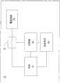
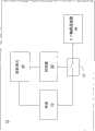
请参照图1,图1为本发明的计算机周边的非接触式感应装置的方块示意图。Please refer to FIG. 1 . FIG. 1 is a schematic block diagram of a non-contact sensing device around a computer according to the present invention.
非接触式感应装置10包括电源12、发射单元20、控制器30及感应单元40。非接触式感应装置10可为一数字板。非接触式感应装置10对应数字指向装置50,并且数字指向装置50可设置于非接触式感应装置10的工作区域内。使用者操控指向装置50,即可运用此非接触式感应装置10来对于计算机进行操作。The
电源12用以产生一电源信号。电源12可接受由通用序列总线(UniversalSerial Bus,USB)或是可由电池供电,亦可由交流电经变压器转换成直流电后所产生的电源12。The
电源12电性连接至发射单元20、控制器30及感应单元40。The
当发射单元20接收到电源信号后,会将电源信号转换成一震荡信号,并且传送给数字指向装置50。当数字指向装置50中的第一线圈52接收到震荡信号后,会将震荡信号转换成能量储存,并由第二线圈54传送震荡信号到感应组件40。When the transmitting
感应单元40接收到数字指向装置50传送回来的震荡信号后,会将其转换成一感应信号。After receiving the oscillating signal sent back from the digital pointing device 50 , the
控制器30根据感应信号,输出不同时间长度比例的启动信号及停止信号给发射单元20及感应单元40,以进行动态式切换。The
该控制器30具有第一状态与第二状态。在第一状态下,启动信号与停止信号之间的时间长度比为第一比例。在第二状态下,启动信号与停止信号之间的时间长度比为第二比例。当控制器30检测到感应单元40产生感应信号时,代表数字指向装置50置于感应组件40的工作区域中,控制器30可将其状态设定为为第二状态。当控制器30未检测到感应单元40时,控制器30可将其状态设定为为第一状态。其中,第一状态中停止信号所占的比例大于第二状态中停止信号所占的比例。The
当数字指向装置50置于感应单元40的工作区域内时,感应单元40根据数字指向装置50传送回来的震荡信号的振幅大小来产生感应信号。感应信号代表数字指向装置50的位置。When the digital pointing device 50 is placed in the working area of the
在本发明的一实施例中,当发射单元20接收到启动信号时,发射单元20会产生出震荡信号;反之,当发射单元20接收到停止信号时,发射单元20会终止产生出震荡信号。也就是说,发射单元20可间断地产生震荡信号。此外,发射单元20可根据不同比例(第一比例或是第二比例)而产生不同长度的震荡信号。In an embodiment of the present invention, when the transmitting
另外,当感应单元40接收到启动信号时,感应单元40产生感应信号;反之,当感应单元40接收到停止信号时,感应组件40终止产生感应信号。因此,感应组件40所需要的电能也可以被节省。In addition, when the
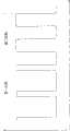
请参照图2,图2为本发明的计算机周边的非接触式感应装置的第一实施例的信号时序示意图。Please refer to FIG. 2 . FIG. 2 is a signal timing diagram of the first embodiment of the non-contact sensing device around the computer according to the present invention.
在此图中,启动信号为一高准位信号(逻辑1),且停止信号为低准位信号(逻辑0)。在第一状态下,启动信号与停止信号的第一比例为20%比80%。在第二状态下,启动信号与停止信号的第二比例为50%比50%。In this figure, the start signal is a high level signal (logic 1), and the stop signal is a low level signal (logic 0). In the first state, the first ratio of the start signal to the stop signal is 20% to 80%. In the second state, the second ratio of the start signal to the stop signal is 50% to 50%.
也就是说,在第一状态下,发射单元20只有20%的时间会产生第一震荡信号。因此,在第一状态下,非接触式感应装置10可以节省下许多的电力消耗。That is to say, in the first state, the transmitting
虽上述实施例公开了特定的比例,然本发明并不以此为限。Although the above embodiments disclose specific proportions, the present invention is not limited thereto.
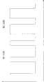
请参照图3,图3为本发明的计算机周边的非接触式感应装置的第二实施例的信号时序示意图。Please refer to FIG. 3 . FIG. 3 is a signal timing diagram of a second embodiment of a non-contact sensing device around a computer according to the present invention.
在第一状态下,启动信号与停止信号的第一比例为10%比90%。在第二状态下,启动信号与停止信号的第二比例为40%比60%。In the first state, the first ratio of the start signal to the stop signal is 10% to 90%. In the second state, the second ratio of the start signal to the stop signal is 40% to 60%.
在第一状态下,发射单元40只有10%的时间会产生第一震荡信号。也就是说,此非接触式感应装置10可以达到较佳的省电效果。In the first state, the transmitting
请参照图4,图4为本发明的计算机周边的非接触式感应装置的第三实施例的信号时序示意图。Please refer to FIG. 4 . FIG. 4 is a signal timing diagram of a third embodiment of a non-contact sensing device around a computer according to the present invention.
在第一状态下,启动信号与停止信号的第一比例为30%比70%。在第二状态下,启动信号与停止信号的第二比例为60%比40%。In the first state, the first ratio of the start signal to the stop signal is 30% to 70%. In the second state, the second ratio of the start signal to the stop signal is 60% to 40%.
在第二状态下,发射单元20会有60%的时间会产生第一震荡信号。也就是说,当数字指向装置50置于非接触式感应装置10上时,数字指向装置50可获得较佳的充电效果。In the second state, the transmitting
请参照图5A与图5B,图5A与图5B为本发明的发射单元示意图。发射单元20包括一开关22及一震荡电路24,该震荡电路24与电源12之间以开关22电性连接,该开关22也电性连接至控制器30。在图5A中,当控制器30输出启动信号,开关22导通电源12与震荡电路24。在图5B中,当控制器30输出停止信号,开关22截断电源12与震荡电路24。Please refer to FIG. 5A and FIG. 5B . FIG. 5A and FIG. 5B are schematic diagrams of the transmitting unit of the present invention. The transmitting
请参照图6A与图6B,图6A与图6B为本发明的感应单元示意图。感应单元40包括一开关42与一双轴感应线圈44。双轴感应线圈44与电源12之间以开关42电性连接,该开关42也电性连接至控制器30。在图6A中,当控制器30输出启动信号,开关42导通电源12与双轴感应线圈44。在图6B中,当控制器30输出停止信号,开关42截断电源12与双轴感应线圈44。Please refer to FIG. 6A and FIG. 6B . FIG. 6A and FIG. 6B are schematic diagrams of the sensing unit of the present invention. The
当数字指向装置50未置于感应组件40的工作区域内时,可以藉由动态地调整启动信号与停止信号之间的时间长度比例,让非接触式感应装置10仅消耗非常少量的电能。当数字指向装置50置于感应组件40的工作区域内时,也藉由动态地调整启动信号与停止信号之间的时间长度比例,让非接触式感应装置10以适当强度的电能提供给数字指向装置50。因此,非接触式感应装置10可以大幅节省的电能消耗。When the digital pointing device 50 is not placed in the working area of the
请参照图7为本发明所提出的非接触式感应方法的流程图。一种计算机周边的非接触式感应方法,与一数字指向装置相互搭配使用,该非接触式感应方法,其步骤包括:Please refer to FIG. 7 , which is a flow chart of the non-contact sensing method proposed by the present invention. A non-contact sensing method around a computer is used in conjunction with a digital pointing device. The non-contact sensing method comprises:
在步骤S101中,提供一电源信号。In step S101, a power signal is provided.
在步骤S103中,将电源信号转换成一震荡信号,并传送给数字指向装置。In step S103, the power signal is converted into an oscillating signal and sent to the digital pointing device.
在步骤S105中,接收数字指向装置传送回来的震荡信号并转换成感应信号。In step S105, the oscillating signal sent back by the digital pointing device is received and converted into an induction signal.
在步骤S107中,根据感应信号,输出不同时间长度比例的启动信号及停止信号,以进行动态式切换。In step S107, according to the sensing signal, a start signal and a stop signal with different time length ratios are outputted to perform dynamic switching.
其中该动态式切换为利用启动信号及停止信号来控制震荡信号及感应信号是在不同时间相互产生。Wherein the dynamic switching is to use the start signal and the stop signal to control the oscillation signal and the induction signal to be mutually generated at different times.
在此流程中,具有第一状态及第二状态。该第一状态的停止信号时间的长度比例会大于第二状态的停止信号时间的长度比例。In this flow, there is a first state and a second state. The length ratio of the stop signal time in the first state is greater than the length ratio of the stop signal time in the second state.
Claims (9)
Priority Applications (1)
| Application Number | Priority Date | Filing Date | Title |
|---|---|---|---|
| CN2011101119442ACN102760022A (en) | 2011-04-27 | 2011-04-27 | Non-contact sensing device and method around computer |
Applications Claiming Priority (1)
| Application Number | Priority Date | Filing Date | Title |
|---|---|---|---|
| CN2011101119442ACN102760022A (en) | 2011-04-27 | 2011-04-27 | Non-contact sensing device and method around computer |
Publications (1)
| Publication Number | Publication Date |
|---|---|
| CN102760022Atrue CN102760022A (en) | 2012-10-31 |
Family
ID=47054492
Family Applications (1)
| Application Number | Title | Priority Date | Filing Date |
|---|---|---|---|
| CN2011101119442APendingCN102760022A (en) | 2011-04-27 | 2011-04-27 | Non-contact sensing device and method around computer |
Country Status (1)
| Country | Link |
|---|---|
| CN (1) | CN102760022A (en) |
Citations (6)
| Publication number | Priority date | Publication date | Assignee | Title |
|---|---|---|---|---|
| JPH02272617A (en)* | 1989-04-14 | 1990-11-07 | Wacom Co Ltd | Position detector |
| CN201435623Y (en)* | 2009-05-06 | 2010-03-31 | 昆盈企业股份有限公司 | Digital board of battery-free wireless pointer element |
| US20100170726A1 (en)* | 2009-01-06 | 2010-07-08 | Elan Microelectronics Corporation | Electronic stylus, capacitive touchpad module, and apparatus for touch input |
| CN201654756U (en)* | 2009-10-09 | 2010-11-24 | 昆盈企业股份有限公司 | Digital board of battery-free wireless pointer assembly |
| CN201673459U (en)* | 2010-01-27 | 2010-12-15 | 昆盈企业股份有限公司 | radio frequency mouse |
| CN102023698A (en)* | 2009-09-11 | 2011-04-20 | 昆盈企业股份有限公司 | Power-saving management method and system for computer peripheral device |
- 2011
- 2011-04-27CNCN2011101119442Apatent/CN102760022A/enactivePending
Patent Citations (6)
| Publication number | Priority date | Publication date | Assignee | Title |
|---|---|---|---|---|
| JPH02272617A (en)* | 1989-04-14 | 1990-11-07 | Wacom Co Ltd | Position detector |
| US20100170726A1 (en)* | 2009-01-06 | 2010-07-08 | Elan Microelectronics Corporation | Electronic stylus, capacitive touchpad module, and apparatus for touch input |
| CN201435623Y (en)* | 2009-05-06 | 2010-03-31 | 昆盈企业股份有限公司 | Digital board of battery-free wireless pointer element |
| CN102023698A (en)* | 2009-09-11 | 2011-04-20 | 昆盈企业股份有限公司 | Power-saving management method and system for computer peripheral device |
| CN201654756U (en)* | 2009-10-09 | 2010-11-24 | 昆盈企业股份有限公司 | Digital board of battery-free wireless pointer assembly |
| CN201673459U (en)* | 2010-01-27 | 2010-12-15 | 昆盈企业股份有限公司 | radio frequency mouse |
Similar Documents
| Publication | Publication Date | Title |
|---|---|---|
| TWI403066B (en) | Battery plate for battery-free indicator element and power supply method of digital plate using battery-free wireless indicator element | |
| CN103248130B (en) | Method for low-loss data transmission in high-power inductive power supply | |
| CN201699462U (en) | Wireless charging device | |
| CN103279233B (en) | Wireless mouse power supply system | |
| KR101006187B1 (en) | Wireless Resonance Power Charging System | |
| TWI510977B (en) | Input system and electromagnetic charging method | |
| CN203643943U (en) | Multifunctional starting circuit and Bluetooth product | |
| TWI453629B (en) | Free battery wireless indicator components of the tablet | |
| CN202422005U (en) | Wireless charging type pointer input device | |
| CN206211626U (en) | Coupled resonance wireless charging portable power source based on frequency-tracking | |
| CN102760022A (en) | Non-contact sensing device and method around computer | |
| CN204044764U (en) | A kind of charge wireless mouse | |
| CN208092680U (en) | A kind of wireless charging mouse | |
| CN103997077A (en) | Wifi (Wireless Fidelity), controllable, intelligent and wireless charging conference table | |
| CN202602976U (en) | A remote control with USB and sleep wake-up device | |
| CN201654756U (en) | Digital board of battery-free wireless pointer assembly | |
| US20120271971A1 (en) | Non-contact sensing device and its method for computer peripherals | |
| CN202957642U (en) | A non-contact power supply device | |
| CN104331304A (en) | Standby waking-up method of external notebook computer of audio equipment | |
| CN104102364A (en) | Wirelessly power-taking wireless mouse with USB (Universal Serial Bus) interface | |
| CN202939572U (en) | Wireless charging mouse | |
| TW201133323A (en) | Electromagnetic touch displayer | |
| TWM564196U (en) | Intelligent wireless power-supplying mouse pad | |
| CN202854742U (en) | Wireless power transmission mouse | |
| CN203102199U (en) | Touch panel and touch device |
Legal Events
| Date | Code | Title | Description |
|---|---|---|---|
| C06 | Publication | ||
| PB01 | Publication | ||
| C10 | Entry into substantive examination | ||
| SE01 | Entry into force of request for substantive examination | ||
| C02 | Deemed withdrawal of patent application after publication (patent law 2001) | ||
| WD01 | Invention patent application deemed withdrawn after publication | Application publication date:20121031 |