CN102756752A - Haptic steering wheel switch apparatus - Google Patents
Haptic steering wheel switch apparatusDownload PDFInfo
- Publication number
- CN102756752A CN102756752ACN2012101254167ACN201210125416ACN102756752ACN 102756752 ACN102756752 ACN 102756752ACN 2012101254167 ACN2012101254167 ACN 2012101254167ACN 201210125416 ACN201210125416 ACN 201210125416ACN 102756752 ACN102756752 ACN 102756752A
- Authority
- CN
- China
- Prior art keywords
- button
- unit
- tactile
- sense
- touch
- Prior art date
- Legal status (The legal status is an assumption and is not a legal conclusion. Google has not performed a legal analysis and makes no representation as to the accuracy of the status listed.)
- Granted
Links
Images


Classifications
- G—PHYSICS
- G06—COMPUTING OR CALCULATING; COUNTING
- G06F—ELECTRIC DIGITAL DATA PROCESSING
- G06F3/00—Input arrangements for transferring data to be processed into a form capable of being handled by the computer; Output arrangements for transferring data from processing unit to output unit, e.g. interface arrangements
- G06F3/01—Input arrangements or combined input and output arrangements for interaction between user and computer
- G06F3/016—Input arrangements with force or tactile feedback as computer generated output to the user
- G—PHYSICS
- G06—COMPUTING OR CALCULATING; COUNTING
- G06F—ELECTRIC DIGITAL DATA PROCESSING
- G06F3/00—Input arrangements for transferring data to be processed into a form capable of being handled by the computer; Output arrangements for transferring data from processing unit to output unit, e.g. interface arrangements
- G06F3/01—Input arrangements or combined input and output arrangements for interaction between user and computer
- G06F3/03—Arrangements for converting the position or the displacement of a member into a coded form
- G06F3/033—Pointing devices displaced or positioned by the user, e.g. mice, trackballs, pens or joysticks; Accessories therefor
- G06F3/0338—Pointing devices displaced or positioned by the user, e.g. mice, trackballs, pens or joysticks; Accessories therefor with detection of limited linear or angular displacement of an operating part of the device from a neutral position, e.g. isotonic or isometric joysticks
- G—PHYSICS
- G06—COMPUTING OR CALCULATING; COUNTING
- G06F—ELECTRIC DIGITAL DATA PROCESSING
- G06F3/00—Input arrangements for transferring data to be processed into a form capable of being handled by the computer; Output arrangements for transferring data from processing unit to output unit, e.g. interface arrangements
- G06F3/01—Input arrangements or combined input and output arrangements for interaction between user and computer
- G06F3/03—Arrangements for converting the position or the displacement of a member into a coded form
- G06F3/033—Pointing devices displaced or positioned by the user, e.g. mice, trackballs, pens or joysticks; Accessories therefor
- G06F3/0362—Pointing devices displaced or positioned by the user, e.g. mice, trackballs, pens or joysticks; Accessories therefor with detection of 1D translations or rotations of an operating part of the device, e.g. scroll wheels, sliders, knobs, rollers or belts
Landscapes
- Engineering & Computer Science (AREA)
- General Engineering & Computer Science (AREA)
- Theoretical Computer Science (AREA)
- Human Computer Interaction (AREA)
- Physics & Mathematics (AREA)
- General Physics & Mathematics (AREA)
- Steering Controls (AREA)
- Switches With Compound Operations (AREA)
- Mechanical Control Devices (AREA)
Abstract
Description
Translated fromChinese技术领域technical field
本发明涉及一种开关装置,更具体地说,涉及这样一种具有简单结构的开关装置,该开关装置实现了驾驶员在操纵方向盘上的平稳操作,允许驾驶员进行快速感知,并且允许进行多方位的操纵和按压操作,以便可以为装置选择各种操作模式。The present invention relates to a switchgear, and more particularly, to a switchgear with a simple structure that realizes a driver's smooth operation on the steering wheel, allows the driver to perform quick perception, and allows multiple Orientation and push operation so that various operating modes can be selected for the device.
背景技术Background technique
开关装置被用作用于对诸如车辆、机床、终端、多媒体装置、游戏机等设备进行选择和操纵的装置。然而,也在进行关于用于所述设备的不同功能选择的开关装置的各种研究和开发。除了简单的按压开关类型的按钮开关之外,这样的开关装置的示例包括能够轴向旋转的旋转开关。此外,对于具有不同修改结构的旋转开关进行了各种研究和制造。Switch devices are used as devices for selecting and manipulating equipment such as vehicles, machine tools, terminals, multimedia devices, game machines, and the like. However, various researches and developments are also being carried out regarding switching means for different function selections of the device. Examples of such switch devices include rotary switches capable of axial rotation, in addition to simple push switch type push button switches. In addition, various studies and manufactures have been conducted on rotary switches with different modified structures.
同时,由于开关装置所操纵的对象具有复杂而多样的功能,因此开关装置需要用于选择组合的层次操作的功能并能够通过逐步操作而能够具有层次操作功能。然而,这样的常规开关装置带来这样的缺点,即,该装置仅仅具有其中用于发出照明光的光源设置在布置于开关装置的开关旋钮上的图标处的构造,并且由于其不执行与各种操作模式相对应的主动显示功能因此使用者遭受必须注意分离的显示屏带来的不便性。也就是说,常规的开关装置涉及这样的问题,即,由于使用者必须同时注意开关装置的开关旋钮和显示屏以操纵开关装置,所以开关装置的操纵是不方便的,或者在开关装置安装在车辆上的情况下驾驶员的驾驶注意力被分散,从而降低了车辆的驾驶安全性。此外,另一种常规的开关装置具有其中显示装置和开关装置彼此一体化的静电电容型开关结构。然而,常规的触摸开关具有对其操纵的弱响应性,从而使用者不会感到直接操纵的感觉。Meanwhile, since the objects manipulated by the switch device have complex and various functions, the switch device needs a function for selecting a combined hierarchical operation and can have a hierarchical operation function through step-by-step operations. However, such a conventional switch device has the disadvantage that the device only has a configuration in which a light source for emitting illuminating light is provided at an icon arranged on a switch knob of the switch device, and since it does not perform a function related to each The active display function corresponding to the two operating modes thus the user suffers from the inconvenience of having to pay attention to a separate display screen. That is, the conventional switch device involves such a problem that since the user must pay attention to the switch knob and the display screen of the switch device at the same time to operate the switch device, the manipulation of the switch device is inconvenient, or the switch device is mounted on a The driver's driving attention is distracted under the situation on the vehicle, thereby reducing the driving safety of the vehicle. Furthermore, another conventional switch device has an electrostatic capacitance type switch structure in which a display device and a switch device are integrated with each other. However, conventional touch switches have weak responsiveness to manipulation thereof, so that the user does not feel a sense of direct manipulation.
发明内容Contents of the invention
因此,本发明的目的是提供一种具有简单结构的触觉式方向盘开关设备,所述触觉式方向盘开关设备安装在车辆的方向盘上,具有紧凑尺寸,可以显著降低制造成本,并且改善了其操纵性。Therefore, an object of the present invention is to provide a tactile steering wheel switch device having a simple structure, which is mounted on a steering wheel of a vehicle, has a compact size, can significantly reduce manufacturing costs, and has improved manipulability thereof .
为了实现上述目的,在一个方面,本发明提供了一种触觉式方向盘开关设备,其包括:触觉轮外壳单元,该触觉轮外壳单元被构造成设置在车辆方向盘上;电路板单元,该电路板单元被构造成设置在触觉轮外壳单元内部;和触觉轮装置,该触觉轮装置包括触觉轮装置致动器、触觉旋钮和触觉轮装置感测单元,所述触觉轮装置致动器被构造成与所述电路板单元建立电连接并包括触觉轴,所述触觉旋钮与所述触觉轴相连并暴露地设置在触觉轮外壳单元中,所述触觉轮装置感测单元被构造成检测所述触觉轴的旋转状态,所述触觉旋钮在供布置所述车辆方向盘的布置平面上可实现旋转操作,并且所述触觉轮装置致动器沿所述触觉轴的纵向竖直地移动。In order to achieve the above object, in one aspect, the present invention provides a tactile steering wheel switch device, which includes: a tactile wheel housing unit configured to be arranged on a vehicle steering wheel; a circuit board unit, the circuit board a unit configured to be disposed inside the tactile wheel housing unit; and a tactile wheel device comprising a tactile wheel device actuator, a tactile knob, and a tactile wheel device sensing unit, the tactile wheel device actuator being configured to Establishing electrical connection with the circuit board unit and including a tactile shaft, the tactile knob is connected with the tactile shaft and exposed in the tactile wheel housing unit, the tactile wheel device sensing unit is configured to detect the tactile According to the rotation state of the shaft, the tactile knob can realize the rotation operation on the layout plane where the vehicle steering wheel is arranged, and the actuator of the tactile wheel device moves vertically along the longitudinal direction of the tactile shaft.
在该触觉式方向盘开关设备中,所述触觉轮装置致动器的所述触觉轴可包括分别形成在该触觉轴的两端的第一末端和第二末端。In the tactile steering wheel switch apparatus, the tactile shaft of the tactile wheel device actuator may include first and second ends respectively formed at both ends of the tactile shaft.
在该触觉式方向盘开关设备中,所述触觉旋钮可与所述触觉轴的所述第一末端相连,并且所述触觉轮装置感测单元与所述触觉轴的所述第二末端相连。In the tactile steering wheel switch device, the tactile knob may be connected to the first end of the tactile shaft, and the tactile wheel device sensing unit may be connected to the second end of the tactile shaft.
在该触觉式方向盘开关设备中,在所述触觉旋钮和所述触觉轴的所述第一末端之间可设置轴旋钮保持器,以防止所述触觉旋钮和所述第一末端之间的相对旋转。In the tactile steering wheel switch device, a shaft knob holder may be provided between the tactile knob and the first end of the tactile shaft to prevent relative contact between the tactile knob and the first end. rotate.
在该触觉式方向盘开关设备中,在所述触觉轮装置感测单元和所述触觉轴的所述第二末端之间可设置轴感测保持器,以防止所述触觉轮装置感测单元和所述第二末端之间的相对旋转。In this tactile steering wheel switch device, a shaft sensing holder may be provided between the tactile wheel device sensing unit and the second end of the tactile shaft to prevent the tactile wheel device sensing unit and relative rotation between the second ends.
在该触觉式方向盘开关设备中,所述触觉轮装置感测单元可包括:与所述触觉轮装置致动器相连的装置感测主体部;和装置检测传感器部,该装置检测传感器部被构造成检测所述装置感测主体部的旋转状态,其中所述装置感测主体部包括:装置感测主带轮,该装置感测主带轮以使得所述装置感测主带轮和所述轴感测保持器之间的相对旋转被限制的方式与所述轴感测保持器相连;装置感测副带轮,该装置感测副带轮以与所述装置感测主带轮间隔开的方式与所述装置感测主带轮相连;装置感测带,该装置感测带被构造成将所述装置感测主带轮与所述装置感测副带轮互连;和装置狭槽,该装置狭槽连接到所述装置感测副带轮并被构造成当所述装置感测副带轮旋转时与所述装置感测副带轮一起旋转,所述装置狭槽以可旋转的方式设置在与所述装置检测传感器部相对应的位置处。In the tactile steering wheel switch apparatus, the tactile wheel device sensing unit may include: a device sensing body part connected to the tactile wheel device actuator; and a device detection sensor part configured to detect the rotational state of the device-sensing main body portion, wherein the device-sensing main body portion includes: a device-sensing primary pulley, the device-sensing primary pulley such that the device-sensing primary pulley and the device-sensing primary pulley connected to said shaft sensing holder in such a way that relative rotation between said shaft sensing holders is limited; a device sensing secondary pulley spaced apart from said device sensing primary pulley connected to said device-sensing primary pulley in a manner; a device-sensing belt configured to interconnect said device-sensing primary pulley with said device-sensing secondary pulley; and a device-sensing belt a slot connected to the device sensing secondary pulley and configured to rotate together with the device sensing secondary pulley when the device sensing secondary pulley rotates, the device slot being configured to The means of rotation is provided at a position corresponding to the device detection sensor part.
在该触觉式方向盘开关设备中,装置感测主带轮与装置感测副带轮的旋转比可大于1。In the tactile steering wheel switch apparatus, a rotation ratio of the device sensing primary pulley to the device sensing secondary pulley may be greater than 1.
该触觉式方向盘开关设备还可包括按压开关单元,该按压开关单元被构造成当所述触觉旋钮沿所述触觉轴的纵向竖直移动时产生切换信号。The tactile steering wheel switch device may further include a push switch unit configured to generate a switching signal when the tactile knob is vertically moved along the longitudinal direction of the tactile shaft.
在该触觉式方向盘开关设备中,所述按压开关单元可包括:按压开关,该按压开关设置在所述电路板单元上;和按压开关操作部,该按压开关操作部被构造成与所述触觉轮装置致动器一起竖直地移动。In the tactile steering wheel switch device, the push switch unit may include: a push switch provided on the circuit board unit; The wheel arrangement actuators move vertically together.
在该触觉式方向盘开关设备中,所述按压开关可以多个数量提供。In the tactile steering wheel switch device, the push switches may be provided in plural numbers.
在该触觉式方向盘开关设备中,所述触觉轮装置感测单元可与触觉轮装置致动器一起竖直地移动。In the tactile steering wheel switch apparatus, the tactile wheel device sensing unit is vertically movable together with the tactile wheel device actuator.
在该触觉式方向盘开关设备中,所述触觉旋钮可由透光材料形成,所述电路板单元包括旋钮板,该旋钮板被构造成允许所述触觉轴的所述第一末端从该旋钮板穿过并充当所述触觉轮装置致动器的末端,并且在所述旋钮板上安装触觉旋钮光源单元以输出光。In the tactile steering wheel switch device, the tactile knob may be formed of a light-transmitting material, and the circuit board unit includes a knob board configured to allow the first end of the tactile shaft to pass through the knob board. and serve as the end of the actuator of the tactile wheel device, and a tactile knob light source unit is installed on the knob plate to output light.
在该触觉式方向盘开关设备中,在所述触觉旋钮的外部可设置按钮开关单元,使得该按钮开关单元独立于所述触觉旋钮竖直地操作。In the tactile steering wheel switch device, a push button switch unit may be provided outside the tactile knob such that the push button switch unit is vertically operated independently of the tactile knob.
在该触觉式方向盘开关设备中,按钮开关单元可包括:按钮,所述按钮设置在所述触觉旋钮的外部,所述触觉旋钮设置成使得该其一个表面暴露于所述触觉轮外壳单元的外部;按钮引导部,该按钮引导部被构造成在其一端设置在按钮内部,并且在其另一端朝向所述电路板单元设置在所述触觉轮外壳单元内部;按钮引导部保持器,该按钮引导部保持器被构造成附接到所述按钮引导部并以能与所述按钮引导部一起可竖直地稳定运动的方式设置在所述触觉轮外壳单元内;和按钮开关,该按钮开关被构造成以使得与所述按钮引导部保持器紧密接触的方式设置在所述电路板单元的一个表面上。In the tactile steering wheel switch device, the button switch unit may include: a button provided outside the tactile knob, the tactile knob provided such that one surface thereof is exposed to the outside of the tactile wheel housing unit. a button guide, which is configured to be disposed inside the button at one end thereof, and disposed inside the tactile wheel housing unit at its other end toward the circuit board unit; a button guide holder, which guides the button a part holder configured to be attached to the button guide and provided within the tactile wheel housing unit in a manner capable of vertically and stably moving together with the button guide; and a button switch, which is held It is configured to be provided on one surface of the circuit board unit so as to be in close contact with the button guide holder.
在该触觉式方向盘开关设备中,所述按钮引导部保持器可包括形成在该按钮引导部保持器的一侧的按钮引导部保持器止挡件,并且所述触觉轮外壳单元包括轮外壳主体止挡件,该轮外壳主体止挡件在所述触觉轮外壳单元上形成为使得与所述按钮引导部保持器止挡件紧密接触以与所述按钮引导部保持器止挡件对应,从而防止所述按钮引导部保持器与所述触觉轮外壳单元的所述轮外壳主体分离而脱离所述轮外壳主体。In the tactile steering wheel switch apparatus, the button guide holder may include a button guide holder stopper formed on one side of the button guide holder, and the tactile wheel housing unit includes a wheel housing main body. a stopper, the wheel housing body stopper is formed on the tactile wheel housing unit so as to be in close contact with the button guide retainer stopper to correspond to the button guide retainer stopper, thereby The button guide retainer is prevented from being separated from the wheel housing body of the tactile wheel housing unit from the wheel housing body.
在该触觉式方向盘开关设备中,所述按钮引导部保持器可包括被构造成操作所述按钮开关的按钮引导部保持器操作部。In the tactile steering wheel switch device, the button guide holder may include a button guide holder operating portion configured to operate the push button switch.
在该触觉式方向盘开关设备中,所述按钮开关单元还可包括按钮光源单元,并且所述按钮引导部由导光材料形成。In the tactile steering wheel switch device, the button switch unit may further include a button light source unit, and the button guide is formed of a light guide material.
在该触觉式方向盘开关设备中,所述按钮引导部保持器操作部可包括按钮引导部保持器操作部安放面,该按钮引导部保持器操作部安放面形成在所述按钮引导部保持器操作部的一个表面上,从而与所术按钮引导部紧密接触以支撑所述按钮引导部。In the tactile steering wheel switch device, the button guide holder operation part may include a button guide holder operation part seating surface formed on the button guide holder operation part. On one surface of the part, so as to be in close contact with the button guide part to support the button guide part.
在该触觉式方向盘开关设备中,在按钮引导部和按钮之间可设置按钮滤色器,以仅透射具有预定频带的光。In the tactile steering wheel switch device, a button color filter may be provided between the button guide and the button to transmit only light having a predetermined frequency band.
在该触觉式方向盘开关设备中,所述触觉旋钮可包括在其一个表面上形成的凹入形状的触觉旋钮凹陷,所述触觉旋钮凹陷具有这样的结构,即:沿垂直于所述触觉旋钮的旋转中心的方向形成在的凹陷深度,从所述触觉旋钮的中心沿径向方向逐渐减小。In the tactile steering wheel switch device, the tactile knob may include a concave-shaped tactile knob depression formed on one surface thereof, the tactile knob depression having a structure such that a direction perpendicular to the tactile knob The direction of the center of rotation is formed at a depth of the recess that gradually decreases from the center of the tactile knob in a radial direction.
在该触觉式方向盘开关设备中,所述触觉旋钮可包括触觉旋钮抓握部,该触觉旋钮抓握部突出地形成在所述触觉旋钮的一个表面上。In the tactile steering wheel switch apparatus, the tactile knob may include a tactile knob grip protrudingly formed on one surface of the tactile knob.
在该触觉式方向盘开关设备中,所述触觉旋钮可包括触觉旋钮接触表面,该触觉旋钮接触表面以双料注射(dual injection)方式形成在所述触觉旋钮的顶部上,以增加驾驶员的手指和所述触觉旋钮之间的接触摩擦力。In the tactile steering wheel switch device, the tactile knob may include a tactile knob contact surface formed on the top of the tactile knob in a dual injection manner to increase the driver's finger and contact surface. Contact friction between the tactile knobs.
该触觉式方向盘开关设备还可以包括:控制单元,所述控制单元被构造成与所述触觉方向盘开关设备建立电连接;和存储单元,所述存储单元被构造成与所述控制单元建立电连接并且存储用于预定操作模式的预定数据。The tactile steering wheel switch device may further include: a control unit configured to establish electrical connection with the tactile steering wheel switch device; and a storage unit configured to establish electrical connection with the control unit And storing predetermined data for a predetermined mode of operation.
为了实现以上目的,在其它方面,本发明提供了一种触觉式方向盘开关设备,该触觉式方向盘开关设备包括:触觉轮外壳单元,所述触觉轮外壳单元设置在车辆方向盘上;电路板单元,所述电路板单元设置在所述触觉轮外壳单元中;和触觉轮装置单元,所述触觉轮装置单元包括触觉轮装置致动器触觉旋钮和触觉轮装置感测单元,所述触觉轮装置致动器与所述电路板单元建立电连接并包括触觉轴,所述触觉旋钮与所述触觉轴相连并暴露地设置在所述触觉轮外壳单元的一个表面上,所述触觉轮装置感测单元用于检测所述触觉轴的旋转状态,其中,所述触觉旋钮在由所述车辆方向盘形成的平面上实现旋转操作,所述触觉轮装置致动器沿着所述触觉轴的纵向移动,并且独立于所述触觉旋钮竖直地操作的按钮开关单元设置在所述触觉旋钮的外部。In order to achieve the above object, in other respects, the present invention provides a tactile steering wheel switch device, the tactile steering wheel switch device includes: a tactile wheel housing unit, the tactile wheel housing unit is arranged on the vehicle steering wheel; a circuit board unit, The circuit board unit is disposed in the tactile wheel housing unit; and a tactile wheel device unit, the tactile wheel device unit includes a tactile wheel device actuator tactile knob and a tactile wheel device sensing unit, the tactile wheel device causes The actuator establishes an electrical connection with the circuit board unit and includes a tactile shaft, the tactile knob is connected to the tactile shaft and is exposed on one surface of the tactile wheel housing unit, and the tactile wheel device sensing unit for detecting the rotational state of the tactile shaft, wherein the tactile knob is rotated on a plane formed by the vehicle steering wheel, the tactile wheel device actuator is moved longitudinally along the tactile shaft, and A button switch unit vertically operating independently of the tactile knob is provided outside the tactile knob.
在该触觉式方向盘开关设备中,所述按钮开关单元包括:按钮,所述按钮设置在所述触觉旋钮的外部,该按钮设置成使得其一个表面暴露于所述触觉轮外壳单元的外部;按钮引导部,所述按钮引导部的一端设置在所述按钮旋钮内,并且该按钮引导部的另一端朝向所述电路板单元设置在所述触觉轮外壳单元内,朝向所述电路板单元;按钮引导部保持器,所述按钮引导部保持器附接到所述按钮引导部并以能与所述按钮引导部一起竖直地移动的方式设置在所述触觉轮外壳单元中;和按钮开关,所述按钮开关包括按钮开关磁体、按钮开关磁性传感器和按钮开关弹性单元,所述按钮开关磁体设置在所述按钮引导部保持器中,所述按钮开关磁性传感器设置在所述电路板单元的一个表面上以与所述按钮开关磁体分隔开,所述按钮开关弹性单元用于弹性地支撑所述按钮引导部。In the tactile steering wheel switch device, the push button switch unit includes: a button disposed outside the tactile knob, the button disposed such that one surface thereof is exposed to the outside of the tactile wheel housing unit; a guide part, one end of the button guide part is arranged in the button knob, and the other end of the button guide part is arranged in the tactile wheel housing unit toward the circuit board unit, facing the circuit board unit; a guide holder attached to the button guide and provided in the tactile wheel housing unit in a manner to be vertically movable together with the button guide; and a push button switch, The button switch includes a button switch magnet, a button switch magnetic sensor and a button switch elastic unit, the button switch magnet is arranged in the button guide holder, the button switch magnetic sensor is arranged in one of the circuit board units The push-button switch magnet is separated from the push-button switch on the surface, and the push-button switch elastic unit elastically supports the push-button guide.
在该触觉式方向盘开关设备中,所述按钮开关单元还包括设置在所述电路板单元上的按钮光源单元,并且所述按钮引导部由导光材料形成。In the tactile steering wheel switch device, the button switch unit further includes a button light source unit provided on the circuit board unit, and the button guide is formed of a light guide material.
在该触觉式方向盘开关设备中,所述按钮光源单元包括用于输出第一波长光的第一波长光源和用于输出第二波长光的第二波长光源,所述第二波长光的波长带不同于所述第一波长光的波长带,并且所述按钮开关单元还包括按钮滤光器单元,所述按钮滤光器单元用于选择性使所述第一波长光或所述第二波长光从其穿过并且通过根据所述按钮光源单元的操作改变光的输出区域来指示可变符号。In this tactile steering wheel switch device, the button light source unit includes a first wavelength light source for outputting first wavelength light and a second wavelength light source for outputting second wavelength light, the wavelength band of the second wavelength light a wavelength band different from the first wavelength light, and the button switch unit further includes a button filter unit for selectively enabling the first wavelength light or the second wavelength Light passes therethrough and indicates a variable symbol by changing an output area of light according to the operation of the button light source unit.
在该触觉式方向盘开关设备中,所述按钮滤光器单元包括:按钮筛选过滤器单元,所述按钮筛选过滤器单元设置成面对所述按钮光源单元并且选择性允许所述第一波长光或所述第二波长光从其穿过;和按钮半透明过滤器单元,所述按钮半透明过滤器单元定位成将所述按钮筛选过滤器单元设置在所述按钮半透明过滤器单元和所述按钮光源单元之间,并且根据穿过所述按钮筛选过滤器单元的所述第一波长光或所述第二波长光来改变光的输出区域。In the tactile steering wheel switch device, the button filter unit includes: a button screening filter unit disposed to face the button light source unit and selectively allowing light of the first wavelength or said second wavelength light passing therethrough; and a button translucent filter unit positioned to place said button screening filter unit between said button translucent filter unit and said button translucent filter unit between the button light source units, and change the output area of light according to the first wavelength light or the second wavelength light passing through the button filtering filter unit.
在该触觉式方向盘开关设备中,所述按钮筛选过滤器单元包括:按钮光全透单元,所述按钮光全透单元用于使所述第一波长光和所述第二波长光都从其穿过;按钮选择性透光单元,所述按钮选择性透光单元用于使所述第一波长光和所述第二波长光中的任一者从其穿过;和按钮光全阻单元,所述按钮光全阻单元用于阻挡所述第一波长光和所述第二波长光二者。In the tactile steering wheel switch device, the button screening filter unit includes: a button light fully transparent unit, and the button light fully transparent unit is used to make both the first wavelength light and the second wavelength light pass through passing through; a button selective light-transmitting unit for allowing any one of the first wavelength light and the second wavelength light to pass therethrough; and a button light total blocking unit , the button light total blocking unit is used to block both the light of the first wavelength and the light of the second wavelength.
在该触觉式方向盘开关设备中,所述按钮半透明过滤器单元包括:按钮符号穿透单元,所述按钮符号穿透单元用于与所述按钮光全透单元一起提供至少部分交叉的投影区域,并且使所述第一波长光和所述第二波长光都从其穿过;和按钮符号可扩展单元,所述按钮符号可扩展单元形成在所述按钮符号穿透单元的外部,所述第一波长光和所述第二波长光在该按钮符号可扩展单元中的透射率小于在所述按钮符号穿透单元中的透射率。In the tactile steering wheel switch device, the button translucent filter unit includes: a button symbol penetrating unit, and the button symbol penetrating unit is used to provide an at least partially intersecting projection area together with the button light fully penetrating unit , and make both the first wavelength light and the second wavelength light pass therethrough; and a button symbol expandable unit formed outside the button symbol penetrating unit, the The transmittance of the first wavelength light and the second wavelength light in the button symbol expandable unit is smaller than the transmittance in the button symbol penetrating unit.
该触觉式方向盘开关设备还可以包括:控制单元,所述控制单元与所述电路板单元建立电连接并且与所述触觉轮装置单元和所述按钮开关单元相连;存储单元,所述存储单元与所述控制单元建立电连接并且存储用于预定操作模式的预定数据;和算术逻辑单元,所述算术逻辑单元电连接到所述控制单元和所述存储单元,并且根据所述控制单元的算术控制信号执行预定操作模式所需的算术逻辑处理。The tactile steering wheel switch device may further include: a control unit, the control unit is electrically connected to the circuit board unit and connected to the tactile wheel device unit and the button switch unit; a storage unit, the storage unit is connected to the button switch unit the control unit establishes electrical connection and stores predetermined data for a predetermined operation mode; and an arithmetic logic unit electrically connected to the control unit and the storage unit, and according to arithmetic control of the control unit The signal performs the arithmetic logic processing required for the predetermined mode of operation.
在该触觉式方向盘开关设备中,所述控制单元基于从用于感测所述车辆的驱动速度的车辆速度传感器和用于感测所述车辆方向盘的旋转角度的转向角传感器接收的信号,判定是否阻挡从所述触觉轮装置单元或所述按钮开关单元输出的信号。In this tactile steering wheel switch device, the control unit determines, based on signals received from a vehicle speed sensor for sensing a driving speed of the vehicle and a steering angle sensor for sensing a rotation angle of a steering wheel of the vehicle, that Whether to block a signal output from the tactile wheel device unit or the push button switch unit.
附图说明Description of drawings
从结合附图的本发明的优选实施方式的以下详细描述,本发明的上述和其它目的、特征和优点将显而易见,在附图中:The above and other objects, features and advantages of the present invention will be apparent from the following detailed description of preferred embodiments of the invention, taken in conjunction with the accompanying drawings, in which:
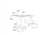
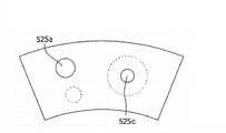
图1是示出安装有根据本发明的一个实施方式的触觉式方向盘开关设备的方向盘的示意性顶面图;1 is a schematic top view showing a steering wheel mounted with a tactile steering wheel switch device according to an embodiment of the present invention;
图2是示出根据本发明的一个实施方式的触觉式方向盘开关设备的示意性立体图;2 is a schematic perspective view illustrating a tactile steering wheel switch device according to an embodiment of the present invention;
图3是示出根据本发明的一个实施方式的触觉式方向盘开关设备的示意性顶面图;3 is a schematic top view showing a tactile steering wheel switch device according to an embodiment of the present invention;
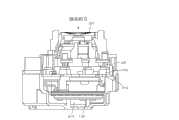
图4是示出根据本发明的一个实施方式的触觉式方向盘开关设备的示意性剖视图;4 is a schematic cross-sectional view illustrating a tactile steering wheel switch device according to an embodiment of the present invention;
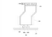
图5是示出根据本发明的一个实施方式的触觉式方向盘开关设备的触觉旋钮的示意性剖视图;5 is a schematic cross-sectional view illustrating a tactile knob of a tactile steering wheel switch device according to an embodiment of the present invention;
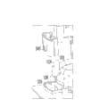
图6是示出根据本发明的一个实施方式的触觉式方向盘开关设备的示意性分解立体图;6 is a schematic exploded perspective view showing a tactile steering wheel switch device according to an embodiment of the present invention;
图7是示出根据本发明的一个实施方式的触觉式方向盘开关设备的按钮开关单元的示意性立体图;7 is a schematic perspective view showing a push button switch unit of a tactile steering wheel switch device according to an embodiment of the present invention;
图8是示出根据本发明的一个实施方式的触觉式方向盘开关设备的按钮开关单元的按钮引导部保持器和轮外壳主体的示意性局部放大立体图;8 is a schematic partial enlarged perspective view showing a button guide holder and a wheel housing main body of a button switch unit of a tactile steering wheel switch device according to an embodiment of the present invention;
图9是示出根据本发明的一个实施方式的触觉式方向盘开关设备的示意性局部放大分解立体图;9 is a schematic partial enlarged exploded perspective view showing a tactile steering wheel switch device according to an embodiment of the present invention;
图10是示出根据本发明的一个实施方式的触觉式方向盘开关设备的局部放大底部立体图;10 is a partially enlarged bottom perspective view illustrating a tactile steering wheel switch device according to an embodiment of the present invention;
图11是示出包括根据本发明的一个实施方式的触觉式方向盘开关设备的触觉式方向盘开关系统的示意性框图;11 is a schematic block diagram illustrating a tactile steering wheel switch system including a tactile steering wheel switch device according to an embodiment of the present invention;
图12是示出根据本发明的一个实施方式的触觉式方向盘开关设备的触觉旋钮的旋转操作的示意性立体图;12 is a schematic perspective view illustrating a rotational operation of a tactile knob of the tactile steering wheel switch device according to an embodiment of the present invention;
图13是示出根据本发明的一个实施方式的触觉式方向盘开关设备的按钮开关单元的操作的示意图;13 is a schematic diagram illustrating the operation of a button switch unit of a tactile steering wheel switch device according to an embodiment of the present invention;
图14是示出根据本发明的一个实施方式的触觉式方向盘开关设备的轴旋钮保持器的修改示例的示意性立体图;14 is a schematic perspective view showing a modified example of the shaft knob holder of the tactile steering wheel switch device according to one embodiment of the present invention;
图15是示出根据本发明的一个实施方式的触觉式方向盘开关设备的按钮开关单元的示意性局部放大立体图;15 is a schematic partially enlarged perspective view showing a push button switch unit of a tactile steering wheel switch device according to an embodiment of the present invention;
图16是示出根据本发明的一个实施方式的触觉式方向盘开关设备的按钮滤色器的按钮滤色器主体的示意性顶面图;16 is a schematic top view showing a button color filter main body of a button color filter of a tactile steering wheel switch device according to an embodiment of the present invention;
图17是示出根据本发明的一个实施方式的触觉式方向盘开关设备的按钮滤光器单元的按钮滤光器单元主体的示意性局部立体图;17 is a schematic partial perspective view showing a button filter unit main body of the button filter unit of the tactile steering wheel switch device according to an embodiment of the present invention;
图18是示意性示出按钮光源单元的状态的局部剖视图,该按钮光源单元使光穿过根据本发明的一个实施方式的触觉式方向盘开关设备的按钮滤光器单元来传递光;18 is a partial sectional view schematically showing a state of a button light source unit that transmits light through a button filter unit of the tactile steering wheel switch device according to an embodiment of the present invention;
图19是示出根据本发明的一个实施方式的触觉式方向盘开关设备的按钮光源单元的示意性侧剖视图;19 is a schematic side sectional view showing a button light source unit of a tactile steering wheel switch device according to an embodiment of the present invention;
图20和图21是示出根据本发明的一个实施方式的触觉式方向盘开关设备的按钮滤光器单元和按钮光源单元的操作状态的图示;20 and 21 are diagrams showing operational states of a button filter unit and a button light source unit of a tactile steering wheel switch device according to an embodiment of the present invention;
图22是示出根据本发明的一个实施方式的触觉式方向盘开关设备的按钮开关单元的另一个示例的示意性剖视图;和22 is a schematic sectional view showing another example of the push button switch unit of the tactile steering wheel switch device according to an embodiment of the present invention; and
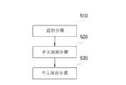
图23和图24是示出根据本发明的一个实施方式的触觉式方向盘开关设备的控制流程的流程图。23 and 24 are flowcharts showing a control flow of the tactile steering wheel switch device according to one embodiment of the present invention.
具体实施方式Detailed ways
现在,将在下文中结合附图更详细地描述根据本发明的优选实施方式的触觉式方向盘开关设备和包括该设备的触觉式方向盘开关系统。Now, a tactile steering wheel switch device and a tactile steering wheel switch system including the same according to preferred embodiments of the present invention will be described in more detail below with reference to the accompanying drawings.
根据本发明的一个实施方式的触觉式方向盘开关设备10安装在车辆的方向盘2上,以使得驾驶员更容易地操纵开关装置,触感被施加到驾驶员,并且执行物理警告功能,从而提高驾驶员的注意力和使用中的便利性。The tactile steering
车辆的方向盘2可包括轮缘2A与轮毂2B和2C。轮缘2A借助轮辐2C与轮毂主体2B相连。在该实施方式中,虽然轮缘被构造成环型,但其可以在使驾驶员能够形成用于操纵方向盘的接触区的范围内以多种方式被构造,但不限于此。A
触觉式方向盘开关设备10设置在轮毂主体2B上,但其可以以多种方式设置在一定范围内,在该范围内实施拇指轮式结构,以使得驾驶员能够简单而容易地操纵开关装置。The tactile steering
更具体而言,触觉式方向盘开关设备10包括触觉轮外壳单元100、电路板单元200和触觉轮装置300。电路板单元200和触觉轮装置300稳定地安装在触觉轮外壳单元100内。More specifically, the tactile steering
触觉轮外壳单元100稳定且牢固地设置在车辆方向盘2上,更具体而言,在该实施方式中设置在轮毂主体2B上。The tactile
触觉轮外壳单元10包括轮外壳罩110、轮外壳主体120和轮外壳基部130。轮外壳罩110、轮外壳主体120和轮外壳基部130彼此接合以限定容纳其它组成元件的内部空间。The tactile
轮外壳罩110中形成有通孔113,以使得随后将描述的触觉轮装置300穿过通孔113贯穿地设置在轮外壳罩110中。轮外壳罩110包括形成在其一个侧端处的轮外壳罩安装部111。轮外壳罩安装部111具有这样的结构,其中,该安装部与随后将描述的轮外壳主体120和/或轮外壳基部130接合。A through
按钮引导部115形成在轮外壳罩110的通孔113的内周缘上,使得随后将描述的按钮开关单元500的按钮510能稳定地竖直移动。A
轮外壳主体120设置成抵靠轮外壳罩110,并且包括通孔123。通孔123与通孔113相连以建立触觉轮装置300的稳定连接。轮外壳主体120包括在其外侧形成的轮外壳主体安装部121,以使得轮外壳主体安装部121与轮外壳罩安装部111接合,以确保轮外壳罩110和轮外壳主体120之间的稳定接合。The wheel housing
轮外壳主体120包括阻隔肋124,阻隔肋124以使得从通孔123的外周径向地延伸的方式形成在轮外壳主体120的上部上。阻隔肋124用来引导随后将描述的按钮510的稳定竖直移动。阻隔肋124可形成为多个。按钮通孔125形成在两个相邻的阻隔肋124之间,使得按钮开关单元500的至少部分组成元件能穿过按钮通孔125。按钮保持器引导部126形成在按钮通孔125的内表面上,以便引导随后将描述的按钮引导部保持器540的稳定竖直移动,并且防止按钮引导部保持器540和轮外壳主体120的错误组装。此外,在按钮通孔125的内表面上形成轮外壳主体止挡件127,使得可以通过随后将描述的按钮开关550等防止按钮510由于该按钮510的竖直恢复力而不期望地从按钮通孔125分离而脱离该按钮通孔。The wheel housing
轮外壳基部130设置成使轮外壳罩110与夹在轮外壳罩110和轮外壳基部130之间的轮外壳主体120相面对。轮外壳基部130包括在其外周上形成的轮外壳基部安装部131,以使得其与轮外壳罩安装部111接合,从而确保轮外壳罩110和轮外壳基部130之间的稳定接合。The
轮外壳基部连接器132设置在轮外壳基部130上,并且连接到随后将描述的电路板单元200的板连接器引脚211设置在轮外壳基部连接器132中,以与外部电气装置建立电连接。在本文中,虽然用附图标记200表示的元件被称为电路板单元,但其可以在形成电路布线的范围内实施为典型的印刷电路板或插入成型结构。此外,电路板单元200可以在实现电信号的传输的范围内以多种方式构造,例如形成为用于向外部释放从LED等产生的热量的金属板。A wheel
电路板单元200设置在触觉轮外壳单元100内部。电路板单元200可形成为单个板,但在该实施方式中,采用具有多个板的结构。印刷电路板200与另一个元件,特别是随后将描述的触觉轮装置300电连接,以使得可以建立向触觉轮装置致动器310的触觉轴施加旋转力或感测触觉轴的旋转状态的电信号的传输。The
电路板单元200包括主板210、感测板220、柔性板230和旋钮板240。主板210设置在轮外壳主体120和轮外壳基部130之间,并且连接器引脚211设置在主板210上以与外部电气装置建立电连接。主板210具有形成在其中心的通孔213,以使得另一个元件(即触觉轮装置致动器310)可穿过通孔213贯穿地设置在主板210内。The
随后将描述的触觉轮装置300的触觉轮装置感测单元330的元件设置在感测板220上。感测板220竖直地设置在主板210上。这是本发明的一个实施方式的示例,并且感测板的布置结构不限于此,而是可以对感测板进行各种修改,所述修改包括与主板一体化到一起。在该实施方式中,感测板220固定地安装在触觉轮装置300的触觉轮装置固定器320的固定器基部323上,以实施竖直地设置在主体210上的结构。The elements of the tactile wheel
柔性板230在两端分别连接到相对于彼此竖直地定向的主板210和感测板220,以在主板210和感测板220之间建立平稳的电连接。在该实施方式中,虽然主板210和感测板220借助柔性板230彼此相连,但可以实施主板210和感测板220彼此直接相连的结构。The
旋钮板240设置在随后将描述的触觉轮装置300的触觉轮装置致动器310的顶部上。触觉旋钮光源单元340设置在旋钮板240上,以使得借由触觉旋钮301的光输出功能可由触觉旋钮光源单元340执行。The
触觉轮装置300设置在触觉轮外壳单元100内。触觉轮装置300包括触觉轮装置致动器310、触觉轮装置固定器320和触觉轮装置感测单元330。触觉轮装置致动器310与电路板单元200建立电连接,使得其从内部控制单元/外部控制单元接收电信号,以便产生预定的旋转力、冲击力或旋转抑制力,并且响应于操纵者转动或旋转触觉旋钮的状态根据通过电连接的电信号预先存储在存储单元中的方案或以用于警告车辆状态的某种预定的已存储方式为操纵者提供内力感觉。在该实施方式中,触觉轮装置致动器310实施为电动马达。根据该实施方式的触觉轮装置致动器310形成为双轴电动马达。术语“双轴”是指其中旋转轴连接到触觉轮装置致动器的两端的结构。触觉旋钮301和触觉轮装置感测单元330分别连接到实施为双轴电动马达的触觉轮装置致动器310的触觉轴311和313。触觉轴311和313设置在触觉轮装置致动器310的两端上,并且包括第一末端311和第二末端313。第一末端311连接到触觉旋钮301,并且第二末端313连接到随后将描述的触觉轮装置感测单元330。The
触觉轮装置致动器310借助于触觉轮装置固定器320稳定地设置在触觉轮外壳单元100内,并且与随后将描述的按压开关单元400的按压开关操作部420一起进行稳定的竖直移动。触觉轮装置固定器320包括固定器主体321和固定器基部323。固定器主体321具有形成在其上端的通孔326,并且具有形成在其下端的通孔324。构造为双轴电动马达的触觉轮装置致动器310的触觉轴311和313分别穿过固定器主体通孔326和固定器基部通孔324贯穿地设置在触觉轮装置致动器310的上端和下端内。固定器安装部分别设置在固定器主体321和固定器基部323的外周上,并且诸如螺栓的固定器紧固构件328穿过固定器安装部安装在固定器主体321和固定器基部323上,使得固定器主体321和固定器基部323可牢牢地彼此紧固。The tactile
固定器主体321具有形成在其上端上的旋钮板安放部327,以使得电路板单元200的旋钮板240可安放在旋钮板安放部327上以实现稳定的固定状态。固定器基部感测安装部325形成在固定器基部323的一侧并且实现触觉轮装置感测单元330的可旋转副带轮轴336的稳定安装状态。The
触觉旋钮301与触觉轴311相连,并且暴露地设置在触觉轮外壳单元100的一个表面上。触觉旋钮301与触觉轮装置致动器310的触觉轴311相连,并且轴旋钮保持器312可设置在触觉旋钮301和触觉轴311之间。轴旋钮保持器312夹在触觉旋钮301与触觉轴311和313的第一末端311之间,从而通过轴旋钮保持器312可以防止触觉旋钮301与触觉轴311和313的第一末端的不期望的相对旋转。The
轴旋钮保持器312和第一末端311采取压配合构造。轴旋钮保持器312的外周可具有防止接触区域之间的相对旋转的倒角的多边形结构。此外,轴旋钮保持器312不限于此,而是在具有防止触觉旋钮和触觉轮装置致动器的触觉轴之间的相对旋转的结构的范围内,可以以多种方式被构造,例如借助诸如单独的旋钮螺钉等的紧固装置实现第一末端和轴旋钮保持器之间的接合状态。The
触觉旋钮301包括触觉旋钮板301a和触觉旋钮主体301b。触觉旋钮主体301b具有形成在其下部的凹部301c,以便轴旋钮保持器312可以容纳在凹部301c中。触觉旋钮板301a设置在触觉旋钮主体301b的一个表面上。触觉旋钮主体301b和触觉旋钮板301a可以彼此一体地形成。触觉旋钮抓握部301-2形成在触觉旋钮板301a的一个表面上,使得使用者可执行触觉旋钮301的平稳旋转操作,即围绕触觉轮装置致动器310的触觉轴311和313平稳的旋转操作而无任何打滑。The
此外,在触觉旋钮301的一个表面上形成触觉旋钮凹陷301-1。触觉旋钮凹陷301-1形成为凹入形状,并且采取这样的结构,即:该触觉旋钮凹陷沿触觉旋钮301的旋转轴的方向的深度朝向触觉旋钮的中心区域逐渐增加。也就是说,触觉旋钮凹陷301-1具有这样的结构:沿垂直于触觉旋钮301的旋转中心的方向形成的凹陷深度d1和d2,从触觉旋钮301的中心沿径向方向逐渐减小。也就是说,如图5所示,触觉旋钮凹陷301-1的在触觉旋钮301的中心区域处的深度d1被设为远大于触觉旋钮凹陷301-1的在触觉旋钮301的周缘区域处的深度d2,使得驾驶员能使用他或她的手指(特别是他或她的拇指)对触觉旋钮301进行更平稳的旋转操作。In addition, a tactile knob recess 301 - 1 is formed on one surface of the
借助于该结构,驾驶员能实现手指和触觉旋钮301之间的轻松接触状态,以便在操纵方向盘2的同时,在使用他或她的手指例如拇指对触觉旋钮301进行旋转操作时执行对触觉旋钮301的平稳旋转操作。换句话讲,在触觉旋钮301具有其中未形成触觉旋钮凹陷或触觉旋钮凹陷中凸地形成半球形状的结构的情况下,驾驶员难以通过他或她按压触觉旋钮301的顶部表面而对触觉旋钮进行平稳的旋转操作。相反,在触觉旋钮301形成有如上构造的触觉旋钮凹陷的情况下,驾驶员能通过他或她按压触觉旋钮301的顶部表面,尤其是通过他或她抓握方向盘的轮缘而对触觉旋钮进行更平稳的旋转操作。With this structure, the driver can achieve a state of easy contact between the fingers and the
此外,触觉旋钮301可包括用于允许驾驶员执行平稳的旋转操作的元件。也就是说,触觉旋钮抓握部301-2突出地形成在触觉旋钮301的一个表面上。借助于触觉旋钮抓握部301-2的构造,当驾驶员使用他或她的手指例如拇指对触觉旋钮310进行旋转操作时,他或她能保持平稳的旋转状态而没有任何打滑。In addition, the
触觉旋钮301可形成为单体,但也可具有双料注射结构,以在必要时允许驾驶员借助触觉旋钮30对触觉开关装置进行更平稳的操纵。也就是说,触觉旋钮301可具有这样的结构,其中,在触觉旋钮301的表面上形成触觉旋钮接触表面301-3,该接触表面由在接触驾驶员的手指等的皮肤时具有较小可能打滑的材料制成,以便增加驾驶员的手指和触觉旋钮之间的接触摩擦力。例如,触觉旋钮301可具有这样的结构,其中,由附图标记301-4表示的部分主要由诸如聚碳酸酯(PC)的材料形成,并且由诸如聚氨酯等的双料注射热塑性弹性体形成的触觉旋钮接触表面301-3另外地形成在部分301-4的一个表面上。在这种情况下,当驾驶员操纵触觉旋钮时,可防止由于他或她的手指上出现的汗水而导致的打滑,以便进行平稳的旋转操作。The
触觉轮装置感测单元330与触觉轴311和313的第二末端313相连以检测触觉轴的旋转状态,即触觉轮装置致动器310的操作状态。触觉轮装置致动器的第二末端与触觉轮装置感测单元330相连。为了防止触觉轮装置致动器310和触觉轮装置感测单元330之间的相对旋转,而在触觉轮装置致动器310的触觉轴的第二末端和触觉轮装置感测单元330之间设置轴感测保持器314。轴感测保持器314是与用于在第一末端和触觉旋钮之间连接的轴旋钮保持器312相对应的元件。轴感测保持器314的形状和结构与轴旋钮保持器312的形状和结构相同,因此其详细描述将用轴旋钮保持器312的上述描述代替。The tactile wheel
触觉轮装置感测单元330在该实施方式中实施为光检测器。触觉轮装置感测单元330包括装置感测主体部330a和装置检测传感器部339。装置感测主体部330a与触觉轮装置致动器310相连以输出触觉轴的旋转状态,并且装置检测传感器部339检测装置感测主体部330a的旋转状态。在该实施方式中,虽然装置感测主体部被构造为用于机械传递触觉轴的旋转状态的结构,并且装置检测传感器部实施为用于检测装置感测主体部的旋转的光传感器,但可以实施其中装置感测主体部包括磁体并且装置检测传感器部包括磁性传感器的构造。该实施方式的装置感测主体部330a包括装置感测主带轮331、装置感测副带轮335、装置感测带333和装置狭槽337。装置感测主带轮331以使得该装置感测主带轮331和轴感测保持器314之间的相对旋转被限制的方式与轴感测保持器314相连,从而使该装置感测主带轮331与触觉轴的第二末端313一起旋转。装置感测主带轮331具有形成在其中心的主带轮安装孔332(参见图9),以使得轴感测保持器314被插入和容纳在主带轮安装孔332中。在装置感测主带轮331的下端处设置有轴惯性主体315,轴惯性主体315充当用于通过装置感测主带轮331实现触觉轴的稳定操作并产生准确的内力感觉的组成元件。轴惯性主体315被构造为环形,使得其贴合地设置在装置感测主带轮331的主带轮安装孔332的外周周围。如果需要,轴惯性主体315和装置感测主带轮331可彼此一体地形成,但根据该实施方式的轴惯性主体形成为单独的元件,从而其借助诸如螺栓的紧固构件而牢固地安装到装置感测主带轮315的下端。The tactile wheel
装置感测副带轮335与装置感测主带轮331相连而与从该装置感测主带轮331间隔开,并且装置感测带333将装置感测主带轮331和装置感测副带轮335互连,以将装置感测主带轮331的机械旋转状态传递给装置感测副带轮335。装置狭槽(slot)337具有同轴地连接到装置感测副带轮335的结构,并且当装置感测副带轮335旋转时与装置感测副带轮335一起旋转。装置狭槽337由副带轮轴336以可旋转的方式支撑。副带轮轴336以可旋转的方式安装到触觉轮装置固定器320的固定器基部323。在这种情况下,副带轮轴336插入地设置在固定器基部323的固定器基部感测安装部325内。装置感测副带轮335和装置狭槽337安装到副带轮轴336。在副带轮轴336和装置感测副带轮335之间可进一步设有副带轮衬套338,以便实现固定器基部323和装置感测副带轮335之间的平稳旋转。装置检测传感器部339设置在感测板220上,而与装置狭槽337相邻。装置检测传感器部339实施为光传感器。装置狭槽337设置在发光部分和装置检测传感器部339的光接收部分之间,以便由装置检测传感器部将触觉轴的第二末端的旋转状态经由装置感测主带轮、装置感测带、装置感测副带轮和装置狭槽转化为光信号,以允许装置检测传感器部分输出电信号的变化。这种电信号的变化可通过设置在轮外壳基部连接器132中的连接器引脚传送到内部或外部电气装置。The device sensing
在该实施方式中,装置感测主带轮331与装置感测副带轮335的旋转比优选地具有大于1的值。在通过驾驶员的手指操纵的触觉旋钮301旋转一次,即连接到触觉旋钮301且进行同轴旋转的装置感测主带轮331旋转一次时,装置感测副带轮335旋转几次,从而能最终增加通过装置检测传感器部分339对于触觉旋钮301的一次旋转的分辨力,以实现对触觉旋钮301和触觉轴的更准确的检测。In this embodiment, the rotation ratio of the device sensing
在上述实施方式中,虽然已经描述了触觉轮装置感测单元采用带轮/带结构,但其可以在感测触觉旋钮或触觉轴的准确旋转状态的范围内以多种方式构造,例如采用齿轮传动结构。在触觉轮装置感测单元采用齿轮传动结构的情况下,触觉轴侧的齿轮和其中设置触觉轮装置感测单元的装置狭槽的齿轮可直接彼此相连,并且如果需要,可以在这些齿轮之间相连地设置不止一个惰轮。此外,在上述实施方式中,虽然触觉轮装置感测单元实施为光传感器结构,但其可以在感测触觉旋钮的旋转状态的范围内以多种方式构造。In the above embodiments, although it has been described that the sensing unit of the tactile wheel device adopts a pulley/belt structure, it can be configured in various ways within the range of sensing the exact rotational state of the tactile knob or tactile shaft, such as using gears transmission structure. In the case that the sensing unit of the tactile wheel device adopts a gear transmission structure, the gear on the side of the tactile shaft and the gear of the device slot in which the sensing unit of the tactile wheel device is arranged can be directly connected to each other, and if necessary, can be placed between these gears More than one idler gear is provided contiguously. Also, in the above-described embodiments, although the tactile wheel device sensing unit is implemented as a photosensor structure, it may be configured in various ways within the range of sensing the rotational state of the tactile knob.
借助于触觉旋钮、触觉轮装置致动器和触觉轮装置感测单元的构造,涉及操纵者意图的操纵状态经由触觉旋钮被触觉轮装置感测单元检测,并且将从实施为双轴马达的触觉轮装置致动器产生的预定内力感觉信号通过触觉旋钮以从内部电气装置或外部电气装置传递的预定方式施加到操纵者,以响应于由触觉轮装置感测单元检测的操纵状态实施诸如警告等的操作,或者以预定方式施加,使得操纵者能实现更稳定而准确的触觉感知。触觉旋钮301以使得触觉旋钮301围绕充当中心轴线的触觉轴进行旋转运动的方式实现布置有车辆方向盘2的大致平面上的旋转操作。借助于旋转操作,使用者可借助车辆方向盘2的轮缘2A保持操纵状态,并且同时可实施使得通过他或她的拇指能够操纵触觉式方向盘开关设备10的拇指轮式操作。这可以增强诸如通过触觉旋钮平稳选择预设菜单的操纵功能,甚至通过取消不得不使驾驶员的手离开方向盘(更具体地为轮缘)以操纵开关的操作而不会在抓握轮缘的状态下转移驾驶员的驾驶注意力。例如,在通过将执行往复操作(seesaw operation)或围绕铰接点滚动操作(scroll operation)的常规结构与显示装置相关联而实施用于在屏幕上显示预定选择菜单的装置的过程中,伴随着问题,因为驾驶员难以在进行预定菜单选择时控制选择操纵,因而容易错过他或她想要选择的菜单。另一方面,在拇指轮驱动类型的触觉式方向盘开关设备的情况下,伴随着优点,因为驾驶员能够通过驾驶员的拇指在顺时针或逆时针方向上的旋转操作而快速且准确地选择他或她想要的菜单,从而实现内力感觉的更平稳提供。此外,也可以多种方式形成与触觉式方向盘开关设备的旋转操作相关联的用户界面。By virtue of the configuration of the tactile knob, the tactile wheel device actuator and the tactile wheel device sensing unit, the manipulation state related to the operator's intention is detected by the tactile wheel device sensing unit via the tactile knob, and is transferred from the tactile sensor implemented as a two-axis motor. A predetermined internal force sensory signal generated by the wheel device actuator is applied to the operator through the tactile knob in a predetermined manner transmitted from the internal electric device or the external electric device to implement such as a warning etc. in response to the manipulation state detected by the tactile wheel device sensing unit The operation, or applied in a predetermined way, enables the operator to achieve a more stable and accurate tactile perception. The
同时,根据本发明的触觉式方向盘开关设备借助触觉旋钮能够进行按压操作,即沿垂直于布置有车辆方向盘的平面的纵向的竖直移动。借助于这样的结构,本发明的触觉式方向盘开关设备能基于拇指轮驱动方法通过平稳的触觉旋转操作和按压操作实施各种操作。触觉式方向盘开关设备还可包括按压开关单元400,用于通过触觉式方向盘开关设备的竖直移动而输出切换信号的变化。按压开关单元400包括按压开关410和按压开关操作部420。按压开关410设置在电路板单元200的主板210的一个表面上。虽然按压开关410在该实施方式中实施为竖直地操作的轻触开关,但其在执行按压操作的范围内可以以多种方式构造,例如实施为金属弹片开关。按压开关操作部420与触觉轮装置致动器310一起竖直移动以开启或关闭按压开关410。按压开关操作部420包括按压开关操作主体421和按压开关操作凸起423。按压开关操作主体421具有环形结构。按压开关操作主体421具有形成在其中心的通孔422,从而设置在触觉轮装置致动器310的外周上的触觉轮装置固定器320贯穿地设置在通孔422中。按压开关安装部424形成在按压开关操作主体421的通孔422的内周面上,并且固定器主体按压开关安装部322形成在触觉轮装置固定器320的外周面上以对应于按压开关安装部424。因此,按压开关安装部424与固定器主体按压开关安装部322接合,使得按压开关操作主体421和触觉轮装置固定器320可稳定地彼此组装在一起并可保持在安装状态。此外,按压开关操作部420可具有这样的结构,其中,紧固元件设置在按压开关操作主体421的外周面上,使得按压开关操作主体和触觉轮装置固定器在固定器主体与固定器基部接合时可以彼此紧固。Meanwhile, the tactile steering wheel switch device according to the present invention enables a push operation, that is, a vertical movement in a longitudinal direction perpendicular to a plane on which the vehicle steering wheel is arranged, by means of the tactile knob. With such a structure, the tactile steering wheel switch device of the present invention can perform various operations through smooth tactile rotation operation and push operation based on the thumb wheel driving method. The tactile steering wheel switch device may further include a
按压开关操作凸起423设置在按压开关操作主体421的外周上,使得其可以建立与按压开关410的直接接触,可以恒定地保持在其中按压开关操作凸起423、按压开关操作主体421、触觉轮装置固定器320、触觉轮装置致动器310和触觉旋钮301通过按压开关410的初始支撑状态顺序地连接的结构的支撑状态,并且在将大于施加到按压开关410的力的外力施加到触觉旋钮301上时可以建立预定的竖直移动状态。The push
在本发明的一个实施方式中,按压开关410以多个数量提供。按压开关操作凸起423也以多个数量提供以对应于多个按压开关410。在该实施方式中,借助于数量均为四个的按压开关410和按压开关操作凸起423,触觉轮装置致动器310和触觉旋钮301可通过按压开关410建立稳定的支撑状态。In one embodiment of the present invention, push switches 410 are provided in multiple quantities. The push
在当外力不施加到触觉旋钮上时的正常情况下,触觉轮装置致动器310通过按压开关410建立稳定的竖直支撑状态。另一方面,当诸如驾驶员的使用者以大于预设值的力竖直地按压触觉旋钮301时,经由触觉旋钮301、触觉轮装置致动器310、触觉轮装置固定器320和按压开关操作部420使按压开关410的电信号发生变化。在该实施方式中,按压开关410的数量提供为四个,并且可以根据触觉旋钮301的按压方向而实施单独的切换操作。例如,可以实施倾斜操作,其中,当使用者按压触觉旋钮301的右上端时,只有某个区域受压,从而使触觉轮装置致动器310仅在其一侧端向下移动。另一方面,在使触觉旋钮301的中心区域保持水平状态所情况下当使用者竖直地按压与触觉轮装置致动器310相连的触觉旋钮301时,实现完全竖直的按压操作,从而可以从四个按压开关产生信号。可以实施这样的结构:当相对于触觉旋钮301的中心(即触觉轮装置致动器310的中心轴线)对角地设置的按压开关在一定时间内被同时或连续地按压时,这被看作是完全竖直的按压操作,而不是各个单独的倾斜操作。In a normal situation when no external force is applied to the tactile knob, the tactile
同时,按压开关单元400可具有这样的结构:按压开关410牢固地设置在主板210上,并且在触觉轮装置感测单元330与触觉轮装置致动器310一起竖直地移动时,只有按压开关操作部420与触觉轮装置致动器一起竖直地移动。感测板220牢固地设置在触觉轮装置固定器320的设置有触觉轮装置致动器310的固定器基部323上,并且装置感测主体部的装置感测主带轮连接到触觉轴且装置感测副带轮连接到固定器基部,使得装置检测传感器部分和装置感测主体部分建立其中两者最终与触觉轮装置一起竖直地移动的结构。借助于该结构,实施按压操作的按压开关单元与实施旋转操作的触觉轮装置之间的连接最终通过触觉旋钮进行,从而可以通过竖直按压操作和旋转操作的整合赋予诸如驾驶员的操纵者优良的操纵感觉,并且可以实施多样化的操作,例如同时实现稳定的倾斜功能。Meanwhile, the
触觉式方向盘开关设备还可包括这样的构造,该构造能通过在实施旋转操作和按压/倾斜操作以及执行各个功能时借助光的输出而改善视觉。本发明的触觉轮装置300可包括触觉旋钮光源单元340。触觉旋钮光源单元340(参见图15)设置在电路板单元200的旋钮板240上。旋钮板240设置在触觉轮装置致动器310的顶端上,使得触觉轴311的第一末端311贯穿地设置在触觉轮装置致动器310的端部处。更具体而言,旋钮板安放部327形成在固定器主体321的上端上,以便将旋钮板240安放在旋钮板安放部327中(参见图5)。在这种情况下,旋钮板240可通过单独的线与主板210建立电连接。触觉旋钮光源单元340设置在旋钮板240的一个表面上并且实施为LED。触觉旋钮301由诸如聚碳酸酯(PC)的透光材料形成,使得离开旋钮板240上的触觉旋钮光源单元340的光能顺利地传输到外部。触觉旋钮光源单元340可以多个数量提供。根据本发明的触觉旋钮光源单元340被构造成使得发出蓝色、绿色和红色光的LED等角度地布置在旋钮板240上,或者以多个数量布置为一体化模块以输出多色。从实施为LED的触觉旋钮光源单元340发出的光透射和/或引导穿过触觉旋钮主体301b的底部表面并输出到外部。触觉旋钮光源单元340被操作成使得各种颜色、尺寸和周期的光以预定的可控方式被输出到外部,例如,在预定时间段内周期性地以预定方式闪烁光,在不断地变化的信号周期内输出光,或同时地输出给定的颜色以输出组合颜色,使得诸如驾驶员的使用者能在视觉上快速地感知触觉式方向盘开关设备的操作状态或由使用者选择的操纵状态。The tactile steering wheel switch device may also include a configuration capable of improving vision by outputting light when rotating operations and pressing/tilting operations are performed and various functions are performed. The
同时,根据本发明的触觉式方向盘开关设备10包括按钮开关单元500,使得按钮开关单元和触觉轮装置能执行组合的操纵功能。按钮开关单元500设置在触觉旋钮301的外部。在这种情况下,按钮开关单元500可通过触觉旋钮301实现独立于触觉轮装置致动器或按压开关单元的单独的竖直操作,以产生某些变化的切换信号。Meanwhile, the tactile steering
根据本发明的实施方式的按钮开关单元500被构造成围绕触觉旋钮301的外周缘。按钮开关单元500包括按钮510、按钮引导部530、按钮引导部保持器540和按钮开关550。按钮510设置在触觉旋钮301的外部,使得在其一个表面处暴露于触觉轮外壳单元100的外部。按钮510包括头部511和主体513。按钮头部511暴露地设置在触觉旋钮301的外部,并且按钮主体513设置在按钮头部511的下端。虽然在该实施方式中按钮头部511和按钮主体513彼此一体地形成,但它们可以彼此单独地形成。The push button switch unit 500 according to the embodiment of the present invention is configured to surround the outer periphery of the
按钮图标512可显示在按钮头部511的一个表面上,并且可以直接形成在按钮头部511的一个表面上。按钮头部511可具有这样的结构,其中,如果需要,其由诸如聚碳酸酯的透明材料形成,从而通过单独的显示装置输出按钮图标。The
按钮头部511和按钮主体513被构造成在两者之间限定内部空间,从而能将按钮引导部530设置在该内部空间中。按钮引导部530在其一端处设置在按钮510内,并且在其另一端处朝向电路板单元200设置在触觉轮外壳单元100内。也就是说,按钮引导部530以在其另一端朝向主板210定向的方式设置在按钮头部511和按钮主体513之间限定的内部空间中。按钮引导部530包括头部531和主体533。虽然在该实施方式中按钮引导部头部531和按钮引导部主体533彼此一体地形成,但它们可以彼此分离地形成。按钮引导部主体533连接到按钮引导部头部531的一端,并且按钮引导部头部531的顶端以插入的方式设置在按钮头部511和按钮主体513之间限定的内部空间中。按钮引导部主体533的底端以朝向主板210定向的方式设置在按钮引导部保持器540内。按钮引导部530由透明或彩色导光材料形成,从而将通过按钮引导部主体533的末端进入按钮引导部530的光通过按钮引导部主体533的一个表面传输到外部。在按钮引导部主体533的一侧形成凸安装部535,并且在按钮引导部保持器540的一侧形成凹安装部544以对应于凸安装部535,使得凸安装部535和凹安装部544彼此贴合地接合。按钮引导部主体533包括形成在其外周面上的凹槽534,使得凹槽534与形成在按钮引导部保持器540上的保持器接纳槽542接合,以在按钮引导部530和按钮引导部保持器540之间建立平稳的相对安装结构,从而能避免在平稳安装和组装触觉轮外壳单元100时错误组装的可能性。The
按钮引导部保持器540附接到按钮引导部530,并且以可与按钮引导部530一起竖直地稳定移动的方式设置在触觉轮外壳单元100中,更具体而言,设置在轮外壳主体120中。按钮引导部保持器540以可竖直运动的方式插入轮外壳主体120的一个表面上形成的按钮通孔125内。按钮引导部保持器540具有沿其纵向形成在其外表面上的按钮引导部保持器线546。在按钮通孔125的内表面上形成按钮保持器引导部126以对应于按钮引导部保持器线546,使得按钮引导部保持器线546和按钮保持器引导部126能以可竖直运动的方式彼此接合。The
按钮引导部保持器540包括按钮引导部保持器操作部543,该按钮引导部保持器操作部543从形成在按钮引导部保持器540的中心的按钮引导部保持器容纳部541的内表面的下端向下延伸,使得按钮引导部保持器操作部543能与设置在按钮引导部保持器下方的按钮开关550保持恒定的接触状态。也就是说,按钮引导部保持器540、按钮引导部530和按钮510可具有它们由单独的支撑装置支撑的结构,但在该实施方式中具有它们由按钮开关550顺序地支撑的结构。The
借助于这样的结构,由诸如驾驶员的使用者施加到按钮510的压力通过按钮引导部保持器540传递到按钮开关550。在这种情况下,按钮引导部保持器操作部543具有这样的结构:该按钮引导部保持器操作部543从按钮引导部保持器容纳部541的内表面向下延伸从而朝向底部定向。按钮引导部保持器操作部543具有形成在其顶部表面上的安放面547,以建立按钮引导部主体保持部536的安放状态。也就是说,按钮引导部530具有形成在其下端的两个按钮分支537和形成在其中心的按钮引导部主体保持部536,使得按钮引导部主体保持部536与按钮引导部保持器操作部安放面547紧密接触以实现稳定的安装结构。按钮引导部分支537从按钮引导部主体530的下端分支以实现其中从设置在按钮开关550的两侧的一对按钮光源单元560发出的光能传输至顶部的结构。按钮光源单元560实施为LED等。按钮光源单元560可相对于每个按钮引导部设置成多个,以实现其中按钮光源单元560被单独地分配到一对按钮引导部分支的结构。按钮引导部530可由诸如聚碳酸酯的透明导光材料形成或者可具有带有预定颜色的结构。With such a structure, pressure applied to the
此外,按钮开关单元500还可包括显示装置,该显示装置能使用离开按钮光源单元的光形成各种图标。同时,按钮光源单元具有这样的结构,该结构相对于每个按钮引导部或每个按钮滤光器单元输出具有多种颜色的光。按钮开关单元500还可包括按钮滤光器单元520。按钮滤光器单元520包括按钮滤光器单元基部521和按钮滤光器单元主体523。按钮滤光器单元基部521形成为用于均匀地分散通过按钮滤光器单元基部521的底部表面进入的光的导光材料。按钮滤光器单元主体523包括:第一透射区523a,该第一透射区523a允许第一颜色光离开输出具有多种颜色的光的按钮光源单元;第二透射区523b,该第二透射区523b允许不同于第一颜色光的第二颜色光离开按钮光源单元;相交区523c,第一透射区和第二透射区在该相交区523c处彼此相交;和阻挡区523d,该阻挡区523d阻挡第一颜色光和第二颜色光。相交区523c可与第一透射区523a和第二透射区523b一起形成第一按钮图标512a和第二按钮图标512b。例如,按钮光源单元可包括红色LED和蓝色LED。第一透射区允许红光离开,并且第二透射区允许蓝光离开,以便能穿过第一透射区、第二透射区、相交区等显示诸如“USER SET”或的预定图标。In addition, the button switch unit 500 may further include a display device capable of forming various icons using light exiting the button light source unit. Meanwhile, the button light source unit has a structure that outputs light having a plurality of colors with respect to each button guide or each button filter unit. The button switch unit 500 may further include a
此外,根据本发明的触觉式方向盘开关设备可以实施为与其它组成元件形成一体。也就是说,触觉式方向盘开关设备10连接到:触觉轮装置致动器310,该触觉轮装置致动器310在通过触觉旋钮301实现旋转操作的过程中提供内力感觉;触觉轮装置感测单元330,该触觉轮装置感测单元330感测触觉轮装置致动器310的旋转运动状态;按压开关单元400,该按压开关单元400通过触觉旋钮301和触觉轮装置致动器310的竖直移动实现按压操作;以及按钮开关单元500,该按钮开关单元500设置在触觉旋钮301的外部。触觉式方向盘开关设备10将电信号传递到组成元件并且从组成元件接收电信号。Furthermore, the tactile steering wheel switch device according to the present invention may be implemented to be integrated with other constituent elements. That is, the tactile steering
此外,触觉式方向盘开关设备10可以被构造成具有控制单元20和与控制单元20相连的存储单元30,或者可以实施为还包括算术逻辑单元40。控制单元与电路板单元200建立电连接并且连接到触觉轮装置单元以及按钮开关单元和按压开关单元中的任一者,并且存储单元30与控制单元20建立电连接并且存储用于预定操作模式的预定数据。也就是说,存储单元30包括用于按照操作模式生成电信号以在驾驶员操纵触觉旋钮的拇指轮时提供内力感觉的数据等。算术逻辑单元40电连接到控制单元20和存储单元30并且根据控制单元20的算术控制信号来执行预定操作模式所需的算术逻辑处理。控制单元20、存储单元30和算术逻辑单元40可以依照设计规格被构造为各种形式,例如,嵌入在触觉式方向盘开关设备10中或者作为单独的元件构造成设置在触觉式方向盘开关设备10外部的结构。Furthermore, the tactile steering
从触觉式方向盘开关设备10的开关单元输入的信号被传递到触觉式方向盘开关设备10的控制单元20。控制单元20通过由算术逻辑单元40执行的特定算术逻辑处理而产生预定的控制信号,并且基于用于希望通过例如触觉式方向盘开关设备选择、操纵和操作的操作单元的预定操作模式的预定数据以及从触觉式方向盘开关设备10的开关单元输入的信号将所述预定控制信号施加到输出单元,所述预定操作模式例如为空调设备的操作温度控制模式、用于诸如目的地选择或路线搜索的导航操作的导航模式,等等。预定数据存储在与控制单元20建立电连接的存储单元30中。包括在触觉式方向盘开关设备10中的触觉轮装置致动器310可以被包括作为输出单元。此外,用于显示图像的分离显示单元50和/或用于输出声音的音频输出单元60可以被包括作为输出单元。此外,可以将从控制单元20接收的控制信号直接施加到作为待被直接控制的对象的目标操作单元70,例如,诸如车辆的空调设备和导航器之类的操作单元。A signal input from the switch unit of the tactile steering
同时,根据本发明的一个实施方式的按钮开关单元可以具有如下结构:该结构设置在实施拇指轮操作的触觉旋钮的外部并且独立地沿竖直方向操作。虽然在该实施方式中按钮开关单元被实施为物理操作轻触开关,但是根据本发明的按钮开关单元可以具有实施非接触型触点结构的结构。在该实施方式中,类似的附图标记和名称表示类似的部件。如图22中所示,根据本发明的按钮开关单元500包括:按钮510、按钮引导部530、按钮引导部保持器540和按钮开关550a。按钮510设置在触觉旋钮301的外部,使得该按钮的一个表面暴露于触觉轮外壳单元100的外部,并且按钮引导部530的设置成使得其一端设置在按钮510内部而另一端朝向电路板单元200设置在触觉轮外壳单元100内部。按钮引导部530优选地由透明的导光材料形成。按钮引导部保持器540附接于按钮引导部530并且稳定地设置在触觉轮外壳单元100中,更具体而言,稳定地设置在轮外壳主体120中,以与按钮引导部530一起竖直移动。如上所述按钮引导部保持器540以竖直可动的方式插入轮外壳主体120的一个表面上形成的按钮通孔125中。按钮引导部保持器操作部543设置在按钮引导部保持器540中,并且按钮引导部保持器操作部543形成为从形成于按钮引导部保持器540的中央的按钮引导部保持器容纳部541的内表面的下端延伸,并且设置成面对按钮开关磁性传感器553并与该按钮开关磁性传感器553分隔开,该按钮开关磁性传感器553实施为设置在下部的磁性传感器,诸如,霍尔传感器(Hall sensor)。Meanwhile, the push button switch unit according to one embodiment of the present invention may have a structure that is provided outside the tactile knob performing thumbwheel operation and independently operated in a vertical direction. Although the push button switch unit is implemented as a physically operated tact switch in this embodiment, the push button switch unit according to the present invention may have a structure implementing a non-contact type contact structure. In this embodiment, like reference numerals and names refer to like components. As shown in FIG. 22, the button switch unit 500 according to the present invention includes: a
按钮开关550a包括按钮开关磁性传感器553、按钮开关磁体551和按钮开关弹性单元555。如上所述,按钮开关磁性传感器553设置成面对电路板单元200的一个表面上的按钮引导部保持器540。按钮开关磁体551设置在按钮引导部保持器540中,并且在按钮引导保持部540的一端形成用于容纳按钮开关磁体551的空间。此外,按钮开关弹性单元555实施为卷簧,并且按钮开关弹性单元555的一端接触按钮引导部或按钮引导部保持器的一端,并且按钮开关弹性单元555的另一端由电路板单元等支撑并且与按钮引导部或按钮引导部保持器相连,以在向按钮施压之后保持回复到初始位置。也就是说,按钮开关磁性传感器553设置在电路板单元上,并且按钮开关弹性单元555的另一端设置在按钮开关磁性传感器553的外周上。按钮开关弹性单元555可以由组成元件形成,该组成元件构成非金属材料的弹性行为,以防止按钮开关磁性传感器553产生信号误差。The button switch 550 a includes a button switch magnetic sensor 553 , a button switch magnet 551 and a button switch elastic unit 555 . As described above, the button switch magnetic sensor 553 is provided to face the
此外,可以如图17至图21所示地构造以上实施方式中描述的按钮光源单元和按钮滤光器单元。如果设置数量为多个的按钮光源单元560,则可以采用提供多个桥的构造,以将从按钮光源单元输出的光稳定地传递到按钮滤光器单元。也就是说,如图18和图19中所示,按钮光源单元560可以包括第一波长光源560a和第二波长光源560b。第一波长光源560a输出第一波长光,并且第二波长光源560b输出第二波长光。第一波长光和第二波长光被实施为不同波长带的光。按钮滤光器单元520选择性地使第一波长光或第二波长光从其穿过,由此形成通过根据按钮光源560、560a和560b的操作改变光的输出区域而能够指示可变符号的结构。Furthermore, the button light source unit and the button filter unit described in the above embodiments may be configured as shown in FIGS. 17 to 21 . If a plurality of button
进一步具体而言,根据该实施方式的按钮滤光器单元520包括按钮筛选过滤器单元525和按钮半透明过滤器单元527。按钮筛选过滤器单元525设置成面对按钮光源单元560,并且选择性使第一波长光或第二波长光从其穿过,或者在某个区域中使第一波长光和第二波长光都从其穿过或用于阻挡第一波长光和第二波长光二者。按钮半透明过滤器单元527定位成将按钮筛选过滤器单元525设置在按钮半透明过滤器单元527和按钮光源单元560之间,并且根据穿过按钮筛选过滤器单元525的第一波长光或第二波长光来改变光的输出区域。按钮筛选过滤器单元525包括按钮光全透单元525c、按钮选择性透光单元525a和525b以及按钮光全阻单元525d。按钮光全透单元525c形成在使由按钮光源单元560产生的第一波长光和第二波长光都从其穿过的区域中,按钮选择性透光单元525a和525b形成在使第一波长光和第二波长光中的任一者从其穿过的区域中,并且按钮光全阻单元525d形成在用于阻挡第一波长光和第二波长光二者的区域中。More specifically, the
用附图标记525d表示的按钮光全阻单元525d阻挡从按钮光源单元560输出的所有光,使得光不会传递到按钮半透明过滤器单元527。用附图标记525c表示的按钮光全透单元525c使从按钮光源单元560输出的所有光从其穿过,并且将光传递到按钮半透明过滤器单元527。用附图标记525a表示的按钮选择性透光单元525a使第一波长光源560a输出的光从其穿过并且阻挡从第二波长光源560b输出的光,并且用附图标记525b表示的按钮选择性透光单元525b使从第二波长光源560b输出的光从其穿过并且阻挡从第一波长光源560a输出的光。The button light total blocking unit 525d denoted by reference numeral 525d blocks all light output from the button
按钮半透明过滤器单元527包括按钮符号穿透单元527c和按钮符号可扩展单元527d。按钮符号穿透单元527c与按钮光全透单元525c一起提供至少部分交叉的投影区域,并且使第一波长光和第二波长光都从其穿过。按钮符号可扩展单元527d形成在按钮符号穿透单元527c外部,并且第一波长光和第二波长光的透射率的值设置成小于按钮符号穿透单元527c的透射率。按钮符号可扩展单元527d的透射率的值小于按钮符号穿透单元527c的透射率,并且优选地,按钮符号可扩展单元527d的透射率的值为按钮符号穿透单元527c的透光率的大约40%至60%。如上所述通过使透射率不同,当驾驶员能识别的符号(标识)最终由于光的波长带变化而发生变化时,由光的亮度差异造成的视觉差异可以降至最低。在上述实施方式中,如果按钮符号可扩展单元527d的透射率小于按钮符号穿透单元527c的透射率的40%,则阻挡相当大量的光,从而会干扰驾驶员的快速识别。如果透射率大于60%,则当以不同波长带输出的光发生变化时,可以容易地确认公共区域和选择区域的输出光的视觉差异,因此优选地选择合适的比。这些数值只是示例,可以根据按钮光源单元的输出值差异,合适地调节按钮符号穿透单元和按钮符号可扩展单元的透光率。The button
图20和图21示出具有图17所示的结构的按钮滤光器单元和按钮光源单元的操作状态。在此,用实线指示的区域是其中投射从按钮光源发出光的区域,并且用虚线指示的区域是其中选择性地输出光的区域。此外,虽然在图21中用表示为附图标记525b和525c的区域之间的实线进行指示,但这只是为了容易理解这些区域,并不代表视觉差异,因为可以输出位于同一波长带中的颜色的光。20 and 21 show the operational states of the button filter unit and the button light source unit having the structure shown in FIG. 17 . Here, a region indicated with a solid line is a region where light emitted from the button light source is projected, and a region indicated with a dotted line is a region where light is selectively output. In addition, although it is indicated by a solid line between the regions denoted by
如果只有第二波长光源560b被形成为导通,则驾驶员可以看到图20所示的符号,并且如果只有第二波长光源560a被形成为导通,则驾驶员可以看到图21所示的符号。也就是说,如果选择性地切换第一波长光源560a的光和第二波长光源560b的光,则可以通过按钮滤光器单元520,并最终通过按钮510来改变由驾驶员识别的符号。If only the second
另一方面,本发明的触觉式方向盘开关设备可以使用方向盘的转向角来防止误差状态。也就是说,当驾驶员操纵方向盘时,触觉式方向盘开关设备由于设置在方向盘上这一特性,导致可以向设置于方向盘上的触觉式方向盘开关设备的触觉旋钮、按钮等施压或者将其旋转,并且可以具有如下构造:该构造能够防止由于驾驶员操纵方向盘时意外接触触觉式方向盘开关设备而造成的误差。也就是说,如图23和图24所示,本发明的触觉式方向盘开关设备执行特定控制步骤,以阻挡触觉旋钮、按钮等的误操纵信号。也就是说,在执行提供本发明的触觉式方向盘开关设备的提供步骤S10之后,控制单元20执行单元感测步骤S20,以感测触觉旋钮的拇指轮操作。在单元感测步骤S20中,控制单元20感测来自触觉轮装置感测单元330、按钮开关单元500、按压开关单元400等的某些感测信号,即,电信号。如果产生某一感测信号,则控制单元20使控制流程前进至单元保持步骤S30。On the other hand, the tactile steering wheel switch device of the present invention can prevent error states using the steering angle of the steering wheel. That is to say, when the driver manipulates the steering wheel, the tactile steering wheel switch device can press or rotate the tactile knobs, buttons, etc. , and may have a configuration capable of preventing errors due to accidental contact of the tactile steering wheel switch device by the driver when manipulating the steering wheel. That is, as shown in FIGS. 23 and 24 , the tactile steering wheel switch device of the present invention performs specific control steps to block erroneous manipulation signals of tactile knobs, buttons, and the like. That is, after performing the providing step S10 of providing the tactile steering wheel switch device of the present invention, the
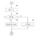
在单元保持步骤S30中,控制单元20从转向角传感器(未示出)接收转向角信号θ,并且从车辆的车辆速度传感器或曲柄位置传感器接收车辆的驱动速度v,所述转向角传感器感测是否在操纵车辆的方向盘并且感测方向盘的角度。存储在存储单元30中的预定数据包括对应于车辆驱动速度v的转向判定基准角θv的相关数据。控制单元20执行转向判定基准角计算步骤S31,以使用车辆的输入驱动速度v来计算车辆的转向判定基准角θv。也就是说,转向判定基准角θv被形成为驱动速度的函数,例如,形式为对数函数或含有这种类型图示的映射数据的函数,并且可以使用插值来得到。控制单元20使用存储在存储单元30中的转向判定基准角数据,通过算术逻辑单元40的操作来根据车辆的驱动速度计算转向判定基准角。因为如果车辆的驱动速度高则驾驶员的转向角范围小,所以用于判定是否在操纵方向盘的转向判定基准角θv的值小,而因为如果车辆的驱动速度低则用于转向的转向角的变化范围大于高速驱动时的变化范围,所以用于判定是否在操纵方向盘的转向判定基准角θv的值小于高速驱动时的值。In the unit holding step S30, the
然后,控制单元20执行转向状态判定步骤S33。控制单元20通过将从车辆的转向角传感器输入的转向角信号θ与从车辆的驱动速度v计算出的转向判定基准角θv进行比较,判定驾驶员是否进行转向。如果在步骤S33中判定了转向角信号θ大于转向判定基准角θv,则控制单元20判定驾驶员当前在操纵方向盘并且没有操纵触觉式方向盘开关设备的拇指轮或按钮,并且控制单元20执行单元信号保持步骤S35,以根据从触觉轮装置感测单元330、按钮开关单元500或按压开关单元400接收的电信号来阻止某一操作模式的执行。Then, the
另一方面,如果在步骤S33中判定了转向角信号θ小于转向判定基准角θv,则控制单元20判定驾驶员当前没有在操纵方向盘而是在操纵触觉式方向盘开关设备的拇指轮或按钮,并且控制单元20执行单元信号保持步骤S35,以根据从触觉轮装置感测单元330、按钮开关单元500或按压开关单元400接收的电信号来执行某一操作模式。On the other hand, if it is determined in step S33 that the steering angle signal θ is smaller than the steering determination reference angle θv , the
上述实施方式仅仅是示例性的以描述本发明,其并不旨在限制本发明,而是可以以多种方式解释。The above-mentioned embodiments are merely exemplary to describe the present invention, and are not intended to limit the present invention, but can be interpreted in various ways.
如上构造的根据本发明的触觉式方向盘开关设备具有下列有利效果。The tactile steering wheel switch device according to the present invention constructed as above has the following advantageous effects.
首先,根据本发明的触觉式方向盘开关设备包括双轴旋转式触觉轮装置致动器,从而能实现更紧凑和准确的旋转感测结构。First, the tactile steering wheel switch apparatus according to the present invention includes a biaxial rotary tactile wheel device actuator, thereby enabling a more compact and accurate rotation sensing structure.
其次,根据本发明的触觉式方向盘开关设备能通过触觉旋钮同时地实施旋转操作和按压操作,从而能实现紧凑的构造和更准确的操作。此外,能够实施通过按压开关单元进行定向操作以便提供将被操作的开关一体化的简化结构,从而有利于触觉式方向盘开关设备的制造并显著降低制造成本。Second, the tactile steering wheel switch device according to the present invention can simultaneously perform a rotating operation and a pressing operation through a tactile knob, thereby enabling a compact configuration and more accurate operation. Furthermore, directional operation by pressing the switch unit can be implemented to provide a simplified structure in which the switches to be operated are integrated, thereby facilitating the manufacture of the tactile steering wheel switch device and significantly reducing the manufacturing cost.
第三,根据本发明的触觉式方向盘开关设备能通过设置在触觉旋钮外部的按钮开关单元执行更简化和组合的开关功能。Third, the tactile steering wheel switch device according to the present invention can perform more simplified and combined switch functions through the push button switch unit provided outside the tactile knob.
第四,根据本发明的触觉式方向盘开关设备能够响应于通过设置在触觉旋钮或按钮开关单元中的光源单元的开关操作输出预定光而允许驾驶员进行更快速的视觉感知。Fourth, the tactile steering wheel switch device according to the present invention is capable of outputting predetermined light in response to a switching operation of a light source unit provided in a tactile knob or push button switch unit to allow a driver to perform faster visual perception.
第五,根据本发明的触觉式方向盘开关设备能通过滤色器实施简化而组合的图标输出功能,从而以低制造成本实现组合的功能。Fifth, the tactile steering wheel switch device according to the present invention can implement simplified and combined icon output functions through color filters, thereby realizing combined functions at low manufacturing cost.
第六,根据本发明的触觉式方向盘开关设备允许牢固地安装触觉轮装置致动器,使得在操纵开关旋钮时惯性矩影响最小化,从而有利于操纵触觉旋钮。Sixth, the tactile steering wheel switch apparatus according to the present invention allows the tactile wheel device actuator to be securely installed so that the influence of the moment of inertia is minimized when the switch knob is manipulated, thereby facilitating the manipulation of the tactile knob.
第七,根据本发明的触觉式方向盘开关设备能通过设置在按钮开关单元中的按钮滤光器单元识别可变符号,从而可以改进操纵性能。Seventh, the tactile steering wheel switch device according to the present invention can recognize variable symbols through the button filter unit provided in the button switch unit, so that manipulability can be improved.
第八,根据本发明的触觉式方向盘开关设备可使用转向角的相关信息来防止由开关的误操纵造成的故障,从而可以确保操作的稳定性。Eighth, the tactile steering wheel switch device according to the present invention can prevent malfunctions caused by mismanipulation of switches using information on steering angle, so that stability of operation can be ensured.
虽然已结合附图中所示的示例性实施方式描述了本发明,但其仅仅是示例性的,并且本发明不限于这些实施方式。应当理解,在不脱离本发明的精神和范围的情况下,本领域的普通技术人员可进行实施方式的各种等同改变和变型。因此,本发明的真实技术范围应由所附权利要求的技术精神限定。Although the present invention has been described in connection with the exemplary embodiments shown in the drawings, these are only exemplary and the present invention is not limited to these embodiments. It should be understood that various equivalent changes and modifications of the embodiments can be made by those skilled in the art without departing from the spirit and scope of the present invention. Therefore, the true technical scope of the present invention should be defined by the technical spirit of the appended claims.
Claims (10)
Applications Claiming Priority (6)
| Application Number | Priority Date | Filing Date | Title |
|---|---|---|---|
| KR10-2011-0038251 | 2011-04-25 | ||
| KR1020110038251AKR101857283B1 (en) | 2011-04-25 | 2011-04-25 | Steering wheel switching haptical unit and apparatus with the same unit |
| KR10-2011-0038250 | 2011-04-25 | ||
| KR1020110038250AKR101268626B1 (en) | 2011-04-25 | 2011-04-25 | Steering wheel switching haptical unit and apparatus with the same unit |
| KR1020120033411AKR101318065B1 (en) | 2012-03-30 | 2012-03-30 | Steering wheel switching haptical unit |
| KR10-2012-0033411 | 2012-03-30 |
Publications (2)
| Publication Number | Publication Date |
|---|---|
| CN102756752Atrue CN102756752A (en) | 2012-10-31 |
| CN102756752B CN102756752B (en) | 2016-03-09 |
Family
ID=46026711
Family Applications (1)
| Application Number | Title | Priority Date | Filing Date |
|---|---|---|---|
| CN201210125416.7AActiveCN102756752B (en) | 2011-04-25 | 2012-04-25 | Haptic steering wheel switch apparatus |
Country Status (4)
| Country | Link |
|---|---|
| US (1) | US8987620B2 (en) |
| EP (1) | EP2518592B1 (en) |
| JP (1) | JP5393833B2 (en) |
| CN (1) | CN102756752B (en) |
Cited By (11)
| Publication number | Priority date | Publication date | Assignee | Title |
|---|---|---|---|---|
| CN104936813A (en)* | 2013-01-14 | 2015-09-23 | Trw车辆电气与零件有限公司 | Operating device, vehicle steering wheel and method for operating an operating device |
| CN105263737A (en)* | 2013-04-05 | 2016-01-20 | 法雷奥开关和传感器有限责任公司 | Control device for a motor vehicle and steering wheel comprising a control device |
| CN106024437A (en)* | 2015-03-24 | 2016-10-12 | 东洋电装株式会社 | Multifunctional selection operation switch apparatus |
| CN106200424A (en)* | 2015-05-27 | 2016-12-07 | Zodiac航空电器 | For the Hall effect general controls push button of man-machine interface and be equipped with the man-machine interface of this control push button |
| CN108369875A (en)* | 2015-12-30 | 2018-08-03 | 三星电子株式会社 | Switch module and cooker including it |
| CN109343385A (en)* | 2018-09-28 | 2019-02-15 | 武汉德普新源科技有限公司 | A kind of rotary multipoint switch switching device, control system and control method |
| CN110053031A (en)* | 2019-04-25 | 2019-07-26 | 深圳市启玄科技有限公司 | A kind of robot control assembly and method based on tactile |
| CN110853949A (en)* | 2019-11-01 | 2020-02-28 | 珠海优特电力科技股份有限公司 | Disconnecting link on-off state detection device |
| CN105333459B (en)* | 2014-07-30 | 2020-06-16 | 博西华电器(江苏)有限公司 | Operating device for cooker and cooker |
| CN112889124A (en)* | 2018-03-07 | 2021-06-01 | 莫贝斯电子株式会社 | Automobile switch device |
| CN114461073A (en)* | 2015-07-01 | 2022-05-10 | 因文图斯工程有限公司 | Method for operating a technical device or apparatus and method for assisting the rehabilitation of a person after a disease |
Families Citing this family (44)
| Publication number | Priority date | Publication date | Assignee | Title |
|---|---|---|---|---|
| EP2518591B1 (en) | 2011-04-25 | 2018-05-30 | LS Automotive Technologies Co., Ltd. | Haptic steering wheel switch apparatus and haptic steering wheel switch system including the same |
| EP2518592B1 (en) | 2011-04-25 | 2017-07-26 | Daesung Electric Co., Ltd | Haptic steering wheel switch apparatus |
| KR101879874B1 (en)* | 2012-01-30 | 2018-07-18 | 두산인프라코어 주식회사 | Engine control apparatus in construction machinery |
| CN104736412B (en) | 2012-10-23 | 2018-06-29 | Tk控股公司 | Steering wheel lamp bar |
| WO2014066477A1 (en) | 2012-10-23 | 2014-05-01 | Tk Holdings Inc. | Steering wheel light bar |
| DE112013005126T5 (en) | 2012-10-23 | 2015-07-16 | Tk Holdings Inc. | Steering Wheel lightbar |
| US20140163768A1 (en)* | 2012-12-11 | 2014-06-12 | At&T Intellectual Property I, L.P. | Event and condition determination based on sensor data |
| DE102013001876A1 (en)* | 2013-02-02 | 2014-08-07 | Daimler Ag | Operating device with optical finger navigation module for a steering wheel |
| JP6851197B2 (en) | 2013-05-30 | 2021-03-31 | ティーケー ホールディングス インク.Tk Holdings Inc. | Multidimensional trackpad |
| WO2015054362A1 (en) | 2013-10-08 | 2015-04-16 | Tk Holdings Inc. | Force-based touch interface with ingrated multi-sensory feedback |
| US9874945B2 (en)* | 2014-02-13 | 2018-01-23 | Microsoft Technology Licensing, Llc | Low-profile pointing stick |
| JP6336319B2 (en)* | 2014-04-14 | 2018-06-06 | 矢崎総業株式会社 | Display device |
| JP6648109B2 (en) | 2014-07-23 | 2020-02-14 | ジョイソン セイフティ システムズ アクイジション エルエルシー | Steering grip light bar system |
| FR3026499B1 (en)* | 2014-09-30 | 2017-04-14 | Delphi Tech Inc | HAND-WHEEL CONTROL SYSTEM |
| US10466826B2 (en) | 2014-10-08 | 2019-11-05 | Joyson Safety Systems Acquisition Llc | Systems and methods for illuminating a track pad system |
| US10532659B2 (en) | 2014-12-30 | 2020-01-14 | Joyson Safety Systems Acquisition Llc | Occupant monitoring systems and methods |
| US9533687B2 (en) | 2014-12-30 | 2017-01-03 | Tk Holdings Inc. | Occupant monitoring systems and methods |
| US10614328B2 (en) | 2014-12-30 | 2020-04-07 | Joyson Safety Acquisition LLC | Occupant monitoring systems and methods |
| JP2016127518A (en)* | 2015-01-07 | 2016-07-11 | 株式会社デンソー | Remote controller |
| US9580012B2 (en) | 2015-03-02 | 2017-02-28 | Tk Holdings Inc. | Vehicle object detection and notification system |
| USD806729S1 (en) | 2015-04-24 | 2018-01-02 | Tk Holdings, Inc. | Display screen with graphical user interface |
| WO2016172709A1 (en) | 2015-04-24 | 2016-10-27 | Tk Holdings Inc. | Steering wheel light bar |
| USD807308S1 (en)* | 2016-08-10 | 2018-01-09 | Caterpillar Inc. | Jog dial for a switch panel user interface |
| USD807309S1 (en)* | 2016-08-10 | 2018-01-09 | Caterpillar Inc. | Rotary dial for a switch panel user interface |
| USD847190S1 (en) | 2017-01-04 | 2019-04-30 | Joyson Safety Systems Acquisition Llc | Steering wheel display screen with graphical user interface |
| WO2018129149A1 (en) | 2017-01-04 | 2018-07-12 | Joyson Safety Systems Acquisition Llc | Switch assembly and methods of use |
| JP7142638B2 (en) | 2017-01-04 | 2022-09-27 | ジョイソン セイフティ システムズ アクイジション エルエルシー | Vehicle lighting system and method |
| US10613675B2 (en)* | 2017-04-24 | 2020-04-07 | Dell Products L.P. | Information handling system totem pressure sensor |
| US10613649B2 (en) | 2017-04-24 | 2020-04-07 | Dell Products L.P. | Information handling system totem holder |
| USD848381S1 (en)* | 2017-07-20 | 2019-05-14 | Weibing Cheng | Automobile multimedia wireless controller |
| JP7036371B2 (en)* | 2018-01-19 | 2022-03-15 | 朝日電装株式会社 | Vehicle operation device |
| JP7036373B2 (en)* | 2018-01-19 | 2022-03-15 | 朝日電装株式会社 | Vehicle operation device |
| EP3537266A1 (en)* | 2018-03-05 | 2019-09-11 | Advanced Silicon SA | Transparent button for capacitive touch screen |
| WO2019173750A1 (en) | 2018-03-08 | 2019-09-12 | Joyson Safety Systems Acquisition Llc | Vehicle illumination systems and methods |
| JP7433845B2 (en)* | 2018-12-06 | 2024-02-20 | 株式会社クボタ | work vehicle |
| US10647344B1 (en) | 2019-01-31 | 2020-05-12 | Toyota Motor Engineering & Manufacturing North America, Inc. | Multi-function vehicle input devices with convex dials for vehicle systems control and methods incorporating the same |
| US11231814B1 (en)* | 2019-10-31 | 2022-01-25 | Apple Inc. | Electronic devices with curved display surfaces |
| US11422629B2 (en) | 2019-12-30 | 2022-08-23 | Joyson Safety Systems Acquisition Llc | Systems and methods for intelligent waveform interruption |
| JP7489209B2 (en)* | 2020-03-30 | 2024-05-23 | 東京測定器材株式会社 | Operating device |
| DE102020206862A1 (en)* | 2020-06-02 | 2021-12-02 | Deere & Company | Procedure for adjusting the position of a power lift |
| JP7687811B2 (en)* | 2020-07-30 | 2025-06-03 | ヤンマーホールディングス株式会社 | Operation device, work vehicle, and operation control method |
| CN112216546B (en)* | 2020-10-30 | 2024-03-22 | 上海延锋金桥汽车饰件系统有限公司 | Electronic switch |
| GB2607922A (en)* | 2021-06-16 | 2022-12-21 | Daimler Ag | Haptic control module for a vehicle |
| JP2024051363A (en)* | 2022-09-30 | 2024-04-11 | 富士フイルム株式会社 | Dials and Operating Mechanisms |
Citations (5)
| Publication number | Priority date | Publication date | Assignee | Title |
|---|---|---|---|---|
| US6703999B1 (en)* | 2000-11-13 | 2004-03-09 | Toyota Jidosha Kabushiki Kaisha | System for computer user interface |
| EP1575017A1 (en)* | 2004-03-10 | 2005-09-14 | Calsonic Kansei Corporation | Display device |
| US20060155441A1 (en)* | 2004-03-04 | 2006-07-13 | Delphi Technologies, Inc. | Vehicle information system with steering wheel controller |
| CN101878134A (en)* | 2008-05-26 | 2010-11-03 | 大星电机工业株式会社 | Haptic steering wheel switch device and haptic steering wheel switch system including the same |
| WO2010150933A1 (en)* | 2009-06-23 | 2010-12-29 | 대성전기공업 주식회사 | Combined switch unit and combined switch module having same |
Family Cites Families (37)
| Publication number | Priority date | Publication date | Assignee | Title |
|---|---|---|---|---|
| JPS613637U (en)* | 1984-06-14 | 1986-01-10 | 矢崎総業株式会社 | Electric mirror switch |
| JPH0219656A (en) | 1988-07-06 | 1990-01-23 | Nippon Carbureter Co Ltd | Idling speed controller for engine |
| JPH0219656U (en)* | 1988-07-26 | 1990-02-08 | ||
| US5855144A (en) | 1992-07-13 | 1999-01-05 | Parada; Nikolay | Steering wheel |
| JPH09161612A (en) | 1995-12-08 | 1997-06-20 | Tokai Rika Co Ltd | Master switch for power window |
| KR970040790A (en) | 1995-12-15 | 1997-07-24 | 전성원 | Handle with centralized control panel |
| US6636197B1 (en)* | 1996-11-26 | 2003-10-21 | Immersion Corporation | Haptic feedback effects for control, knobs and other interface devices |
| JPH10334771A (en)* | 1997-05-30 | 1998-12-18 | Tokyo Seat Kk | Steering wheel operation device |
| JPH10340152A (en) | 1997-06-05 | 1998-12-22 | Matsushita Electric Ind Co Ltd | On-vehicle audio system and its operating method |
| JP2001171525A (en) | 1999-12-15 | 2001-06-26 | Tokai Rika Co Ltd | Switch structure for steering wheel |
| JP2001345031A (en) | 2000-05-31 | 2001-12-14 | Alps Electric Co Ltd | Composite operating type electronic parts |
| JP2003022137A (en) | 2001-07-05 | 2003-01-24 | Alps Electric Co Ltd | Inner force sense generation and input device |
| US8364342B2 (en)* | 2001-07-31 | 2013-01-29 | Immersion Corporation | Control wheel with haptic feedback |
| JP3920599B2 (en) | 2001-08-07 | 2007-05-30 | アルプス電気株式会社 | Manual input device |
| JP2003063326A (en) | 2001-08-28 | 2003-03-05 | Nissan Motor Co Ltd | Steering switch |
| TW588812U (en) | 2001-12-14 | 2004-05-21 | Lite On Technology Corp | Knob structure |
| JP2003327059A (en) | 2002-03-08 | 2003-11-19 | Calsonic Kansei Corp | Input device for vehicle |
| JP2004146090A (en) | 2002-10-22 | 2004-05-20 | Pioneer Electronic Corp | Multifunction operation unit |
| JP3970756B2 (en)* | 2002-12-03 | 2007-09-05 | アルプス電気株式会社 | Illuminated switch device |
| JP2004228022A (en)* | 2003-01-27 | 2004-08-12 | Alps Electric Co Ltd | Rotational operation type input device |
| KR20040106162A (en) | 2003-06-11 | 2004-12-17 | 현대모비스 주식회사 | Apparatus for selecting the function in a car |
| US20050018172A1 (en) | 2003-07-23 | 2005-01-27 | Neil Gelfond | Accepting user control |
| DE102004007253B3 (en) | 2004-02-10 | 2005-06-09 | Takata-Petri Ag | Automobile steering wheel incorporating operating device for control and/or regulation of automobile component parts, e.g. safety systems, provided by reflection optical sensor device |
| ITBO20040484A1 (en) | 2004-07-30 | 2004-10-30 | Ferrari Spa | STEERING WHEEL FOR A VEHICLE |
| US7987030B2 (en) | 2005-05-25 | 2011-07-26 | GM Global Technology Operations LLC | Vehicle illumination system and method |
| US7439459B2 (en) | 2005-09-05 | 2008-10-21 | Alps Electric Co., Ltd. | Switch device and steering switch apparatus equipped with the switch device |
| DE102005061285A1 (en) | 2005-12-20 | 2007-06-21 | Lemförder Electronic GmbH | Selection device for shifting vehicle gearbox, has control unit rotatable about rotational axis, and actuator delivering turning moment to shaft, where shaft extends between rotation angle detecting device and control unit along axis |
| KR100877067B1 (en) | 2006-01-03 | 2009-01-07 | 삼성전자주식회사 | Haptic Buttons and Haptic Devices Using the Same |
| JP2007234482A (en) | 2006-03-02 | 2007-09-13 | Denso Corp | Dialing operation device |
| JP4779813B2 (en)* | 2006-06-08 | 2011-09-28 | トヨタ自動車株式会社 | Vehicle control device |
| JP2008047370A (en) | 2006-08-11 | 2008-02-28 | Mic Electron Co | Push-type switch and composite switch including the same |
| JP4804368B2 (en)* | 2007-01-12 | 2011-11-02 | カルソニックカンセイ株式会社 | Variable display structure |
| JP4785776B2 (en) | 2007-03-19 | 2011-10-05 | カルソニックカンセイ株式会社 | Variable display structure |
| KR100947729B1 (en) | 2008-06-10 | 2010-03-16 | 대성전기공업 주식회사 | Steering wheel haptic switch unit and steering wheel haptic switch system having same |
| JP2010010023A (en)* | 2008-06-30 | 2010-01-14 | Shin Etsu Polymer Co Ltd | Member for display, and member for push-button switch using the same |
| JP2010244899A (en) | 2009-04-07 | 2010-10-28 | Alps Electric Co Ltd | Input device |
| EP2518592B1 (en) | 2011-04-25 | 2017-07-26 | Daesung Electric Co., Ltd | Haptic steering wheel switch apparatus |
- 2012
- 2012-04-24EPEP12165379.4Apatent/EP2518592B1/ennot_activeNot-in-force
- 2012-04-25JPJP2012099811Apatent/JP5393833B2/enactiveActive
- 2012-04-25CNCN201210125416.7Apatent/CN102756752B/enactiveActive
- 2012-04-25USUS13/455,496patent/US8987620B2/enactiveActive
Patent Citations (5)
| Publication number | Priority date | Publication date | Assignee | Title |
|---|---|---|---|---|
| US6703999B1 (en)* | 2000-11-13 | 2004-03-09 | Toyota Jidosha Kabushiki Kaisha | System for computer user interface |
| US20060155441A1 (en)* | 2004-03-04 | 2006-07-13 | Delphi Technologies, Inc. | Vehicle information system with steering wheel controller |
| EP1575017A1 (en)* | 2004-03-10 | 2005-09-14 | Calsonic Kansei Corporation | Display device |
| CN101878134A (en)* | 2008-05-26 | 2010-11-03 | 大星电机工业株式会社 | Haptic steering wheel switch device and haptic steering wheel switch system including the same |
| WO2010150933A1 (en)* | 2009-06-23 | 2010-12-29 | 대성전기공업 주식회사 | Combined switch unit and combined switch module having same |
Cited By (16)
| Publication number | Priority date | Publication date | Assignee | Title |
|---|---|---|---|---|
| CN104936813B (en)* | 2013-01-14 | 2018-08-03 | Trw车辆电气与零件有限公司 | Operating device, steering wheel for vehicle and the method for running operating device |
| CN104936813A (en)* | 2013-01-14 | 2015-09-23 | Trw车辆电气与零件有限公司 | Operating device, vehicle steering wheel and method for operating an operating device |
| CN105263737A (en)* | 2013-04-05 | 2016-01-20 | 法雷奥开关和传感器有限责任公司 | Control device for a motor vehicle and steering wheel comprising a control device |
| CN105263737B (en)* | 2013-04-05 | 2018-04-17 | 法雷奥开关和传感器有限责任公司 | Control device for motor vehicles and steering wheel with control device |
| CN105333459B (en)* | 2014-07-30 | 2020-06-16 | 博西华电器(江苏)有限公司 | Operating device for cooker and cooker |
| CN106024437A (en)* | 2015-03-24 | 2016-10-12 | 东洋电装株式会社 | Multifunctional selection operation switch apparatus |
| CN106200424A (en)* | 2015-05-27 | 2016-12-07 | Zodiac航空电器 | For the Hall effect general controls push button of man-machine interface and be equipped with the man-machine interface of this control push button |
| CN114461073A (en)* | 2015-07-01 | 2022-05-10 | 因文图斯工程有限公司 | Method for operating a technical device or apparatus and method for assisting the rehabilitation of a person after a disease |
| CN108369875A (en)* | 2015-12-30 | 2018-08-03 | 三星电子株式会社 | Switch module and cooker including it |
| CN112889124A (en)* | 2018-03-07 | 2021-06-01 | 莫贝斯电子株式会社 | Automobile switch device |
| CN109343385B (en)* | 2018-09-28 | 2021-01-26 | 武汉德普新源科技有限公司 | Rotary type multi-point switch switching device, control system and control method |
| CN109343385A (en)* | 2018-09-28 | 2019-02-15 | 武汉德普新源科技有限公司 | A kind of rotary multipoint switch switching device, control system and control method |
| CN110053031B (en)* | 2019-04-25 | 2020-10-09 | 深圳市启玄科技有限公司 | Robot control assembly and method based on touch sense |
| CN110053031A (en)* | 2019-04-25 | 2019-07-26 | 深圳市启玄科技有限公司 | A kind of robot control assembly and method based on tactile |
| CN110853949A (en)* | 2019-11-01 | 2020-02-28 | 珠海优特电力科技股份有限公司 | Disconnecting link on-off state detection device |
| CN110853949B (en)* | 2019-11-01 | 2021-10-29 | 珠海优特电力科技股份有限公司 | Disconnecting link on-off state detection device |
Also Published As
| Publication number | Publication date |
|---|---|
| EP2518592A2 (en) | 2012-10-31 |
| EP2518592B1 (en) | 2017-07-26 |
| US8987620B2 (en) | 2015-03-24 |
| EP2518592A3 (en) | 2014-03-05 |
| CN102756752B (en) | 2016-03-09 |
| JP2012230901A (en) | 2012-11-22 |
| US20120267222A1 (en) | 2012-10-25 |
| JP5393833B2 (en) | 2014-01-22 |
Similar Documents
| Publication | Publication Date | Title |
|---|---|---|
| CN102756752B (en) | Haptic steering wheel switch apparatus | |
| EP2518591B1 (en) | Haptic steering wheel switch apparatus and haptic steering wheel switch system including the same | |
| US8358279B2 (en) | Sensation system | |
| JP6005883B2 (en) | Shift range switch device for vehicle | |
| JP6454882B2 (en) | Input operation device | |
| KR101857283B1 (en) | Steering wheel switching haptical unit and apparatus with the same unit | |
| KR101773032B1 (en) | Multifunctional composite input device | |
| KR101091273B1 (en) | Multiple switch unit, multiple switch device having same and control method thereof | |
| CN107867243A (en) | Mobile unit operates accessory system | |
| KR20120071027A (en) | Haptic switch mounted on steering wheel | |
| EP3059751B1 (en) | Operating panel device | |
| KR101268626B1 (en) | Steering wheel switching haptical unit and apparatus with the same unit | |
| KR100922695B1 (en) | Sensation system | |
| KR101165174B1 (en) | Integrated switching unit with directional switch and apparatus with the unit and method for controlling the apparatus | |
| JP2004228022A (en) | Rotational operation type input device | |
| KR102370914B1 (en) | Input apparatus and vehicle including the same | |
| KR100960219B1 (en) | Haptic Switch Unit and Haptic Switch System Having Same | |
| JP4209300B2 (en) | Joystick type input device | |
| KR101003193B1 (en) | Steering wheel haptic switch unit and steering wheel haptic switch system having same | |
| US20070057974A1 (en) | Scroll button assembly for video game controller | |
| EP4169759B1 (en) | Vehicle function operation apparatus and method | |
| KR101421739B1 (en) | Steering wheel switch unit | |
| KR101417059B1 (en) | Sensation system with haptic switching unit | |
| KR20200062840A (en) | Knob assembly of vehicle multimedia device |
Legal Events
| Date | Code | Title | Description |
|---|---|---|---|
| C06 | Publication | ||
| PB01 | Publication | ||
| C10 | Entry into substantive examination | ||
| SE01 | Entry into force of request for substantive examination | ||
| C14 | Grant of patent or utility model | ||
| GR01 | Patent grant | ||
| C56 | Change in the name or address of the patentee | ||
| CP01 | Change in the name or title of a patent holder | Address after:Gyeonggi Do, South Korea Patentee after:LS automotive electronics Address before:Gyeonggi Do, South Korea Patentee before:Daesung Electric Co., Ltd. | |
| TR01 | Transfer of patent right | ||
| TR01 | Transfer of patent right | Effective date of registration:20180329 Address after:Gyeonggi Do, South Korea Patentee after:Le Star Automotive Technology Co., Ltd. Address before:Gyeonggi Do, South Korea Patentee before:LS automotive electronics |