CN102738869A - Wireless charging mobile power supply and charging and discharging method - Google Patents
Wireless charging mobile power supply and charging and discharging methodDownload PDFInfo
- Publication number
- CN102738869A CN102738869ACN2012102286127ACN201210228612ACN102738869ACN 102738869 ACN102738869 ACN 102738869ACN 2012102286127 ACN2012102286127 ACN 2012102286127ACN 201210228612 ACN201210228612 ACN 201210228612ACN 102738869 ACN102738869 ACN 102738869A
- Authority
- CN
- China
- Prior art keywords
- charging
- wireless
- unit
- module
- input interface
- Prior art date
- Legal status (The legal status is an assumption and is not a legal conclusion. Google has not performed a legal analysis and makes no representation as to the accuracy of the status listed.)
- Granted
Links
- 238000000034methodMethods0.000titleclaimsabstractdescription31
- 238000007599dischargingMethods0.000titleclaimsabstractdescription21
- 230000006698inductionEffects0.000claimsabstractdescription47
- 230000005540biological transmissionEffects0.000claimsdescription25
- 238000005070samplingMethods0.000claimsdescription15
- 230000005674electromagnetic inductionEffects0.000claimsdescription8
- 238000010586diagramMethods0.000description7
- 230000000694effectsEffects0.000description3
- 238000012795verificationMethods0.000description2
- 230000005611electricityEffects0.000description1
- 238000010438heat treatmentMethods0.000description1
- 230000001939inductive effectEffects0.000description1
Images


Classifications
- Y—GENERAL TAGGING OF NEW TECHNOLOGICAL DEVELOPMENTS; GENERAL TAGGING OF CROSS-SECTIONAL TECHNOLOGIES SPANNING OVER SEVERAL SECTIONS OF THE IPC; TECHNICAL SUBJECTS COVERED BY FORMER USPC CROSS-REFERENCE ART COLLECTIONS [XRACs] AND DIGESTS
- Y02—TECHNOLOGIES OR APPLICATIONS FOR MITIGATION OR ADAPTATION AGAINST CLIMATE CHANGE
- Y02E—REDUCTION OF GREENHOUSE GAS [GHG] EMISSIONS, RELATED TO ENERGY GENERATION, TRANSMISSION OR DISTRIBUTION
- Y02E60/00—Enabling technologies; Technologies with a potential or indirect contribution to GHG emissions mitigation
- Y02E60/10—Energy storage using batteries
Landscapes
- Charge And Discharge Circuits For Batteries Or The Like (AREA)
Abstract
Description
Translated fromChinese技术领域technical field
本发明涉及一种无线充电电源,尤其涉及一种可通过无线方式充放电的移动电源及充放电方法。The invention relates to a wireless charging power supply, in particular to a mobile power supply capable of charging and discharging in a wireless manner and a charging and discharging method.
背景技术Background technique
随着人们生活水平的提高,电子产品(例如手机、手电筒、小风扇、电动刮胡刀、桌灯、头灯、露营灯等产品)已经成为现代人必不可少的常用品,这些产品有时由于使用的频繁和使用场所的局限性,需要经常充电,为了便于外出充电,现有技术人员研发出了一种移动式充电电源,这种移动式充电电源内包含有蓄电电池,在使用时可通过以下几种方式充电:一种是直接通过数据线将电子产品和移动式充电电源的充电插头连接起来,能量从充电插头导入电子产品的电池中储存起来;第二种将移动式充电电源设置成充电座的方式,通过充电座将能量导入电子产品的充电电池内储存起来。由于第一种需要使用数据线才能完成充电,每次充电都需要将数据线的一端插到电子产品上,等到充完电后再拔下来,这样不仅麻烦,而且常常出现短线、插座松脱等问题,不但充电效果不稳定,而且会对电子产品造成损害;第二种必须将电子产品放入充电座内,必须确保电子产品的充电端与充电座的放电端连接在一起,在晃动或者长时间使用后往往会由于错位造成电子产品的充电端和充电座的放电端接触不良,以使电子产品与充电座连接不稳定。另一方面,上述移动式充电电源对于应急灯、露营灯等产品而言,由于这类电子用品在不使用时往往处于充电状态,使用时,使用者有时难以及时将产品从充电座或者充电电源上取下,为此,现有技术人员开发出来了一种非接触式充电电源。With the improvement of people's living standards, electronic products (such as mobile phones, flashlights, small fans, electric shavers, table lamps, headlamps, camping lamps, etc.) The frequency of use and the limitations of the place of use require frequent charging. In order to facilitate charging when going out, existing technical personnel have developed a mobile charging power supply. This mobile charging power supply contains a storage battery, which can Charge in the following ways: one is to directly connect the electronic product with the charging plug of the mobile charging power supply through the data cable, and the energy is stored in the battery of the electronic product from the charging plug; the second is to set the mobile charging power supply In the way of forming a charging stand, the energy is introduced into the rechargeable battery of the electronic product through the charging stand and stored. Since the first type requires the use of a data cable to complete charging, one end of the data cable needs to be plugged into the electronic product every time it is charged, and then unplugged after charging is complete. This is not only troublesome, but also often leads to short wires and loose sockets The problem is that not only the charging effect is unstable, but also it will cause damage to the electronic product; the second type must put the electronic product in the charging stand, and must ensure that the charging end of the electronic product is connected to the discharging end of the charging stand. After a long time of use, the charging end of the electronic product and the discharge end of the charging stand will often be in poor contact due to misalignment, so that the connection between the electronic product and the charging stand is unstable. On the other hand, for the above-mentioned mobile charging power supply for products such as emergency lights and camping lights, since such electronic appliances are often in a charging state when not in use, it is sometimes difficult for users to remove the product from the charging stand or charging power supply in time when in use. For this reason, prior art personnel have developed a kind of non-contact charging power source.
这一类非接触式充电电源可通过线圈单元的电磁感应对负载通过无线感应的方式充电,但是这类非接触式充电电源内电池充电时,必须通过数据线进行充电,充电效果不稳定,而且会对电子产品造成损害,因此,急需一种可解决上述问题的非接触式充电电源。This type of non-contact charging power supply can charge the load by wireless induction through the electromagnetic induction of the coil unit, but when charging the battery in this type of non-contact charging power supply, it must be charged through the data line, the charging effect is unstable, and Can cause damage to electronic products, therefore, a kind of non-contact charging power source that can solve the above-mentioned problems is urgently needed.
发明内容Contents of the invention
本发明的目的是提供一种非接触式充电电源,可通过无线感应的方式进行充电和放电。The purpose of the present invention is to provide a non-contact charging power supply, which can be charged and discharged through wireless induction.
本发明的另一目的是提供一种非接触式充电电源的充放电方法,可通过无线感应的方式进行充电和放电。Another object of the present invention is to provide a method for charging and discharging a non-contact charging power supply, which can be charged and discharged through wireless induction.
为了实现上有目的,本发明公开了一种无线充电式移动电源,包括线圈单元、蓄电模块、充电模块和升压模块,线圈单元用于发射并接受能量;蓄电模块由至少一个电池组成;充电模块的一端与所述线圈单元相连,另一端与所述蓄电模块相连,所述充电模块接受并处理所述线圈单元接受的能量,并将处理后的能量输送至所述蓄电模块;升压模块的一端与所述蓄电模块相连,另一端与所述线圈单元相连,所述充电模块将所述蓄电模块内的能量转换为输出电压并输出至线圈单元,所述线圈单元发射能量。In order to realize the purpose, the present invention discloses a wireless charging mobile power supply, which includes a coil unit, a power storage module, a charging module and a booster module, the coil unit is used to transmit and receive energy; the power storage module is composed of at least one battery ; One end of the charging module is connected to the coil unit, and the other end is connected to the power storage module, the charging module receives and processes the energy received by the coil unit, and sends the processed energy to the power storage module ; One end of the boost module is connected to the power storage module, and the other end is connected to the coil unit. The charging module converts the energy in the power storage module into an output voltage and outputs it to the coil unit. The coil unit emit energy.
与现有技术相比,本发明所述无线充电式移动电源通过所述线圈单元发射、接受能量,使得所述无线充电式移动电源可通过无线感应的方式进行充电和放电,而且使用同一线圈单元进行发射、接受能量,使得本发明结构简单,成本低。Compared with the prior art, the wireless rechargeable mobile power supply of the present invention transmits and receives energy through the coil unit, so that the wireless rechargeable mobile power supply can be charged and discharged by wireless induction, and the same coil unit is used Transmitting and receiving energy make the invention simple in structure and low in cost.
较佳地,所述充电模块包括控制单元、充电管理单元和AD采样单元,所述AD采样单元与所述蓄电模块相连并采集所述蓄电模块的实时电量值,所述控制单元一端与所述AD采样单元相连,另一端与所述充电管理单元相连,所述控制单元接受所述实时电量值,并依据所述实时电量值管理所述充电管理单元的充电方式,所述充电管理单元的另一端与所述蓄电模块相连,并依据相应的充电方式设置电池保护门限并限定充电电流。Preferably, the charging module includes a control unit, a charging management unit, and an AD sampling unit. The AD sampling unit is connected to the storage module and collects the real-time power value of the storage module. One end of the control unit is connected to the The AD sampling unit is connected, and the other end is connected to the charging management unit. The control unit receives the real-time power value and manages the charging mode of the charging management unit according to the real-time power value. The charging management unit The other end of the battery is connected to the storage module, and the battery protection threshold is set and the charging current is limited according to the corresponding charging method.
具体地,所述AD采样单元和控制单元之间还连接有电量指示单元,所述AD采样单元一端与所述电量指示单元相连并将所述实时电量值输送至电量指示单元,所述电量指示单元接受、处理所述实时电量值并将其转换为指示信号显示,且所述电量指示单元另一端与所述控制单元相连并将所述实时电量值输送至所述控制单元。Specifically, a power indicator unit is connected between the AD sampling unit and the control unit, and one end of the AD sampling unit is connected to the power indicator unit and transmits the real-time power value to the power indicator unit. The unit receives and processes the real-time power value and converts it into an indication signal for display, and the other end of the power indication unit is connected to the control unit and transmits the real-time power value to the control unit.
具体地,所述充电管理单元和所述蓄电模块之间还连接有电池保护单元。Specifically, a battery protection unit is also connected between the charge management unit and the power storage module.
具体地,在本发明的优选方案中,所述无线充电式移动电源还包括与所述充电模块相连的输入模块,所述输入模块包括并联的USB输入接口、电源输入接口和无线输入接口,所述无线输入接口包括所述线圈单元,所述USB输入接口和电源输入接口分别与所述充电管理单元和控制单元相连,所述控制单元控制所述充电管理单元切换所述USB输入接口、电源输入接口和无线输入接口。在该方案中,可通过无线感应、电源线和USB数据线对所述无线充电式移动电源进行充电,所述控制单元控制自动切换充电所用的输入接口。Specifically, in the preferred solution of the present invention, the wireless charging mobile power supply also includes an input module connected to the charging module, and the input module includes a parallel USB input interface, a power input interface and a wireless input interface, so The wireless input interface includes the coil unit, the USB input interface and the power input interface are respectively connected to the charging management unit and the control unit, and the control unit controls the charging management unit to switch between the USB input interface and the power input interface. interface and wireless input interface. In this solution, the wireless rechargeable mobile power supply can be charged through wireless induction, power lines and USB data lines, and the control unit controls automatic switching of input interfaces used for charging.
具体地,在本发明另一优选方案中,所述无线充电式移动电源还包括输入模块和切换开关,所述输入模块包括USB输入接口、电源输入接口和无线输入接口,所述无线输入接口包括所述线圈单元,所述切换开关一端分别与所述USB输入接口、电源输入接口和无线输入接口相连,另一端与所述充电管理单元相连,操作所述切换开关可控制所述充电管理单元切换所述USB输入接口、电源输入接口和无线输入接口。在该方案中,使用手动切换模式切换充电所用的输入接口。Specifically, in another preferred solution of the present invention, the wireless charging mobile power supply also includes an input module and a switch, the input module includes a USB input interface, a power input interface and a wireless input interface, and the wireless input interface includes For the coil unit, one end of the switching switch is respectively connected to the USB input interface, the power input interface and the wireless input interface, and the other end is connected to the charging management unit, and the switching of the charging management unit can be controlled by operating the switching switch. The USB input interface, the power input interface and the wireless input interface. In this scheme, a manual switching mode is used to switch the input interface used for charging.
较佳地,所述无线充电式移动电源还包括无线输出模块,所述无线输出模块包括无线发射控制单元、驱动单元和输出组件,所述无线发射控制单元识别接受终端信息,且所述无线发射控制单元的一端与所述升压模块相连并调节发射输出电压能量的发射频率,另一端与所述驱动单元相连并控制所述驱动单元动作,所述驱动单元另一端与所述输出组件相连并驱动所述输出组件,所述输出组件包括所述线圈单元并向外发射能量。该方案中,无线发射控制单元具有搭载身份配置和认证功能,主动识别接收终端(负载端)信息,具有异物识别功能,可根据不同的受电终端自动调节发射频率以保证最大效率的能量输出;所述无线充电式移动电源在充电或者未使用时,所述无线发射控制单元未检测到终端识别信息,此时所述无线发射控制单元控制所述驱动单元停止工作,所述无线输出模块处于休眠模式以节省电量;当无线发射控制单元检测到终端识别信息并通过身份验证的受电终端需要充电时,所述无线发射控制单元控制所述驱动单元工作,给予负载充电;当蓄电模块内的电池电量过低时,所述无线发射控制模块可控制切断电量输出以保护电池。Preferably, the wireless charging mobile power supply also includes a wireless output module, the wireless output module includes a wireless transmission control unit, a drive unit and an output component, the wireless transmission control unit identifies and accepts terminal information, and the wireless transmission One end of the control unit is connected to the boost module and adjusts the emission frequency of the emitted output voltage energy, the other end is connected to the drive unit and controls the action of the drive unit, and the other end of the drive unit is connected to the output assembly and The output component is driven, and the output component includes the coil unit and emits energy outward. In this solution, the wireless transmission control unit is equipped with identity configuration and authentication functions, actively identifies the information of the receiving terminal (load end), has the function of foreign object identification, and can automatically adjust the transmission frequency according to different power receiving terminals to ensure the maximum efficiency of energy output; When the wireless rechargeable mobile power supply is charging or not in use, the wireless transmission control unit does not detect terminal identification information. At this time, the wireless transmission control unit controls the drive unit to stop working, and the wireless output module is in sleep mode. mode to save power; when the wireless transmission control unit detects the terminal identification information and the power receiving terminal that has passed the identity verification needs to be charged, the wireless transmission control unit controls the drive unit to work and charge the load; when the power storage module When the battery power is too low, the wireless transmission control module can control to cut off the power output to protect the battery.
更具体地,所述无线充电式移动电源还包括与所述无线输出模块并联的USB输出接口。More specifically, the wireless rechargeable mobile power supply also includes a USB output interface connected in parallel with the wireless output module.
较佳地,所述线圈单元为电磁感应线圈单元、电波感应线圈单元或电磁共振线圈单元,在该方案中,所述无线充电时移动电源可通过电磁感应、电磁共振和电波感应三种方式发射接收能量,以实现无线充放电。Preferably, the coil unit is an electromagnetic induction coil unit, a radio wave induction coil unit or an electromagnetic resonance coil unit. In this scheme, the mobile power supply can emit electricity through electromagnetic induction, electromagnetic resonance and radio wave induction during wireless charging. Receive energy for wireless charging and discharging.
较佳地,所述线圈单元包括感应线圈、设于感应线圈外侧的导磁屏蔽层和设于感应线圈内的磁铁。其中,所述导磁屏蔽层可以提高线圈的品质,增加线圈的发射能力和接收能力,并可屏蔽线圈的外围,导线发射、接收方向,且导磁屏蔽层将感应线圈和蓄电模块内的电池隔离开来,防止电池发热;磁铁属于可选部件,可以进一步提高线圈的发射能力和接收能力。Preferably, the coil unit includes an induction coil, a magnetic shielding layer disposed outside the induction coil, and a magnet disposed inside the induction coil. Among them, the magnetically conductive shielding layer can improve the quality of the coil, increase the transmitting ability and receiving ability of the coil, and can shield the periphery of the coil, the direction of the wire transmitting and receiving, and the magnetically conductive shielding layer will connect the induction coil and the power storage module. The battery is isolated to prevent the battery from heating; the magnet is an optional part, which can further improve the transmitting and receiving capabilities of the coil.
较佳地,所述无线充电式移动电源外包覆有壳体,所述壳体内设有蓄电腔和感应腔,所述线圈单元安装于所述感应腔内,并在所述感应腔的外壁上形成冲电、放电的感应台,所述电池安装于所述蓄电腔内,并在所述蓄电腔的外侧设有可拆卸的电池门。Preferably, the wireless rechargeable mobile power supply is covered with a housing, and the housing is provided with a storage cavity and an induction cavity, and the coil unit is installed in the induction cavity, and in the induction cavity An induction table for charging and discharging is formed on the outer wall, the battery is installed in the storage chamber, and a detachable battery door is provided outside the storage chamber.
本发明还提供给了一种无线充电式移动电源的充放电方法,包括充电方法和放电方法,所述充电方法包括:(S11)使用一线圈单元采用无线感应的方式接收外部发射的能量并将其转换为输入电压,所述无线感应包括电磁感应、电波感应和电磁共振;(S12)将所述输入电压转换为供电池充电的充电电压并使所述电池充电。所述放电方法包括:(S21)将所述电池内的电能转换为额定输出电压;(S22)使用所述线圈单元采用无线感应的方式将所述额定输出电压转换为相应的能量发射出去。The present invention also provides a charging and discharging method for a wireless charging mobile power supply, including a charging method and a discharging method. The charging method includes: (S11) using a coil unit to receive externally transmitted energy by means of wireless induction and It is converted into an input voltage, and the wireless induction includes electromagnetic induction, radio wave induction and electromagnetic resonance; (S12) converting the input voltage into a charging voltage for charging a battery and charging the battery. The discharge method includes: (S21) converting the electric energy in the battery into a rated output voltage; (S22) using the coil unit to convert the rated output voltage into corresponding energy and emitting it by means of wireless induction.
与现有技术相比,一方面,本发明所述无线充电式移动电源的充放电方法通过所述线圈单元发射、接受能量从而进行充电和放电,另一方面,本发明使用同一线圈单元进行发射、接受能量,使得本发明结构简单,成本低。Compared with the prior art, on the one hand, the charging and discharging method of the wireless charging mobile power supply of the present invention transmits and receives energy through the coil unit to perform charging and discharging; on the other hand, the present invention uses the same coil unit to transmit 1. Accept energy, so that the structure of the present invention is simple and the cost is low.
附图说明Description of drawings
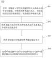
图1是本发明所述无线充电移动电源的结构框图。Fig. 1 is a structural block diagram of the wireless charging mobile power supply of the present invention.
图2是本发明优选实施例中所述无线充电移动电源的部分结构框图。Fig. 2 is a partial structural block diagram of the wireless charging mobile power supply in the preferred embodiment of the present invention.
图3是本发明另一优选实施例中所述无线充电移动电源的部分结构框图。Fig. 3 is a partial structural block diagram of the wireless charging mobile power supply in another preferred embodiment of the present invention.
图4是本发明又一优选实施例中所述无线充电移动电源的部分结构框图。Fig. 4 is a partial structural block diagram of the wireless charging mobile power supply in another preferred embodiment of the present invention.
图5是本发明所述无线充电移动电源中所述无线输出模块和USB输出接口的结构框图。Fig. 5 is a structural block diagram of the wireless output module and the USB output interface in the wireless charging mobile power supply of the present invention.
图6是本发明所述无线充电移动电源拆掉所述感应台后的结构示意图。Fig. 6 is a schematic structural diagram of the wireless charging mobile power supply of the present invention after removing the induction platform.
图7是本发明所述无线充电移动电源另一角度的结构示意图。Fig. 7 is a structural schematic diagram of another angle of the wireless charging mobile power supply of the present invention.
图8是本发明所述无线充电式移动电源的充放电方法的流程图。Fig. 8 is a flow chart of the charging and discharging method of the wireless charging mobile power supply according to the present invention.
具体实施方式Detailed ways
为详细说明本发明的技术内容、构造特征、所实现目的及效果,以下结合实施方式并配合附图详予说明。In order to describe the technical content, structural features, achieved goals and effects of the present invention in detail, the following will be described in detail in conjunction with the embodiments and accompanying drawings.
参考图1至图5,本发明公开了一种无线充电式移动电源100,不但可以通过无线感应的方式放电以对具有线圈单元的负载充电,而且可以使用无线感应的方式从能量发射端对其内的电池充电以储存电能。Referring to Figures 1 to 5, the present invention discloses a wireless charging
参考图1、图6和图7,本发明所述无线充电式移动电源100包括线圈单元10、蓄电模块30、充电模块20和升压模块40,线圈单元10用于发射并接受能量;蓄电模块30由至少一个电池31组成;充电模块20的一端与所述线圈单元10相连,另一端与所述蓄电模块30相连,所述充电模块20接受并处理所述线圈单元10接受的能量,并将处理后的能量输送至所述蓄电模块30;升压模块40的一端与所述蓄电模块30相连,另一端与所述线圈单元10相连,所述充电模块20将所述蓄电模块30内的能量转换为输出电压并输出至线圈单元10,所述线圈单元10发射能量。其中,所述线圈单元10为电磁感应线圈单元、电波感应线圈单元或电磁共振线圈单元,本实施例中所述蓄电模块30由两个电池31组成。Referring to Fig. 1, Fig. 6 and Fig. 7, the wireless charging
参考图1,描述本发明的工作原理:所述无线充电式移动电源100放电以对负载充电时,只需将具有感应接受线圈的负载放置在无线充电式移动电源100中内置有所述线圈单元10的充放电平台上,所述蓄电模块30开始放电,升压模块40将其转换为所需输出电压并通过线圈单元10发射能量至负载的感应接受线圈上,实现负载充电;当所述无线充电式移动电源100充电时,将具有无线发射线圈的充电座或者电源放置在无线充电式移动电源100中内置有所述线圈单元10的充放电平台上,能量从线圈单元10输入至充电模块20,所述充电模块20处理接受到的能量并将其转换为相应的充电电流输入至蓄电模块30内,实现无线充电式移动电源100的充电。Referring to Fig. 1, the working principle of the present invention is described: when the wireless rechargeable
较佳者,参考图2,所述充电模块20包括控制单元22、充电管理单元23和AD采样单元21,所述AD采样单元21与所述蓄电模块30相连并采集所述蓄电模块30的实时电量值,所述控制单元22一端与所述AD采样单元21相连,另一端与所述充电管理单元23相连,所述控制单元22接受所述实时电量值,并依据所述实时电量值管理所述充电管理单元23的充电方式,所述充电管理单元23的另一端与所述蓄电模块30相连,并依据相应的充电方式设置电池保护门限并限定充电电流。Preferably, referring to FIG. 2, the charging
更佳者,参考图4,所述AD采样单元21和控制单元22之间还连接有电量指示单元24,所述AD采样单元21一端与所述电量指示单元24相连并将所述实时电量值输送至电量指示单元24,所述电量指示单元24接受、处理所述实时电量值并将其转换为指示信号显示,且所述电量指示单元24另一端与所述控制单元22相连并将所述实时电量值输送至所述控制单元22。其中,所述电量指示单元24可使用指示灯指示实时电量,也可采用电子屏幕指示实时电量。More preferably, with reference to Fig. 4, an electric
更佳者,参考图4,所述充电管理单元23和所述蓄电模块30之间还连接有电池保护单元25,所述电池保护单元25保护电池组的充放电安全。More preferably, referring to FIG. 4 , a
较佳者,参考图2,在本发明第一优选实施例中,所述无线充电式移动电源100还包括与所述充电模块20相连的输入模块11,所述输入模块11包括并联的USB输入接口13、电源输入接口14和无线输入接口12,所述无线输入接口12包括所述线圈单元10,所述USB输入接口13和电源输入接口14分别与所述充电管理单元23和控制单元22相连,所述控制单元22控制所述充电管理单元23切换所述USB输入接口13、电源输入接口14和无线输入接口12。Preferably, referring to FIG. 2, in the first preferred embodiment of the present invention, the wireless charging
较佳者,参考图3,区别于本发明第一优选实施例,在本发明第二优选实施例中,所述无线充电式移动电源100还包括输入模块11和切换开关15,所述输入模块11包括USB输入接口13、电源输入接口14和无线输入接口12,所述无线输入接口12包括所述线圈单元10,所述切换开关15一端分别与所述USB输入接口13、电源输入接口14和无线输入接口12相连,另一端与所述充电管理单元23相连,操作所述切换开关15可控制所述充电管理单元23切换所述USB输入接口13、电源输入接口14和无线输入接口12。Preferably, referring to Fig. 3, different from the first preferred embodiment of the present invention, in the second preferred embodiment of the present invention, the wireless rechargeable
较佳者,参考图5,所述无线充电式移动电源100还包括无线输出模块50,所述无线输出模块50包括无线发射控制单元51、驱动单元52和输出组件53,所述无线发射控制单元51识别接受终端信息,且所述无线发射控制单元51的一端与所述升压模块40相连并调节发射输出电压能量的发射频率,另一端与所述驱动单元52相连并控制所述驱动单元52动作,所述驱动单元52另一端与所述输出组件53相连并驱动所述输出组件53,所述输出组件53包括所述线圈单元10并向外发射能量。该方案中,无线发射控制单元51具有搭载身份配置和认证功能,主动识别接收终端(负载端)信息,具有异物识别功能,可根据不同的受电终端自动调节发射频率以保证最大效率的能量输出;所述无线充电式移动电源100在充电或者未使用时,所述无线发射控制单元51未检测到终端识别信息,此时所述无线发射控制单元51控制所述驱动单元52停止工作,所述无线输出模块50处于休眠模式以节省电量;当无线发射控制单元51检测到终端识别信息并通过身份验证的受电终端需要充电时,所述无线发射控制单元51控制所述驱动单元52工作,给予负载充电;当蓄电模块30内的电池电量过低时,所述无线发射控制模块51可控制切断电量输出以保护电池。Preferably, referring to FIG. 5, the wireless charging
更佳者,参考图5,所述无线充电式移动电源100还包括与所述无线输出模块50并联的USB输出接口60。More preferably, referring to FIG. 5 , the wireless charging
较佳者,参考图6和图7,所述线圈单元10包括感应线圈71、设于感应线圈71外侧的导磁屏蔽层72和设于感应线圈71内的磁铁73。其中,磁铁73为可选元件。Preferably, referring to FIG. 6 and FIG. 7 , the
较佳者,参考图6和图7,所述无线充电式移动电源100外包覆有壳体80,所述壳体80内设有蓄电腔82和感应腔81,所述线圈单元10安装于所述感应腔81内,并在所述感应腔81的外壁上形成冲电、放电的感应台83,所述电池31安装于所述蓄电腔82内,并在所述蓄电腔82的外侧设有可拆卸的电池门(图中未示)。Preferably, referring to Fig. 6 and Fig. 7, the wireless rechargeable
参考图8,本发明公开了一种无线充电式移动电源的充放电方法S10,包括充电方法和放电方法,所述充电方法包括:(S11)使用一线圈单元采用无线感应的方式接收外部发射的能量并将其转换为输入电压,所述无线感应包括电磁感应、电波感应和电磁共振;(S12)将所述输入电压转换为供电池充电的充电电压并使所述电池充电。所述放电方法包括:(S21)将所述电池内的电能转换为额定输出电压;(S22)使用所述线圈单元采用无线感应的方式将所述额定输出电压转换为相应的能量发射出去。Referring to FIG. 8 , the present invention discloses a charging and discharging method S10 of a wireless charging mobile power supply, including a charging method and a discharging method. The charging method includes: ( S11 ) using a coil unit to receive externally transmitted energy and convert it into an input voltage, the wireless induction includes electromagnetic induction, radio wave induction and electromagnetic resonance; (S12) converting the input voltage into a charging voltage for charging the battery and charging the battery. The discharge method includes: (S21) converting the electric energy in the battery into a rated output voltage; (S22) using the coil unit to convert the rated output voltage into corresponding energy and emitting it by means of wireless induction.
以上所揭露的仅为本发明的优选实施例而已,当然不能以此来限定本发明之权利范围,因此依本发明申请专利范围所作的等同变化,仍属本发明所涵盖的范围。What is disclosed above is only a preferred embodiment of the present invention, and of course it cannot limit the scope of rights of the present invention. Therefore, equivalent changes made according to the patent scope of the present invention still fall within the scope of the present invention.
Claims (12)
Translated fromChinesePriority Applications (1)
| Application Number | Priority Date | Filing Date | Title |
|---|---|---|---|
| CN201210228612.7ACN102738869B (en) | 2012-07-03 | 2012-07-03 | Wireless chargeable mobile power, and charging and discharging method thereof |
Applications Claiming Priority (1)
| Application Number | Priority Date | Filing Date | Title |
|---|---|---|---|
| CN201210228612.7ACN102738869B (en) | 2012-07-03 | 2012-07-03 | Wireless chargeable mobile power, and charging and discharging method thereof |
Publications (2)
| Publication Number | Publication Date |
|---|---|
| CN102738869Atrue CN102738869A (en) | 2012-10-17 |
| CN102738869B CN102738869B (en) | 2015-02-04 |
Family
ID=46993868
Family Applications (1)
| Application Number | Title | Priority Date | Filing Date |
|---|---|---|---|
| CN201210228612.7AActiveCN102738869B (en) | 2012-07-03 | 2012-07-03 | Wireless chargeable mobile power, and charging and discharging method thereof |
Country Status (1)
| Country | Link |
|---|---|
| CN (1) | CN102738869B (en) |
Cited By (28)
| Publication number | Priority date | Publication date | Assignee | Title |
|---|---|---|---|---|
| CN102982740A (en)* | 2012-11-22 | 2013-03-20 | 京东方科技集团股份有限公司 | Display panel and display device |
| CN103138342A (en)* | 2013-01-29 | 2013-06-05 | 深圳市中远航科技有限公司 | Wireless charging mobile power source |
| CN103166331A (en)* | 2013-03-26 | 2013-06-19 | 四川长虹电器股份有限公司 | Set-top box with wireless power transmission function and wireless power transmission method based on magnetic resonance |
| CN103211376A (en)* | 2013-03-26 | 2013-07-24 | 深圳市中远航科技有限公司 | Mobile charging pack |
| CN103259308A (en)* | 2013-04-19 | 2013-08-21 | 深圳市中远航科技有限公司 | Automobile |
| CN103595084A (en)* | 2013-07-16 | 2014-02-19 | 深圳市民展科技开发有限公司 | Mobile power source having wireless charging and discharging functions |
| CN103618357A (en)* | 2013-12-02 | 2014-03-05 | 宁波一凯电子有限公司 | Mobile power source |
| CN103762695A (en)* | 2014-02-11 | 2014-04-30 | 联想(北京)有限公司 | Electronic equipment with wireless charging function and electronic equipment with wireless charged function |
| CN103855752A (en)* | 2012-12-07 | 2014-06-11 | 天宇通讯科技(昆山)有限公司 | Z-axle embedded type back-up power source of rechargeable portable electronic product |
| CN104009500A (en)* | 2013-02-21 | 2014-08-27 | 天宇通讯科技(昆山)有限公司 | High-capacity rechargeable standby power supply and protective sleeve for electronic product |
| CN104104121A (en)* | 2013-04-12 | 2014-10-15 | 亚旭电脑股份有限公司 | Electronic device capable of being charged wirelessly |
| CN104638776A (en)* | 2014-12-04 | 2015-05-20 | 方润 | Non-contact type portable power source power supply system |
| CN105244929A (en)* | 2014-07-11 | 2016-01-13 | 全亿大科技(佛山)有限公司 | Mobile power pack |
| CN105446206A (en)* | 2014-09-25 | 2016-03-30 | 飞思卡尔半导体公司 | Electric power switching control between USB and wireless power system |
| CN105449798A (en)* | 2016-01-18 | 2016-03-30 | 赵文明 | A mobile power supply which can be stacked |
| CN106058984A (en)* | 2016-07-04 | 2016-10-26 | 张远海 | A mobile power supply capable of wireless power supply |
| TWI556543B (en)* | 2015-01-23 | 2016-11-01 | 廣達電腦股份有限公司 | Power input circuit |
| US9548622B2 (en) | 2014-06-16 | 2017-01-17 | Wistron Corporation | Wirelessly charging a mobile device and utilizing the mobile device as a power source |
| CN107872076A (en)* | 2016-09-27 | 2018-04-03 | 环达电脑(上海)有限公司 | wireless encryption charging system and method |
| CN107919715A (en)* | 2017-12-19 | 2018-04-17 | 深圳市金威澎电子有限公司 | A kind of double-direction radio charging unit and charging method |
| CN109038740A (en)* | 2018-08-14 | 2018-12-18 | 东莞市昱磁电子科技有限公司 | A kind of phone charger with wireless charging treasured |
| CN109412246A (en)* | 2018-12-29 | 2019-03-01 | 湖南云契金典智能科技有限公司 | Multifunctional charger baby |
| CN110741530A (en)* | 2017-06-15 | 2020-01-31 | 加州理工学院 | Wirelessly enabled portable and removable power supply |
| WO2020173343A1 (en)* | 2019-02-28 | 2020-09-03 | 维沃移动通信有限公司 | Terminal and wireless charging control method |
| CN111901467A (en)* | 2015-07-31 | 2020-11-06 | 苹果公司 | One-piece housing with battery and hinge |
| CN113644751A (en)* | 2021-10-12 | 2021-11-12 | 深圳市驰普科达科技有限公司 | Emergency energy storage equipment with wireless charging function, system and control method thereof |
| EP4123873A1 (en)* | 2021-07-23 | 2023-01-25 | Tridonic GmbH & Co. KG | A power supply device for a wireless supply of electrical power to an emergency luminaire and emergency luminaire |
| EP4205218A4 (en)* | 2020-09-25 | 2024-06-26 | Globe (Jiangsu) Co., Ltd. | Battery pack, tool system, charging system, adapter and methods using the same |
Families Citing this family (1)
| Publication number | Priority date | Publication date | Assignee | Title |
|---|---|---|---|---|
| WO2022158870A1 (en) | 2021-01-20 | 2022-07-28 | 삼성전자 주식회사 | Electronic device capable of providing power to external device |
Citations (7)
| Publication number | Priority date | Publication date | Assignee | Title |
|---|---|---|---|---|
| US5383912A (en)* | 1993-05-05 | 1995-01-24 | Intermedics, Inc. | Apparatus for high speed data communication between an external medical device and an implantable medical device |
| CN101438480A (en)* | 2007-07-13 | 2009-05-20 | 翰林Postech株式会社 | Non-contact charger system for wireless power transmission of battery and control method thereof |
| CN101436774A (en)* | 2007-11-12 | 2009-05-20 | 深圳市比克电池有限公司 | Protective system for lithium ion battery |
| CN101964550A (en)* | 2009-07-22 | 2011-02-02 | 索尼公司 | Contactless cell apparatus |
| KR20110106456A (en)* | 2009-01-22 | 2011-09-28 | 퀄컴 인코포레이티드 | Adaptive Power Control for Wireless Charging |
| CN102231548A (en)* | 2011-07-04 | 2011-11-02 | 上海工程技术大学 | Battery charging device with dynamic capacity-display and charge countdown functions and application thereof |
| CN202759261U (en)* | 2012-07-03 | 2013-02-27 | 东莞市中恒浩机电科技有限公司 | Wireless Rechargeable Power Bank |
- 2012
- 2012-07-03CNCN201210228612.7Apatent/CN102738869B/enactiveActive
Patent Citations (7)
| Publication number | Priority date | Publication date | Assignee | Title |
|---|---|---|---|---|
| US5383912A (en)* | 1993-05-05 | 1995-01-24 | Intermedics, Inc. | Apparatus for high speed data communication between an external medical device and an implantable medical device |
| CN101438480A (en)* | 2007-07-13 | 2009-05-20 | 翰林Postech株式会社 | Non-contact charger system for wireless power transmission of battery and control method thereof |
| CN101436774A (en)* | 2007-11-12 | 2009-05-20 | 深圳市比克电池有限公司 | Protective system for lithium ion battery |
| KR20110106456A (en)* | 2009-01-22 | 2011-09-28 | 퀄컴 인코포레이티드 | Adaptive Power Control for Wireless Charging |
| CN101964550A (en)* | 2009-07-22 | 2011-02-02 | 索尼公司 | Contactless cell apparatus |
| CN102231548A (en)* | 2011-07-04 | 2011-11-02 | 上海工程技术大学 | Battery charging device with dynamic capacity-display and charge countdown functions and application thereof |
| CN202759261U (en)* | 2012-07-03 | 2013-02-27 | 东莞市中恒浩机电科技有限公司 | Wireless Rechargeable Power Bank |
Cited By (36)
| Publication number | Priority date | Publication date | Assignee | Title |
|---|---|---|---|---|
| CN102982740A (en)* | 2012-11-22 | 2013-03-20 | 京东方科技集团股份有限公司 | Display panel and display device |
| CN102982740B (en)* | 2012-11-22 | 2014-11-26 | 京东方科技集团股份有限公司 | Display panel and display device |
| CN103855752A (en)* | 2012-12-07 | 2014-06-11 | 天宇通讯科技(昆山)有限公司 | Z-axle embedded type back-up power source of rechargeable portable electronic product |
| CN103138342B (en)* | 2013-01-29 | 2014-12-17 | 深圳市中远航科技有限公司 | Wireless charging mobile power source |
| CN103138342A (en)* | 2013-01-29 | 2013-06-05 | 深圳市中远航科技有限公司 | Wireless charging mobile power source |
| CN104009500A (en)* | 2013-02-21 | 2014-08-27 | 天宇通讯科技(昆山)有限公司 | High-capacity rechargeable standby power supply and protective sleeve for electronic product |
| CN103166331B (en)* | 2013-03-26 | 2016-01-13 | 四川长虹电器股份有限公司 | Based on magnetic resonance have wireless award Electricity Functional Set Top Box and wirelessly award method for electrically |
| CN103166331A (en)* | 2013-03-26 | 2013-06-19 | 四川长虹电器股份有限公司 | Set-top box with wireless power transmission function and wireless power transmission method based on magnetic resonance |
| CN103211376A (en)* | 2013-03-26 | 2013-07-24 | 深圳市中远航科技有限公司 | Mobile charging pack |
| CN104104121A (en)* | 2013-04-12 | 2014-10-15 | 亚旭电脑股份有限公司 | Electronic device capable of being charged wirelessly |
| CN103259308A (en)* | 2013-04-19 | 2013-08-21 | 深圳市中远航科技有限公司 | Automobile |
| CN103259308B (en)* | 2013-04-19 | 2015-07-15 | 深圳市中远航科技有限公司 | Automobile |
| CN103595084A (en)* | 2013-07-16 | 2014-02-19 | 深圳市民展科技开发有限公司 | Mobile power source having wireless charging and discharging functions |
| CN103618357A (en)* | 2013-12-02 | 2014-03-05 | 宁波一凯电子有限公司 | Mobile power source |
| CN103762695A (en)* | 2014-02-11 | 2014-04-30 | 联想(北京)有限公司 | Electronic equipment with wireless charging function and electronic equipment with wireless charged function |
| US9548622B2 (en) | 2014-06-16 | 2017-01-17 | Wistron Corporation | Wirelessly charging a mobile device and utilizing the mobile device as a power source |
| CN105244929A (en)* | 2014-07-11 | 2016-01-13 | 全亿大科技(佛山)有限公司 | Mobile power pack |
| CN105446206B (en)* | 2014-09-25 | 2019-04-05 | 恩智浦美国有限公司 | Electric power switching control between USB and wireless power system |
| CN105446206A (en)* | 2014-09-25 | 2016-03-30 | 飞思卡尔半导体公司 | Electric power switching control between USB and wireless power system |
| CN104638776A (en)* | 2014-12-04 | 2015-05-20 | 方润 | Non-contact type portable power source power supply system |
| US9748793B2 (en) | 2015-01-23 | 2017-08-29 | Quanta Computer Inc. | Power input circuits |
| TWI556543B (en)* | 2015-01-23 | 2016-11-01 | 廣達電腦股份有限公司 | Power input circuit |
| CN111901467A (en)* | 2015-07-31 | 2020-11-06 | 苹果公司 | One-piece housing with battery and hinge |
| CN105449798A (en)* | 2016-01-18 | 2016-03-30 | 赵文明 | A mobile power supply which can be stacked |
| CN106058984A (en)* | 2016-07-04 | 2016-10-26 | 张远海 | A mobile power supply capable of wireless power supply |
| CN107872076A (en)* | 2016-09-27 | 2018-04-03 | 环达电脑(上海)有限公司 | wireless encryption charging system and method |
| CN110741530A (en)* | 2017-06-15 | 2020-01-31 | 加州理工学院 | Wirelessly enabled portable and removable power supply |
| CN107919715A (en)* | 2017-12-19 | 2018-04-17 | 深圳市金威澎电子有限公司 | A kind of double-direction radio charging unit and charging method |
| CN109038740A (en)* | 2018-08-14 | 2018-12-18 | 东莞市昱磁电子科技有限公司 | A kind of phone charger with wireless charging treasured |
| CN109412246A (en)* | 2018-12-29 | 2019-03-01 | 湖南云契金典智能科技有限公司 | Multifunctional charger baby |
| WO2020173343A1 (en)* | 2019-02-28 | 2020-09-03 | 维沃移动通信有限公司 | Terminal and wireless charging control method |
| US12160114B2 (en) | 2019-02-28 | 2024-12-03 | Vivo Mobile Communication Co., Ltd. | Terminal and wireless charging control method |
| EP4205218A4 (en)* | 2020-09-25 | 2024-06-26 | Globe (Jiangsu) Co., Ltd. | Battery pack, tool system, charging system, adapter and methods using the same |
| EP4123873A1 (en)* | 2021-07-23 | 2023-01-25 | Tridonic GmbH & Co. KG | A power supply device for a wireless supply of electrical power to an emergency luminaire and emergency luminaire |
| CN113644751A (en)* | 2021-10-12 | 2021-11-12 | 深圳市驰普科达科技有限公司 | Emergency energy storage equipment with wireless charging function, system and control method thereof |
| CN113644751B (en)* | 2021-10-12 | 2022-02-22 | 深圳市驰普科达科技有限公司 | Emergency energy storage equipment with wireless charging function, system and control method thereof |
Also Published As
| Publication number | Publication date |
|---|---|
| CN102738869B (en) | 2015-02-04 |
Similar Documents
| Publication | Publication Date | Title |
|---|---|---|
| CN102738869A (en) | Wireless charging mobile power supply and charging and discharging method | |
| US8729852B2 (en) | Method for identification of a light inductive charger | |
| CN104283238B (en) | Onboard wireless charging system for mobile terminal | |
| US20110199046A1 (en) | Frequency modulation type wirelss power supply and charger system | |
| CN105226745B (en) | Electric car wireless charging battery group and its charging method and electric car | |
| CN102347552B (en) | Outlet combo with portable charger | |
| CN102299567A (en) | Electronic device and wireless power supply system and method thereof | |
| CN103166279A (en) | Mobile power supply | |
| CN105762898A (en) | Intelligent mobile phone charger | |
| CN201956730U (en) | Portable alternating current power supply externally connected with storage battery | |
| CN104779667A (en) | Mobile power supply | |
| US10164461B2 (en) | Wireless charging device, system, and method based on back cover mobile power supply | |
| CN105610204A (en) | Wireless charging device and electric energy recovery method thereof | |
| CN103441550A (en) | Mobile phone wireless charging device capable of displaying charging information real time | |
| CN202759261U (en) | Wireless Rechargeable Power Bank | |
| CN109546757A (en) | A kind of wireless charging cart system | |
| CN211266507U (en) | Portable power supply based on retired power battery module | |
| CN204967334U (en) | Wireless battery charging outfit of cell -phone | |
| CN201774244U (en) | A charging protector | |
| CN108819795A (en) | A kind of charging unit and method of recognizable power outlet type | |
| CN210693528U (en) | Portable precious wireless charging and discharging circuit that charges | |
| CN204465781U (en) | Baffle Box of Bluetooth | |
| CN114844151A (en) | Composite power supply | |
| CN103595094A (en) | Electric tool wireless charging device | |
| CN203660560U (en) | Wireless charging device of electric tool |
Legal Events
| Date | Code | Title | Description |
|---|---|---|---|
| C06 | Publication | ||
| PB01 | Publication | ||
| C10 | Entry into substantive examination | ||
| SE01 | Entry into force of request for substantive examination | ||
| C14 | Grant of patent or utility model | ||
| GR01 | Patent grant | ||
| C41 | Transfer of patent application or patent right or utility model | ||
| TR01 | Transfer of patent right | Effective date of registration:20161207 Address after:523000 Guangdong city of Dongguan province Dongcheng District Wen Wen Zhou Road No. 229 the first floor of building A plant Patentee after:Dongguan rudder Hardware Technology Co., Ltd. Address before:523000 Guangdong city of Dongguan province Dongcheng District Pui Kong East Road Junhao center room 1003 Patentee before:Dongguan BHK Electromechanical Technology Co., Ltd. |