CN102736681A - Installation support and electron device employing therewith - Google Patents
Installation support and electron device employing therewithDownload PDFInfo
- Publication number
- CN102736681A CN102736681ACN2011100880690ACN201110088069ACN102736681ACN 102736681 ACN102736681 ACN 102736681ACN 2011100880690 ACN2011100880690 ACN 2011100880690ACN 201110088069 ACN201110088069 ACN 201110088069ACN 102736681 ACN102736681 ACN 102736681A
- Authority
- CN
- China
- Prior art keywords
- mounting bracket
- fixed
- hole
- main part
- division
- Prior art date
- Legal status (The legal status is an assumption and is not a legal conclusion. Google has not performed a legal analysis and makes no representation as to the accuracy of the status listed.)
- Pending
Links
Images


Classifications
- G—PHYSICS
- G06—COMPUTING OR CALCULATING; COUNTING
- G06F—ELECTRIC DIGITAL DATA PROCESSING
- G06F1/00—Details not covered by groups G06F3/00 - G06F13/00 and G06F21/00
- G06F1/16—Constructional details or arrangements
- G06F1/18—Packaging or power distribution
- G06F1/183—Internal mounting support structures, e.g. for printed circuit boards, internal connecting means
- G06F1/187—Mounting of fixed and removable disk drives
- G—PHYSICS
- G11—INFORMATION STORAGE
- G11B—INFORMATION STORAGE BASED ON RELATIVE MOVEMENT BETWEEN RECORD CARRIER AND TRANSDUCER
- G11B33/00—Constructional parts, details or accessories not provided for in the other groups of this subclass
- G11B33/12—Disposition of constructional parts in the apparatus, e.g. of power supply, of modules
- G11B33/121—Disposition of constructional parts in the apparatus, e.g. of power supply, of modules the apparatus comprising a single recording/reproducing device
- G11B33/123—Mounting arrangements of constructional parts onto a chassis
- G11B33/124—Mounting arrangements of constructional parts onto a chassis of the single recording/reproducing device, e.g. disk drive, onto a chassis
Landscapes
- Engineering & Computer Science (AREA)
- Theoretical Computer Science (AREA)
- Computer Hardware Design (AREA)
- Power Engineering (AREA)
- Human Computer Interaction (AREA)
- Physics & Mathematics (AREA)
- General Engineering & Computer Science (AREA)
- General Physics & Mathematics (AREA)
- Casings For Electric Apparatus (AREA)
Abstract
Translated fromChinese
Description
Translated fromChinese技术领域technical field
本发明涉及一种安装支架,特别涉及一种应用于电子装置内安装光驱、硬盘等存储部件的安装支架及采用该安装支架的电子装置。The invention relates to a mounting bracket, in particular to a mounting bracket used for installing storage components such as an optical drive and a hard disk in an electronic device and an electronic device using the mounting bracket.
背景技术Background technique
目前,普遍使用的计算机一般都配置有光驱、硬盘等存储部件,其通过安装支架装设于计算机机箱内。该安装支架与光驱、硬盘等存储部件之间的固定通常通过与螺丝相互固接于一起,在搬运或是使用过程中,光驱与硬盘等存储部件容易产生震动,从而引起螺丝松动现象,最终导致光盘、硬盘等存储部件受损。为防止螺丝松动,业内通常的做法是在螺丝上涂上耐落胶。这种方法虽然能防止螺丝松动,但无疑也让电子装置的组装过程增添了一道工序,如此增加了电子装置的整体生产成本。另外,涂上耐落胶后使得光盘、硬盘等设备在使用过程中不易拆卸。At present, commonly used computers are generally equipped with storage components such as optical drives and hard disks, which are installed in computer cases through mounting brackets. The fixing between the installation bracket and storage components such as optical drive and hard disk is usually fixed together with screws. During transportation or use, storage components such as optical drive and hard disk are prone to vibration, which will cause loosening of the screws and eventually lead to Storage components such as optical disks and hard disks are damaged. In order to prevent the screws from loosening, it is common practice in the industry to coat the screws with anti-falling glue. Although this method can prevent the screws from loosening, it undoubtedly adds a process to the assembly process of the electronic device, thus increasing the overall production cost of the electronic device. In addition, after being coated with anti-drop glue, it is not easy to disassemble CDs, hard disks and other equipment during use.
发明内容Contents of the invention
鉴于上述内容,有必要提供一种结构简单、方便拆卸且可有效防止螺丝松动的安装支架。In view of the above, it is necessary to provide a mounting bracket that is simple in structure, easy to disassemble and can effectively prevent screws from loosening.
还有必要提供一种采用该安装支架的电子装置。It is also necessary to provide an electronic device using the mounting bracket.
一种安装支架,包括一个主体部及设于该主体部两端的两个固接部,每个固接部上分别贯通开设有固接孔;其中一个固接部上的固接孔的周缘对应凸设有缓冲台阶。A mounting bracket, comprising a main body and two fastening parts arranged at both ends of the main body, each fastening part is respectively provided with a fastening hole; the periphery of the fastening hole on one of the fastening parts corresponds to The convex is provided with a buffer step.
一种电子装置,其包括主壳体、装设于该主壳体上的安装支架、固定件及通过该安装支架稳固地装设于主壳体内的存储部件;该安装支架包括一个主体部及设于该主体部两端的两个固接部,每个固接部上分别贯通开设有固接孔;其中一个所述固接部上的固接孔的周缘凸设有缓冲台阶,每个固定件包括一个抵持部及与抵持部相连的配合部,配合部的一端穿过固接部上的固接孔并固接于主壳体上,该固定件的抵持部对应抵靠于该缓冲台阶上。An electronic device, which includes a main housing, a mounting bracket installed on the main housing, a fixing piece, and a storage component firmly installed in the main housing through the mounting bracket; the mounting bracket includes a main body and There are two fastening parts arranged at both ends of the main body part, and a fastening hole is opened through each fastening part; a buffer step is protruded from the periphery of the fastening hole on one of the fastening parts, and each fixed The part includes a supporting part and a matching part connected with the supporting part. One end of the matching part passes through the fixing hole on the fixing part and is fixed on the main housing. The supporting part of the fixing part is correspondingly against the on the buffer steps.
上述安装支架通过缓冲台阶避免了固定件与固接部的直接接触,使固定件能够更为牢固地锁附在安装支架上。因此,该安装支架结构简单、方便拆卸,且能够防止固定件在使用过程中因受到震动而松动,从而达到保护硬盘、光驱等设备的目的。The above-mentioned installation bracket avoids the direct contact between the fixing part and the fixing part through the buffer step, so that the fixing part can be more firmly locked on the installation bracket. Therefore, the mounting bracket has a simple structure, is convenient to disassemble, and can prevent the fixing part from loosening due to vibration during use, thereby achieving the purpose of protecting hard disks, optical drives and other equipment.
附图说明Description of drawings
图1为装设有本发明实施方式的安装支架的电子装置的局部立体示意图。FIG. 1 is a partial perspective view of an electronic device equipped with a mounting bracket according to an embodiment of the present invention.
图2为图1所示电子装置的立体分解示意图。FIG. 2 is an exploded perspective view of the electronic device shown in FIG. 1 .
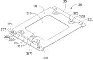
图3为本发明实施方式的安装支架的立体结构图。Fig. 3 is a three-dimensional structure diagram of the mounting bracket according to the embodiment of the present invention.
主要元件符号说明Description of main component symbols
如下具体实施方式将结合上述附图进一步说明本发明。The following specific embodiments will further illustrate the present invention in conjunction with the above-mentioned drawings.
具体实施方式Detailed ways
请参阅图1至图3,本发明实施方式的电子装置100包括主壳体10、装设于主壳体10上的安装支架30、固定件40及通过安装支架30稳固地装设于主壳体10内的存储部件50。在本实施方式中,电子装置100为电脑机箱,存储部件50为光驱、软驱、硬盘等对防震要求较高的存储部件。Please refer to FIG. 1 to FIG. 3 , an
主壳体10大致为矩形箱体状,其具有一个底壁11及一个由底壁11一端垂直延伸弯折而成的侧壁13。底壁11上沿平行于侧壁13方向间隔地凸设第一固定部113与第二固定部115。第一固定部113呈圆台状,其上开设有第一固定孔1131。第二固定部115呈大致三角台状,其三个角呈圆弧状,其上开设有第二固定孔1151。在第二固定孔1151侧旁设有一个起定位作用的圆凸起1153。凸设第一固定部113与第二固定部115主要为方便主壳体内放置安装其他电子器件。在本实施方式中,第一固定孔1131及第二固定孔1151为两个螺纹孔。侧壁13上靠近底壁11一侧对应第一固定部113与第二固定部115分别相对间隔地设有第一安装部133与第二安装部135。第一安装部133与第二安装部135呈大致矩形片状,沿垂直于侧壁13方向且朝向第一固定部113与第二固定部115一侧延伸弯折形成。第一安装部133边侧设有一个侧耳1333,其作用为定位。第一安装部133与第二安装部135上贯通开设有第一安装孔1331与第二安装孔1351,在本实施方式中,第一安装孔1331与第二安装孔1351为螺孔。The
安装支架30为一块通过冲压弯折而成的板状体,其可拆卸地装设于主壳体10上。安装支架30包括一个主体部31、两个支撑部33及两个固接部35。主体部31呈大致矩形板,其上大致中部位置处贯通开设有一个大致矩形的散热口313。主体部31的两端分别相互间隔地凸设有两个承载部315,存储部件50固定装设于承载部315上并位于主体部31上方。在本实施方式中,每个承载部315呈大致圆台状,四个承载部315分别凸设于主体部31的两端且邻近其四个角落位置处,主要是为了增加安装支架30的空间厚度,以加强其支撑存储部件50作用;每个承载部的中心位置处贯通开设有一个装配孔3151。主体部31的一端邻近散热口313位置处开设有一个与散热口313相通的缺口317,并对应于缺口317下方延伸弯折形成一个卡持部3171,用以卡嵌从主体部31下方穿越的连接线缆(图中未示)。The
两个支撑部33均为矩形条状,由主体部31的两端沿垂直于主体部31的方向朝向同一侧延伸弯折形成,并对应于主体部31的下方形成一大致为矩形的收容空间331。每个支撑部33上邻近主体部31两端的承载部315位置处间隔地贯通开设有两个条形通孔333。条形通孔333用于工艺上加工承载部315,并可增加支撑部33的整体弹性,以缓解装设于主体部31上的存储部件50受到的外力冲击及震动。The two supporting
两个固接部35均为矩形板状,其沿平行于主体部31方向分别相对设于该两个支撑部33的末端,由每个支撑部33的末端垂直延伸弯折形成,用以将安装支架30固定装设于主壳体10上。两个固接部35的两端对应主壳体10上的第一固定孔1131与第二固定孔1151及第一安装孔1331与第二安装孔1351分别贯通开设有固接孔351。为便于将安装支架30装设于主壳体10上,每个固接部35上还对应贯通开设有一个定位孔353。固接部35的两端对应这两个固接孔351的周缘分别凸设有两个与固接孔351同轴的中空圆柱形的缓冲台阶357。在本实施方式中,缓冲台阶357与固接部35的固接孔351一体形成,加工过程中通过将固接孔351反抽形成缓冲台阶357。The two
固定件40包括抵持部41及与抵持部41相连的配合部43。在本实施方式中,固定件40在本实施方式中为螺钉,抵持部41为螺钉的头部,配合部43上设置有螺纹,固定件40的数量与设于安装支架30上的装配孔3151及固接孔351的数量之和相当,用以将安装支架30与主壳体10及存储部件50相互固接。The
存储部件50固定装设于安装支架30的主体部31上,并通过安装支架30装设于主壳体10上。在本实施方式中,存储部件50为一个硬盘,其呈大致矩形块状,其上对应安装支架30上的装配孔3151开设有安装孔53。The
组装电子装置100时,先将存储部件50通过固定件40固定装设于安装支架30的主体部31上;存储部件50被水平放置于安装支架30的主体部31上,固定件40从主体部31的底部穿过承载部315的装配孔3151并对应固接于存储部件50的安装孔53上。接下来,将装设有存储部件50的安装支架30放置于主壳体10的底壁11上,其中,安装支架30的设有缓冲台阶357的固接部35的一端抵靠于主壳体10的底壁11的第一固定部113及第二固定部115上,另一个固接部35对应抵靠于主壳体10的侧壁13的第一安装部133与第二安装部135上。最后,将固定件40的末端穿过固接部35上的固接孔351并对应固接于主壳体10的第一固定孔1131与第二固定孔1151及第一安装孔1331与第二安装孔1351上,固定件抵持部41对应抵靠于缓冲台阶357上,即完成电子装置100的组装。在实际使用过程中,连接存储部件50与主壳体10内的其他存储部件之间的连接线缆可穿过并收容于安装支架30的主体部31下方,卡嵌于卡持部3171上。When assembling the
可以理解,所述反抽结构设计的缓冲台阶357并不限于设置于安装支架30的一个固接部35上的固接孔351上,其也可以仅在一个固接孔351或者在所有固接孔351上设置缓冲台阶357。It can be understood that the
电子装置100的安装支架30结构简单,其通过设置于安装支架30的一个固接部35的固接孔351周缘的缓冲台阶357,使得在安装过程中避免了固定件抵持部41与固接部35的直接接触。因此,防止了固定件40在使用过程中因受到震动而松动,使固定件40更加牢固地锁附于安装支架30的固接孔上,从而达到保护硬盘、光驱等存储部件50的目的。The mounting
以上说明对本发明而言只是说明性的,而非限制性的,本领域技术人员还可在本发明精神内做其它变化。当然,这些依据本发明精神所做的变化,都应包含在本发明所要求保护的范围内。The above description is only illustrative rather than restrictive to the present invention, and those skilled in the art can also make other changes within the spirit of the present invention. Of course, these changes made according to the spirit of the present invention should be included in the scope of the present invention.
Claims (10)
Priority Applications (3)
| Application Number | Priority Date | Filing Date | Title |
|---|---|---|---|
| CN2011100880690ACN102736681A (en) | 2011-04-08 | 2011-04-08 | Installation support and electron device employing therewith |
| TW100112880ATW201242490A (en) | 2011-04-08 | 2011-04-13 | Mounting bracket and electronic device using the same |
| US13/294,394US20120257334A1 (en) | 2011-04-08 | 2011-11-11 | Mounting bracket and electronic device using the same |
Applications Claiming Priority (1)
| Application Number | Priority Date | Filing Date | Title |
|---|---|---|---|
| CN2011100880690ACN102736681A (en) | 2011-04-08 | 2011-04-08 | Installation support and electron device employing therewith |
Publications (1)
| Publication Number | Publication Date |
|---|---|
| CN102736681Atrue CN102736681A (en) | 2012-10-17 |
Family
ID=46965965
Family Applications (1)
| Application Number | Title | Priority Date | Filing Date |
|---|---|---|---|
| CN2011100880690APendingCN102736681A (en) | 2011-04-08 | 2011-04-08 | Installation support and electron device employing therewith |
Country Status (3)
| Country | Link |
|---|---|
| US (1) | US20120257334A1 (en) |
| CN (1) | CN102736681A (en) |
| TW (1) | TW201242490A (en) |
Cited By (3)
| Publication number | Priority date | Publication date | Assignee | Title |
|---|---|---|---|---|
| CN104597981A (en)* | 2013-10-30 | 2015-05-06 | 鸿富锦精密工业(深圳)有限公司 | Hard disk holder and electronic device therewith |
| CN105141514A (en)* | 2015-07-24 | 2015-12-09 | 中南大学 | Intelligent gateway hardware system and realization method thereof |
| CN108541153A (en)* | 2018-04-29 | 2018-09-14 | 江苏恩达通用设备有限公司 | A kind of stable connection diesel engine monitor operations panel |
Families Citing this family (3)
| Publication number | Priority date | Publication date | Assignee | Title |
|---|---|---|---|---|
| CN104281227A (en)* | 2013-07-03 | 2015-01-14 | 鸿富锦精密工业(深圳)有限公司 | Storer fixing device |
| CN105744775B (en)* | 2014-12-08 | 2019-07-23 | 鸿富锦精密工业(深圳)有限公司 | Electronic device |
| JP7687091B2 (en)* | 2021-07-06 | 2025-06-03 | オムロン株式会社 | information display device |
Citations (3)
| Publication number | Priority date | Publication date | Assignee | Title |
|---|---|---|---|---|
| US20070125854A1 (en)* | 2005-07-08 | 2007-06-07 | Hon Hai Precision Industry Co., Ltd. | Mounting apparatus for card reader |
| US20090073649A1 (en)* | 2007-09-10 | 2009-03-19 | Aisin Aw Co., Ltd. | Disk device |
| CN101452321A (en)* | 2007-12-06 | 2009-06-10 | 鸿富锦精密工业(深圳)有限公司 | Hard disk rack |
- 2011
- 2011-04-08CNCN2011100880690Apatent/CN102736681A/enactivePending
- 2011-04-13TWTW100112880Apatent/TW201242490A/enunknown
- 2011-11-11USUS13/294,394patent/US20120257334A1/ennot_activeAbandoned
Patent Citations (3)
| Publication number | Priority date | Publication date | Assignee | Title |
|---|---|---|---|---|
| US20070125854A1 (en)* | 2005-07-08 | 2007-06-07 | Hon Hai Precision Industry Co., Ltd. | Mounting apparatus for card reader |
| US20090073649A1 (en)* | 2007-09-10 | 2009-03-19 | Aisin Aw Co., Ltd. | Disk device |
| CN101452321A (en)* | 2007-12-06 | 2009-06-10 | 鸿富锦精密工业(深圳)有限公司 | Hard disk rack |
Cited By (4)
| Publication number | Priority date | Publication date | Assignee | Title |
|---|---|---|---|---|
| CN104597981A (en)* | 2013-10-30 | 2015-05-06 | 鸿富锦精密工业(深圳)有限公司 | Hard disk holder and electronic device therewith |
| CN104597981B (en)* | 2013-10-30 | 2018-08-03 | 鸿富锦精密工业(深圳)有限公司 | Hard disk bracket and electronic device with the hard disk bracket |
| CN105141514A (en)* | 2015-07-24 | 2015-12-09 | 中南大学 | Intelligent gateway hardware system and realization method thereof |
| CN108541153A (en)* | 2018-04-29 | 2018-09-14 | 江苏恩达通用设备有限公司 | A kind of stable connection diesel engine monitor operations panel |
Also Published As
| Publication number | Publication date |
|---|---|
| TW201242490A (en) | 2012-10-16 |
| US20120257334A1 (en) | 2012-10-11 |
Similar Documents
| Publication | Publication Date | Title |
|---|---|---|
| US8094446B2 (en) | Bracket for mounting hard disk drive | |
| US8544801B2 (en) | Bracket assembly for disk drive | |
| US8537535B2 (en) | Data storage device cage | |
| US8248778B2 (en) | Fixing mechanism for storage device | |
| CN102736681A (en) | Installation support and electron device employing therewith | |
| US8206103B2 (en) | Fan assembly | |
| US8405968B2 (en) | Mounting apparatus for storage device | |
| US9345162B2 (en) | Mounting structure for circuit board | |
| US20130092807A1 (en) | Mounting apparatus for storage device | |
| US20150029656A1 (en) | Mounting apparatus for data storage device | |
| US20130315728A1 (en) | Fixing device for fan | |
| US8247707B2 (en) | Shielding assembly | |
| US8570721B2 (en) | Electronic device with interlatched front cover and back plate | |
| US20120305744A1 (en) | Fan mounting apparatus for heat dissipation | |
| US20140027604A1 (en) | Mounting apparatus for fan | |
| US8857925B2 (en) | Mounting bracket for power supply unit | |
| US20120169189A1 (en) | Electronic device enclosure | |
| US20130044453A1 (en) | Mounting apparatus for power supply | |
| US20130255987A1 (en) | Mounting device for fan | |
| US20130083459A1 (en) | Electronic assembly having retention device for data storage module | |
| US8717754B2 (en) | Hard disk drive mounting device | |
| CN102880258A (en) | Memory fixing device | |
| US20080017778A1 (en) | Mounting apparatus for data storage device | |
| US20120026655A1 (en) | Mounting apparatus for power supply unit | |
| US20150109726A1 (en) | Hard disk drive mounting device and electronic device using the same |
Legal Events
| Date | Code | Title | Description |
|---|---|---|---|
| C06 | Publication | ||
| PB01 | Publication | ||
| C10 | Entry into substantive examination | ||
| SE01 | Entry into force of request for substantive examination | ||
| C02 | Deemed withdrawal of patent application after publication (patent law 2001) | ||
| WD01 | Invention patent application deemed withdrawn after publication | Application publication date:20121017 |