CN102735348B - Wavefront measurement method based on Hartmann wavefront sensor - Google Patents
Wavefront measurement method based on Hartmann wavefront sensorDownload PDFInfo
- Publication number
- CN102735348B CN102735348BCN 201210198965CN201210198965ACN102735348BCN 102735348 BCN102735348 BCN 102735348BCN 201210198965CN201210198965CN 201210198965CN 201210198965 ACN201210198965 ACN 201210198965ACN 102735348 BCN102735348 BCN 102735348B
- Authority
- CN
- China
- Prior art keywords
- wavefront
- sub
- aberration
- aperture
- spot
- Prior art date
- Legal status (The legal status is an assumption and is not a legal conclusion. Google has not performed a legal analysis and makes no representation as to the accuracy of the status listed.)
- Expired - Fee Related
Links
- 238000000691measurement methodMethods0.000titleclaimsabstractdescription11
- 230000004075alterationEffects0.000claimsabstractdescription40
- 238000009826distributionMethods0.000claimsabstractdescription29
- 238000000034methodMethods0.000claimsabstractdescription14
- 238000004364calculation methodMethods0.000claimsabstractdescription4
- 201000009310astigmatismDiseases0.000claimsabstractdescription3
- 206010010071ComaDiseases0.000claimsdescription2
- 238000009827uniform distributionMethods0.000claimsdescription2
- 238000001514detection methodMethods0.000abstractdescription9
- 238000005259measurementMethods0.000description15
- 238000005516engineering processMethods0.000description9
- 230000003044adaptive effectEffects0.000description4
- 230000003287optical effectEffects0.000description3
- 230000009467reductionEffects0.000description3
- 238000003491arrayMethods0.000description2
- 238000010586diagramMethods0.000description2
- 239000006185dispersionSubstances0.000description2
- 230000008859changeEffects0.000description1
- 230000007812deficiencyEffects0.000description1
- 230000006872improvementEffects0.000description1
- 230000010354integrationEffects0.000description1
- 230000005693optoelectronicsEffects0.000description1
- 238000000614phase inversion techniqueMethods0.000description1
- 238000005070samplingMethods0.000description1
- 230000009466transformationEffects0.000description1
- 230000005428wave functionEffects0.000description1
Images

Landscapes
- Testing Of Optical Devices Or Fibers (AREA)
- Eye Examination Apparatus (AREA)
Abstract
Translated fromChinese
Description
Translated fromChinese技术领域technical field
本发明属于光学信息测量技术领域,涉及一种测量入射光束波前的方法,尤其涉及一种新型的基于哈特曼波前传感器的波前测量方法。The invention belongs to the technical field of optical information measurement, and relates to a method for measuring the wavefront of an incident light beam, in particular to a novel wavefront measurement method based on a Hartmann wavefront sensor.
背景技术Background technique
在自适应光学、光学检测、光电探测等应用领域,均需要测量光束的波前。尤其在自适应光学系统中,波前探测是自适应控制的一个重要前提,需要对波前信息进行快速测量,用于实时波前控制矫正。目前已经有许多种测量方法得到了实际应用,比如剪切干涉波前传感技术、哈特曼波前传感技术、曲率波前传感技术和相位反演法等。这些方法各自有其优缺点,被用于各种应用场合,其中哈特曼波前传感技术能同时测量两个方法的波前斜率,光能利用率较高;结构简单,可探测连续光或脉冲光,已经成为目前最流行、应用最广泛的波前传感技术。In adaptive optics, optical detection, photoelectric detection and other applications, it is necessary to measure the wavefront of the beam. Especially in adaptive optics systems, wavefront detection is an important prerequisite for adaptive control, which requires fast measurement of wavefront information for real-time wavefront control and correction. At present, many measurement methods have been applied in practice, such as shear interference wavefront sensing technology, Hartmann wavefront sensing technology, curvature wavefront sensing technology and phase inversion method, etc. These methods have their own advantages and disadvantages, and are used in various applications. Among them, the Hartmann wavefront sensing technology can measure the wavefront slope of the two methods at the same time, and the light energy utilization rate is high; the structure is simple, and it can detect continuous light. Or pulsed light, has become the most popular and widely used wavefront sensing technology.
典型的哈特曼波前传感器可以参见中国专利申请公开说明书(申请号98112210.8,公开号CN1245904)公开的一种光学波前传感器,其实现方式主要采用波前分割取样阵列元件如微透镜阵列,将波前分割成许多子孔径波前,并将入射的光分别汇聚到阵列型光电探测器上,一般采用CCD探测器或者CMOS探测器,阵列型光电探测器靶面上则形成一系列光斑阵列,通过各子光斑质心位置的计算处理获得所需波前相位测量数据。由于哈特曼波前传感器的广泛应用,提高哈特曼波前传感器波前测量精度已经成为一个研究热点。从结构上,可以通过适当增加子孔径数,增大对待测波面的采样率来提高测量精度;从信息探测上,可以使用高性能的阵列型光电探测器或者改进质心算法来提高质心的探测精度,参见“自适应系统中哈特曼波前传感器光斑质最佳标定位置”[马晓燠,郑翰清等.[J].光电工程,2009,36(4)];从复原算法上,可以通过改进复原算法,寻找实际应用中最优复原模式等方法提高复原算法的精度,参见“哈特曼夏克传感器的泽尼克模式波前复原误差”[李新阳,姜文汉.[J].光学学报,2002,22(10)]。上述提高哈特曼波前传感器测量精度的方法均将各子孔径内的波前视为只含倾斜像差的一阶平面,这一前提限制了哈特曼波前传感器精度进一步提升的空间及其在高精度测量中的应用。A typical Hartmann wavefront sensor can refer to a kind of optical wavefront sensor disclosed in the Chinese Patent Application Publication (Application No. 98112210.8, Publication No. CN1245904). The wavefront is divided into many sub-aperture wavefronts, and the incident light is respectively converged on the array photodetector. Generally, a CCD detector or a CMOS detector is used, and a series of spot arrays are formed on the target surface of the array photodetector. The required wavefront phase measurement data is obtained by calculating the centroid position of each sub-spot. Due to the wide application of Hartmann wavefront sensors, improving the wavefront measurement accuracy of Hartmann wavefront sensors has become a research hotspot. In terms of structure, the measurement accuracy can be improved by appropriately increasing the number of sub-apertures and increasing the sampling rate of the wave surface to be measured; in terms of information detection, high-performance array photodetectors or improved centroid algorithms can be used to improve the detection accuracy of the centroid , see "The Best Calibration Position of Hartmann Wavefront Sensor Light Spot Quality in Adaptive System" [Ma Xiaoyu, Zheng Hanqing, etc. [J]. Optoelectronic Engineering, 2009, 36(4)]; from the restoration algorithm, it can be restored by improving Algorithm, finding the optimal restoration mode in practical applications and other methods to improve the accuracy of the restoration algorithm, see "Zernik mode wavefront restoration error of Hartmann Shack sensor" [Li Xinyang, Jiang Wenhan. [J]. Acta Optics Sinica, 2002, 22(10)]. The above-mentioned methods for improving the measurement accuracy of the Hartmann wavefront sensor regard the wavefront in each sub-aperture as a first-order plane containing only oblique aberrations. This premise limits the space for further improvement of the accuracy of the Hartmann wavefront sensor. Its application in high-precision measurement.
Shane Barwick提出的用一种像散混合波前传感器同时测量子孔径内波面一阶斜率和二次曲率,参见“Detecting higher-order wavefronterrors with an astigmatic hybrid wavefront sensor”[ShaneBarwick.[J].OPTICS LETTERS,2009,34(11)],该方法要求微透镜中每个透镜均保留一定量的像散像差,且采用四象限探测器阵列探测光斑阵列,制造工艺复杂,难以实现,这限制了其推广与实际应用。Shane Barwick proposed to use an astigmatic hybrid wavefront sensor to simultaneously measure the first-order slope and quadratic curvature of the sub-aperture wavefront, see "Detecting higher-order wavefronterrors with an astigmatic hybrid wavefront sensor" [ShaneBarwick.[J].OPTICS LETTERS . promotion and practical application.
发明内容Contents of the invention
为了克服现有技术的不足,突破了将哈特曼子孔径内波前视为一阶平面的思维定势,为此,本发明的目的是提供一种基于哈特曼波前传感器的波前测量方法,将原本困扰光斑质心计算的光斑弥散信息充分利用,获取子孔径内波面的更多细节信息,进而使整个波前测量精度得到质的提升。In order to overcome the deficiencies in the prior art, it has broken through the thinking pattern of considering the wavefront in the Hartmann sub-aperture as a first-order plane. For this reason, the purpose of the invention is to provide a wavefront sensor based on Hartmann The measurement method makes full use of the spot dispersion information that originally troubled the calculation of the spot centroid, and obtains more detailed information of the wavefront in the sub-aperture, thereby qualitatively improving the measurement accuracy of the entire wavefront.
为实现所述目的,本发明提供一种基于哈特曼波前传感器的波前测量方法,该方法基于普通哈特曼波前传感器的结构,其特征在于通过以下步骤实现波前测量:For realizing said purpose, the present invention provides a kind of wavefront measurement method based on Hartmann wavefront sensor, this method is based on the structure of common Hartmann wavefront sensor, it is characterized in that realize wavefront measurement by following steps:
步骤S1:用无像差理想平面光源对哈特曼波前传感器进行定标,得到无像差光波入射时阵列型光电探测器靶面上的远场光斑阵列图像作为定标基准图像,并计算定标基准图像上各个光斑质心的初始位置;Step S1: Use the aberration-free ideal planar light source to calibrate the Hartmann wavefront sensor, and obtain the far-field spot array image on the target surface of the array photodetector when the aberration-free light wave is incident as the calibration reference image, and calculate Calibrate the initial position of each spot centroid on the reference image;
步骤S2:含有波前像差的待测光波入射到哈特曼波前传感器并在阵列型光电探测器靶面上形成远场光斑阵列图像,根据带波前像差光波入射条件下获取的远场光斑阵列图像,计算带波前像差光波入射条件下获取的各个远场光斑的质心位置相对于定标基准图像上各个光斑质心的初始位置的远场光斑的质心偏移量,并记录带波前像差光波入射条件下获取的各个远场光斑的光强分布信息;Step S2: The light wave to be measured with wavefront aberration enters the Hartmann wavefront sensor and forms a far-field spot array image on the target surface of the array photodetector. Field spot array image, calculate the centroid position of each far-field spot obtained under the incident condition of light wave with wavefront aberration relative to the initial position of the center of mass of each spot on the calibration reference image, and record with The light intensity distribution information of each far-field spot obtained under the incident condition of wavefront aberration light wave;
步骤S3:利用远场光斑的质心偏移量,求出对应哈特曼波前传感器各子孔径内子波前的倾斜像差分量或一阶斜率信息;Step S3: Using the centroid offset of the far-field spot, obtain the oblique aberration component or first-order slope information of the sub-wavefronts corresponding to each sub-aperture of the Hartmann wavefront sensor;
步骤S4:利用远场光斑的光强分布信息,结合已测得的子波前的倾斜像差分量或一阶斜率,通过相位反演算法恢复各子孔径内波前多个细节信息,获得对应的哈特曼波前传感器子孔径内由倾斜、离焦等高阶像差分量构成的或是由一次平面、二次曲面等高次曲面分量组成的子波前;Step S4: Using the light intensity distribution information of the far-field spot, combined with the measured oblique aberration component or first-order slope of the sub-wavefront, recover multiple detailed information of the wavefront in each sub-aperture through the phase inversion algorithm, and obtain the corresponding The sub-aperture of the Hartmann wavefront sensor is composed of high-order aberration components such as tilt and defocus, or sub-wavefronts composed of high-order surface components such as first-order planes and quadratic surfaces;
步骤S5:用波前复原算法或是拼接方法将步骤S4中获得的各子孔径内子波前重构成整个全孔径待测光波的波前像差。Step S5: Reconstruct the sub-wavefronts in each sub-aperture obtained in step S4 into the wavefront aberration of the entire full-aperture light wave to be measured by using the wavefront restoration algorithm or splicing method.
本发明与现有技术相比有如下优点:不再简单的将哈特曼波前传感器各子孔径内波前视为只含倾斜像差分量或是一阶平面,将哈特曼波前传感器技术与目前比较成熟的相位反演技术相结合,在哈特曼波前传感器中的阵列型光电探测器采集到光斑阵列图像后,计算各光斑质心偏移并记录各光斑的光强分布信息,使原本影响各子光斑质心探测精度的子光斑弥散分布信息得以利用,在利用光斑质心偏移量复原各个子孔径内波前的倾斜像差或是一阶斜率的同时根据各光斑的光强分布提取对应子孔径内子波前的更多细节信息,从而提高波前测量结果的精度;本发明大大缓解了哈特曼波前传感器的测量精度严重受限于子孔径排布密度的情况,与现有技术相比,能够在相同子孔径数下,进一步提高波前测量精度,或者即使在减少一定量的子孔径的情况下,也能保证一定的测量精度。本发明不改变哈特曼波前传感器的结构,充分利用哈特曼波前传感器系统的信息量,继承了其光能利用率高、可测连续或脉冲光等一系列优点,同时将困扰光斑质心探测的光斑弥散信息加以利用,能够有效提高波前测量精度,可被应用于高精度波前探测相关领域。Compared with the prior art, the present invention has the following advantages: the wavefront in each sub-aperture of the Hartmann wavefront sensor is no longer simply regarded as only containing the oblique aberration component or the first-order plane, but the Hartmann wavefront sensor The technology is combined with the relatively mature phase inversion technology at present. After the array photodetector in the Hartmann wavefront sensor collects the spot array image, it calculates the centroid shift of each spot and records the light intensity distribution information of each spot. The sub-spot diffuse distribution information that originally affects the centroid detection accuracy of each sub-spot can be used. While using the spot centroid offset to restore the oblique aberration or first-order slope of the wavefront in each sub-aperture, according to the light intensity distribution of each spot Extract more detailed information of the sub-wavefront in the corresponding sub-aperture, thereby improving the accuracy of the wavefront measurement result; the present invention greatly alleviates the situation that the measurement accuracy of the Hartmann wavefront sensor is severely limited by the arrangement density of sub-apertures, which is different from the existing Compared with existing technologies, the wavefront measurement accuracy can be further improved under the same number of sub-apertures, or a certain measurement accuracy can be guaranteed even when a certain amount of sub-apertures is reduced. The invention does not change the structure of the Hartmann wavefront sensor, fully utilizes the information volume of the Hartmann wavefront sensor system, inherits a series of advantages such as high utilization rate of light energy, and can measure continuous or pulsed light, and at the same time, will trouble the light spot Utilizing the spot dispersion information of centroid detection can effectively improve the accuracy of wavefront measurement and can be applied to high-precision wavefront detection related fields.
附图说明Description of drawings
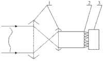
图1为本发明的典型的哈特曼波前传感器装置示意图;Fig. 1 is a typical Hartmann wavefront sensor device schematic diagram of the present invention;
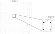
图2为本发明中哈特曼波前传感器工作时待测光波在阵列型光电探测器靶面上形成光斑阵列示意图;Fig. 2 is the schematic diagram of spot array formed by the light wave to be measured on the array type photodetector target surface when the Hartmann wavefront sensor works in the present invention;
图3为本发明的基于哈特曼波前传感器波前测量方法;Fig. 3 is based on Hartmann's wavefront sensor wavefront measurement method of the present invention;
具体实施方式Detailed ways
为使本发明的目的、技术方案和优点更加清楚明白,以下结合具体实施例,并参照附图,对本发明进一步详细说明。In order to make the object, technical solution and advantages of the present invention clearer, the present invention will be described in further detail below in conjunction with specific embodiments and with reference to the accompanying drawings.
图1是基于哈特曼波前传感器波前测量方法的具体步骤包括:Fig. 1 is based on the specific steps of Hartmann's wavefront sensor wavefront measurement method including:
步骤S1:用无像差理想平面光源对哈特曼波前传感器进行定标,得到无像差光波入射时阵列型光电探测器3(图2示出)靶面上的远场光斑阵列图像作为定标基准图像,并计算定标基准图像上各个光斑质心的初始位置;Step S1: Use an aberration-free ideal planar light source to calibrate the Hartmann wavefront sensor, and obtain the far-field spot array image on the target surface of the array photodetector 3 (shown in FIG. 2 ) when the aberration-free light wave is incident as Calibrate the reference image, and calculate the initial position of each spot centroid on the calibration reference image;
步骤S2:含有波前像差的待测光波入射到哈特曼波前传感器并在其阵列型光电探测器3靶面上形成远场光斑阵列图像,根据带波前像差光波入射条件下获取的远场光斑阵列图像,计算带波前像差光波入射条件下获取的各个远场光斑的质心位置相对于定标基准图像上各个光斑质心的初始位置的远场光斑的质心偏移量,并记录带波前像差光波入射条件下获取的各个远场光斑的光强分布信息;Step S2: The light wave to be measured with wavefront aberration is incident on the Hartmann wavefront sensor and forms a far-field spot array image on the target surface of its
步骤S3:利用远场光斑的质心偏移量,求出对应哈特曼波前传感器各子孔径内子波前的倾斜像差分量或一阶斜率信息;Step S3: Using the centroid offset of the far-field spot, obtain the oblique aberration component or first-order slope information of the sub-wavefronts corresponding to each sub-aperture of the Hartmann wavefront sensor;
步骤S4:利用远场光斑的光强分布信息,结合已测得的子波前的倾斜像差分量或一阶斜率,通过相位反演算法恢复各子孔径内波前多个细节信息,获得对应的哈特曼波前传感器子孔径内由倾斜、离焦等高阶像差分量构成的或是由一次平面、二次曲面等高次曲面分量组成的子波前;Step S4: Using the light intensity distribution information of the far-field spot, combined with the measured oblique aberration component or first-order slope of the sub-wavefront, recover multiple detailed information of the wavefront in each sub-aperture through the phase inversion algorithm, and obtain the corresponding The sub-aperture of the Hartmann wavefront sensor is composed of high-order aberration components such as tilt and defocus, or sub-wavefronts composed of high-order surface components such as first-order planes and quadratic surfaces;
步骤S5:用波前拼接方法,以位于顶角位置(如左上角)的子孔径为起始,将步骤S4中获得的各子孔径内子波前依次首尾链接拼接,重构成整个全孔径待测光波的波前像差。Step S5: Using the wavefront splicing method, start with the sub-aperture located at the top corner position (such as the upper left corner), and splice the sub-wavefronts in each sub-aperture obtained in step S4 sequentially end-to-end to reconstruct the entire full-aperture to be tested Wavefront aberration of light waves.
步骤S4中的相位反演算法要求只需单幅远场光强分布图像就能获得近场相位分布,所述相位反演算法可以是GS算法。GS算法步骤可概况为:The phase inversion algorithm in step S4 requires only a single far-field light intensity distribution image to obtain the near-field phase distribution, and the phase inversion algorithm may be a GS algorithm. The steps of GS algorithm can be summarized as follows:
①先给定子孔径内的初始相位分布为步骤S3求得的子孔径内倾斜像差分量,并假设子孔径内光波振幅分布|F(x,y)|为均匀常数,从而构成入射光波复振幅其中x、y分布表示子孔径所在空间横坐标和纵坐标;表示以自然对数e为底的指数函数形式,其中j表述纯虚数,值为
②对En(x,y)作傅里叶变换得到Ef(u,v)=g(u,v)*ejφ(u,v),其中u、v分布表示远场空间横纵坐标;Ef(u,v)表示En(x,y)的傅里叶变换形式;g(u,v)表示Ef(u,v)中的整幅分布;φ(u,v)表示Ef(u,v)中的相位分布。② Perform Fourier transform on En (x, y) to get Ef (u, v) = g (u, v) * ejφ (u, v), where the distribution of u and v represent the horizontal and vertical coordinates of the far field space ; Ef (u, v) means the Fourier transform form of En (x, y); g (u, v) means the entire distribution in Ef (u, v); φ (u, v) means Phase distribution inEf (u,v).
③用Ef(u,v)的相位分布部分φ(u,v)与获得的远场光斑光强分布根方值(即远处光波振幅)G(u,v)构成函数Ef′(u,v)=G(u,v)*ejφ(u,v);③ Use the phase distribution part φ(u, v) of Ef (u, v) and the root square value of the obtained far-field spot light intensity distribution (that is, the far-field light wave amplitude) G(u, v) to form a function Ef ′( u, v) = G(u, v)*ejφ (u, v);
④对Ef′(u,v)作傅里叶变换得到下一步迭代光波函数E′n(x,y);重复以上步骤直至均方根SSE小于预先规定的精度控制指标ε:④ Perform Fourier transform on Ef ′(u, v) to obtain the next iterative light wave function E′n (x, y); repeat the above steps until the root mean square SSE is less than the pre-specified precision control index ε:
SSE=[∫∫(g(u,v)-G(u,v))2dudv]/[∫∫G(u,v)2dudv]<ε。SSE=[∫∫(g(u,v)−G(u,v))2 dudv]/[∫∫G(u,v)2 dudv]<ε.
此时得到的
步骤S4中的子孔径内波前多个细节信息是从像差角度上看的较倾斜像差更高阶的像差信息,所述像差信息是离焦、像散、慧差和球差信息,或是从空间曲面角度上看的较一阶斜率更高次的曲率信息,所述曲率信息是二次曲率、三次曲率和四次曲率信息。The multiple detailed information of the wavefront in the sub-aperture in step S4 is aberration information of a higher order than oblique aberration viewed from the perspective of aberration, and the aberration information is defocus, astigmatism, coma and spherical aberration information, or curvature information of a higher order than the first-order slope from the perspective of a space surface, and the curvature information is quadratic curvature, cubic curvature, and quartic curvature information.
用单幅远场子光斑光强分布图像复原近场子孔径内子波前相位时所用的相位反演算法,是将近场子孔径内光波振幅为均匀分布作为反演计算的前提条件。The phase inversion algorithm used when using a single far-field sub-spot light intensity distribution image to restore the sub-wavefront phase in the near-field sub-aperture is to use the uniform distribution of light wave amplitude in the near-field sub-aperture as the prerequisite for inversion calculation.
如图2所示,典型的哈特曼波前传感器,主要由缩束系统1、微透镜阵列2和阵列型光电探测器3为CMOS探测器组成,其中缩束系统1由两个焦距和口径均不同的凸透镜共轴放置构成,焦距长口径大的凸透镜在前,焦距短口径小的凸透镜在后,前一个透镜的后焦面与后一个透镜的前焦面重合,缩束系统1主要将入射光束的尺寸缩小到与微透镜阵列2口径匹配,即缩束后光束的尺寸小于微透镜阵列2的口径,微透镜阵列2由16×16个微透镜排列构成,置于缩束系统1之后,每个微透镜将光波分割并分别聚焦到位于其焦面的阵列型光电探测器3为CMOS探测器上,因此入射平行光在通过缩束系统1并经过微透镜阵列2之后,成像在阵列型光电探测器3为CMOS探测器的靶面上形成光斑阵列图像,如图3所示,其中每一个光斑并非一个光点,均带有一定量的弥散分布信息。本方法利用上述哈特曼波前传感器中阵列型光电探测器3为CMOS探测器获取的光斑阵列图像,计算各光斑质心偏移并记录各光斑的光强分布信息,哈特曼波前传感器每个子孔径内波前不再被视为只含倾斜像差的平面,在利用光斑质心偏移量复原各个子孔径内波前的倾斜像差或是一阶斜率的同时根据各光斑的光强分布提取对应子孔径内子波前的更多细节信息,进而提高波前测量结果的精度。As shown in Figure 2, a typical Hartmann wavefront sensor is mainly composed of a beam shrinking system 1, a
以上所述,仅为本发明中的具体实施方式,但本发明的保护范围并不局限于此,任何熟悉该技术的人在本发明所揭露的技术范围内,可理解想到的变换或替换,都应涵盖在本发明的包含范围之内。The above is only a specific implementation mode in the present invention, but the scope of protection of the present invention is not limited thereto. Anyone familiar with the technology can understand the conceivable transformation or replacement within the technical scope disclosed in the present invention. All should be covered within the scope of the present invention.
Claims (4)
Translated fromChinesePriority Applications (1)
| Application Number | Priority Date | Filing Date | Title |
|---|---|---|---|
| CN 201210198965CN102735348B (en) | 2012-06-15 | 2012-06-15 | Wavefront measurement method based on Hartmann wavefront sensor |
Applications Claiming Priority (1)
| Application Number | Priority Date | Filing Date | Title |
|---|---|---|---|
| CN 201210198965CN102735348B (en) | 2012-06-15 | 2012-06-15 | Wavefront measurement method based on Hartmann wavefront sensor |
Publications (2)
| Publication Number | Publication Date |
|---|---|
| CN102735348A CN102735348A (en) | 2012-10-17 |
| CN102735348Btrue CN102735348B (en) | 2013-07-24 |
Family
ID=46991256
Family Applications (1)
| Application Number | Title | Priority Date | Filing Date |
|---|---|---|---|
| CN 201210198965Expired - Fee RelatedCN102735348B (en) | 2012-06-15 | 2012-06-15 | Wavefront measurement method based on Hartmann wavefront sensor |
Country Status (1)
| Country | Link |
|---|---|
| CN (1) | CN102735348B (en) |
Cited By (1)
| Publication number | Priority date | Publication date | Assignee | Title |
|---|---|---|---|---|
| CN115165124A (en)* | 2022-07-05 | 2022-10-11 | 重庆连芯智能科技研究院有限公司 | A Correlation Hartmann Fast Wavefront Restoration Method |
Families Citing this family (26)
| Publication number | Priority date | Publication date | Assignee | Title |
|---|---|---|---|---|
| CN102980743B (en)* | 2012-10-26 | 2015-02-11 | 中国人民解放军国防科学技术大学 | Full light path aberration correction system and full light path aberration correction method based on double Hartmann sensors |
| CN102967380B (en)* | 2012-12-09 | 2014-10-29 | 中国科学院光电技术研究所 | Hartmann wavefront sensor based on unit photosensitive detector array |
| CN103335950B (en)* | 2013-06-24 | 2015-02-25 | 中国科学院光电技术研究所 | Device and method for measuring atmospheric turbulence non-isoplanatic wavefront error and turbulence characteristic parameters |
| CN104215339B (en)* | 2014-09-14 | 2017-02-15 | 中国科学院光电技术研究所 | Wavefront restoration system and method based on continuous far field |
| CN104239740B (en)* | 2014-09-26 | 2018-04-13 | 中国科学院光电技术研究所 | Mode wavefront restoration method based on Hartmann wavefront sensor |
| CN104266769B (en)* | 2014-10-23 | 2017-03-22 | 北京理工大学 | Phase recovering method |
| CN105606211B (en)* | 2015-09-11 | 2017-07-11 | 北京理工大学 | In-orbit Zero positioning method for related Hartmann shark wavefront sensor |
| CN106441084B (en)* | 2016-11-21 | 2019-02-01 | 深圳大学 | Wavefront sensor, wavefront sensing methods and system based on micro- hologram array |
| CN106768892A (en)* | 2016-12-28 | 2017-05-31 | 中国计量大学 | Free surface lens corrugated joining method based on Hartmann shark wavefront sensor |
| CN107525654B (en)* | 2017-08-23 | 2024-06-11 | 重庆连芯智能科技研究院有限公司 | Imaging system aberration detection method and device |
| CN108692820B (en)* | 2018-05-23 | 2019-11-29 | 马晓燠 | A kind of Wavefront measuring apparatus and method |
| WO2020019204A1 (en)* | 2018-07-25 | 2020-01-30 | 合刃科技(深圳)有限公司 | System and method for detecting stealthy object |
| CN108775965B (en)* | 2018-08-07 | 2019-11-12 | 中国工程物理研究院激光聚变研究中心 | A kind of wavefront measuring method |
| CN109186956B (en)* | 2018-09-11 | 2020-10-30 | 中国工程物理研究院激光聚变研究中心 | Transient wavefront distortion measuring method for online condition of beam shaping element |
| CN110361163B (en)* | 2019-06-14 | 2021-06-04 | 中科院南京天文仪器有限公司 | Device and method for detecting large-caliber optical system by parallel light tube suspension scanning |
| CN110567681B (en)* | 2019-09-26 | 2021-02-12 | 中国科学院长春光学精密机械与物理研究所 | A device and method for detecting a non-common field of view self-collimating optical system |
| CN110631716B (en)* | 2019-09-29 | 2021-09-21 | 中国科学院光电技术研究所 | A compact Hartmann wavefront sensor |
| CN112097923B (en)* | 2020-07-30 | 2022-05-24 | 福建华科光电有限公司 | Simple wavefront measurement method for optical element |
| CN111829671B (en)* | 2020-09-08 | 2023-01-03 | 中国工程物理研究院应用电子学研究所 | High-resolution wavefront detection device and wavefront restoration method |
| CN112179503A (en)* | 2020-09-27 | 2021-01-05 | 中国科学院光电技术研究所 | Deep learning wavefront restoration method based on sparse subaperture shack-Hartmann wavefront sensor |
| CN112414565B (en)* | 2020-12-02 | 2021-09-21 | 中国人民解放军国防科技大学 | Large-field-of-view wavefront measuring device, method, equipment and medium |
| CN112729570B (en)* | 2020-12-16 | 2022-04-19 | 航天科工微电子系统研究院有限公司 | Wavefront sensor based on directional modulation microlens array and wavefront detection method |
| CN113776679B (en)* | 2021-08-26 | 2022-08-23 | 浙江大学 | Misregistration deviation compensation method for shack Hartmann wavefront sensor |
| CN114544008B (en)* | 2022-02-21 | 2025-09-12 | 中国科学技术大学 | A wavefront restoration method, system, device and storage medium |
| CN114858290B (en)* | 2022-05-25 | 2025-08-22 | 广东粤港澳大湾区黄埔材料研究院 | A high-sensitivity waveform reconstruction method and device |
| CN116412917B (en)* | 2023-03-20 | 2025-08-01 | 中国科学院光电技术研究所 | Dual-sight light spot centroid calculation method based on centroid offset |
Citations (3)
| Publication number | Priority date | Publication date | Assignee | Title |
|---|---|---|---|---|
| WO2003062743A1 (en)* | 2002-01-24 | 2003-07-31 | Nano-Or Technologies (Israel) Ltd. | Improved spatial wavefront analysis and 3d measurement |
| TW200741185A (en)* | 2005-12-13 | 2007-11-01 | Agency Science Tech & Res | Optical wavefront sensor |
| CN102095503A (en)* | 2010-11-30 | 2011-06-15 | 中国科学院国家天文台南京天文光学技术研究所 | Wavefront detection and reconstruction method based on differential sensor |
Family Cites Families (1)
| Publication number | Priority date | Publication date | Assignee | Title |
|---|---|---|---|---|
| FR2827380B1 (en)* | 2001-07-12 | 2003-11-07 | Imagine Optic | DEVICE FOR ANALYZING A WAVEFRONT WITH IMPROVED RESOLUTION |
- 2012
- 2012-06-15CNCN 201210198965patent/CN102735348B/ennot_activeExpired - Fee Related
Patent Citations (3)
| Publication number | Priority date | Publication date | Assignee | Title |
|---|---|---|---|---|
| WO2003062743A1 (en)* | 2002-01-24 | 2003-07-31 | Nano-Or Technologies (Israel) Ltd. | Improved spatial wavefront analysis and 3d measurement |
| TW200741185A (en)* | 2005-12-13 | 2007-11-01 | Agency Science Tech & Res | Optical wavefront sensor |
| CN102095503A (en)* | 2010-11-30 | 2011-06-15 | 中国科学院国家天文台南京天文光学技术研究所 | Wavefront detection and reconstruction method based on differential sensor |
Non-Patent Citations (1)
| Title |
|---|
| Ping Yang,Shuai Wang等.A Novel Wavefront Sensing Technique for High Speed Atmospheric Measurement Based on Digital Micromirror Device.《Proc.of SPIE》.2011,第8178卷81780N-1到81780N-9.* |
Cited By (1)
| Publication number | Priority date | Publication date | Assignee | Title |
|---|---|---|---|---|
| CN115165124A (en)* | 2022-07-05 | 2022-10-11 | 重庆连芯智能科技研究院有限公司 | A Correlation Hartmann Fast Wavefront Restoration Method |
Also Published As
| Publication number | Publication date |
|---|---|
| CN102735348A (en) | 2012-10-17 |
Similar Documents
| Publication | Publication Date | Title |
|---|---|---|
| CN102735348B (en) | Wavefront measurement method based on Hartmann wavefront sensor | |
| CN102252832B (en) | Large aperture collimation system wavefront quality detection device and method | |
| CN111221132B (en) | Method and device for measuring vortex beam topological charge number by fan-shaped sub-aperture micro-lens array | |
| CN104596650A (en) | Hartmann wavefront sensor super-resolution wavefront restoration method | |
| CN104239740B (en) | Mode wavefront restoration method based on Hartmann wavefront sensor | |
| CN103557947B (en) | A kind of self-aligning double mode Wavefront sensor and measuring method | |
| CN101344434B (en) | Adaptive calibration device for Hartmann wavefront sensor based on four-quadrant detector | |
| CN106338823B (en) | Phase inversion method based on mixed focal length Fresnel zone plate | |
| CN101936779B (en) | Double-optical-wedge spliced rectangular pyramid wavefront sensor | |
| CN102749143A (en) | Wavefront reconstruction method for improving measurement accuracy of shack-Hartmann wavefront sensor | |
| CN102914373A (en) | Hartmann wave-front sensor based on micro-cylindrical lens array | |
| CN102589720B (en) | Hartmann wavefront measuring instrument suitable for non-uniform light illumination | |
| CN109520625A (en) | A kind of Wavefront sensor | |
| CN102721476B (en) | Large-caliber high-speed infrared laser measuring device based on PSD array | |
| CN105466576A (en) | Device and method for synchronously measuring height and angle non-isohalo wavefront errors of atmospheric turbulence | |
| CN101285712B (en) | Linear phase inversion wavefront sensor based on discrete light intensity measuring device | |
| CN102967379B (en) | Wavefront sensor for solar self-adaptive optical system | |
| CN102507019A (en) | Hartmann wavefront sensor based on micro-scanning for image quality detection | |
| CN103105235B (en) | Method for measuring oblique aberration in sub-aperture of Hartmann wavefront sensor | |
| CN101285735B (en) | A Hartmann sensor that expands the dynamic range by separating the overall tilt of the wavefront | |
| CN112229528B (en) | Hartmann wavefront sensor based on Fermat spiral self-interference multifocal lens array | |
| CN101285711A (en) | Linear phase inversion wavefront sensor based on area array CCD | |
| CN104266769B (en) | Phase recovering method | |
| CN111998962A (en) | Hartmann wavefront sensor based on array type binary phase modulation | |
| CN116187395A (en) | Blocking mirror translation and inclination error detection method based on convolutional neural network |
Legal Events
| Date | Code | Title | Description |
|---|---|---|---|
| C06 | Publication | ||
| PB01 | Publication | ||
| C10 | Entry into substantive examination | ||
| SE01 | Entry into force of request for substantive examination | ||
| C14 | Grant of patent or utility model | ||
| GR01 | Patent grant | ||
| CF01 | Termination of patent right due to non-payment of annual fee | ||
| CF01 | Termination of patent right due to non-payment of annual fee | Granted publication date:20130724 |