CN102727329A - Artificial cervical intervertebral disc - Google Patents
Artificial cervical intervertebral discDownload PDFInfo
- Publication number
- CN102727329A CN102727329ACN2012102177488ACN201210217748ACN102727329ACN 102727329 ACN102727329 ACN 102727329ACN 2012102177488 ACN2012102177488 ACN 2012102177488ACN 201210217748 ACN201210217748 ACN 201210217748ACN 102727329 ACN102727329 ACN 102727329A
- Authority
- CN
- China
- Prior art keywords
- arc
- vertebral pulp
- vertebral
- nucleus pulposus
- cervical
- Prior art date
- Legal status (The legal status is an assumption and is not a legal conclusion. Google has not performed a legal analysis and makes no representation as to the accuracy of the status listed.)
- Granted
Links
- 230000033001locomotionEffects0.000claimsabstractdescription10
- 238000005452bendingMethods0.000claimsabstractdescription8
- RTAQQCXQSZGOHL-UHFFFAOYSA-NTitaniumChemical compound[Ti]RTAQQCXQSZGOHL-UHFFFAOYSA-N0.000claimsdescription5
- 230000009471actionEffects0.000claimsdescription5
- 210000000988bone and boneAnatomy0.000claimsdescription5
- 229910052588hydroxylapatiteInorganic materials0.000claimsdescription5
- XYJRXVWERLGGKC-UHFFFAOYSA-Dpentacalcium;hydroxide;triphosphateChemical compound[OH-].[Ca+2].[Ca+2].[Ca+2].[Ca+2].[Ca+2].[O-]P([O-])([O-])=O.[O-]P([O-])([O-])=O.[O-]P([O-])([O-])=OXYJRXVWERLGGKC-UHFFFAOYSA-D0.000claimsdescription5
- 230000005484gravityEffects0.000claimsdescription4
- 230000009977dual effectEffects0.000claims2
- 230000035479physiological effects, processes and functionsEffects0.000claims2
- 238000004088simulationMethods0.000claims2
- 238000005507sprayingMethods0.000claims2
- 229910052719titaniumInorganic materials0.000claims2
- 239000010936titaniumSubstances0.000claims2
- 230000003044adaptive effectEffects0.000claims1
- 230000035790physiological processes and functionsEffects0.000abstractdescription10
- 230000006870functionEffects0.000abstractdescription7
- 230000007659motor functionEffects0.000abstractdescription2
- 230000000903blocking effectEffects0.000description7
- 238000010586diagramMethods0.000description3
- 238000000034methodMethods0.000description2
- 230000007547defectEffects0.000description1
- 230000007774longtermEffects0.000description1
- 238000012986modificationMethods0.000description1
- 230000004048modificationEffects0.000description1
- 230000001737promoting effectEffects0.000description1
Images


Classifications
- A—HUMAN NECESSITIES
- A61—MEDICAL OR VETERINARY SCIENCE; HYGIENE
- A61F—FILTERS IMPLANTABLE INTO BLOOD VESSELS; PROSTHESES; DEVICES PROVIDING PATENCY TO, OR PREVENTING COLLAPSING OF, TUBULAR STRUCTURES OF THE BODY, e.g. STENTS; ORTHOPAEDIC, NURSING OR CONTRACEPTIVE DEVICES; FOMENTATION; TREATMENT OR PROTECTION OF EYES OR EARS; BANDAGES, DRESSINGS OR ABSORBENT PADS; FIRST-AID KITS
- A61F2/00—Filters implantable into blood vessels; Prostheses, i.e. artificial substitutes or replacements for parts of the body; Appliances for connecting them with the body; Devices providing patency to, or preventing collapsing of, tubular structures of the body, e.g. stents
- A61F2/02—Prostheses implantable into the body
- A61F2/30—Joints
- A61F2/44—Joints for the spine, e.g. vertebrae, spinal discs
- A—HUMAN NECESSITIES
- A61—MEDICAL OR VETERINARY SCIENCE; HYGIENE
- A61F—FILTERS IMPLANTABLE INTO BLOOD VESSELS; PROSTHESES; DEVICES PROVIDING PATENCY TO, OR PREVENTING COLLAPSING OF, TUBULAR STRUCTURES OF THE BODY, e.g. STENTS; ORTHOPAEDIC, NURSING OR CONTRACEPTIVE DEVICES; FOMENTATION; TREATMENT OR PROTECTION OF EYES OR EARS; BANDAGES, DRESSINGS OR ABSORBENT PADS; FIRST-AID KITS
- A61F2/00—Filters implantable into blood vessels; Prostheses, i.e. artificial substitutes or replacements for parts of the body; Appliances for connecting them with the body; Devices providing patency to, or preventing collapsing of, tubular structures of the body, e.g. stents
- A61F2/02—Prostheses implantable into the body
- A61F2/30—Joints
- A61F2002/30001—Additional features of subject-matter classified in A61F2/28, A61F2/30 and subgroups thereof
Landscapes
- Health & Medical Sciences (AREA)
- Orthopedic Medicine & Surgery (AREA)
- Engineering & Computer Science (AREA)
- Biomedical Technology (AREA)
- Heart & Thoracic Surgery (AREA)
- Cardiology (AREA)
- Oral & Maxillofacial Surgery (AREA)
- Transplantation (AREA)
- Neurology (AREA)
- Vascular Medicine (AREA)
- Life Sciences & Earth Sciences (AREA)
- Animal Behavior & Ethology (AREA)
- General Health & Medical Sciences (AREA)
- Public Health (AREA)
- Veterinary Medicine (AREA)
- Prostheses (AREA)
Abstract
Translated fromChinese
Description
Translated fromChinese技术领域technical field
本发明涉及一种植入人体的假体,特别涉及一种用于替换颈椎内发生病变的椎间盘,以对颈椎间隙减压,维持颈椎间隙高度并恢复其正常的生理活动功能的人工颈椎间盘。The invention relates to a prosthesis implanted into a human body, in particular to an artificial cervical intervertebral disc used to replace a diseased intervertebral disc in the cervical spine to decompress the cervical intervertebral space, maintain the height of the cervical intervertebral space and restore its normal physiological function.
背景技术Background technique
CN 201010003132.1公开了“一种颈椎人工椎间盘”,它的目的是提供一种结构简单,采用三位一体的结构,使该假体具有旋转、屈伸、平移三维六个自由度空间活动范围,满足了人体正常的颈椎运动功能,解决了现有技术中存在问题的颈椎人工椎间盘。该技术方案包括:上终板、下终板和设在上终板与下终板之间的耐磨损的髓核,所述髓核包括圆形中间体,设在中间体圆周侧壁径向中部的与中间体同圆心的环形上下终板阻挡器,设在中间体内部的内置式球窝关节,在中间体的上、下两髓核移动面中心位置设有与内置式球窝关节相通的阻挡头进口;在上终板的内侧面上设有圆形上弧形槽,在上弧形槽的中心位置设有上立柱,上立柱的外端部设有上阻挡头;在下终板的内侧面上设有圆形下弧形槽,在下弧形槽的中心位置设有下立柱,下立柱的外端部设有下阻挡头;上阻挡头与下阻挡头分别穿过上、下两髓核移动面中心位置上的阻挡头进口活动卡入内置式球窝关节中;在上终板和下终板的外侧面上分别设有若干个防脱位固定齿。其不足之处是: 颈椎间盘在颈椎节段产生相对运动的过程中其髓核的位置是可变的,即其能提供瞬时可变的旋转中心。然而,上述假体的旋转中心却是固定的,因而不符合人体作为活体面使髓核位置可变的要求。CN 201010003132.1 discloses "an artificial intervertebral disc of the cervical spine". Its purpose is to provide a simple structure and adopt a three-in-one structure, so that the prosthesis has a three-dimensional six-degree-of-freedom space range of rotation, flexion and extension, and translation, which meets the requirements of normal human body. The movement function of the cervical vertebra solves the problem of the cervical artificial intervertebral disc in the prior art. The technical scheme comprises: an upper endplate, a lower endplate, and a wear-resistant nucleus pulposus arranged between the upper endplate and the lower endplate, the nucleus pulposus comprises a circular intermediate body, and is located at the circumference of the intermediate body. The ring-shaped upper and lower endplate stoppers concentric with the middle body, the built-in ball-and-socket joints inside the middle body, and the built-in ball-and-socket joints are arranged at the center of the upper and lower two nucleus pulposus moving surfaces of the middle body. The entrance of the interlinked blocking head; a circular upper arc-shaped groove is arranged on the inner surface of the upper end plate, and an upper column is arranged at the center of the upper arc-shaped groove, and an upper blocking head is arranged at the outer end of the upper column; There is a circular lower arc groove on the inner side of the plate, a lower column is arranged at the center of the lower arc groove, and a lower blocking head is arranged at the outer end of the lower column; the upper blocking head and the lower blocking head pass through the upper and lower blocking heads respectively. The entrance of the blocking head at the center of the moving surface of the lower two nuclei is snapped into the built-in ball and socket joint; several dislocation-preventing fixed teeth are respectively provided on the outer surfaces of the upper endplate and the lower endplate. Its disadvantages are: the position of the nucleus pulposus of the cervical intervertebral disc is variable during the relative motion of the cervical segment, that is, it can provide an instantaneously variable center of rotation. However, the center of rotation of the above-mentioned prosthesis is fixed, so it does not meet the requirement of the human body as a living surface to make the position of the nucleus pulposus changeable.
发明内容Contents of the invention
本发明的目的是提供一种假体允许其不同构件彼此相互运动,且运动过程中的旋转中心与颈椎节段生理运动的旋转中心相符合,以最大限度地恢复颈椎的自然生理状态的颈椎间盘假体。The object of the present invention is to provide a prosthesis that allows its different components to move with each other, and the rotation center during the movement is consistent with the rotation center of the cervical segmental physiological movement, so as to restore the cervical intervertebral disc in the natural physiological state of the cervical spine to the greatest extent Prosthesis.
本发明的技术解决方案是所述人工颈椎间盘,包括上底板、下底板和设于上底板与下底板之间的髓核,其特殊之处在于:所述髓核由相互扣接在一起的带凸柱的上髓核和供所述凸柱嵌套的弧形燕尾槽的下髓核构成;所述上底板与所述上髓核配合,绕冠状轴旋转,模拟颈椎间盘的前屈后伸机能,并允许上底板和上髓核发生前后方向的相对微平移;所述上髓核与所述下髓核配合,既可绕上髓核自身凸柱的旋转轴旋转,又可绕所述下髓核的弧形燕尾槽的旋转轨迹公转,使瞬时可变的垂直轴旋转轴与颈椎间盘的生理状态相符合,限制假体从垂直轴向脱出;所述下髓核与所述下底板配合,绕矢状轴旋转,承担左、右侧弯的运动机能,且允许下底板和下髓核发生左、右方向的相对微平移;与颈椎间盘的生理特征相符合的人工颈椎间盘的初始前倾角5°;所述上底板、所述下底板可与不同高度系列的上髓核、下髓核配合,以满足不同人种颈椎间盘的解剖特征。The technical solution of the present invention is that the artificial cervical intervertebral disc includes an upper base plate, a lower base plate, and a nucleus pulposus arranged between the upper base plate and the lower base plate. The upper nucleus pulposus with convex posts and the lower nucleus pulposus with arc-shaped dovetail grooves for the convex posts to nest; the upper base plate cooperates with the upper nucleus pulposus and rotates around the coronal axis, simulating the flexion and rearward flexion of the cervical intervertebral disc stretching function, and allow the relative micro-translation of the upper base plate and the upper nucleus pulposus in the front-back direction; The rotation track of the arc-shaped dovetail groove of the lower nucleus pulposus revolves, so that the instantaneously variable vertical axis rotation axis is consistent with the physiological state of the cervical intervertebral disc, and the prosthesis is restricted from protruding from the vertical axis; the lower nucleus pulposus and the lower nucleus pulposus The base plate cooperates, rotates around the sagittal axis, undertakes the motion function of left and right bending, and allows the relative micro-translation of the lower base plate and the lower nucleus pulposus in the left and right directions; the artificial cervical intervertebral disc conforms to the physiological characteristics of the cervical intervertebral disc. The initial anteversion angle is 5°; the upper base plate and the lower base plate can cooperate with the upper nucleus pulposus and the lower nucleus pulposus of different height series to meet the anatomical characteristics of cervical intervertebral discs of different races.
作为优选:所述上髓核由旋转轴与冠状轴平行且位于下位椎体的上弧形凸面、下平面、二侧边自下平面向上弧形面沿轴向的纵边分别凹设与上底板的弧形槽适配的弧形轨道配合以限制假体从垂直轴向脱出的弧形翼缺槽、下平面位于中央部位凸设与颈椎间盘的生理旋转中心重合且与下髓核弧形燕尾槽配合以限制假体从垂直轴向脱出的凸柱组成;所述上髓核的前、后两端设置的弧形翼缺槽与所述上底板弧形槽前、后两端的弧形轨道配合以限制假体从垂直轴向脱出。As a preference: the upper nucleus pulposus is formed from the upper arc-shaped convex surface, the lower plane, and the two sides of the lower vertebral body, where the rotation axis is parallel to the coronal axis, and the longitudinal sides along the axial direction of the upper arc-shaped surface from the lower plane are respectively recessed and connected to the upper The arc-shaped track fitted by the arc-shaped groove of the bottom plate is matched to limit the prosthesis from protruding from the vertical axis. The dovetail groove is matched with the protruding post that restricts the prosthesis from the vertical axis; the arc-shaped wing gap grooves provided at the front and rear ends of the upper nucleus pulposus and the arc-shaped grooves at the front and rear ends of the arc-shaped groove of the upper base plate Orbital fit to limit prosthesis dislodgement from vertical axis.
作为优选:所述上髓核上弧形凸面的半径等于或略小于上底板弧形槽的半径。As a preference: the radius of the upper arc-shaped convex surface of the upper nucleus pulposus is equal to or slightly smaller than the radius of the arc-shaped groove of the upper floor.
作为优选:所述下髓核由上平面、旋转轴与矢状轴平行且位于上位椎体的下弧形面、上平面中央部位沿径向凹设旋转中心位于脊柱后柱的弧形燕尾槽、二端面分别自上平面向下弧形面凹设成型有弧形翼的缺槽组成。As a preference: the lower nucleus pulposus is formed from the upper plane, the rotation axis is parallel to the sagittal axis and is located on the lower arc-shaped surface of the upper vertebral body, and the central part of the upper plane is recessed along the radial direction with an arc-shaped dovetail groove whose rotation center is located at the posterior column of the spine The first and second end faces are formed by recessing from the upper plane to the lower arc-shaped surface to form a slot with arc-shaped wings.
作为优选:所述下髓核下弧形面的半径等于或略小于下底板弧形凹槽的半径。As a preference: the radius of the lower arc-shaped surface of the lower nucleus pulposus is equal to or slightly smaller than the radius of the arc-shaped groove of the lower floor.
作为优选:所述上底板由板体、板体下表面凹设旋转轴与冠状轴平行且位于下位椎体的弧形槽、弧形槽左、右两端分别凹设供上髓核的左、右两端设置缺槽带有的弧形翼配合以限制假体从垂直轴向脱出的弧形轨道、板体上表面的前端所设的弧形锯齿面、板体上表面的后端所设的弧形锯齿面、上底板上表面中间的平面组成。As a preference: the upper bottom plate is provided with an arc-shaped groove whose rotation axis is parallel to the coronal axis and located at the lower vertebral body by the plate body and the lower surface of the plate body. The left and right ends of the arc-shaped groove are respectively recessed for the left side of the upper nucleus pulposus. , the right two ends are provided with the arc-shaped wings of the slot to cooperate with the arc-shaped track to limit the prosthesis from the vertical axis, the arc-shaped serrated surface set on the front end of the upper surface of the plate body, and the arc-shaped serrated surface set on the rear end of the upper surface of the plate body. The provided curved serrated surface and the plane in the middle of the upper surface of the upper base plate are formed.
作为优选:所述前端弧形锯齿面的锯齿面锯齿方向朝后,而所述后端弧形锯齿面的锯齿面锯齿方向朝前,与颈椎上位椎体的下表面配合,在头颈部的重力作用下,上底板的上表面锯齿面与上位椎体的下表面形成自锁、定位。As a preference: the sawtooth direction of the front arc-shaped sawtooth surface faces backwards, while the sawtooth direction of the rear-end arc-shaped sawtooth surface faces forward, which cooperates with the lower surface of the upper vertebral body of the cervical spine and is placed on the neck of the head and neck. Under the action of gravity, the serrated surface on the upper surface of the upper base plate forms self-locking and positioning with the lower surface of the upper vertebral body.
作为优选:所述平面的表面喷涂促骨头长入、固定的钛粉和羟基磷灰石。Preferably: the surface of the plane is sprayed with titanium powder and hydroxyapatite for promoting bone ingrowth and fixing.
作为优选:所述下底板由板体、板体上表面凹设旋转轴与矢状轴平行且位于上位椎体的弧形凹槽、弧形凹槽的沿轴向的纵边分别凹设弧形轨道、弧形凹槽的两端沿径向的横边分别沿轴向凸设与下髓核的前、后两端设置缺槽所构成的弧形翼配合以限制假体从垂直轴向脱出的卡扣、板体下表面凸设若干的倒齿组成。As a preference: the lower bottom plate is formed by the plate body, the upper surface of the plate body is concavely provided with an arc-shaped groove whose rotation axis is parallel to the sagittal axis and is located in the upper vertebral body, and the longitudinal sides of the arc-shaped groove along the axial direction are respectively recessed with an arc The two ends of the arc-shaped track and the arc-shaped groove are protruded along the radial direction, and the arc-shaped wings formed by the gaps at the front and rear ends of the lower nucleus pulposus are respectively arranged to cooperate with each other to limit the prosthesis from the vertical axis. The protruding buckle and the lower surface of the plate body are composed of a plurality of inverted teeth protruding.
本发明的另一技术解决方案是所述人工颈椎间盘,包括上底板、下底板和设于上底板与下底板之间的髓核,其特殊之处在于:所述髓核由相互扣接在一起的带凸柱的上髓核和供所述凸柱嵌套的弧形燕尾槽的下髓核构成;所述上底板与所述上髓核配合,绕冠状轴旋转,模拟颈椎间盘的前屈后伸机能,并允许上底板和上髓核发生前后方向的相对微平移;所述上髓核与所述下髓核配合,既可绕上髓核自身凸柱的旋转轴旋转,又可绕所述下髓核的弧形燕尾槽的旋转轨迹公转,使瞬时可变的垂直轴旋转轴与颈椎间盘的生理状态相符合,限制假体从垂直轴向脱出;所述下髓核与所述下底板配合,绕矢状轴旋转,承担左右侧弯的运动机能;与颈椎间盘的生理特征相符合的人工颈椎间盘的初始前倾角5°;所述上底板、所述下底板可与不同高度系列的上髓核、下髓核配合,以满足不同人种颈椎间盘的解剖特征;所述上髓核由旋转轴与冠状轴平行且位于下位椎体的上弧形凸面、下平面构成的平台组成,二侧边自下平面向上弧形面凹设带有弧形翼的缺槽、下平面位于中央部位凸设与颈椎间盘的生理旋转中心重合的圆台组成;所述上髓核的前、后两端设置的弧形翼缺槽与所述上底板凹面槽前、后两端的弧形轨道配合,限制假体从垂直轴向脱出;所述上髓核平台的上弧形凸面的半径等于或略小于上底板弧形槽的半径;所述下髓核由上平面、旋转轴与矢状轴平行且位于上位椎体的下弧形面、上平面中央部位沿径向凹设旋转中心位于脊柱后柱的弧形燕尾槽、二端面分别自上平面向下弧形面凹设成型有弧形翼的缺槽组成;所述下髓核下弧形面的半径等于或略小于下底板弧形凹槽的半径;所述上底板由板体、板体下表面凹设旋转轴与冠状轴平行且位于下位椎体的弧形槽、板体上表面的前、后两端所设的弧形锯齿面、上底板上表面中间的平面组成;所述前端弧形锯齿面的锯齿面锯齿方向朝后,而所述后端弧形锯齿面的锯齿面锯齿方向朝前,与颈椎上位椎体的下表面配合,在头颈部的重力作用下,上底板的上表面锯齿面与上位椎体的下表面形成自锁、定位;所述平面的表面喷涂促骨头长入、固定的钛粉和羟基磷灰石;所述下底板由板体、板体上表面凹设旋转轴与矢状轴平行且位于上位椎体的弧形凹槽、弧形凹槽的沿轴向的纵边分别凹设弧形轨道、弧形凹槽的两端沿径向的横边分别沿轴向凸设与下髓核的前、后两端设置缺槽所构成的弧形翼配合以限制假体从垂直轴向脱出的卡扣、板体下表面凸设若干的倒齿组成。Another technical solution of the present invention is that the artificial cervical intervertebral disc includes an upper base plate, a lower base plate, and a nucleus pulposus arranged between the upper base plate and the lower base plate. Together, the upper nucleus pulposus with convex posts and the lower nucleus pulposus of the arc-shaped dovetail groove for the convex posts to nest; the upper base plate cooperates with the upper nucleus pulposus and rotates around the coronal axis to simulate the front of the cervical intervertebral disc. Flexion and extension function, and allow relative micro-translation in the front-back direction of the upper base plate and the upper nucleus pulposus; the upper nucleus pulposus cooperates with the lower nucleus pulposus, which can not only rotate around the rotation axis of the convex column of the upper nucleus pulposus itself, but also Revolving around the rotation track of the arc-shaped dovetail groove of the lower nucleus pulposus, so that the instantaneously variable vertical axis rotation axis conforms to the physiological state of the cervical intervertebral disc, and limits the prosthesis from protruding from the vertical axis; the lower nucleus pulposus and the lower nucleus pulposus Cooperate with the lower base plate, rotate around the sagittal axis, and undertake the motor function of lateral bending; the initial anteversion angle of the artificial cervical intervertebral disc that is consistent with the physiological characteristics of the cervical intervertebral disc is 5°; the upper base plate and the lower base plate can be different from A high-level series of upper nucleus pulposus and lower nucleus pulposus are combined to meet the anatomical characteristics of cervical intervertebral discs of different races; the upper nucleus pulposus is formed by the upper arc-shaped convex surface and the lower plane of the lower vertebral body where the rotation axis is parallel to the coronal axis The two sides are concave from the lower plane to the upward arc-shaped surface with a slot with arc-shaped wings, and the lower plane is located in the central part to protrude and set a round platform that coincides with the physiological rotation center of the cervical intervertebral disc; the front of the upper nucleus pulposus 1. The arc-shaped wing gap grooves arranged at the rear two ends cooperate with the arc-shaped tracks at the front and rear ends of the concave surface groove of the upper base plate to limit the prosthesis from protruding from the vertical axis; the radius of the upper arc-shaped convex surface of the upper nucleus pulposus platform Equal to or slightly smaller than the radius of the arc-shaped groove of the upper floor; the lower nucleus pulposus is located on the lower arc-shaped surface of the upper vertebral body, and the central part of the upper plane is radially recessed from the upper plane, the axis of rotation is parallel to the sagittal axis, and the center of rotation is recessed The arc-shaped dovetail groove located in the posterior column of the spine, and the two end surfaces are respectively recessed from the upper plane to the downward arc-shaped surface to form a groove with arc-shaped wings; the radius of the lower arc-shaped surface of the lower nucleus pulposus is equal to or slightly smaller than that of the lower base plate The radius of the arc-shaped groove; the upper bottom plate is formed by the plate body, the lower surface of the plate body, and the arc-shaped groove with a concave rotation axis parallel to the coronal axis and located at the lower vertebral body, and the front and rear ends of the upper surface of the plate body The arc-shaped serrated surface and the plane in the middle of the upper surface of the upper base plate; the serrated direction of the serrated surface of the front-end arc-shaped serrated surface faces backward, while the serrated direction of the serrated surface of the rear-end arc-shaped serrated surface faces forward, and is in line with the upper vertebra of the cervical spine. Under the action of the gravity of the head and neck, the serrated surface on the upper surface of the upper floor forms self-locking and positioning with the lower surface of the upper vertebral body; the surface of the plane is sprayed with titanium powder that promotes bone ingrowth and fixation and hydroxyapatite; the lower floor consists of a plate body, and the upper surface of the plate body is concavely provided with an arc-shaped groove whose rotation axis is parallel to the sagittal axis and located in the upper vertebral body, and the longitudinal sides of the arc-shaped groove along the axial direction are respectively Concave arc-shaped track, the two ends of the arc-shaped groove along the radial transverse side respectively protrude along the axial direction and the arc-shaped wings formed by the front and rear ends of the lower nucleus pulposus are provided with gaps to cooperate to limit the prosthesis from It is composed of buckles that come out vertically and axially, and a number of inverted teeth protruding from the lower surface of the plate body.
与现有技术相比,本发明的优点:Compared with prior art, the advantages of the present invention:
1、临时固定方式采用:上底板与上位椎体下表面的接触面设弧形锯齿面,下底板与下位椎体上表面的接触面设若干倒齿,在达到稳定固定的同时,最大限度减小对椎体的损伤,防止颈椎间盘假体的远期下沉,能够胜任双节段甚至多节段颈椎间盘置换的要求。1. The temporary fixation method adopts: the contact surface between the upper base plate and the lower surface of the upper vertebral body is provided with an arc-shaped serrated surface, and the contact surface between the lower base plate and the upper surface of the lower vertebral body is provided with a number of inverted teeth. Minimize the damage to the vertebral body, prevent the long-term subsidence of the cervical intervertebral disc prosthesis, and can meet the requirements of double-segment or even multi-segment cervical intervertebral disc replacement.
2、提供了三个旋转轴相互垂直的旋转自由度,且在颈椎屈伸、侧弯、旋转的状态下都能提供符合自然生理状态的瞬时旋转中心,且三个关节面都允许有细微的平移,最大限度恢复了人体颈椎的自然生理状态。2. It provides three rotation axes perpendicular to each other, and can provide an instantaneous rotation center in line with the natural physiological state in the state of cervical flexion, lateral bending, and rotation, and the three articular surfaces allow subtle translation , The natural physiological state of the human cervical spine is restored to the greatest extent.
附图说明Description of drawings
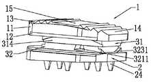
图1是本发明人工颈椎间盘的结构分解示意图。Fig. 1 is a schematic exploded view of the structure of the artificial cervical intervertebral disc of the present invention.
图2是本发明人工颈椎间盘的结构装配示意图。Fig. 2 is a schematic diagram of the structural assembly of the artificial cervical intervertebral disc of the present invention.
图3是本发明人工颈椎间盘的结构剖面视图。Fig. 3 is a cross-sectional view of the structure of the artificial cervical intervertebral disc of the present invention.
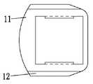
图4是本发明上底板的结构示意图。Fig. 4 is a schematic structural view of the upper base plate of the present invention.
图5是图4的侧视图。FIG. 5 is a side view of FIG. 4 .
图6是图4的剖视图。FIG. 6 is a sectional view of FIG. 4 .
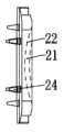
图7是本发明下底板的结构示意图。Fig. 7 is a schematic structural view of the lower base plate of the present invention.
图8是图7的侧视图。FIG. 8 is a side view of FIG. 7 .
图9是图7的剖视图。FIG. 9 is a sectional view of FIG. 7 .
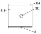
图10是本发明上髓核的结构示意图。Fig. 10 is a schematic diagram of the structure of the upper nucleus pulposus of the present invention.
图11是图10的侧视图。FIG. 11 is a side view of FIG. 10 .
图12是图10的剖视图。FIG. 12 is a sectional view of FIG. 10 .
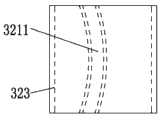
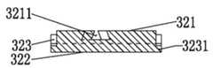
图13是本发明下髓核的结构示意图。Fig. 13 is a schematic structural view of the lower nucleus pulposus of the present invention.
图14是图13的侧视图。FIG. 14 is a side view of FIG. 13 .
图15是图13的剖视图。FIG. 15 is a sectional view of FIG. 13 .
图16是人体坐标轴的示意图。Fig. 16 is a schematic diagram of human body coordinate axes.
主要组件符号说明:Description of main component symbols:
上底板1、板体11、弧形槽12、弧形轨道121、前端弧形锯齿面13、后端弧形锯齿面14、平面15、下底板2、板体21、弧形凹槽22、L形弧形轨道23、卡扣221、倒齿24、髓核3、上髓核31、凸柱311、上弧形凸面312、下平面313、弧形翼缺槽314、下髓核32、上平面321、弧形燕尾槽3211、下弧形面322、缺槽323、弧形翼3231。
具体实施方式Detailed ways
本发明下面将结合附图作进一步详述: The present invention will be described in further detail below in conjunction with accompanying drawing:
请参阅图1、图2、图3、图16所示,所述人工颈椎间盘,包括上底板1、下底板2和设于上底板1与下底板2之间的髓核3,所述髓核由相互扣接在一起的带凸柱311的上髓核31和供所述凸柱311嵌套的弧形燕尾槽3211的下髓核32构成;所述上底板1与所述上髓核31配合,绕冠状轴旋转,模拟颈椎间盘的前屈后伸机能,并允许上底板1和上髓核31发生前后方向的相对微平移;所述上髓核31与所述下髓核31配合,既可绕上髓核31自身凸柱311的旋转轴旋转,又可绕所述下髓核32的弧形燕尾槽3211的旋转轨迹公转,使瞬时可变的垂直轴旋转轴与颈椎间盘的生理状态相符合,限制假体从垂直轴向脱出;所述下髓核32与所述下底板2配合,绕矢状轴旋转,承担左、右侧弯的运动机能,且允许下底板2和下髓核32发生左、右方向的相对微平移;与颈椎间盘的生理特征相符合的人工颈椎间盘的初始前倾角5°;所述上底板1、所述下底板2可与不同高度系列的上髓核31、下髓核32配合,以满足不同人种颈椎间盘的解剖特征。See also Fig. 1, Fig. 2, Fig. 3, shown in Fig. 16, described artificial cervical intervertebral disc, comprises
请参阅图4、图5、图6、图16所示,所述上底板1由板体11、板体下表面凹设旋转轴与冠状轴平行且位于下位椎体(图中未示)的弧形槽12、弧形槽12左、右两端分别凹设供上髓核31的左、右两端设置缺槽314带有的弧形翼配合以限制假体从垂直轴向脱出的弧形轨道121、板体11上表面的前端所设的弧形锯齿面13、板体11上表面的后端所设的弧形锯齿面14、上底板11上表面中间的平面15组成。所述前端弧形锯齿面13的锯齿面锯齿方向朝后,而所述后端弧形锯齿面14的锯齿面锯齿方向朝前,与颈椎上位椎体(图中未示)的下表面配合,在头颈部的重力作用下,上底板1的上表面锯齿面与上位椎体(图中未示)的下表面形成自锁、定位。所述平面15的表面喷涂促骨头长入、固定的钛粉和羟基磷灰石。Please refer to Fig. 4, Fig. 5, Fig. 6, and Fig. 16, the
请参阅图7、图8、图9、图16所示,所述下底板2由板体21、板体上表面凹设旋转轴与矢状轴平行且位于上位椎体(图中未示)的弧形凹槽22、弧形凹槽22的沿轴向的纵边分别凹设弧形轨道23、弧形凹槽22的两端沿径向的横边分别沿轴向凸设与下髓核32的前、后两端设置缺槽所构成的弧形翼配合以限制假体从垂直轴向脱出的卡扣221、板体21下表面凸设若干的倒齿24组成。Please refer to Fig. 7, Fig. 8, Fig. 9, and Fig. 16, the
请参阅图10、图11、图12、图16所示,所述上髓核31由旋转轴与冠状轴平行且位于下位椎体(图中未示)的上弧形凸面312、下平面313、二侧边自下平面313向上弧形面312沿轴向的纵边分别凹设与上底板1的弧形槽12适配的弧形轨道121配合以限制假体从垂直轴向脱出的弧形翼缺槽314、下平面313位于中央部位凸设与颈椎间盘的生理旋转中心重合且与下髓核32弧形燕尾槽3211配合以限制假体从垂直轴向脱出的凸柱311组成;所述上髓核31的前、后两端设置的弧形翼缺槽314与所述上底板弧形槽12前、后两端的弧形轨道121配合以限制假体从垂直轴向脱出。所述上髓核31上弧形凸面312的半径等于或略小于上底板弧形槽12的半径。Please refer to Fig. 10, Fig. 11, Fig. 12, and Fig. 16, the
请参阅图13、图14、图15、图16所示,所述下髓核32由上平面321、旋转轴与矢状轴平行且位于上位椎体(图中未示)的下弧形面322、上平面321中央部位沿径向凹设旋转中心位于脊柱后柱(图中未示)的弧形燕尾槽3211、二端面分别自上平面321向下弧形面322凹设成型有弧形翼3231的缺槽323组成。所述下髓核下弧形面322的半径等于或略小于下底板弧形凹槽22的半径。上髓核31下表面的凸柱311与下髓核32上表面的弧形燕尾槽3211配合,限制假体从垂直轴向脱出。Please refer to Fig. 13, Fig. 14, Fig. 15, and Fig. 16, the
工作原理:本发明采用上述四个构件,即上底板1,上髓核31,下髓核32,下底板2,通过三个关节面连结成为一个相对稳定的颈椎间盘假体,其中上底板1与上髓核31所形成的关节面的旋转轴与冠状轴平行且位于下位椎体,上髓核31与下髓核32所形成的关节面的旋转轴与垂直轴平行且位于脊柱后柱,下底板2与下髓核32所形成的关节面的旋转轴与矢状轴平行且位于上位椎体,使得该人工颈椎间盘在颈椎屈伸、侧弯、旋转状态下都能提供符合自然生理状态的瞬时旋转中心,最大限度恢复了人体颈椎的自然生理状态。Working principle: The present invention adopts the above four components, namely the
以上所述仅为本发明的较佳实施例,凡依本发明权利要求范围所做的均等变化与修饰,皆应属本发明权利要求的涵盖范围。The above descriptions are only preferred embodiments of the present invention, and all equivalent changes and modifications made according to the scope of the claims of the present invention shall fall within the scope of the claims of the present invention.
Claims (10)
Priority Applications (1)
| Application Number | Priority Date | Filing Date | Title |
|---|---|---|---|
| CN201210217748.8ACN102727329B (en) | 2012-06-28 | 2012-06-28 | Artificial cervical intervertebral disc |
Applications Claiming Priority (1)
| Application Number | Priority Date | Filing Date | Title |
|---|---|---|---|
| CN201210217748.8ACN102727329B (en) | 2012-06-28 | 2012-06-28 | Artificial cervical intervertebral disc |
Publications (2)
| Publication Number | Publication Date |
|---|---|
| CN102727329Atrue CN102727329A (en) | 2012-10-17 |
| CN102727329B CN102727329B (en) | 2015-01-07 |
Family
ID=46984113
Family Applications (1)
| Application Number | Title | Priority Date | Filing Date |
|---|---|---|---|
| CN201210217748.8AExpired - Fee RelatedCN102727329B (en) | 2012-06-28 | 2012-06-28 | Artificial cervical intervertebral disc |
Country Status (1)
| Country | Link |
|---|---|
| CN (1) | CN102727329B (en) |
Cited By (4)
| Publication number | Priority date | Publication date | Assignee | Title |
|---|---|---|---|---|
| CN105213073A (en)* | 2015-10-21 | 2016-01-06 | 重庆医科大学附属第二医院 | rear artificial atlanto-tooth joint |
| CN112085833A (en)* | 2020-08-24 | 2020-12-15 | 南昌大学第一附属医院 | A method for analyzing three-dimensional motion of cervical vertebrae in vivo by combining cone beam CT and image fusion |
| CN113143548A (en)* | 2021-03-22 | 2021-07-23 | 上海交通大学医学院附属第九人民医院 | Artificial intervertebral disc tissue, construction method, preparation method, computer-readable storage medium and equipment |
| CN114145888A (en)* | 2021-12-28 | 2022-03-08 | 北京理贝尔生物工程研究所有限公司 | Atlantoaxial joint prosthesis |
Citations (9)
| Publication number | Priority date | Publication date | Assignee | Title |
|---|---|---|---|---|
| US6517580B1 (en)* | 2000-03-03 | 2003-02-11 | Scient'x Societe A Responsabilite Limited | Disk prosthesis for cervical vertebrae |
| WO2004002291A2 (en)* | 2002-06-26 | 2004-01-08 | Nuvasive, Inc. | Total disc replacement system and related methods |
| CN1697633A (en)* | 2002-03-30 | 2005-11-16 | 无限整形外科有限公司 | Intervertebral Devices and Methods of Use |
| CN1720873A (en)* | 2001-05-04 | 2006-01-18 | Ldr医学公司 | Intervertebral disc prosthesis and fitting tools |
| WO2006042870A1 (en)* | 2004-09-08 | 2006-04-27 | Cesar Sebastian Bueno | Universal intervertebral disc prosthesis |
| CN1816309A (en)* | 2003-05-30 | 2006-08-09 | Sdgi控股股份有限公司 | Implants based on engineered metal matrix composite materials having enhanced imaging and wear resistance |
| CN101022770A (en)* | 2004-06-30 | 2007-08-22 | 辛纳吉椎间盘置换公司 | Artificial spinal disc |
| CN101961270A (en)* | 2004-02-04 | 2011-02-02 | Ldr医学公司 | Intervertebral disk prosthesis |
| CN102232880A (en)* | 2010-04-23 | 2011-11-09 | 蒋秀英 | Artificial intervertebral disk |
- 2012
- 2012-06-28CNCN201210217748.8Apatent/CN102727329B/ennot_activeExpired - Fee Related
Patent Citations (9)
| Publication number | Priority date | Publication date | Assignee | Title |
|---|---|---|---|---|
| US6517580B1 (en)* | 2000-03-03 | 2003-02-11 | Scient'x Societe A Responsabilite Limited | Disk prosthesis for cervical vertebrae |
| CN1720873A (en)* | 2001-05-04 | 2006-01-18 | Ldr医学公司 | Intervertebral disc prosthesis and fitting tools |
| CN1697633A (en)* | 2002-03-30 | 2005-11-16 | 无限整形外科有限公司 | Intervertebral Devices and Methods of Use |
| WO2004002291A2 (en)* | 2002-06-26 | 2004-01-08 | Nuvasive, Inc. | Total disc replacement system and related methods |
| CN1816309A (en)* | 2003-05-30 | 2006-08-09 | Sdgi控股股份有限公司 | Implants based on engineered metal matrix composite materials having enhanced imaging and wear resistance |
| CN101961270A (en)* | 2004-02-04 | 2011-02-02 | Ldr医学公司 | Intervertebral disk prosthesis |
| CN101022770A (en)* | 2004-06-30 | 2007-08-22 | 辛纳吉椎间盘置换公司 | Artificial spinal disc |
| WO2006042870A1 (en)* | 2004-09-08 | 2006-04-27 | Cesar Sebastian Bueno | Universal intervertebral disc prosthesis |
| CN102232880A (en)* | 2010-04-23 | 2011-11-09 | 蒋秀英 | Artificial intervertebral disk |
Cited By (4)
| Publication number | Priority date | Publication date | Assignee | Title |
|---|---|---|---|---|
| CN105213073A (en)* | 2015-10-21 | 2016-01-06 | 重庆医科大学附属第二医院 | rear artificial atlanto-tooth joint |
| CN112085833A (en)* | 2020-08-24 | 2020-12-15 | 南昌大学第一附属医院 | A method for analyzing three-dimensional motion of cervical vertebrae in vivo by combining cone beam CT and image fusion |
| CN113143548A (en)* | 2021-03-22 | 2021-07-23 | 上海交通大学医学院附属第九人民医院 | Artificial intervertebral disc tissue, construction method, preparation method, computer-readable storage medium and equipment |
| CN114145888A (en)* | 2021-12-28 | 2022-03-08 | 北京理贝尔生物工程研究所有限公司 | Atlantoaxial joint prosthesis |
Also Published As
| Publication number | Publication date |
|---|---|
| CN102727329B (en) | 2015-01-07 |
Similar Documents
| Publication | Publication Date | Title |
|---|---|---|
| CN101022770B (en) | artificial spinal disc | |
| US8403989B2 (en) | Physologically movable intervertebral disc prosthesis for the lumbar and cervical spine | |
| CA2497278C (en) | Intervertebral implant comprising a three-part articulation | |
| CN101068512B (en) | Interdiscal prosthesis for lumbar and cervical spine with transverse arcuate curved cylindrical articulation surfaces | |
| US9308100B2 (en) | Intervertebral disc prosthesis with a motion-adapted edge for the lumbar and cervical spine | |
| CN204839838U (en) | Artifical neck intervertebral disc false body | |
| ES2331007T3 (en) | UNIVERSAL APPLICATION INTERVERTEBRAL DISK PROTESIS. | |
| CN105105889B (en) | A kind of artificial lumbar disc prostheses | |
| CN101980671A (en) | Joint prostheses | |
| CN102727329B (en) | Artificial cervical intervertebral disc | |
| CN103417313A (en) | Artificial intervertebral disc prosthesis | |
| CN101087572A (en) | Modular intervertebral implant | |
| CN103565561B (en) | Artificial lumbar intervertebral disc | |
| CN107374790A (en) | A kind of porous soleplate formula cervical artificial disc prosthese | |
| CN202027749U (en) | Integral artificial intervertebral disc | |
| CN103228233B (en) | Prosthesis for cervical and lumbar vertebrae | |
| JP6629833B2 (en) | Disc implant | |
| CN2244386Y (en) | Hip femoral prosthetic implant and acetabular prosthetic implant used in conjunction with it | |
| CN109157312B (en) | A lumbar intervertebral disc prosthesis structure based on metal rubber and its working method | |
| CN206434448U (en) | Artificial cervical intervertebral disk prosthesis | |
| US9795491B2 (en) | Intervertebral disc prosthesis and intervertebral prosthetic unit | |
| CN103300948A (en) | Omega-shaped artificial cervical intervertebral disc implant with diamond-shaped bilateral stopping pawls | |
| CN204072392U (en) | intervertebral device | |
| CN210144807U (en) | Artificial cervical disc prosthesis | |
| CN103315830A (en) | Omega-shaped artificial cervical disc implantation prosthesis with inverted-V-shaped two-way stopping inverted teeth |
Legal Events
| Date | Code | Title | Description |
|---|---|---|---|
| C06 | Publication | ||
| PB01 | Publication | ||
| C10 | Entry into substantive examination | ||
| SE01 | Entry into force of request for substantive examination | ||
| C14 | Grant of patent or utility model | ||
| GR01 | Patent grant | ||
| CF01 | Termination of patent right due to non-payment of annual fee | Granted publication date:20150107 Termination date:20210628 | |
| CF01 | Termination of patent right due to non-payment of annual fee |