CN102727163A - Endoscope and imaging device thereof - Google Patents
Endoscope and imaging device thereofDownload PDFInfo
- Publication number
- CN102727163A CN102727163ACN2012100466905ACN201210046690ACN102727163ACN 102727163 ACN102727163 ACN 102727163ACN 2012100466905 ACN2012100466905 ACN 2012100466905ACN 201210046690 ACN201210046690 ACN 201210046690ACN 102727163 ACN102727163 ACN 102727163A
- Authority
- CN
- China
- Prior art keywords
- signal cable
- endoscope
- imaging device
- supply pipe
- cable
- Prior art date
- Legal status (The legal status is an assumption and is not a legal conclusion. Google has not performed a legal analysis and makes no representation as to the accuracy of the status listed.)
- Granted
Links
Images


Landscapes
- Endoscopes (AREA)
- Instruments For Viewing The Inside Of Hollow Bodies (AREA)
Abstract
Description
Translated fromChinese技术领域technical field
本发明涉及内窥镜及其摄像装置。The invention relates to an endoscope and an imaging device thereof.
背景技术Background technique
内窥镜具有插入被检体例如患者的体内的插入部和用于对该插入部进行操作的操作部。该插入部从前端按顺序划分为前端硬质部、弯曲部、挠性部。在前端硬质部的前表面设置有观察窗、照明窗、钳子出口、送气/送水喷嘴。在观察窗的背面配置有摄像装置,且在照明窗的背面配置有光导(ライトガイド)。弯曲部设为连结有多个关节环的构造,通过线式操作能够使前端硬质部朝向所期望的方向。挠性部为了使前端硬质部可到达所期望的观察部位,设为1m~2m程度的长度。An endoscope has an insertion portion inserted into a body of a subject such as a patient, and an operation portion for operating the insertion portion. The insertion part is divided into a front end rigid part, a curved part, and a flexible part in order from the front end. An observation window, an illumination window, a pliers outlet, and an air/water supply nozzle are arranged on the front surface of the front end hard part. An imaging device is arranged on the back of the observation window, and a light guide is arranged on the back of the illumination window. The bending part has a structure in which a plurality of joint rings are connected, and the distal hard part can be directed in a desired direction by a wire operation. The length of the flexible part is about 1 m to 2 m so that the distal hard part can reach a desired observation site.
摄像装置具有由多个光学零件、例如透镜及棱镜等构成的光学系统、和将通过该光学系统成像的光学图像光电转换为摄像信号的CCD等固体摄像元件。固体摄像元件安装于电路基板上,或与电路基板连接。在该电路基板的连接部连接有信号电缆。另外,在电路基板上安装有用于驱动固体摄像元件的电子零件。来自摄像装置的摄像信号经由电路基板、信号电缆被送入与内窥镜连接的处理器装置。在该处理器装置对摄像信号进行图像处理,在监视器上显示观察部位的图像。The imaging device has an optical system composed of a plurality of optical components such as lenses and prisms, and a solid-state imaging element such as a CCD that photoelectrically converts an optical image formed by the optical system into an imaging signal. The solid-state imaging element is mounted on or connected to a circuit board. A signal cable is connected to the connection portion of the circuit board. In addition, electronic components for driving the solid-state imaging element are mounted on the circuit board. An imaging signal from the imaging device is sent to a processor device connected to the endoscope via a circuit board and a signal cable. Image processing is performed on the imaging signal by the processor device, and an image of the observed site is displayed on the monitor.
作为将来自摄像装置的信号送入图像处理装置的信号电缆,可使用例如复合多芯电缆。该信号电缆由于遍及插入部的全长插通,所以每当插入部被缠绕或被弯曲时,都被强烈地推拉。因此,存在被焊接的信号电缆从电路基板的连接部剥离的情况。As a signal cable for sending a signal from the imaging device to the image processing device, for example, a composite multi-core cable can be used. Since the signal cable is inserted over the entire length of the insertion portion, it is strongly pushed and pulled whenever the insertion portion is twisted or bent. Therefore, the soldered signal cable may be detached from the connection portion of the circuit board.
为了防止该信号电缆剥离而提出了各种提案。例如,在特开平5-261064号公报记载的内窥镜中,在柔性电路基板的一端侧焊接有信号电缆,同时,以包围该被焊接的信号电缆的方式将柔性电路基板折弯成U字形。而且,该折弯的部分的周围被密封带和绝缘带被覆,向折弯部分的空间充填环氧系粘接剂并固定为使其不变形。而且,柔性电路基板经由按压板通过固定螺钉与连结筒固定。由此,即使信号电缆被强烈地推拉,柔性电路基板也不会移动。另外,由于由信号电缆对柔性电路基板施加的扭曲及倾斜的力也在柔性电路基板被吸收,因此,扭曲等力不会传递给固体摄像元件及光学系统。Various proposals have been made to prevent the signal cable from being peeled off. For example, in the endoscope described in JP-A-5-261064, a signal cable is welded to one end side of a flexible circuit board, and at the same time, the flexible circuit board is bent into a U-shape so as to surround the welded signal cable. . Then, the periphery of the bent portion is covered with a sealing tape and an insulating tape, and an epoxy-based adhesive is filled into the space of the bent portion and fixed so as not to deform. Furthermore, the flexible circuit board is fixed to the connecting cylinder by fixing screws via the pressing plate. Thereby, even if the signal cable is strongly pushed and pulled, the flexible circuit board does not move. In addition, since the force of twisting and tilting applied to the flexible circuit board by the signal cable is also absorbed by the flexible circuit board, the force such as twisting is not transmitted to the solid-state imaging device and the optical system.
在特开平9-146011号公报记载的摄像装置中,柔性电路基板和信号电缆的连接部由密封材料覆盖固定。In the imaging device disclosed in JP-A-9-146011, the connecting portion between the flexible circuit board and the signal cable is covered and fixed with a sealing material.
特开2008-118568号公报记载的摄像装置具备固体摄像元件及收容柔性电路基板的电子零件的加强框,在该加强框的内侧充填有粘接剂。而且,用热收缩套管包覆焊接于柔性电路基板上的信号电缆的前端部分和加强框,向该内侧充填粘接剂进行密封。The imaging device described in JP-A-2008-118568 includes a solid-state imaging element and a reinforcement frame for housing electronic components of a flexible circuit board, and an adhesive is filled inside the reinforcement frame. Then, the front end portion of the signal cable soldered to the flexible circuit board and the reinforcement frame are covered with a heat-shrinkable sleeve, and the inner side is filled with an adhesive for sealing.
在特开平5-261064号公报记载的摄像装置中,需要进行将电路基板通过固定螺钉与连结筒固定的复杂的作业。在特开平9-146011号公报记载的摄像装置中,推拉信号电缆的力会传递给柔性电路基板的连接部及柔性电路基板。由此,对柔性电路基板的连接部、及柔性电路基板和固体摄像元件的连接部等作用力,其中,在弱的部位有可能产生剥离或破损。In the imaging device described in JP-A-5-261064, a complicated work of fixing the circuit board to the connecting cylinder with fixing screws is required. In the imaging device described in JP-A-9-146011, the force of pushing and pulling the signal cable is transmitted to the connection portion of the flexible circuit board and the flexible circuit board. As a result, force acts on the connection portion of the flexible circuit board, the connection portion of the flexible circuit board and the solid-state imaging device, etc., and among them, peeling or damage may occur at weak points.
在特开2008-118568号记载的摄像装置中,在将固体摄像元件收容于加强框的内部的关系方面,加强框的尺寸受到固体摄像元件的尺寸的制约。对于内窥镜要求高画质化、细径化、热压应对(オ一トクレ一ブ)等,随之,固体摄像元件及其周边的零件也变得多样化且复杂化。若伴随在固体摄像元件及其周边零件执行的功能增加,电子零件的安装空间变得大型化,则收容它们的加强框也大型化。由此,前端硬质部的直径变粗,会增加患者的负担。In the imaging device described in Japanese Unexamined Patent Publication No. 2008-118568, the size of the reinforcement frame is restricted by the size of the solid-state imaging device in relation to housing the solid-state imaging device inside the reinforcement frame. Higher image quality, smaller diameter, autoclave, etc. are required for endoscopes, and accordingly, solid-state imaging devices and their peripheral parts have become diverse and complicated. As the functions performed by the solid-state imaging device and its peripheral components increase, the mounting space for electronic components increases, and the reinforcement frame for accommodating them also increases in size. As a result, the diameter of the distal hard portion becomes thicker, which increases the burden on the patient.
上述的任何一种摄像装置,由于没有限制前端硬质部内的信号电缆的位置,因此,若使插入部弯曲、或者在内窥镜的使用中对弯曲部弯曲操作,则有可能在插入部的前端侧(前端硬质部及弯曲部内)产生管或光导等内置物的排列错乱及与内置物的干涉。该内置物的排列错乱及与内置物的干涉导致产生信号电缆的断裂及接合部的剥离,从而使耐久性降低。Any of the above-mentioned imaging devices does not limit the position of the signal cable in the hard part of the front end. Therefore, if the insertion part is bent, or the bending part is bent during the use of the endoscope, it is possible that the position of the insertion part will be damaged. On the front end side (in the front hard part and the curved part), the arrangement of the built-in components such as tubes and light guides is disordered and interference with the built-in components occurs. Disarrangement of the arrangement of the built-in parts and interference with the built-in parts lead to breakage of the signal cable and detachment of the joint portion, resulting in reduced durability.
发明内容Contents of the invention
本发明的目的在于提供一种内窥镜及其摄像装置,其能够抑制在插入部的前端侧内置物的排列错乱及与内置物的干涉,且能够抑制信号电缆的断裂及在电路基板的连接部的剥离。The object of the present invention is to provide an endoscope and an imaging device thereof, which can suppress the disorder of the built-in objects on the front end side of the insertion part and the interference with the built-in objects, and can suppress the breakage of the signal cable and the connection to the circuit board. Partial stripping.
本发明的另一目的在于提供一种内窥镜及其摄像装置,其通过使前端硬质部的直径变细,可减轻患者的负担。Another object of the present invention is to provide an endoscope and an imaging device thereof, which can reduce the burden on the patient by reducing the diameter of the distal end hard portion.
为了实现上述目的,本发明提供一种内窥镜用摄像装置,其具备:收纳有摄像透镜的透镜镜筒、对通过摄像透镜成像的光学图像进行光电转换的固体摄像元件、安装有固体摄像元件的电路基板、信号电缆、偏移部件。信号电缆具有多根原线及被覆其的外皮,各原线与电路基板电连接。偏移部件使摄像透镜的光轴与信号电缆的中心轴成为偏移状态。In order to achieve the above object, the present invention provides an imaging device for an endoscope, which includes: a lens barrel accommodating an imaging lens; a solid-state imaging element for photoelectrically converting an optical image formed by the imaging lens; circuit boards, signal cables, offset components. The signal cable has a plurality of primary wires and a sheath covering them, and each primary wire is electrically connected to the circuit board. The offset member offsets the optical axis of the imaging lens and the central axis of the signal cable.
优选设置保持透镜镜筒的保持部件。作为偏移部件,使用底板部的两端连设侧板部且以横截面为U字形的方式在上部形成有开口部的加强框。该加强框的一端固定于保持部件,另一端固定于信号电缆的外皮。优选从开口部注入粘接剂,通过向加强框内充填的粘接剂使电缆原线一体化。Preferably, a holding member for holding the lens barrel is provided. As the offset member, a reinforcing frame is used in which side plate portions are connected to both ends of the bottom plate portion and an opening portion is formed in the upper portion so that the cross section is U-shaped. One end of the reinforcing frame is fixed to the holding member, and the other end is fixed to the sheath of the signal cable. Preferably, the adhesive is injected from the opening, and the original cable wires are integrated with the adhesive filled into the reinforcing frame.
加强框具有横截面的截面面积随着朝向后方边向一侧靠拢边逐渐地减小的缩颈部、和在该缩颈部的后端收容有信号电缆的外皮的电缆固定部。该缩颈部使摄像透镜的光轴和信号电缆的中心轴成为偏移状态。The reinforcement frame has a constricted portion whose cross-sectional area gradually decreases toward one side as it moves toward the rear, and a cable fixing portion that accommodates a sheath of the signal cable at a rear end of the constricted portion. The constricted portion makes the optical axis of the imaging lens and the central axis of the signal cable shifted.
本发明提供一种内窥镜,其具有插入体腔内的插入部、存在于该插入部的前端侧的前端硬质部、安装于前端硬质部内的透镜镜筒及固体摄像元件、安装有固体摄像元件的电路基板、插通到插入部内的信号电缆、偏移部件。透镜镜筒收纳有摄像透镜。固体摄像元件对通过摄像透镜成像的光学图像进行光电转换。信号电缆具有多根原线及被覆其的外皮,这些各原线与电路基板电连接。偏移部件使摄像透镜的光轴和信号电缆的中心轴成为偏移状态。The present invention provides an endoscope, which has an insertion part inserted into a body cavity, a front end hard part present on the front end side of the insertion part, a lens barrel and a solid-state imaging element installed in the front end hard part, and a solid-state The circuit board of the imaging element, the signal cable inserted into the insertion part, and the deflection member. The lens barrel accommodates an imaging lens. A solid-state imaging element performs photoelectric conversion of an optical image formed by an imaging lens. The signal cable has a plurality of primary wires and a sheath covering them, and each of these primary wires is electrically connected to the circuit board. The offset member offsets the optical axis of the imaging lens and the central axis of the signal cable.
优选在插入部插通有光导、钳子通道、送气管及送水管。在前端硬质部的前表面设置有:配置于光导的前方的照明窗、与钳子通道连通的钳子出口、配置于透镜镜筒的前表面的观察窗、与送气管及送水管连通的送气/送水喷嘴。Preferably, a light guide, a forceps channel, an air supply tube and a water supply tube are inserted through the insertion part. The front surface of the front end hard part is provided with: an illumination window arranged in front of the light guide, a pliers outlet communicated with the pliers channel, an observation window arranged on the front surface of the lens barrel, and an air supply/supply pipe communicated with the air supply pipe and the water supply pipe. Water delivery nozzle.
优选偏移部件相对于前端硬质部的中心轴将信号电缆定位于钳子通道的对角位置。Preferably, the offset member positions the signal cable at a diagonal position of the forceps channel with respect to the central axis of the front hard part.
优选插入部紧接着前端硬质部具有弯曲部,该弯曲部通过连接销可上下左右弯曲地连结有多个关节环。It is preferable that the insertion part has a bent part next to the distal end hard part, and the bent part connects a plurality of joint rings so as to be bendable up, down, left, and right via connecting pins.
优选弯曲部的横截面相对于关节环的中心轴通过连接点对称的一对连接销的假想线以90°间隔被划分为第一~第四区域。优选在第一区域配置钳子通道,在第二区域配置第一光导,在第三区域配置信号电缆及第二光导,在第四区域配置送气管/送水管。Preferably, the cross-section of the bent portion is divided into first to fourth regions at intervals of 90° through an imaginary line of a pair of connecting pins symmetrical to the connecting point with respect to the central axis of the joint ring. Preferably, the channel for forceps is arranged in the first area, the first light guide is arranged in the second area, the signal cable and the second light guide are arranged in the third area, and the air supply pipe/water supply pipe is arranged in the fourth area.
另外,也可以使钳子通道位于第一区间,使第一光导位于第二区域,使信号电缆及送气管/送水管位于第三区域,使第二光导位于第四区域。In addition, the channel of the forceps can also be located in the first section, the first light guide can be located in the second area, the signal cable and air supply pipe/water supply pipe can be located in the third area, and the second light guide can be located in the fourth area.
根据本发明,由于通过偏移部件使信号电缆的中心轴相对于摄像透镜的光轴成为偏移状态,因此,在插入部的前端侧,信号电缆能够配置于不干涉其它内置物的位置。另外,除了不存在与其它部件的干涉之外,还能够抑制各内置物从规定的排列区域移动的排列错乱。因此,防止由其它部件的干涉及排列错乱引起的信号电缆的断裂及信号电缆的连接部的剥离,从而它们的耐久性提高。According to the present invention, since the central axis of the signal cable is offset from the optical axis of the imaging lens by the offset member, the signal cable can be arranged at a position where it does not interfere with other built-in items on the front end side of the insertion portion. In addition, in addition to the absence of interference with other components, it is also possible to suppress the disorder of the arrangement in which the built-in objects move from the predetermined arrangement region. Therefore, breakage of the signal cable and peeling of the connection portion of the signal cable due to interference of other components and misalignment are prevented, thereby improving their durability.
通过使用偏移部件使信号电缆相对于前端硬质部的中心轴定位于钳子通道的对角位置,从而即使弯曲部弯曲也能够起到偏移部件的偏移保持效果,从而抑制钳子通道与信号电缆的位置关系的失调。因此,能够减轻弯曲带来的信号电缆的压力,能够实现防止信号电缆的断裂及耐久性的提高。另外,通过基于偏移部件的各管的慢弯位置限制效果,成为在插入部的前端侧的各区域内对各管类的间隙进行确保的平衡性良好的配置。由此,也能够抑制由平衡不良引起的弯曲动作时的各管类的滑动阻抗的增加。By using the offset member to position the signal cable at the diagonal position of the forceps channel with respect to the central axis of the hard part at the front end, even if the bending part bends, the offset holding effect of the offset member can be achieved, thereby suppressing the forceps channel and the signal Misadjustment of the positional relationship of the cables. Therefore, the pressure of the signal cable due to bending can be reduced, and the breakage prevention and durability improvement of the signal cable can be realized. In addition, due to the slow-bending position restriction effect of each tube by the offset member, it becomes a well-balanced arrangement that ensures a gap between the tubes in each region on the front end side of the insertion portion. Thereby, it is also possible to suppress an increase in the sliding resistance of each tube during a bending operation due to poor balance.
附图说明Description of drawings
图1是表示本发明的电子内窥镜系统的立体图。FIG. 1 is a perspective view showing an electronic endoscope system of the present invention.
图2是表示插入部的前端侧的剖面图。Fig. 2 is a sectional view showing the front end side of the insertion part.
图3是表示插入部的前表面的主视图。Fig. 3 is a front view showing the front surface of the insertion part.
图4是表示摄像装置的外观的立体图。FIG. 4 is a perspective view showing the appearance of the imaging device.
图5是摄像装置的侧视图。Fig. 5 is a side view of the imaging device.
图6是摄像装置的主视图。Fig. 6 is a front view of the imaging device.
图7是表示加强框与信号电缆的固定的侧视图,使其局部成剖面。Fig. 7 is a side view showing the fixing of the reinforcing frame and the signal cable, partially in section.
图8是加强框的立体图。Fig. 8 is a perspective view of a reinforcing frame.
图9是表示弯曲部的内置物的配置一个例子的剖面图。Fig. 9 is a cross-sectional view showing an example of the arrangement of built-in parts of the bending portion.
图10是表示另一实施方式的前表面的主视图。Fig. 10 is a front view showing a front surface of another embodiment.
图11是表示弯曲部的内置物的配置另一个例子的剖面图。Fig. 11 is a cross-sectional view showing another example of the arrangement of built-in parts of the bending portion.
图12表示信号电缆的固定部的位置,(A)表示固定部存在于前端硬质部内的例子,(B)表示存在于弯曲部内的例子。12 shows the position of the fixing part of the signal cable, (A) shows an example where the fixing part exists in the front end rigid part, and (B) shows an example where the fixing part exists in the bent part.
具体实施方式Detailed ways
图1中,电子内窥镜系统10具备电子内窥镜11、处理器装置12、和光源装置13。电子内窥镜11具有:插入被检体(例如患者)的内部的挠性插入部14、连设于插入部14的基端部分的操作部15、与处理器装置12及光源装置13连接的连接器16。通用线缆(ユニバ一サルコ一ド:universal cord)17连接操作部15和连接器16。In FIG. 1 , an
在操作部15的前端侧设置有钳子口18。在钳子口18插通电刀(電気メス)等处理工具(処置具)。钳子口18通过插入部14内的钳子通道19(参照图2),并与前端面14a的钳子出口20(参照图2及图3)连通。A
操作部15具备角型旋钮21、送气/送水按钮22、吸引按钮23、释放按钮(レリ一ズボタン)等各种操作部件。角型旋钮21通过旋转操作使插入部14的前端硬质部31在上下左右方向弯曲。送气/送水按钮22通过按压操作使空气或水从送气/送水喷嘴43(参照图3)喷出。吸引按钮23通过按压操作从钳子出口20吸引体内的液体或组织等被吸引物。释放按钮被按压时,将显示中的观察图像作为静止图像记录于监视器27上。The
处理器装置12与光源装置13电连接,统一控制电子内窥镜系统10的动作。处理器装置12经由通用线缆17、插通于插入部14内的信号电缆(cable)25(参照图2)对电子内窥镜11进行供电,并对搭载于前端硬质部31的摄像装置26(参照图2)的驱动进行控制。进而,处理器装置12经由信号电缆25接收来自摄像装置26的摄像信号,实施各种处理并生成图像数据。在处理器装置12上连接有监视器27。监视器27基于来自处理器装置12的图像数据显示观察图像。The
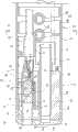
插入部14从前表面14a按顺序划分为前端硬质部31、弯曲部32、及挠性部33。如图2所示,前端硬质部31在硬质树脂制的前端部主体35上被覆有软质树脂制的前端盖30。该前端部主体35和与该前端部主体35相接的弯曲部32的金属制前端筒37,用软质树脂制的管36被覆。The
弯曲部32由前端筒37、和通过连接销39将多个关节环38a、38b、38c、…连接而成的关节环单元38构成,通过销结合部分在规定角度内旋转而进行弯曲(参照图12)。在弯曲部32内,从操作部15的角型旋钮21插通有四根电线34(参照图9),这些电线34通过角型旋钮21的旋转操作被推拉。通过该推拉,弯曲部32向上下左右方向以任意角度弯曲。由此,前端硬质部31朝向体腔内的所期望的方向,能够通过摄像装置26对体腔内的观察部位进行摄像。挠性部33为连接操作部15与弯曲部32之间的部分。挠性部33为在细长的钢板的螺旋物上卷绕网,并在其上被覆软质树脂制的管36而成。The bending
前端部主体35由硬质树脂制的圆柱体构成,朝向后端在外周面按顺序形成有第一台阶部(段部)35a、第二台阶部35b。在第二台阶部35b接合有弯曲部32的前端筒37。另外,在第一台阶部35a接合有软质树脂制的管36。该管36覆盖弯曲部32及挠性部33,构成插入部14的外周表皮。The front end main body 35 is made of a hard resin cylinder, and a first stepped portion (stage portion) 35 a and a second stepped
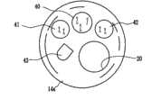
如图3所示,在前表面14a上除设置有钳子出口20之外,还设置有观察窗40,照明窗41、42,以及送气/送水喷嘴43。另外,根据需要,还可以设置喷水口或其它喷嘴等。如图2所示,以与钳子出口20连续的方式在前端部主体35安装有出口筒44,在该后端部的外侧嵌有钳子通道19。另外,在观察窗40的内部形成有摄像装置安装孔45,经由该安装孔45安装摄像装置26。As shown in FIG. 3 , in addition to the
如图2、图4、及图5所示,摄像装置26由镜筒52、棱镜53、棱镜保持部件54、玻璃盖(カバ一グラス)55、CCD56、主电路基板57、子电路基板58、加强框59、密封树脂60、信号电缆25、信号电缆固定部61构成。镜筒52收纳有摄像透镜51。该镜筒52和棱镜53通过棱镜保持部件54被一体保持。As shown in Fig. 2, Fig. 4, and Fig. 5, the
在棱镜53上隔着玻璃盖55固装有CCD56。CCD56安装于主电路基板57上。该CCD56经由棱镜53对通过摄像透镜51成像的光学图像进行光电转换。主电路基板57和子电路基板58经由连接线(未图示)连接,不能安装于主电路基板57的零件等安装于子电路基板58。子电路基板58没有固定于棱镜保持部件54。但是,也可以根据必要,通过定位焊或通过棱镜保持部件54夹持其侧缘部,由此将子电路基板58固定于棱镜保持部件54上。另外,如后面的说明,子电路基板58通过向加强框59内充填密封树脂60,而通过该密封树脂60固定于加强框59内。A
如图7所示,作为信号电缆25使用多芯电缆。该信号电缆25由多根原线(素線)65、捆扎多根原线65的屏蔽线(未图示)、包覆屏蔽线的外皮66构成。而且,多根原线65和屏蔽线焊接于主电路基板57及子电路基板58。另外,信号电缆25的各原线65与子电路基板58及主电路基板57分别连接,代替于此,也可以直接与其中一方连接。As shown in FIG. 7 , a multi-core cable is used as the
如图8所示,加强框59由底板部59a和连设于该两端的侧板部59b、59c构成,横截面形成为U字或通道形,在上部形成有开口部59d。该加强框59被划分为收纳棱镜53及子电路基板58的加强框主体70、接下来的缩颈(絞り)部71、以及信号电缆安装部72。而且,在一端侧的加强框主体70固装有棱镜保持部件54,并在另一端侧的信号电缆安装部72固装有信号电缆25的外皮25a。As shown in FIG. 8 , the
加强框主体70设为棱镜53及子电路基板58可收纳的横截面积,信号电缆安装部72设为可收纳信号电缆25的外皮25a的横截面积。因此,缩颈部71按照随着朝向信号电缆安装部72而横截面积向一侧靠拢并逐渐减小的方式紧缩。另外,如图6所示,通过该缩颈,摄像透镜51的光轴CL1和信号电缆25的中心轴CL2成为偏移状态。X轴方向(水平线方向)的偏移量为OFx,Y轴方向(垂直方向)的偏移量为OFy。信号电缆25的位置相对于摄像装置安装孔45(参照图2)错开这两个偏移量OFx、OFy的量。The reinforcement frame
X轴方向的偏移量OFx、Y轴方向的偏移量OFy可通过改变加强框59的缩颈部71的形状适当更换。由此,能够使信号电缆25相对于光轴CL1向含有XY轴的面内的任意位置错开配置。The offset amount OFx in the X-axis direction and the offset amount OFy in the Y-axis direction can be appropriately changed by changing the shape of the
如图8所示,底板部59a朝向后方延伸设置,形成有比侧板部59b、59c向更后方突出的接合片75。在该接合片75的后端两侧缘形成有卡止爪76。As shown in FIG. 8 , the
图7所示,接合片75形成在与信号电缆25的外周下表面接触的状态下缠绕捆扎线78a,使接合片75及信号电缆25一体化的绕组(糸巻)78。另外,在形成绕组78之前,按照覆盖原线65及屏蔽线的方式使外皮66被覆热收缩被覆管77,以使信号电缆25的屏蔽线不与加强框59接触。而且,绕组78利用粘接剂79固接(固着)。在被覆管77和外皮66之间也涂布有粘接剂79并将它们一体化。通过这些绕组78及粘接剂79构成电缆固定部61。通过该电缆固定部61提高信号电缆25和加强框59的结合强度。As shown in FIG. 7 , the
由于卡止爪76的前端面76a卡止于绕组78的后端,因此,通过弯曲部32的弯曲操作推拉信号电缆25,即使该推拉的力对该电缆固定部61起作用,由于通过卡止爪76、绕组78、粘接剂79提高结合强度,因此,信号电缆25也不会偏离加强框59,能够抑制原线65的焊接连接部的剥离、破损等的产生。Since the
另外,按照覆盖将信号电缆25卷绕于接合片75上的绕组78和涂布于其上的粘接剂79的方式,被覆挠性的保护管80。通过用该保护管80被覆电缆固定部61,在通过弯曲部32的弯曲操作而被折弯时,弯曲力不仅分散于信号电缆25,而且还分散给保护管80,因此,能够实现对信号电缆25的保护。In addition, a flexible
如图4及图6所示,在棱镜保持框架54固定于加强框59时,在棱镜53的三面被底板部59a及侧板部59b、59c覆盖的状态下,棱镜53、子电路基板58被收容于加强框59内。另外,在一方侧板部59b上形成有棱镜保持部件54的侧板部54a的前侧深入的卡止开口85。该卡止开口85延伸至比侧板部54a更后方的位置,在它们之间形成有用于排出剩余粘接剂的间隙85a。As shown in FIGS. 4 and 6, when the
具有CCD56的主电路基板57按照覆盖开口部59d(参照图8)的方式配置于加强框59的外侧。这样,由于将主电路基板57配置于加强框59的外侧,因此,即使在更换为减小像素尺寸而高密度化的CCD的情况下,仅变更主电路基板,根据需要变更子电路基板,就能够轻松应对解像度的规格变更。而且,其它的镜筒52、棱镜53、棱镜保持部件54、加强框59等构成部件无需变更,能够直接使用同一零件。其不会招致成本提高而能够进行CCD的更换。The
如图2所示,对于摄像装置26而言,棱镜保持部件54插入前端部主体35的摄像装置安装孔45内,并通过固定螺钉(未图示)固定。另外,如图9所示,在与两个照明窗41、42对应的位置分别安装有两根光导87、88。另外,在送气/送水喷嘴43连接有送气管89及送水管90。As shown in FIG. 2 , for the
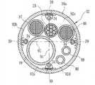
图9表示与弯曲部32的中心轴正交的横截面。该横截面能够通过两根假想线91以90°间隔划分为四个区域。假想线91为将相对于多个关节环38的中心轴在点对称的位置配置的一对连接销39连接的线,这两根假想线91在相邻的连接销39之间从中心轴方向观察以90度角度交差。在第一区间92a配置钳子通道19。在第二区域92b配置第一光导87。在第三区域92c配置信号电缆25及第二光导88,在第四区域92d配置送气管89和送水管90。FIG. 9 shows a cross section perpendicular to the central axis of the
通过弯曲部32的弯曲操作,作用于钳子通道19的横方向的力(横力)在通过角中心轴的对角方向增强。相对于角中心轴,在钳子通道19的大致对角位置配置信号电缆25,而且相对于由弯曲部32的弯曲操作引起的钳子通道19的弯曲行为,在取得刚性平衡的位置配置有刚性相比于钳子通道19稍次(次に高い)的信号电缆25。因此,能够相对于弯曲动作顺利地取得角弯曲一方的平衡。By the bending operation of the bending
另外,通过作用于钳子通道19的横力,使其它管类对角移动的力起作用。与此相对,利用基于加强框59的缩颈部71的偏移量,弯曲部32内的各区间92a~92d中,相对于第一区域92a的钳子通道19在对角位置的第三区域92c配置信号电缆25。由此,相对于弯曲部32的弯曲的钳子通道19的位移,能够在因其位移的影响带来的位置的变化最小的对角位置配置信号电缆25,能够相应地防止排列错乱。因此,对信号电缆25及光导88的损伤减少,能够抑制信号电缆自身的断裂等的产生。In addition, by the lateral force acting on the
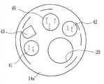
图10是相对于图3所示的内置物的配置例,将第一照明窗41和送气/送水喷嘴43的位置调换的图。在该情况下,如图11所示,通过积极地利用加强框59的缩颈部71的偏移量,在第一区间92a配置钳子通道19,在第二区域92b配置第一光导87。在第三区域92c配置信号电缆25、送气管89、送水管90,在第四区域92d配置第二光导88。FIG. 10 is a diagram in which the positions of the
在图10及图11的配置例中,与图9的配置例相同,能够获得减轻钳子通道19相对于信号电缆25的应力(ストレス)的效果,信号电缆的耐久性提高。另外,摄像透镜51的光轴和信号电缆25的偏移配置不限定于如图9及图11的配置。例如,也可以相对于弯曲部32的中心轴在钳子通道19的对角位置配置信号电缆25时,使信号电缆25进一步接近钳子通道19。在该情况下,通过使钳子通道19与信号电缆25接近,实现挠性部33的细径化。10 and 11, as in the arrangement example of FIG. 9, the effect of reducing the stress (stress) of the
如上,利用摄像装置26的加强框59,进行弯曲部32内的信号电缆25和钳子通道19的定位,而且,其它光导87、88等内置物也获得该加强框59的慢弯(緩い)位置限制效果。由此,即使在弯曲部32弯曲的情况下,在电缆固定部61附近,也能够抑制管类越过销39在各区域移动的排列错乱的产生。另外,在越过销39时,没有使得管类因销39而受到压迫,能够抑制信号电缆的断线的产生。而且,利用基于加强框59的各管的慢弯位置限制效果,成为在各区域92a~92d内确保各管类的间隙的平衡良好的配置,且也能够抑制因平衡不良引起的弯曲动作时的各管类的滑动阻力的增加。As above, using the
在本实施方式中,通过在棱镜53的后端侧即在配置于主电路基板57的下方的加强框59内设置子电路基板58、较短地加工原线65、或者将原线65折叠收纳于加强框59内等,能够使电缆固定部61和主电路基板57靠近。如图12(A)所示,其能够使摄像装置26的长度方向短小化L1的量。由此,在前端筒37内,能够使电缆固定部61位于比第一关节环38a更靠近前端侧。In this embodiment, by disposing the
另一方面,如图12(B)所示,在电缆固定部61位于第一关节环38a之后的后端侧的情况下,电缆固定部61正后方的部分成为刚性变化点,担心其应力集中而断线。与此相对,通过设定为图12(A)的电缆固定位置,即使在弯曲部32例如最大限弯曲的情况下,在电缆固定部61的附近信号电缆25弯曲也减小。由此,信号电缆25描绘慢弯曲线而弯曲,另外,作用于电缆固定部61的折弯力变小。其结果是信号电缆的耐久性提高。On the other hand, as shown in FIG. 12(B), when the
而且,在图12(B)中,由于具有刚性的电缆固定部61位于第一关节环38a内,因此,有可能与其它光导等发生干涉。在本实施方式中,由于具有柔软性的信号电缆25位于第一关节环38a内,因此这些担心也消除。这样,即使在弯曲部32以相同的角度弯曲的情况下,通过在前后方向改变电缆固定部61的位置,能够降低作用于电缆固定部61的弯曲力、及消除对其它管类的破损的担心。Moreover, in FIG. 12(B), since the rigid
另外,通过摄像装置26的短小化,能够将电缆固定部61配置于前端筒37内,因此,再加上加强框59的偏移作用的效果,能够进一步提高弯曲部32内的内置物的耐久性。另外,仅通过上述加强框59的偏移效果或前端筒37内的信号电缆25的配置,能够提高弯曲部32内的内置物的耐久性。因此,只要至少满足其一方,就能够实现本发明的课题。In addition, by reducing the size of the
在上述实施方式中,向加强框59内充填粘接剂作为密封树脂60。也可以代替该充填,通过在将粘接剂放入加强框59内的状态下设置棱镜保持部件54、子电路基板58等,将各内置物密封在加强框59内。In the above embodiment, the
另外,在上述实施方式中,使用主电路基板和子电路基板,但也可以省掉子电路基板。在该情况下,使用一端侧安装有摄像元件,使另一端侧弯曲为U字形的弯曲电路基板。该弯曲电路基板可以为柔性电路基板或者也可以为硬质的电路基板。In addition, in the above-described embodiments, the main circuit board and the sub-circuit board are used, but the sub-circuit board may be omitted. In this case, a curved circuit board is used in which an imaging element is mounted on one end side and the other end side is bent in a U-shape. The curved circuit substrate may be a flexible circuit substrate or a rigid circuit substrate.
在上述实施方式中,采用将利用棱镜使光轴弯曲的摄像元件横放方式,但也可以省掉棱镜而将摄像元件纵放。另外,将构成信号电缆的多根原线用粘接剂固定一体化,但也可以不将其一体化。另外,作为偏移部件的加强框设为导流槽(樋)状,但只要能够使透镜镜筒的光轴和信号电缆的中心轴偏移,则可以为筒状,也可以为板状。而且,固定偏移部件的对象物除镜筒之外,也可以为前端部主体。在该情况下,在前端部主体形成偏移部件的接收部,并对其嵌合偏移部件的前端部。In the above-mentioned embodiment, the imaging element whose optical axis is bent by the prism is installed horizontally, but the imaging element may be installed vertically without the prism. In addition, although the plurality of primary wires constituting the signal cable are fixed and integrated with an adhesive, they may not be integrated. In addition, the reinforcing frame as an offset member is formed in a flow channel (樋) shape, but it may be cylindrical or plate-shaped as long as the optical axis of the lens barrel and the central axis of the signal cable can be offset. Furthermore, the object to which the offset member is fixed may be the front end body other than the lens barrel. In this case, the receiving part of the offset member is formed in the front-end part main body, and the front-end|tip part of the offset member is fitted to it.
Claims (11)
Translated fromChinesePriority Applications (1)
| Application Number | Priority Date | Filing Date | Title |
|---|---|---|---|
| CN201510559728.2ACN105223684B (en) | 2011-03-30 | 2012-02-27 | Endoscope apparatus |
Applications Claiming Priority (2)
| Application Number | Priority Date | Filing Date | Title |
|---|---|---|---|
| JP2011074277AJP5250653B2 (en) | 2011-03-30 | 2011-03-30 | Endoscopic imaging apparatus and endoscope |
| JP2011-074277 | 2011-03-30 |
Related Child Applications (1)
| Application Number | Title | Priority Date | Filing Date |
|---|---|---|---|
| CN201510559728.2ADivisionCN105223684B (en) | 2011-03-30 | 2012-02-27 | Endoscope apparatus |
Publications (2)
| Publication Number | Publication Date |
|---|---|
| CN102727163Atrue CN102727163A (en) | 2012-10-17 |
| CN102727163B CN102727163B (en) | 2015-09-16 |
Family
ID=46984002
Family Applications (2)
| Application Number | Title | Priority Date | Filing Date |
|---|---|---|---|
| CN201510559728.2AActiveCN105223684B (en) | 2011-03-30 | 2012-02-27 | Endoscope apparatus |
| CN201210046690.5AActiveCN102727163B (en) | 2011-03-30 | 2012-02-27 | Endoscope and its camera device |
Family Applications Before (1)
| Application Number | Title | Priority Date | Filing Date |
|---|---|---|---|
| CN201510559728.2AActiveCN105223684B (en) | 2011-03-30 | 2012-02-27 | Endoscope apparatus |
Country Status (2)
| Country | Link |
|---|---|
| JP (1) | JP5250653B2 (en) |
| CN (2) | CN105223684B (en) |
Cited By (9)
| Publication number | Priority date | Publication date | Assignee | Title |
|---|---|---|---|---|
| CN105163647A (en)* | 2013-06-28 | 2015-12-16 | 奥林巴斯株式会社 | Imaging unit and endoscope device |
| CN105816142A (en)* | 2015-01-26 | 2016-08-03 | 富士胶片株式会社 | Optical device, electronic endoscope and manufacturing method of optical device |
| CN107072494A (en)* | 2015-06-16 | 2017-08-18 | 奥林巴斯株式会社 | Endoscope |
| CN107409172A (en)* | 2015-04-24 | 2017-11-28 | 日立汽车系统株式会社 | camera device |
| CN111035350A (en)* | 2019-12-30 | 2020-04-21 | 常州延顺光电科技有限公司 | Preparation method of snake bone device of endoscope |
| CN111065309A (en)* | 2017-09-01 | 2020-04-24 | 奥林巴斯株式会社 | Insertion part of endoscope |
| WO2020113808A1 (en)* | 2018-12-07 | 2020-06-11 | 上海英诺伟医疗器械有限公司 | Flexible catheter-based in vivo detection device and system |
| CN112657073A (en)* | 2019-10-16 | 2021-04-16 | 重庆海扶医疗科技股份有限公司 | Preparation method of ultrasonic tube and ultrasonic tube |
| CN113329676A (en)* | 2019-03-18 | 2021-08-31 | 奥林巴斯株式会社 | Holding frame, endoscope distal end structure, and endoscope |
Families Citing this family (9)
| Publication number | Priority date | Publication date | Assignee | Title |
|---|---|---|---|---|
| JP5558399B2 (en)* | 2011-03-30 | 2014-07-23 | 富士フイルム株式会社 | Endoscopic imaging device |
| JP6655343B2 (en)* | 2015-10-15 | 2020-02-26 | 富士フイルム株式会社 | Endoscope |
| WO2017217025A1 (en)* | 2016-06-17 | 2017-12-21 | オリンパス株式会社 | Endoscope device |
| JP6230771B1 (en)* | 2016-06-17 | 2017-11-15 | オリンパス株式会社 | Endoscope device |
| JP6650378B2 (en)* | 2016-09-08 | 2020-02-19 | 富士フイルム株式会社 | Endoscope |
| CN113365544B (en)* | 2019-02-15 | 2024-06-28 | 奥林巴斯株式会社 | Endoscope, grounding method, and grounding method of front end portion of endoscope |
| WO2020188688A1 (en)* | 2019-03-18 | 2020-09-24 | オリンパス株式会社 | Tip end unit of endoscope |
| DE102020134036A1 (en)* | 2020-12-17 | 2022-06-23 | Ambu A/S | Endoscope with an endoscope handle with a disconnect device |
| JP7555298B2 (en) | 2021-04-21 | 2024-09-24 | 富士フイルム株式会社 | Endoscope imaging device and endoscope |
Citations (8)
| Publication number | Priority date | Publication date | Assignee | Title |
|---|---|---|---|---|
| US5873816A (en)* | 1994-11-02 | 1999-02-23 | Olympus Optical Co., Ltd. | Electronic endoscope having an insertional portion a part of which is a conductive armor |
| US20020151768A1 (en)* | 2000-08-02 | 2002-10-17 | Haruo Akiba | Observation window washing device of endoscope |
| JP2005204944A (en)* | 2004-01-22 | 2005-08-04 | Chinontec Kk | Endoscope |
| JP2006141726A (en)* | 2004-11-19 | 2006-06-08 | Olympus Corp | Solid-state image sensor unit |
| JP2007097883A (en)* | 2005-10-05 | 2007-04-19 | Olympus Corp | Bending section structure for endoscope |
| CN1953697A (en)* | 2004-05-14 | 2007-04-25 | 奥林巴斯医疗株式会社 | Electronic endoscope |
| CN101098653A (en)* | 2005-01-07 | 2008-01-02 | 奥林巴斯医疗株式会社 | Insertion part for endoscope |
| CN101548874A (en)* | 2004-07-05 | 2009-10-07 | 奥林巴斯医疗株式会社 | Electronic endoscope |
Family Cites Families (23)
| Publication number | Priority date | Publication date | Assignee | Title |
|---|---|---|---|---|
| JPH0664243B2 (en)* | 1986-04-30 | 1994-08-22 | オリンパス光学工業株式会社 | Endoscope |
| JPS6321618A (en)* | 1986-07-15 | 1988-01-29 | Olympus Optical Co Ltd | Endoscope |
| JP2735101B2 (en)* | 1986-12-08 | 1998-04-02 | オリンパス光学工業株式会社 | Imaging device |
| JPS63119736A (en)* | 1987-10-08 | 1988-05-24 | オリンパス光学工業株式会社 | Endoscope |
| JP2610241B2 (en)* | 1990-11-29 | 1997-05-14 | 富士写真光機株式会社 | Wiring structure to solid-state image sensor in electronic endoscope |
| JP3686110B2 (en)* | 1994-11-10 | 2005-08-24 | オリンパス株式会社 | Endoscope |
| JPH0990243A (en)* | 1995-09-22 | 1997-04-04 | Olympus Optical Co Ltd | Image pickup device |
| JP3905152B2 (en)* | 1996-07-05 | 2007-04-18 | オリンパス株式会社 | Imaging device for endoscope |
| JP4016459B2 (en)* | 1997-08-20 | 2007-12-05 | フジノン株式会社 | Stereoscopic endoscope |
| JP3742514B2 (en)* | 1998-10-16 | 2006-02-08 | オリンパス株式会社 | Imaging device |
| JP2000210252A (en)* | 1999-01-25 | 2000-08-02 | Sony Corp | Solid-state imaging device |
| JP2001212074A (en)* | 2000-02-07 | 2001-08-07 | Olympus Optical Co Ltd | Endoscope |
| JP2003209751A (en)* | 2002-01-16 | 2003-07-25 | Olympus Optical Co Ltd | Solid-state imaging apparatus |
| JP4484044B2 (en)* | 2004-07-29 | 2010-06-16 | 富士フイルム株式会社 | Ultrasound endoscope |
| JP2007286613A (en)* | 2006-03-22 | 2007-11-01 | Fujinon Corp | Endoscopic apparatus |
| JP2007301083A (en)* | 2006-05-10 | 2007-11-22 | Fujinon Corp | Endoscope |
| JP4682158B2 (en)* | 2007-01-16 | 2011-05-11 | オリンパスメディカルシステムズ株式会社 | Imaging device |
| JP5283343B2 (en)* | 2007-03-29 | 2013-09-04 | 富士フイルム株式会社 | Ultrasound endoscope |
| JP2009153902A (en)* | 2007-12-27 | 2009-07-16 | Fujinon Corp | Electronic endoscope |
| JP2010042120A (en)* | 2008-08-12 | 2010-02-25 | Fujifilm Corp | Endoscope |
| JP5279367B2 (en)* | 2008-07-01 | 2013-09-04 | 富士フイルム株式会社 | Endoscope |
| JP2010057749A (en)* | 2008-09-04 | 2010-03-18 | Fujifilm Corp | Wiring module, its manufacturing method, and endoscope |
| JP5558399B2 (en)* | 2011-03-30 | 2014-07-23 | 富士フイルム株式会社 | Endoscopic imaging device |
- 2011
- 2011-03-30JPJP2011074277Apatent/JP5250653B2/enactiveActive
- 2012
- 2012-02-27CNCN201510559728.2Apatent/CN105223684B/enactiveActive
- 2012-02-27CNCN201210046690.5Apatent/CN102727163B/enactiveActive
Patent Citations (8)
| Publication number | Priority date | Publication date | Assignee | Title |
|---|---|---|---|---|
| US5873816A (en)* | 1994-11-02 | 1999-02-23 | Olympus Optical Co., Ltd. | Electronic endoscope having an insertional portion a part of which is a conductive armor |
| US20020151768A1 (en)* | 2000-08-02 | 2002-10-17 | Haruo Akiba | Observation window washing device of endoscope |
| JP2005204944A (en)* | 2004-01-22 | 2005-08-04 | Chinontec Kk | Endoscope |
| CN1953697A (en)* | 2004-05-14 | 2007-04-25 | 奥林巴斯医疗株式会社 | Electronic endoscope |
| CN101548874A (en)* | 2004-07-05 | 2009-10-07 | 奥林巴斯医疗株式会社 | Electronic endoscope |
| JP2006141726A (en)* | 2004-11-19 | 2006-06-08 | Olympus Corp | Solid-state image sensor unit |
| CN101098653A (en)* | 2005-01-07 | 2008-01-02 | 奥林巴斯医疗株式会社 | Insertion part for endoscope |
| JP2007097883A (en)* | 2005-10-05 | 2007-04-19 | Olympus Corp | Bending section structure for endoscope |
Cited By (13)
| Publication number | Priority date | Publication date | Assignee | Title |
|---|---|---|---|---|
| CN105163647A (en)* | 2013-06-28 | 2015-12-16 | 奥林巴斯株式会社 | Imaging unit and endoscope device |
| CN105816142A (en)* | 2015-01-26 | 2016-08-03 | 富士胶片株式会社 | Optical device, electronic endoscope and manufacturing method of optical device |
| CN107409172B (en)* | 2015-04-24 | 2020-05-19 | 日立汽车系统株式会社 | Image pickup apparatus |
| CN107409172A (en)* | 2015-04-24 | 2017-11-28 | 日立汽车系统株式会社 | camera device |
| CN107072494A (en)* | 2015-06-16 | 2017-08-18 | 奥林巴斯株式会社 | Endoscope |
| CN111065309A (en)* | 2017-09-01 | 2020-04-24 | 奥林巴斯株式会社 | Insertion part of endoscope |
| CN111065309B (en)* | 2017-09-01 | 2022-05-24 | 奥林巴斯株式会社 | Insertion part of endoscope |
| US11903565B2 (en) | 2018-07-12 | 2024-02-20 | Innovex Medical Co., Ltd | Flexible catheter-based in vivo detection device and system |
| WO2020113808A1 (en)* | 2018-12-07 | 2020-06-11 | 上海英诺伟医疗器械有限公司 | Flexible catheter-based in vivo detection device and system |
| CN113329676A (en)* | 2019-03-18 | 2021-08-31 | 奥林巴斯株式会社 | Holding frame, endoscope distal end structure, and endoscope |
| CN113329676B (en)* | 2019-03-18 | 2024-05-24 | 奥林巴斯株式会社 | Holding frame, endoscope distal end structure, and endoscope |
| CN112657073A (en)* | 2019-10-16 | 2021-04-16 | 重庆海扶医疗科技股份有限公司 | Preparation method of ultrasonic tube and ultrasonic tube |
| CN111035350A (en)* | 2019-12-30 | 2020-04-21 | 常州延顺光电科技有限公司 | Preparation method of snake bone device of endoscope |
Also Published As
| Publication number | Publication date |
|---|---|
| CN105223684A (en) | 2016-01-06 |
| CN102727163B (en) | 2015-09-16 |
| JP2012205808A (en) | 2012-10-25 |
| JP5250653B2 (en) | 2013-07-31 |
| CN105223684B (en) | 2018-04-06 |
Similar Documents
| Publication | Publication Date | Title |
|---|---|---|
| CN102727163B (en) | Endoscope and its camera device | |
| CN100438818C (en) | Endoscope connection device, endoscope cable lead-out unit, and endoscope device | |
| JP5558399B2 (en) | Endoscopic imaging device | |
| JP5192559B2 (en) | Endoscope | |
| CN112423646B (en) | Front end of endoscope | |
| CN104812290A (en) | Electronic endoscope | |
| CN106886089B (en) | Endoscope with a detachable handle | |
| CN103027661B (en) | Camera module for endoscope and endoscope | |
| US20120197081A1 (en) | Imaging device and electronic endoscope having imaging device | |
| US9226646B2 (en) | Substrate connecting structure | |
| US20170035279A1 (en) | Image pickup unit and electronic endoscope including the image pickup unit | |
| JP2009153902A (en) | Electronic endoscope | |
| JP6322348B1 (en) | Imaging unit | |
| JP6109079B2 (en) | Cable connection structure and imaging device | |
| JP6461816B2 (en) | Imaging apparatus and endoscope apparatus | |
| CN105361838A (en) | Endoscope | |
| JP2008253451A (en) | Distal end structure of endoscope | |
| US10098522B2 (en) | Endoscope | |
| WO2015159619A1 (en) | Bending endoscope tube, endoscope, and method for manufacturing bending endoscope tube | |
| US8911241B2 (en) | Substrate connection structure | |
| JP5399305B2 (en) | Imaging apparatus and endoscope | |
| US9060447B2 (en) | Substrate structure | |
| JP2011200338A (en) | Electronic endoscope | |
| US10080480B2 (en) | Endoscope | |
| JP6120592B2 (en) | Endoscope imaging unit |
Legal Events
| Date | Code | Title | Description |
|---|---|---|---|
| C06 | Publication | ||
| PB01 | Publication | ||
| C10 | Entry into substantive examination | ||
| SE01 | Entry into force of request for substantive examination | ||
| C14 | Grant of patent or utility model | ||
| GR01 | Patent grant |