CN102724838A - Slip connection device - Google Patents
Slip connection deviceDownload PDFInfo
- Publication number
- CN102724838A CN102724838ACN2012102207040ACN201210220704ACN102724838ACN 102724838 ACN102724838 ACN 102724838ACN 2012102207040 ACN2012102207040 ACN 2012102207040ACN 201210220704 ACN201210220704 ACN 201210220704ACN 102724838 ACN102724838 ACN 102724838A
- Authority
- CN
- China
- Prior art keywords
- slider
- sliding connection
- elastic ring
- connection device
- cage
- Prior art date
- Legal status (The legal status is an assumption and is not a legal conclusion. Google has not performed a legal analysis and makes no representation as to the accuracy of the status listed.)
- Pending
Links
Images


Classifications
- H—ELECTRICITY
- H05—ELECTRIC TECHNIQUES NOT OTHERWISE PROVIDED FOR
- H05K—PRINTED CIRCUITS; CASINGS OR CONSTRUCTIONAL DETAILS OF ELECTRIC APPARATUS; MANUFACTURE OF ASSEMBLAGES OF ELECTRICAL COMPONENTS
- H05K7/00—Constructional details common to different types of electric apparatus
- H05K7/14—Mounting supporting structure in casing or on frame or rack
- G—PHYSICS
- G06—COMPUTING OR CALCULATING; COUNTING
- G06F—ELECTRIC DIGITAL DATA PROCESSING
- G06F1/00—Details not covered by groups G06F3/00 - G06F13/00 and G06F21/00
- G06F1/16—Constructional details or arrangements
- G06F1/1613—Constructional details or arrangements for portable computers
- G06F1/1615—Constructional details or arrangements for portable computers with several enclosures having relative motions, each enclosure supporting at least one I/O or computing function
- G06F1/1624—Constructional details or arrangements for portable computers with several enclosures having relative motions, each enclosure supporting at least one I/O or computing function with sliding enclosures, e.g. sliding keyboard or display
- H—ELECTRICITY
- H04—ELECTRIC COMMUNICATION TECHNIQUE
- H04M—TELEPHONIC COMMUNICATION
- H04M1/00—Substation equipment, e.g. for use by subscribers
- H04M1/02—Constructional features of telephone sets
- H04M1/0202—Portable telephone sets, e.g. cordless phones, mobile phones or bar type handsets
- H04M1/0206—Portable telephones comprising a plurality of mechanically joined movable body parts, e.g. hinged housings
- H04M1/0208—Portable telephones comprising a plurality of mechanically joined movable body parts, e.g. hinged housings characterized by the relative motions of the body parts
- H04M1/0235—Slidable or telescopic telephones, i.e. with a relative translation movement of the body parts; Telephones using a combination of translation and other relative motions of the body parts
- H04M1/0237—Sliding mechanism with one degree of freedom
- H—ELECTRICITY
- H04—ELECTRIC COMMUNICATION TECHNIQUE
- H04M—TELEPHONIC COMMUNICATION
- H04M1/00—Substation equipment, e.g. for use by subscribers
- H04M1/02—Constructional features of telephone sets
- H04M1/0202—Portable telephone sets, e.g. cordless phones, mobile phones or bar type handsets
- H04M1/0206—Portable telephones comprising a plurality of mechanically joined movable body parts, e.g. hinged housings
- H04M1/0208—Portable telephones comprising a plurality of mechanically joined movable body parts, e.g. hinged housings characterized by the relative motions of the body parts
- H04M1/0214—Foldable telephones, i.e. with body parts pivoting to an open position around an axis parallel to the plane they define in closed position
Landscapes
- Engineering & Computer Science (AREA)
- Physics & Mathematics (AREA)
- Theoretical Computer Science (AREA)
- General Physics & Mathematics (AREA)
- Human Computer Interaction (AREA)
- General Engineering & Computer Science (AREA)
- Computer Hardware Design (AREA)
- Mathematical Physics (AREA)
- Signal Processing (AREA)
- Microelectronics & Electronic Packaging (AREA)
- Calculators And Similar Devices (AREA)
- Casings For Electric Apparatus (AREA)
- Telephone Set Structure (AREA)
Abstract
Translated fromChineseDescription
Translated fromChinese技术领域technical field
本发明涉及一种连接两个元件的滑动连接装置。The invention relates to a sliding connection device for connecting two elements.
背景技术Background technique
在一些电子产品中,例如数码摄像机,包括液晶显示屏部分和握持部分,有了能更加方便用户的拍摄操作,有时需要握持部分能够相对于液晶显示屏部分滑动以调解二者之间的距离。虽然现有的滑轨能够实现上述需求,但是提供一种新的结构简单的连接两个元件的滑动连接装置是有益的。In some electronic products, such as a digital video camera, which includes a liquid crystal display screen and a grip part, it is sometimes necessary for the grip part to be able to slide relative to the liquid crystal display part to adjust the relationship between the two because of the user-friendly shooting operation. distance. Although the existing slide rails can meet the above needs, it is beneficial to provide a new sliding connection device for connecting two elements with a simple structure.
发明内容Contents of the invention
有鉴于此,本发明提供一种连接两个元件的滑动连接装置。In view of this, the present invention provides a sliding connection device for connecting two elements.
本发明提供一种滑动连接装置,用于连接一第一元件和一第二元件,并且使该第一元件能相对该第二元件滑动,该滑动连接装置包括滑块、保持架和弹性圈,该滑块与该第一元件固定连接,该保持架与该第二元件固定连接,该弹性圈套在该滑块的侧壁上,该保持架包括一滑动连接部,该滑动连接部连接于该滑块,并且能相对于该滑块滑动,该滑动连接部包括支撑片,该支撑片位于该弹性圈和该滑块的侧壁之间,该支撑片用于张紧该弹性圈,该保持架相对于该滑块滑动至一期待位置后,该保持架因该支撑片受到该弹性圈的弹力作用而能够保持在该期待位置。The invention provides a sliding connection device for connecting a first element and a second element, and enabling the first element to slide relative to the second element, the sliding connection device includes a slider, a cage and an elastic ring, The slider is fixedly connected with the first element, the cage is fixedly connected with the second element, the elastic ring is covered on the side wall of the slider, the cage includes a sliding connection part, and the sliding connection part is connected to the slider, and can slide relative to the slider, the sliding connection part includes a support piece, the support piece is located between the elastic ring and the side wall of the slider, the support piece is used to tension the elastic ring, the holding After the frame slides to a desired position relative to the slider, the retainer can be kept at the desired position due to the elastic force of the elastic ring on the supporting piece.
本发明的滑动连接装置结构简单,组装方便。The sliding connection device of the present invention has simple structure and convenient assembly.
附图说明Description of drawings
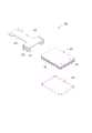
图1为本发明的滑动连接装置的立体图。Fig. 1 is a perspective view of the sliding connection device of the present invention.
图2为本发明的滑动连接装置的分解图。Fig. 2 is an exploded view of the sliding connection device of the present invention.
图3为本发明的滑动连接装置的另一角度的分解图。Fig. 3 is an exploded view of another angle of the sliding connection device of the present invention.
图4为本发明的滑动连接装置的剖视图。Fig. 4 is a cross-sectional view of the sliding connection device of the present invention.
主要元件符号说明Description of main component symbols
如下具体实施方式将结合上述附图进一步说明本发明。The following specific embodiments will further illustrate the present invention in conjunction with the above-mentioned drawings.
具体实施方式Detailed ways
请参考图1,电子装置100包括本体10和握持部20,该本体10和握持部20通过一滑动连接装置30连接在一起,并且该握持部20能相对于本体10滑动。该电子装置100可为数码摄像机,此时,该本体10包括有液晶显示器,用户可以用手握住该握持部20进行拍摄。Please refer to FIG. 1 , an electronic device 100 includes a body 10 and a handle 20 , the body 10 and the handle 20 are connected together by a
请参考图2和图3,该滑动连接装置30包括滑块40、保持架50和弹性圈60,该滑块40与该握持部20固定连接,该保持架50与该本体10固定连接,该弹性圈60套在该滑块40的侧壁41上,该保持架50包括一滑动连接部51,该滑动连接部51连接于该滑块40,并且能相对于该滑块40滑动,该滑动连接部51包括支撑片52,该支撑片52位于该弹性圈60和该滑块40的侧壁41之间,该支撑片52用于张紧该弹性圈60,该保持架50相对于该滑块40滑动至一期待位置后,该保持架50因该支撑片受到该弹性圈60的弹力作用而能够保持在该期待位置。Please refer to FIG. 2 and FIG. 3 , the
在本实施方式中,该滑块40为方形薄板,其侧壁41上设置有凹槽42,该弹性圈60收容在该凹槽42中,该弹性圈60由弹性材料制成,例如具有弹性的尼龙,如此,该弹性圈60能紧紧的套在该侧壁41的凹槽42内。In this embodiment, the
该保持架50还包括一长条形的固定连接部53,该固定连接部53的一端与该本体10固定连接,该滑动连接部51连接于该固定连接部53的另一端。在本实施方式中,该滑动连接部51包括平板511和弯折部512,该平板511和该固定连接部53大致垂直,该弯折部512共有两个,其分别形成于该平板511的相对的两端,每个弯折部512包括自平板511的末端伸出的水平部513以及形成于水平部513的末端且与水平部513大致垂直的竖直部514。该平板511和弯折部512构成了一个滑轨,该滑轨扣在该滑块40上,使得该滑块40能够沿着滑轨滑动。The
请参考图4,在本实施方式中,每个弯折部512包括两个相互间隔开的水平部513,该支撑片52自该平板511的一端伸出且位于两个水平部513之间,该两个水平部513位于弹性圈60之上并且对弹性圈60施加压力。Please refer to FIG. 4 , in this embodiment, each
每个弯折部512与该支撑片52之间的距离L小于弹性圈60的直径D,如此,在保持架50相对滑块40滑动过程中,例如沿图4中的箭头方向移动一小段距离,弹性圈60的一部分A自凹槽42中进入弯折部512与该支撑片52之间的间隙B,以及原本位于支撑片52之上的弹性圈60的一部分C进入另一弯折部512与该支撑片52之间的间隙E。在整个移动过程中,持续有弹性圈60的一部分进入间隙B和E之间,由此对弯折部512与该支撑片52的移动产生阻力,会使得保持架50相对滑块40滑动更加平稳,并且对将保持架50定位于期待位置亦有帮助。The distance L between each
Claims (6)
Translated fromChinesePriority Applications (3)
| Application Number | Priority Date | Filing Date | Title |
|---|---|---|---|
| CN2012102207040ACN102724838A (en) | 2012-06-29 | 2012-06-29 | Slip connection device |
| TW101124476ATW201401987A (en) | 2012-06-29 | 2012-07-06 | Slidable connecting device |
| US13/693,043US20140002970A1 (en) | 2012-06-29 | 2012-12-04 | Slidable connecting device and electronic device using the same |
Applications Claiming Priority (1)
| Application Number | Priority Date | Filing Date | Title |
|---|---|---|---|
| CN2012102207040ACN102724838A (en) | 2012-06-29 | 2012-06-29 | Slip connection device |
Publications (1)
| Publication Number | Publication Date |
|---|---|
| CN102724838Atrue CN102724838A (en) | 2012-10-10 |
Family
ID=46950431
Family Applications (1)
| Application Number | Title | Priority Date | Filing Date |
|---|---|---|---|
| CN2012102207040APendingCN102724838A (en) | 2012-06-29 | 2012-06-29 | Slip connection device |
Country Status (3)
| Country | Link |
|---|---|
| US (1) | US20140002970A1 (en) |
| CN (1) | CN102724838A (en) |
| TW (1) | TW201401987A (en) |
Cited By (2)
| Publication number | Priority date | Publication date | Assignee | Title |
|---|---|---|---|---|
| CN104676358A (en)* | 2013-11-30 | 2015-06-03 | 全亿大科技(佛山)有限公司 | Lamp |
| CN107278083A (en)* | 2016-04-07 | 2017-10-20 | 广达电脑股份有限公司 | Component carrier |
Families Citing this family (1)
| Publication number | Priority date | Publication date | Assignee | Title |
|---|---|---|---|---|
| EP3267646B1 (en)* | 2016-07-06 | 2021-06-02 | Nxp B.V. | Iq mismatch correction module |
Citations (3)
| Publication number | Priority date | Publication date | Assignee | Title |
|---|---|---|---|---|
| US20070273786A1 (en)* | 2006-05-26 | 2007-11-29 | Samsung Electronics Co., Ltd. | Portable electronic device and camera |
| CN201821607U (en)* | 2010-10-08 | 2011-05-04 | 宗皓科技股份有限公司 | Sliding positioning module for mobile devices |
| CN202183921U (en)* | 2011-07-11 | 2012-04-04 | 杭州安费诺飞凤通信部品有限公司 | Slide plate hinge for mancarried electronic aid terminal |
Family Cites Families (4)
| Publication number | Priority date | Publication date | Assignee | Title |
|---|---|---|---|---|
| JP2003319042A (en)* | 2002-04-25 | 2003-11-07 | Matsushita Electric Ind Co Ltd | Mobile terminal equipment |
| WO2009110454A1 (en)* | 2008-03-05 | 2009-09-11 | 京セラ株式会社 | Open-close type compact electronic device |
| CN102990675B (en)* | 2011-09-08 | 2015-04-15 | 鸿富锦精密工业(深圳)有限公司 | Robot arm component |
| TWI647559B (en)* | 2013-04-24 | 2019-01-11 | 日商半導體能源研究所股份有限公司 | Display device |
- 2012
- 2012-06-29CNCN2012102207040Apatent/CN102724838A/enactivePending
- 2012-07-06TWTW101124476Apatent/TW201401987A/enunknown
- 2012-12-04USUS13/693,043patent/US20140002970A1/ennot_activeAbandoned
Patent Citations (3)
| Publication number | Priority date | Publication date | Assignee | Title |
|---|---|---|---|---|
| US20070273786A1 (en)* | 2006-05-26 | 2007-11-29 | Samsung Electronics Co., Ltd. | Portable electronic device and camera |
| CN201821607U (en)* | 2010-10-08 | 2011-05-04 | 宗皓科技股份有限公司 | Sliding positioning module for mobile devices |
| CN202183921U (en)* | 2011-07-11 | 2012-04-04 | 杭州安费诺飞凤通信部品有限公司 | Slide plate hinge for mancarried electronic aid terminal |
Cited By (3)
| Publication number | Priority date | Publication date | Assignee | Title |
|---|---|---|---|---|
| CN104676358A (en)* | 2013-11-30 | 2015-06-03 | 全亿大科技(佛山)有限公司 | Lamp |
| CN107278083A (en)* | 2016-04-07 | 2017-10-20 | 广达电脑股份有限公司 | Component carrier |
| CN107278083B (en)* | 2016-04-07 | 2019-06-14 | 广达电脑股份有限公司 | component carrier |
Also Published As
| Publication number | Publication date |
|---|---|
| TW201401987A (en) | 2014-01-01 |
| US20140002970A1 (en) | 2014-01-02 |
Similar Documents
| Publication | Publication Date | Title |
|---|---|---|
| EP2778654A3 (en) | Tissue cassette with biasing element | |
| EP3315534A4 (en) | POLYAMIDE IMIDE PRECURSOR, POLYAMIDE IMIDE FILM, AND DISPLAY DEVICE COMPRISING THE SAME | |
| JP2012208208A5 (en) | ||
| CN102724838A (en) | Slip connection device | |
| CN204935460U (en) | A kind of side surface positioning device | |
| CN203857240U (en) | Universal type wall hanging frame for television | |
| EP2775192A3 (en) | Display device and point-of-sale system having the display device | |
| EP2706757A3 (en) | Electronic device and image projection apparatus | |
| EP2778796A3 (en) | Fixing device and image forming apparatus incorporating same | |
| EP2851205A3 (en) | Liquid containing vessel, liquid containing body, substrate support member, and unit | |
| TW200717000A (en) | A device support, and a handler including the device support | |
| EP2650241A3 (en) | Sheet loading unit, image forming apparatus and image reading apparatus | |
| US9845818B2 (en) | Coupling device and lamp apparatus having the same | |
| MA45980A (en) | SYSTEMS AND METHODS FOR ADJUSTING A BASAL / BOLUS RATIO IN AN INSULIN DIET | |
| CN105650427A (en) | Supporting device | |
| US9897247B2 (en) | Positioning device | |
| CN106378736B (en) | Liquid crystal display positioning clamping device | |
| US8763964B2 (en) | Support bracket for electronic device | |
| US9854113B1 (en) | Support device of contact image sensor of image capture apparatus | |
| EP2367409A3 (en) | Stand for information processing apparatus | |
| CN104676216B (en) | Adjustable supporting | |
| CN102568313A (en) | Display equipment supporting device | |
| CN208138791U (en) | Improved lifting bracket | |
| CN203982262U (en) | Electronic device combination | |
| CN204977952U (en) | A blackboard for science technology educates usefulness |
Legal Events
| Date | Code | Title | Description |
|---|---|---|---|
| C06 | Publication | ||
| PB01 | Publication | ||
| C10 | Entry into substantive examination | ||
| SE01 | Entry into force of request for substantive examination | ||
| C02 | Deemed withdrawal of patent application after publication (patent law 2001) | ||
| WD01 | Invention patent application deemed withdrawn after publication | Application publication date:20121010 |