CN102711642A - Systems and methods for controlling the use and operation of a class of disparate therapeutic devices - Google Patents
Systems and methods for controlling the use and operation of a class of disparate therapeutic devicesDownload PDFInfo
- Publication number
- CN102711642A CN102711642ACN2010800528544ACN201080052854ACN102711642ACN 102711642 ACN102711642 ACN 102711642ACN 2010800528544 ACN2010800528544 ACN 2010800528544ACN 201080052854 ACN201080052854 ACN 201080052854ACN 102711642 ACN102711642 ACN 102711642A
- Authority
- CN
- China
- Prior art keywords
- lesion
- level
- lesions
- graphical
- user
- Prior art date
- Legal status (The legal status is an assumption and is not a legal conclusion. Google has not performed a legal analysis and makes no representation as to the accuracy of the status listed.)
- Granted
Links
Images


Classifications
- A—HUMAN NECESSITIES
- A61—MEDICAL OR VETERINARY SCIENCE; HYGIENE
- A61B—DIAGNOSIS; SURGERY; IDENTIFICATION
- A61B18/00—Surgical instruments, devices or methods for transferring non-mechanical forms of energy to or from the body
- A61B18/04—Surgical instruments, devices or methods for transferring non-mechanical forms of energy to or from the body by heating
- A61B18/12—Surgical instruments, devices or methods for transferring non-mechanical forms of energy to or from the body by heating by passing a current through the tissue to be heated, e.g. high-frequency current
- A61B18/1206—Generators therefor
- A—HUMAN NECESSITIES
- A61—MEDICAL OR VETERINARY SCIENCE; HYGIENE
- A61B—DIAGNOSIS; SURGERY; IDENTIFICATION
- A61B18/00—Surgical instruments, devices or methods for transferring non-mechanical forms of energy to or from the body
- A61B18/04—Surgical instruments, devices or methods for transferring non-mechanical forms of energy to or from the body by heating
- A61B18/12—Surgical instruments, devices or methods for transferring non-mechanical forms of energy to or from the body by heating by passing a current through the tissue to be heated, e.g. high-frequency current
- A61B18/14—Probes or electrodes therefor
- A61B18/1485—Probes or electrodes therefor having a short rigid shaft for accessing the inner body through natural openings
- A—HUMAN NECESSITIES
- A61—MEDICAL OR VETERINARY SCIENCE; HYGIENE
- A61B—DIAGNOSIS; SURGERY; IDENTIFICATION
- A61B18/00—Surgical instruments, devices or methods for transferring non-mechanical forms of energy to or from the body
- A61B18/04—Surgical instruments, devices or methods for transferring non-mechanical forms of energy to or from the body by heating
- A61B18/12—Surgical instruments, devices or methods for transferring non-mechanical forms of energy to or from the body by heating by passing a current through the tissue to be heated, e.g. high-frequency current
- A61B18/14—Probes or electrodes therefor
- A61B18/1492—Probes or electrodes therefor having a flexible, catheter-like structure, e.g. for heart ablation
- A—HUMAN NECESSITIES
- A61—MEDICAL OR VETERINARY SCIENCE; HYGIENE
- A61B—DIAGNOSIS; SURGERY; IDENTIFICATION
- A61B34/00—Computer-aided surgery; Manipulators or robots specially adapted for use in surgery
- A61B34/20—Surgical navigation systems; Devices for tracking or guiding surgical instruments, e.g. for frameless stereotaxis
- A—HUMAN NECESSITIES
- A61—MEDICAL OR VETERINARY SCIENCE; HYGIENE
- A61B—DIAGNOSIS; SURGERY; IDENTIFICATION
- A61B34/00—Computer-aided surgery; Manipulators or robots specially adapted for use in surgery
- A61B34/25—User interfaces for surgical systems
- G—PHYSICS
- G06—COMPUTING OR CALCULATING; COUNTING
- G06F—ELECTRIC DIGITAL DATA PROCESSING
- G06F3/00—Input arrangements for transferring data to be processed into a form capable of being handled by the computer; Output arrangements for transferring data from processing unit to output unit, e.g. interface arrangements
- G06F3/01—Input arrangements or combined input and output arrangements for interaction between user and computer
- G06F3/048—Interaction techniques based on graphical user interfaces [GUI]
- G06F3/0481—Interaction techniques based on graphical user interfaces [GUI] based on specific properties of the displayed interaction object or a metaphor-based environment, e.g. interaction with desktop elements like windows or icons, or assisted by a cursor's changing behaviour or appearance
- G06F3/04817—Interaction techniques based on graphical user interfaces [GUI] based on specific properties of the displayed interaction object or a metaphor-based environment, e.g. interaction with desktop elements like windows or icons, or assisted by a cursor's changing behaviour or appearance using icons
- G—PHYSICS
- G06—COMPUTING OR CALCULATING; COUNTING
- G06F—ELECTRIC DIGITAL DATA PROCESSING
- G06F3/00—Input arrangements for transferring data to be processed into a form capable of being handled by the computer; Output arrangements for transferring data from processing unit to output unit, e.g. interface arrangements
- G06F3/01—Input arrangements or combined input and output arrangements for interaction between user and computer
- G06F3/048—Interaction techniques based on graphical user interfaces [GUI]
- G06F3/0484—Interaction techniques based on graphical user interfaces [GUI] for the control of specific functions or operations, e.g. selecting or manipulating an object, an image or a displayed text element, setting a parameter value or selecting a range
- G06F3/04847—Interaction techniques to control parameter settings, e.g. interaction with sliders or dials
- G—PHYSICS
- G16—INFORMATION AND COMMUNICATION TECHNOLOGY [ICT] SPECIALLY ADAPTED FOR SPECIFIC APPLICATION FIELDS
- G16H—HEALTHCARE INFORMATICS, i.e. INFORMATION AND COMMUNICATION TECHNOLOGY [ICT] SPECIALLY ADAPTED FOR THE HANDLING OR PROCESSING OF MEDICAL OR HEALTHCARE DATA
- G16H40/00—ICT specially adapted for the management or administration of healthcare resources or facilities; ICT specially adapted for the management or operation of medical equipment or devices
- G16H40/60—ICT specially adapted for the management or administration of healthcare resources or facilities; ICT specially adapted for the management or operation of medical equipment or devices for the operation of medical equipment or devices
- G16H40/63—ICT specially adapted for the management or administration of healthcare resources or facilities; ICT specially adapted for the management or operation of medical equipment or devices for the operation of medical equipment or devices for local operation
- A—HUMAN NECESSITIES
- A61—MEDICAL OR VETERINARY SCIENCE; HYGIENE
- A61B—DIAGNOSIS; SURGERY; IDENTIFICATION
- A61B18/00—Surgical instruments, devices or methods for transferring non-mechanical forms of energy to or from the body
- A61B18/02—Surgical instruments, devices or methods for transferring non-mechanical forms of energy to or from the body by cooling, e.g. cryogenic techniques
- A—HUMAN NECESSITIES
- A61—MEDICAL OR VETERINARY SCIENCE; HYGIENE
- A61B—DIAGNOSIS; SURGERY; IDENTIFICATION
- A61B18/00—Surgical instruments, devices or methods for transferring non-mechanical forms of energy to or from the body
- A61B18/04—Surgical instruments, devices or methods for transferring non-mechanical forms of energy to or from the body by heating
- A61B18/08—Surgical instruments, devices or methods for transferring non-mechanical forms of energy to or from the body by heating by means of electrically-heated probes
- A—HUMAN NECESSITIES
- A61—MEDICAL OR VETERINARY SCIENCE; HYGIENE
- A61B—DIAGNOSIS; SURGERY; IDENTIFICATION
- A61B18/00—Surgical instruments, devices or methods for transferring non-mechanical forms of energy to or from the body
- A61B18/04—Surgical instruments, devices or methods for transferring non-mechanical forms of energy to or from the body by heating
- A61B18/12—Surgical instruments, devices or methods for transferring non-mechanical forms of energy to or from the body by heating by passing a current through the tissue to be heated, e.g. high-frequency current
- A61B18/14—Probes or electrodes therefor
- A61B18/1477—Needle-like probes
- A—HUMAN NECESSITIES
- A61—MEDICAL OR VETERINARY SCIENCE; HYGIENE
- A61B—DIAGNOSIS; SURGERY; IDENTIFICATION
- A61B18/00—Surgical instruments, devices or methods for transferring non-mechanical forms of energy to or from the body
- A61B18/18—Surgical instruments, devices or methods for transferring non-mechanical forms of energy to or from the body by applying electromagnetic radiation, e.g. microwaves
- A61B18/1815—Surgical instruments, devices or methods for transferring non-mechanical forms of energy to or from the body by applying electromagnetic radiation, e.g. microwaves using microwaves
- A—HUMAN NECESSITIES
- A61—MEDICAL OR VETERINARY SCIENCE; HYGIENE
- A61B—DIAGNOSIS; SURGERY; IDENTIFICATION
- A61B18/00—Surgical instruments, devices or methods for transferring non-mechanical forms of energy to or from the body
- A61B18/18—Surgical instruments, devices or methods for transferring non-mechanical forms of energy to or from the body by applying electromagnetic radiation, e.g. microwaves
- A61B18/20—Surgical instruments, devices or methods for transferring non-mechanical forms of energy to or from the body by applying electromagnetic radiation, e.g. microwaves using laser
- A—HUMAN NECESSITIES
- A61—MEDICAL OR VETERINARY SCIENCE; HYGIENE
- A61B—DIAGNOSIS; SURGERY; IDENTIFICATION
- A61B18/00—Surgical instruments, devices or methods for transferring non-mechanical forms of energy to or from the body
- A61B2018/00315—Surgical instruments, devices or methods for transferring non-mechanical forms of energy to or from the body for treatment of particular body parts
- A61B2018/00553—Sphincter
- A—HUMAN NECESSITIES
- A61—MEDICAL OR VETERINARY SCIENCE; HYGIENE
- A61B—DIAGNOSIS; SURGERY; IDENTIFICATION
- A61B18/00—Surgical instruments, devices or methods for transferring non-mechanical forms of energy to or from the body
- A61B18/02—Surgical instruments, devices or methods for transferring non-mechanical forms of energy to or from the body by cooling, e.g. cryogenic techniques
- A61B2018/0212—Surgical instruments, devices or methods for transferring non-mechanical forms of energy to or from the body by cooling, e.g. cryogenic techniques using an instrument inserted into a body lumen, e.g. catheter
- A—HUMAN NECESSITIES
- A61—MEDICAL OR VETERINARY SCIENCE; HYGIENE
- A61B—DIAGNOSIS; SURGERY; IDENTIFICATION
- A61B18/00—Surgical instruments, devices or methods for transferring non-mechanical forms of energy to or from the body
- A61B18/04—Surgical instruments, devices or methods for transferring non-mechanical forms of energy to or from the body by heating
- A61B2018/044—Surgical instruments, devices or methods for transferring non-mechanical forms of energy to or from the body by heating the surgical action being effected by a circulating hot fluid
- A—HUMAN NECESSITIES
- A61—MEDICAL OR VETERINARY SCIENCE; HYGIENE
- A61B—DIAGNOSIS; SURGERY; IDENTIFICATION
- A61B18/00—Surgical instruments, devices or methods for transferring non-mechanical forms of energy to or from the body
- A61B18/04—Surgical instruments, devices or methods for transferring non-mechanical forms of energy to or from the body by heating
- A61B18/12—Surgical instruments, devices or methods for transferring non-mechanical forms of energy to or from the body by heating by passing a current through the tissue to be heated, e.g. high-frequency current
- A61B18/14—Probes or electrodes therefor
- A61B2018/1405—Electrodes having a specific shape
- A61B2018/1425—Needle
- A—HUMAN NECESSITIES
- A61—MEDICAL OR VETERINARY SCIENCE; HYGIENE
- A61B—DIAGNOSIS; SURGERY; IDENTIFICATION
- A61B18/00—Surgical instruments, devices or methods for transferring non-mechanical forms of energy to or from the body
- A61B18/18—Surgical instruments, devices or methods for transferring non-mechanical forms of energy to or from the body by applying electromagnetic radiation, e.g. microwaves
- A61B2018/1807—Surgical instruments, devices or methods for transferring non-mechanical forms of energy to or from the body by applying electromagnetic radiation, e.g. microwaves using light other than laser radiation
- A—HUMAN NECESSITIES
- A61—MEDICAL OR VETERINARY SCIENCE; HYGIENE
- A61B—DIAGNOSIS; SURGERY; IDENTIFICATION
- A61B18/00—Surgical instruments, devices or methods for transferring non-mechanical forms of energy to or from the body
- A61B18/18—Surgical instruments, devices or methods for transferring non-mechanical forms of energy to or from the body by applying electromagnetic radiation, e.g. microwaves
- A61B18/1815—Surgical instruments, devices or methods for transferring non-mechanical forms of energy to or from the body by applying electromagnetic radiation, e.g. microwaves using microwaves
- A61B2018/1861—Surgical instruments, devices or methods for transferring non-mechanical forms of energy to or from the body by applying electromagnetic radiation, e.g. microwaves using microwaves with an instrument inserted into a body lumen or cavity, e.g. a catheter
- A—HUMAN NECESSITIES
- A61—MEDICAL OR VETERINARY SCIENCE; HYGIENE
- A61B—DIAGNOSIS; SURGERY; IDENTIFICATION
- A61B34/00—Computer-aided surgery; Manipulators or robots specially adapted for use in surgery
- A61B34/20—Surgical navigation systems; Devices for tracking or guiding surgical instruments, e.g. for frameless stereotaxis
- A61B2034/2046—Tracking techniques
- A61B2034/2065—Tracking using image or pattern recognition
- A—HUMAN NECESSITIES
- A61—MEDICAL OR VETERINARY SCIENCE; HYGIENE
- A61B—DIAGNOSIS; SURGERY; IDENTIFICATION
- A61B34/00—Computer-aided surgery; Manipulators or robots specially adapted for use in surgery
- A61B34/25—User interfaces for surgical systems
- A61B2034/252—User interfaces for surgical systems indicating steps of a surgical procedure
- A—HUMAN NECESSITIES
- A61—MEDICAL OR VETERINARY SCIENCE; HYGIENE
- A61B—DIAGNOSIS; SURGERY; IDENTIFICATION
- A61B34/00—Computer-aided surgery; Manipulators or robots specially adapted for use in surgery
- A61B34/25—User interfaces for surgical systems
- A61B2034/254—User interfaces for surgical systems being adapted depending on the stage of the surgical procedure
- A—HUMAN NECESSITIES
- A61—MEDICAL OR VETERINARY SCIENCE; HYGIENE
- A61B—DIAGNOSIS; SURGERY; IDENTIFICATION
- A61B2218/00—Details of surgical instruments, devices or methods for transferring non-mechanical forms of energy to or from the body
- A61B2218/001—Details of surgical instruments, devices or methods for transferring non-mechanical forms of energy to or from the body having means for irrigation and/or aspiration of substances to and/or from the surgical site
- A61B2218/002—Irrigation
- A—HUMAN NECESSITIES
- A61—MEDICAL OR VETERINARY SCIENCE; HYGIENE
- A61B—DIAGNOSIS; SURGERY; IDENTIFICATION
- A61B2218/00—Details of surgical instruments, devices or methods for transferring non-mechanical forms of energy to or from the body
- A61B2218/001—Details of surgical instruments, devices or methods for transferring non-mechanical forms of energy to or from the body having means for irrigation and/or aspiration of substances to and/or from the surgical site
- A61B2218/007—Aspiration
- A—HUMAN NECESSITIES
- A61—MEDICAL OR VETERINARY SCIENCE; HYGIENE
- A61N—ELECTROTHERAPY; MAGNETOTHERAPY; RADIATION THERAPY; ULTRASOUND THERAPY
- A61N7/00—Ultrasound therapy
- A61N2007/0043—Ultrasound therapy intra-cavitary
- A—HUMAN NECESSITIES
- A61—MEDICAL OR VETERINARY SCIENCE; HYGIENE
- A61N—ELECTROTHERAPY; MAGNETOTHERAPY; RADIATION THERAPY; ULTRASOUND THERAPY
- A61N7/00—Ultrasound therapy
Landscapes
- Engineering & Computer Science (AREA)
- Health & Medical Sciences (AREA)
- Life Sciences & Earth Sciences (AREA)
- Surgery (AREA)
- Biomedical Technology (AREA)
- Medical Informatics (AREA)
- General Health & Medical Sciences (AREA)
- Public Health (AREA)
- Physics & Mathematics (AREA)
- Heart & Thoracic Surgery (AREA)
- Nuclear Medicine, Radiotherapy & Molecular Imaging (AREA)
- Veterinary Medicine (AREA)
- Animal Behavior & Ethology (AREA)
- Molecular Biology (AREA)
- Theoretical Computer Science (AREA)
- General Engineering & Computer Science (AREA)
- Human Computer Interaction (AREA)
- Otolaryngology (AREA)
- Plasma & Fusion (AREA)
- General Physics & Mathematics (AREA)
- Robotics (AREA)
- Business, Economics & Management (AREA)
- General Business, Economics & Management (AREA)
- Primary Health Care (AREA)
- Epidemiology (AREA)
- Cardiology (AREA)
- Surgical Instruments (AREA)
- Digital Computer Display Output (AREA)
Abstract
Description
Translated fromChinese相关申请related application
本申请要求2009年9月22日提交的临时申请No.61/277,260的权益。This application claims the benefit of Provisional Application No. 61/277,260, filed September 22, 2009.
技术领域technical field
从总体上说,本发明针对用于治疗身体的内部组织区域的系统和方法。更具体地,本发明针对用于治疗身体括约肌和邻接组织的机能障碍的系统和方法。In general, the present invention is directed to systems and methods for treating internal tissue regions of the body. More specifically, the present invention is directed to systems and methods for treating dysfunction of the body's sphincter and adjacent tissues.
背景技术Background technique
胃肠(GI)道(也叫做消化道)是食物通过其进入体内并被消化的长管。消化道从嘴开始,包括咽喉、食管、胃、小肠和大肠、以及直肠。对于人类,此通道是大约30英尺(9米)长。The gastrointestinal (GI) tract (also called the digestive tract) is the long tube through which food enters the body and is digested. The digestive tract begins at the mouth and includes the throat, esophagus, stomach, small and large intestines, and rectum. For humans, this channel is about 30 feet (9 meters) long.
小的环形肌肉(叫做括约肌)包围消化道的一部分。对于健康的人,这些肌肉在进食和随后的消化过程中以协调的方式收缩或张紧,以将消化道的一个区域与消化道的另一区域暂时性地隔离。A small ring-shaped muscle (called the sphincter) surrounds part of the digestive tract. In healthy people, these muscles contract, or tense, in a coordinated fashion during eating and subsequent digestion to temporarily isolate one area of the digestive tract from another.
例如,叫做食管下括约肌(或LES)的肌肉环包围食管和胃之间的开口。通常,食管下括约肌保持高于胃内的胃内压15到30毫米汞柱之间的高压区域。For example, a muscular ring called the lower esophageal sphincter (or LES) surrounds the opening between the esophagus and stomach. Typically, the lower esophageal sphincter maintains a high pressure area between 15 and 30 mm Hg above the intragastric pressure in the stomach.
在直肠中,两个肌肉环(叫做内括约肌和外括约肌)通常阻止粪便离开肛管。外括约肌是随意肌,内括约肌是不随意肌。通过随意和不随意作用,这些肌肉通常一起收缩,以将粪便保持在肛管中。In the rectum, two muscular rings (called the internal and external sphincters) normally keep stool from leaving the anal canal. The external sphincter is a voluntary muscle and the internal sphincter is an involuntary muscle. By acting both voluntarily and involuntarily, these muscles normally contract together to keep feces in the anal canal.
体内的括约肌的机能障碍会导致内部损伤或疾病、不适、或在其他方面对生活品质产生不利影响。例如,如果食管下括约肌无法适当地起作用,那么胃酸可能上升回到食管中。会出现胃灼热或其他疾病症状,包括对食管的损伤。胃食管反流病(GERD)是一种常见的失调,其特征是食管下括约肌的自发松弛。Dysfunction of the sphincter muscles in the body can lead to internal injury or disease, discomfort, or otherwise adversely affect quality of life. For example, if the lower esophageal sphincter is not functioning properly, stomach acid may rise back up into the esophagus. Heartburn or other symptoms of illness, including damage to the esophagus, can occur. Gastroesophageal reflux disease (GERD) is a common disorder characterized by spontaneous relaxation of the lower esophageal sphincter.
对直肠中的外括约肌或内括约肌的损伤会导致这些括约肌出现机能障碍或在其他方面损失其正常伸缩性,使得其不再维持基本的粪便保持作用。由于粪便会没有预兆地通过肛管下降,所以大便失禁会导致突然迫切要求排便。大便失禁的生理效应(即,失去对肠的正常控制和气体、液体以及固体大便在无法预计的时间从直肠中泄漏)还会导致困窘、羞愧和丧失信心,并进一步地会导致精神抑郁。Injury to the external or internal sphincters in the rectum can cause these sphincters to malfunction or otherwise lose their normal flexibility so that they no longer maintain their essential feces retaining role. Fecal incontinence can result in a sudden urge to have a bowel movement as stool descends without warning through the anal canal. The physiological effects of fecal incontinence (ie, loss of normal bowel control and leakage of gas, liquid, and solid stool from the rectum at unpredictable times) also lead to embarrassment, shame, and loss of confidence, which in turn can lead to mental depression.
发明内容Contents of the invention
本发明的一个方面提供了用于治疗身体组织的系统和方法,包括产生用于在视觉上以逐步的方式提示用户使用治疗装置执行在身体区域中形成损伤模式的过程的图形显示,所述损伤模式包括多个轴向地隔开的损伤层级,每个损伤层级包括多个沿圆周隔开的损伤。本系统和方法包括当在每个沿圆周隔开的层级内及其间产生损伤时实时地记录损伤的形成,从而图形显示向用户显示从开始到结束的过程的进展的直观记录,并引导用户以完全形成在给定层级内期望的各个损伤,且不遗漏给定层级的损伤。One aspect of the present invention provides a system and method for treating body tissue comprising generating a graphical display for visually prompting a user in a step-by-step manner to use a treatment device to perform a procedure creating a pattern of damage in a body region, the damage The pattern includes a plurality of axially spaced lesion levels, each lesion level including a plurality of circumferentially spaced lesions. The present systems and methods include recording lesion formation in real time as lesions occur within and between each of the circumferentially spaced levels, whereby the graphical display shows the user a visual record of the progress of the process from start to finish, and guides the user in Each lesion expected within a given level is fully formed, and no lesions of the given level are missed.
在一个实施方式中,本系统和方法包括:在每个损伤层级处产生具有其层级的数字识别的第一程式化图形图像,并产生与第一程式化图形图像不同的第二程式化图形图像,该第二程式化图形图像在表示在给定层级处形成损伤时产生并还示出了在该层级处将形成的损伤的数量。本系统和方法包括将第二图形图像变成与第一或第二图像不同的第三图形图像,该第三图形图像包括附加标记以实时地反映损伤的形成。本系统和方法还包括当在相应的损伤层级上形成期望的损伤模式时产生与第一、第二和第三图形图像不同的第四图形图像,该第四图形图像包括一指示,以表示已在该层级处形成所有期望的损伤。本系统和方法还包括产生一标志,所述标志将用户引导至待治疗的下一损伤层级并在治疗连续损伤层级时更新。In one embodiment, the present system and method includes: at each lesion level, generating a first stylized graphic image with a digital identification of its level and generating a second stylized graphic image different from the first stylized graphic image , the second stylized graphical image is generated when representing a lesion forming at a given level and also shows the amount of lesion that will form at that level. The present systems and methods include changing the second graphical image to a third graphical image different from the first or second images, the third graphical image including additional markers to reflect the formation of the lesion in real time. The present systems and methods also include generating a fourth graphical image different from the first, second, and third graphical images when a desired lesion pattern is formed at the corresponding lesion level, the fourth graphical image including an indication that the lesion pattern has been All desired damage is formed at this level. The present systems and methods also include generating a flag that directs the user to the next lesion level to be treated and updated as successive lesion levels are treated.
在以下描述和附图中、以及在所附权利要求中阐述了本发明的其他特征和优点。Other features and advantages of the invention are set forth in the following description and drawings, and in the appended claims.
附图说明Description of drawings
图1是可与一类不同的治疗装置相关联地使用的统一系统的图示,该治疗装置用于治疗身体的不同区域中的身体括约肌和邻接组织区域。FIG. 1 is an illustration of a unified system usable in association with a class of different treatment devices for treating body sphincter and adjacent tissue regions in different regions of the body.
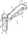
图2是可与图1所示的系统相关联地使用以治疗上胃肠道中的组织的一种类型的治疗装置的去除了一部分的透视图,该治疗装置具有示出为处于皱缩状态中的用于接触组织的操作元件。2 is a perspective view with a portion removed of one type of treatment device that may be used in association with the system shown in FIG. 1 to treat tissue in the upper gastrointestinal tract, with the treatment device shown in a collapsed state. operating elements for contacting tissue.
图3是图2所示的装置的去除了一部分的透视图,该操作元件示出为处于扩展状态中。Figure 3 is a perspective view with a portion removed of the device shown in Figure 2, with the operating element shown in an expanded state.
图4是图2所示的装置的去除了一部分的透视图,该操作元件示出为处于扩展状态中并使电极延伸以供使用。Figure 4 is a perspective view with a portion removed of the device shown in Figure 2, with the operative element shown in an expanded state and extending the electrodes for use.
图5是可通过在食管中在食管下括约肌处或其附近以及在胃的贲门中操纵图2至图4所示的装置而形成的损伤模式,该损伤模式包括多个轴向地隔开的损伤层级,每个损伤层级包括多个沿圆周隔开的损伤。Figure 5 is an injury pattern that can be created by manipulation of the device shown in Figures 2 to 4 in the esophagus at or near the lower esophageal Lesion levels, each lesion level comprising a plurality of circumferentially spaced lesions.
图6是可与图1所示的系统相关联地使用以治疗下胃肠道中的组织的另一种类型的治疗装置的透视图,该治疗装置具有示出为处于缩回位置中的一排电极。6 is a perspective view of another type of treatment device that may be used in association with the system shown in FIG. 1 to treat tissue in the lower gastrointestinal tract, the treatment device having a row of electrode.
图7是图6所示的装置的透视图,这排电极示出为处于其延伸位置中。Figure 7 is a perspective view of the device shown in Figure 6, with the row of electrodes shown in their extended position.
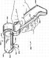
图8是图6和图7所示的装置的透视图,这排电极示出为处于其在下胃肠道中展开以治疗肛管的括约肌机能障碍的延伸位置中。8 is a perspective view of the device shown in FIGS. 6 and 7 with the array of electrodes shown in its extended position deployed in the lower gastrointestinal tract to treat sphincter dysfunction of the anal canal.
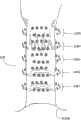
图9是可通过在肛管中在肛门括约肌处或其附近操纵图8所示的装置而形成的损伤模式,该损伤模式包括多个轴向地隔开的损伤层级,每个损伤层级包括多个沿圆周隔开的损伤。Figure 9 is a lesion pattern that may be created by manipulation of the device shown in Figure 8 in the anal canal at or near the anal sphincter, the lesion pattern comprising a plurality of axially spaced lesion levels, each lesion level comprising multiple lesions spaced along the circumference.
图10A和图10B分别是包含图1所示的系统的特征并可与图2或图6所示的治疗装置相关联地使用以治疗身体括约肌和邻接组织区域的集成装置的一个实施方式的左透视图和右透视图,该集成装置还具有这样的控制器:图形用户显示在视觉上以逐步的方式提示用户使用治疗装置执行如同图5或图9所示的在身体区域中形成损伤模式的过程,引导用户完全形成在给定层级内期望的各个损伤,并不遗漏给定层级的损伤。FIGS. 10A and 10B are, respectively, left side views of one embodiment of an integrated device incorporating features of the system shown in FIG. 1 and that may be used in association with the treatment device shown in FIG. 2 or FIG. perspective view and right perspective view, the integrated device also has such a controller: the graphical user display visually prompts the user in a step-by-step manner to use the treatment device to perform the process of forming a lesion pattern in a body region as shown in Figure 5 or Figure 9 The process guides the user to fully form each lesion expected within a given level, and does not omit the lesion of the given level.
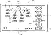
图11是由控制器产生的代表性图形用户设置显示,该控制器在治疗过程之前通过设置和连接步骤用数字和/或文本和/或图标提示用户。Figure 11 is a representative graphical user setup display generated by a controller that prompts the user with numbers and/or text and/or icons through setup and connection steps prior to a treatment procedure.
图12是在识别如同图2至图4所示的装置的连接(通过商标
图13是在识别如同图6至图8所示的装置的连接(通过商标识别)时由控制器产生的代表性图形用户设置显示。Figure 13 is a diagram identifying the connections of devices as shown in Figures 6 to 8 (by trademark Recognized) by the controller to generate a representative graphical user setting display.
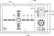
图14A至图14O是由控制器产生的用于在视觉上以逐步的方式提示用户使用如同图2至图4所示的治疗装置执行如同图5所示的在食管中形成损伤模式的过程的代表性图形用户治疗显示,该图形用户显示引导用户并产生从开始到结束的过程的进展的直观记录,以完全形成在给定层级内期望的各个损伤,并不遗漏给定层级的损伤。Figures 14A to 14O are generated by the controller to visually prompt the user in a step-by-step manner to perform the process of forming a lesion pattern in the esophagus as shown in Figure 5 using the treatment device as shown in Figures 2 to 4 A representative graphical user treatment display that guides the user and produces a visual record of the progress of the procedure from start to finish to fully develop each lesion desired within a given level without missing any lesions of the given level.
图15A至图15I是由控制器产生的用于在视觉上以逐步的方式提示用户使用如同图6至图8所示的治疗装置执行如同图9所示的在肛管中形成损伤模式的过程的代表性图形用户治疗显示,该图形用户显示引导用户并产生从开始到结束的过程的进展的直观记录,以完全形成在给定层级内期望的各个损伤,并不遗漏给定层级的损伤。15A to 15I are generated by the controller to visually prompt the user in a step-by-step manner to perform the process of forming a lesion pattern in the anal canal as shown in FIG. 9 using the treatment device as shown in FIGS. 6 to 8 A representative graphical user treatment display of , which guides the user and produces a visual record of the progress of the procedure from start to finish, to fully form the individual lesions expected within a given level, without missing any lesions of the given level.
在不背离其实质或本质特性的前提下,本发明可以几种形式体现。本发明的范围在所附权利要求中限定,而非在权利要求之前的特定描述中限定。因此,落入权利要求的等同物的含义和范围内的所有实施方式都旨在被权利要求涵盖。The present invention may be embodied in several forms without departing from its essence or essential characteristics. The scope of the invention is defined in the appended claims rather than in the specific description preceding the claims. Accordingly, all embodiments that come within the meaning and range of equivalency of the claims are intended to be covered by the claims.
具体实施方式Detailed ways
本说明书公开了各种用于治疗体内的括约肌和邻接组织区域的机能障碍的系统和方法。该系统和方法特别适合于治疗上胃肠道和下胃肠道中的这些机能障碍,例如影响食管下括约肌和邻近的胃的贲门的胃食管反流病(GERD),或影响肛管的内括约肌和外括约肌的大便失禁。为此,将在此上下文中描述该系统和方法。还应理解,所公开的系统和方法可适合于用来治疗体内其他地方的其他机能障碍、以及未必与括约肌相关的机能障碍。例如,本发明的各种方面可用在需要治疗痔疮或小便失禁的过程中,或用在恢复顺应性或以其他方式使内部组织或肌肉区域张紧的过程中。体现本发明的特征的系统和方法还可适合于与基于导管的和未必基于导管的系统和外科技术一起使用。The present specification discloses various systems and methods for treating dysfunction of sphincter muscles and adjacent tissue regions in the body. The system and method are particularly suitable for treating such disorders in the upper and lower gastrointestinal tracts, such as gastroesophageal reflux disease (GERD) affecting the lower esophageal sphincter and the adjacent cardia of the stomach, or the internal sphincter affecting the anal canal and fecal incontinence of the external sphincter. To that end, the system and method will be described in this context. It should also be understood that the disclosed systems and methods may be adapted to treat other dysfunctions elsewhere in the body, and dysfunctions not necessarily related to the sphincter. For example, various aspects of the invention may be used in procedures where it is desired to treat hemorrhoids or urinary incontinence, or to restore compliance or otherwise tension internal tissue or muscle areas. Systems and methods embodying features of the present invention may also be adapted for use with catheter-based and not necessarily catheter-based systems and surgical techniques.
I.系统概述I. System overview
图1示出了用于诊断和/或治疗身体的不同区域中的括约肌和邻接组织的机能障碍的统一标准系统24。在所示实施方式中,将系统24构造为,诊断并治疗体内的至少两个不同的括约肌区域中的机能障碍。Figure 1 shows a uniform
目标括约肌区域可改变。在所示实施方式中,一个区域包括上胃肠道,例如食管下括约肌和邻近的胃的贲门。第二区域包括下胃肠道,例如位于肠、直肠和肛管中的。The targeted sphincter area can vary. In the illustrated embodiment, one region includes the upper gastrointestinal tract, such as the lower esophageal sphincter and the adjacent cardia of the stomach. The second region includes the lower gastrointestinal tract, such as those located in the bowel, rectum, and anal canal.
系统24包括一类(a family of)治疗装置26a和26b。每个装置26a和26b可根据旨在治疗的特定括约肌区域的生理学和解剖学而特别地构造。将在后面为了说明的目的而总体上描述每个装置26a和26b的结构的细节,但是对于本发明来说并不重要。
每个装置26a/26b携带操作元件36a和36b。操作元件36a和36b可根据旨在治疗的特定括约肌区域的生理学和解剖学而不同地构造。尽管如此,如果两个治疗区域的解剖学和生理学相同或足够相似,那么操作元件36a和36b的结构可以是相同或基本相同的。Each
在所示实施方式中,操作元件36a和36b在系统10中用来以选择性的方式对目标括约肌区域中或附近的组织施加能量。所施加的能量在目标区域的表面下方产生一个或多个损伤、或指定的损伤模式。希望表面损伤以保持和保护表面不受热损伤的方式形成。In the illustrated embodiment,
表面损伤的自然康复导致目标组织的生理张紧。表面损伤还会导致异常电路径的中断,这可能导致自发括约肌松弛。无论如何,该治疗可恢复括约肌区域18的正常闭合功能。Natural healing of superficial damage results in physiological tension of the target tissue. Superficial damage can also lead to disruption of abnormal electrical pathways, which can lead to spontaneous sphincter relaxation. Regardless, the treatment restores normal closure of the sphincter region 18 .
系统24包括对所选的以供使用的装置26a/26b的操作元件36a/36b供应治疗能量的发生器38。在所示实施方式中,发生器38供应射频能量,例如具有在大约400kHz至大约10mHz的范围内的频率。当然,可施加其他形式的能量,例如相干光或非相干光;加热或冷却的流体;电阻加热;微波;超声波;组织消融流体;或低温流体。The
所选的装置26a/26b可经由电缆10各自接合至发生器38,以将所产生的能量传送至相应的操作元件36a/36b。
系统24优选地还包括某些辅助处理设备。在所示实施方式中,处理设备包括外部流体输送设备44和外部吸入设备46。
所选的装置26a/26b可经由管道12连接至流体输送设备44,以传送处理流体,从而通过操作元件36a/36b排出或在其附近排出。所选的装置26a/26b还可经由管道14连接至吸入设备46,以从操作元件36a/36b或从其附近传送吸入的物质,从而排出。
系统24还包括控制器52。优选地包括中央处理器(CPU)的控制器52连接至发生器38、流体输送设备44、以及吸入设备46。或者,吸入设备46可包括典型地存在于医生的房间中的传统真空源,该真空源与控制器52无关地连续工作。
控制器52控制功率电平、周期、以及将射频能量分配给特定操作元件36a/36b的持续时间,以获得并保持适合于实现期望的治疗目的的功率电平。相协作地,还期望控制器52控制处理流体的输送,如果希望的话,控制吸入的物质的去除。
控制器52包括输入/输出(I/O)装置54。I/O装置54允许医生输入控制和处理变量,以使得控制器能够产生适当的命令信号。I/O装置54还从与操作元件(如将在后面描述的)相关的一个或多个传感器接收实时处理反馈信息,以由控制器52处理,例如,以控制能量的施加和处理流体的输送。
I/O装置54还包括通过图形向医生呈现处理信息以供查看或分析的图形用户界面(GUI)。将在后面提供与GUI相关的进一步细节。The I/
II.治疗装置II. Treatment device
操作元件36的结构可改变。将描述各种示例性实施方式。The configuration of the operating
A.用于上胃肠道的治疗A. For the treatment of upper gastrointestinal tract
图2至图4示出了用于治疗上胃肠道中的括约肌区域(更特别地是食管下括约肌和邻接的胃的贲门以治疗GERD)的基于导管的装置26a。在所示实施方式中,装置26a包括在其近端处承载有把手28的柔性导管30。导管30的远端承载操作元件36a。2-4 illustrate a catheter-based
在所示实施方式中,操作元件36a包括三维篮状物(basket)56。篮状物56包括一个或多个脊(spine)58,并典型地包括从四个到八个脊58,所述脊通过远端毂60和近端基座62组装在一起。在所示实施方式中,示出了沿圆周以90度间隔隔开的四个脊58。In the illustrated embodiment, the operating
在所示实施方式中,包括气囊的可扩展结构72位于篮状物56内。气囊结构72可由例如聚对苯二甲酸乙二醇酯(PET)材料制成,或由聚酰胺(不柔软的)材料制成,或由辐射交联聚乙烯(半柔软的)材料制成,或由乳胶材料制成,或由硅酮材料制成,或由C-Flex(高度柔软的)材料制成。In the illustrated embodiment, the
气囊结构72呈现在正常情况下通常皱缩(collapse)的状态,如图2所示。在此状态中,篮状物56在正常情况下还皱缩在气囊结构72周围,呈现低轮廓以在食管中展开。The
导管30包括与气囊结构72的内部连通的内腔。配件76(例如注射器起动的止回阀)由把手28承载。配件76与内腔连通。配件76使内腔与注射器78接合(见图3)。注射器78将流体在压力下通过内腔注射至气囊结构72中,导致气囊结构扩展。
气囊结构72的扩展迫使篮状物56打开和扩展(见图3)。当扩展时,由气囊结构72施加的力足以在篮状物56周围的组织上施加展开或扩张力(见图3)。Expansion of the
每个脊58承载电极66(见图4)。因此,具有沿圆周以90度间隔隔开的四个电极。在所示实施方式中,将每个电极66承载在管状脊58内,以进行滑动运动。每个电极66从缩回到脊58中的收回位置(图3所示)和通过脊58中的孔从脊58向外延伸的延伸位置(见图4)滑动。通过一个或多个内部电线使把手28上的推拉杆68与滑动电极66接合。杆68控制电极在收回位置(通过在杆68上向后拉)和延伸位置(通过在杆68上向前推)之间的运动。Each
当延伸时,电极66具有足以在食管下括约肌18或胃16的贲门的平滑肌的组织中刺入期望的深度(见图32)的远端锐度和强度。期望的深度可以在大约4mm到大约5mm的范围。When extended, the
电极66由传导射频能量的材料形成,例如由镍钛、不锈钢(例如304不锈钢)、或镍钛和不锈钢的组合形成。
在所示实施方式中(见图4),将电绝缘材料70涂覆在每个电极66的近端周围。当刺入食管括约肌18或贲门20的平滑肌的电极66的远端传送射频能量时,材料70阻止食管10或贲门20的粘膜表面直接暴露于射频能量。从而避免对粘膜表面的热损伤。在施加射频能量的过程中,粘膜表面还可主动地冷却,以进一步保护粘膜表面不受热损伤。In the illustrated embodiment (see FIG. 4 ), an electrically insulating
在所示实施方式中(见图4),至少一个温度传感器80与每个电极相关联。一个温度传感器80感测电极66的暴露的远端附近的温度情况,第二温度传感器80位于相应的脊58上,当使气囊结构72充气时,所述脊58抵靠在粘膜表面上。In the illustrated embodiment (see FIG. 4 ), at least one
外部流体输送设备44经由管道12(见图1)与连接器48(见图4)接合,以对目标组织供应冷却液体,例如通过脊中的孔。外部吸入设备46经由管道14(见图1)与连接器50(见图4)接合,以从目标组织位置传送液体,例如通过脊中的其他孔或篮状物56上的其他地方。控制器52可控制处理流体的输送,如果希望的话,可控制吸入的物质的去除。External
控制器52可调节电极66以单极模式工作。在此模式中,每个电极66用作能量的发射器,并且,中性膜片电极(indifferent patch electrode)(在后面描述)用作所有电极66的共同回路。或者,控制器52可调节电极66以双极模式工作。在此模式中,一个电极包括发射器,另一电极包括所发射的能量的回路。双极电极对可以是邻接脊上的电极66,或在不同脊上更宽地隔开的电极66。
在使用中,操纵装置26a以产生包括位于几个轴向地隔开的层级(大约隔开5mm)处的损伤的圆周环的多个损伤的优选模式,每个层级包括8个到12个损伤。在图5中示出了损伤模式的示例性实施方式。如图5所示,这些环优选地形成在位于胃上方的区域中的食管中,或形成在食管下括约肌处或其附近,和/或形成在胃的贲门中。贲门中的环围绕贲门的开口漏斗同心地隔开。这些环在食管下括约肌处或其附近沿着食管轴向地隔开。In use, the
伴随着导管的用于重新定位篮状物56的旋转和/或轴向运动,可通过电极66的连续延伸和收回来产生多个损伤模式。医生可通过在目标治疗位置处使气囊结构72扩展并使电极66延伸来产生给定的环模式,以形成第一组的四个损伤。然后,医生可使电极66缩回,使气囊结构72皱缩,并使导管30旋转期望的量,例如30度或45度,取决于在360度内期望的总损伤的数量。然后,医生可再次使结构72扩展并再次使电极66延伸,以实现第二组的四个损伤。医生重复此顺序,直到在环的360度范围内形成期望数量的损伤为止。可通过使操作元件轴向地前进、用导管上的外部标记计量环间隔来产生位于不同的层级处的额外的损伤。Multiple injury modes may be created by the successive extension and retraction of the
如图5所示,期望的模式包括在下标方向上编号为层级1至层级6的六个圆周损伤的轴向隔开的模式,一些层位于胃的贲门中,其他层在胃上方的食管中位于食管下括约肌处或其附近。在当前考虑的图5中示出的实施方式中,在层级1、2、3和4中,具有沿圆周隔开45度的8个损伤(即,第一能量施加,然后是篮状物56的45度旋转,然后是第二能量施加)。在层级5和6中,具有沿圆周隔开30度的12个损伤(即,第一能量施加,然后是篮状物56的30度旋转,然后是第二能量施加,然后是篮状物56的30度旋转,然后是第三能量施加)。在层级5中,仅使气囊结构72部分地扩展,而在层级6中,使气囊结构72更完全地扩展,以根据贲门漏斗中可用的漏斗形状的空间提供周长增加的损伤模式。As shown in Figure 5, the desired pattern consists of an axially spaced pattern of six circumferential lesions numbered
B.用于下胃肠道的治疗B. For the treatment of lower gastrointestinal tract
图6和图7示出了装置26b的示例性实施方式,该装置具有用于治疗下胃肠道中的括约肌区域(更特别地是肛管中的内括约肌和/或外括约肌以治疗大便失禁)的用手操纵的装置302的形式。装置302包括承载操作元件36b的手柄304。Figures 6 and 7 illustrate an exemplary embodiment of a
在所示实施方式中,操作元件36b具有由透明的模塑塑性材料制成的空心管状圆筒306的形式。圆筒306终止于钝的倒圆远端308,以帮助圆筒306通过肛管,不需要单独的导入器。手柄304包括用于查看圆筒306的透明空心内部的观察口312,以使得能够看见周围的组织。In the embodiment shown, the
沿着圆筒306的弓形段以并排的关系可移动地装有一排针电极316。在所示实施方式中,针电极316在圆筒306上占据大约67.5度的圆弧。针电极316与手柄304上的用手指操作的拉杆318机械地连接。通过拉杆318的操作,使针电极316的远端在缩回位置(图5)和延伸位置(’523专利的图6)之间移动。除了在此对组织施加射频能量的远端的指定区域以外,在针电极316周围涂覆电绝缘材料344(见’523专利的图6)。发生器38经由电缆10与连接器352接合,以对电极316传送射频能量。A row of
在使用中(见图8),医生抓握手柄304并将圆筒306引导到肛管320中。拉杆318处于中立位置而没有被按下,因此,针电极316占据其正常缩回位置。通过观察口312观察,医生能够看见通过圆筒306的梳状(齿状)线。通过圆筒306观察,医生将针电极316的远端相对于梳状(齿状)线定位在期望的位置处。光纤也可位于圆筒306中以提供局部照明。一旦圆筒306的远端位于目标位置处,医生便按下拉杆318(如图8所示)。针电极316前进至其延伸位置。电极316的远端刺穿并通过粘膜组织进入目标括约肌的肌肉组织中。在图8中,将电极316的远端示出为刺入不随意内括约肌322。医生指挥控制器52通过针电极316施加射频能量。该能量可由所有电极316同时施加,或以任何期望的顺序施加。In use (see FIG. 8 ), the physician grasps the
外部流体输送设备44经由管道12与连接器348接合,以传送冷却液,例如通过圆筒306中的孔,从而接触位于电极316周围的局部位置处的组织。外部吸入设备46经由管道14与连接器350接合,以从目标组织位置传送液体,例如通过位于圆筒306(见图6和图7)的远端308中的吸入口358。External
圆筒306(见图7)还优选地承载温度传感器364,其中一个温度传感器与每个针电极316相关联。传感器364感测每个针电极316附近的区域中的组织温度情况。优选地,每个针电极316的远端还承载温度传感器372(见图7)。The barrel 306 (see FIG. 7 ) also preferably carries temperature sensors 364 , one associated with each
在使用中(见图9),多个损伤的优选模式形成为包括处于几个轴向地隔开的层级(大约隔开5mm)中的损伤的圆周环,每个环包括处于四个四分之一圆(quadrant)中的16个损伤,每4个损伤处于一个四分之一圆中。这些环在齿状线处或其附近沿着肛管轴向地形成。In use (see Figure 9), the preferred pattern of multiple lesions is formed as a circumferential ring comprising lesions in several axially spaced levels (approximately 5 mm apart), each ring comprising 16 lesions in a quadrant, with every 4 lesions in a quadrant. These rings form axially along the anal canal at or near the dentate line.
流体输送设备68传送冷却液以在治疗位置处排出,从而在由针电极316施加能量的同时使粘膜表面冷却。吸入设备76通过管道78吸取吸入的物质和处理流体以排出。
参考图9,将这排针电极316定位在层级1处,以在第一四分之一圆中产生4个多样的损伤。如刚刚描述的,当在层级1的第一四分之一圆中令人满意地产生损伤模式时,医生起动按钮64以从棘爪掣62释放锁定棘爪58。拉杆52回到弹簧加载的中立位置,从而使针电极316移回至其缩回位置。仍抓握手柄40并通过观察口46观察,医生使圆筒轴向地向上移动5mm至层级2,第一四分之一圆。医生再次展开针电极48并执行另一损伤产生顺序。医生重复步骤的此顺序,直到在层级1、2、3、4和5中的轴向地隔开的第一四分之一圆内形成额外数量的损伤模式为止。Referring to Figure 9, the row of
仍抓握手柄40并通过观察口46观察,医生回到层级1,并使圆筒42在第一损伤模式94的层级处旋转所选的弧形距离而达到第二四分之一圆,即,通过使圆筒42旋转90度。Still grasping the handle 40 and looking through the
医生再次展开针电极48并在层级1的四分之一圆2处执行另一损伤产生顺序。然后,医生在大体与损伤模式96,98和100一致的许多轴向地隔开的层级2,3,4和5处使圆筒轴向地向上移动5mm的增量。这样在层级1,2,3,4和5的第二四分之一圆中形成损伤。The physician again deploys the
医生将上述顺序额外重复两次,使圆筒回到层级1,以连续的间隔旋转圆筒42并轴向地重新定位圆筒42,以在层级1,2,3,4和5中形成损伤模式四分之一圆3和4。此方案形成混合损伤模式102,其在目标括约肌组织区域中提供密集的损伤,以激发括约肌组织的期望的收缩。The physician repeats the above sequence two additional times, returning the cylinder to
III.系统操作III. System Operation
在所示实施方式中(见图10A和图10B),将射频发生器38、具有I/O装置54的控制器52、以及流体输送设备44(例如用于输送冷却液)集成在单个壳体400内。In the illustrated embodiment (see FIGS. 10A and 10B ), a
I/O装置54将控制器52与显示微处理器474接合(见图10A)。显示微处理器474在壳体400中与图形显示监控器420接合。控制器52通过显示微处理器474执行图形用户界面,或GUI,所述图形用户界面显示在显示监控器420上。所述图形用户界面可通过使用MS
A.设置A. Settings
在启动CPU时(见图11),操作系统对GUI 500执行设置功能。GUI显示适当的启动标识和名称图像(未示出),同时控制器52执行自检。一排设置提示502引导操作员以逐步的方式完成使得能够使用发生器和装置所需的任务。医生可使冷却液体源与装置26a/26b(见图10A,如之前所描述的)的把手上的适当端口接合,并将从冷却液体源(例如装有无菌水的袋子)开始的管道装入泵转子428(见图10B)中。医生还可使吸入源46与治疗装置26a/26b(同样如已经描述的)的把手上的适当端口接合。医生还可使膜片电极412与脚踏开关416(图10A所示)接合。在这排设置提示502中,GUI 500的图形区域显示一个或多个图标和/或字母数字的标记502,这些标记提示操作员连接回路膜片电极412、连接脚踏开关或开关416、连接所选的治疗装置26a(由其商标

控制器52通过读取位于装置26a或26b的把手中的编码识别元件,来确定已经选择以供使用的装置26a或26b。在此输入的基础上,控制器52继续对与发生器接合的特定装置26a和26b执行预编程的控制和图形GUI命令功能。The
如果登记的是用于装置26a的识别码

B.治疗屏幕(UGUI和LGUI)B. Treatment screens (UGUI and LGUI)
在完成设置操作时,控制器52继续调节发生器和辅助设备,以逐步地继续通过一系列操作模式。已将操作模式预编程为实现所选的装置26a/26b的治疗方案和目的。这些操作模式的进行和在所选的步骤的进行过程中引导并告诉用户的图形用户界面的外观在装置26a和26b之间可以是不同的。Upon completion of the setup operation, the
为了便于描述,GUI 500对于上胃肠过程(即对于装置26a)显示通常将简称为UGUI 504(图14A)的治疗屏幕。同样地,GUI对于下胃肠过程(即对于装置26b)显示通常将简称为LGUI 506(图15A)的治疗屏幕。For ease of description,
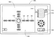
在UGUI 504(图14A)和LGUI 506(图15A)中,具有标明冷却流体流速/起动注水(priming)的参数图标462。在UGUI 504和LGUI 506中,流速/起动注水图标462用条的数量显示出所选的泵速,照亮一个条表示低速,照亮两个条表示中速,照亮三个条表示高速。In UGUI 504 (FIG. 14A) and LGUI 506 (FIG. 15A), there is a
每个UGUI 504(图14A)和LGUI 506(图15A)包括电极图标466。通常,每个电极图标466包括理想化的图形图像,所述图形图像在空间上模仿已与控制器42接合的治疗装置26a/26b的特定多电极几何形状。正如装置26a和26b的多电极几何形状不同一样,因此,UGUI 504的电极图标466与LGUI 506的电极图标466也不同。Each UGUI 504 ( FIG. 14A ) and LGUI 506 ( FIG. 15A ) includes an
如图14A所示,在UGUI 504中,在图标466的图形图像中示出了间隔90度的四个电极。此图形图像反映了装置26a的四电极结构的几何形状,如图4所示。As shown in Figure 14A, in
如图15A所示,在LGUI 506中,在图标466的图形图像中示出了沿着部分弧形区域处于沿圆周隔开的关系的四个电极。此图形图像反映了治疗装置26b上的电极的布置,如图7所示。As shown in FIG. 15A , in
对于每个电极,相应的图标466在空间显示中包含图形区域O1、O2和O3。区域O1和O2显示该电极所遇到的温度情况。区域O1用数字显示在UGUI 504(图14A)和LGUI 506(图15A)中感测到的电极头温度的大小。区域O2用数字显示对于UGUI 504(图14A)和LGUI 506(图15A)中的该电极感测到的组织温度。区域O3显示对于每个电极得到的阻抗值。UGUI 504和LGUI 506都显示来自头电极和组织表面的瞬时感测到的温度读数、以及与区域O1、O2和O3中的电极成空间关系地连续显示的阻抗值。For each electrode, the
对于给定的电极,如果相应的电极/通道已禁用,那么可由医生或由感测到的出界情况取消区域O1/O2/O3的数字显示。还可在区域O1/O2/O3的背景中显示“可接受”颜色指示(例如绿色),只要感测到的情况处于期望的预建立的范围内。然而,如果感测到的情况落在期望的范围之外,那么该颜色指示变成“不期望”颜色指示(例如变成灰色),并取消数字显示。For a given electrode, the digital display of zones O1/O2/O3 can be canceled by the physician or by a sensed out-of-bounds condition if the corresponding electrode/channel is disabled. An "acceptable" color indication (eg green) may also be displayed in the background of the area O1/O2/O3 as long as the sensed condition is within the desired pre-established range. However, if the sensed condition falls outside the desired range, then the color indication changes to an "undesired" color indication (eg, gray), and the digital display is canceled.
在每次显示UGUI 504和LGUI 506中,在相应的电极图标466附近,还具有损伤层级图标510。损伤层级图标510包括理想化的图形图像,所述图形图像在空间上模仿期望的损伤层级和每个层级中的损伤的数量。正如装置26a和26b产生的损伤模式不同一样,因此,UGUI 504的损伤层级图标510与LGUI 506的电极图标466也不同。In each display of
如后面将更详细地描述的,损伤层级图标510实时地改变,以逐步地引导医生完成步骤并记录从开始到结束的过程的进展。在许多基本方面中,用于LGUI 504和LGUI 506的损伤层级图标510的外观和感觉是相似的,但是由于损伤形成的方案的差异它们在植入细节上是不同的。As will be described in more detail later, the
现在将描述用于UGUI 504和LGUI 506的损伤层级图标510的示例性变化。Exemplary variations of
1.UGUI1. UGUI
在UGUI 504中(见图14A),显示了6个编号的损伤层级1,2,3,4,5和6,以与在图5中已经描述和示出的损伤层级相对应。UGUI 504还显示了波浪线514,所述波浪线标记出在此医生已经看见用于在食管内形成损伤以供治疗的所选的解剖基部参考。由UGUI 504引导,相对于此解剖基部设置损伤。In UGUI 504 (see FIG. 14A ), six numbered
为治疗做准备,医生使得在食管中能够看见间线(z-line)或其他期望的解剖界标。沿着导管以5mm的间隔布置标记。当能够看见间线时,医生在与此位置相对应的导管上记下外部标记。参考该标记,然后,医生可使导管轴向地前进或缩回与损伤层级之间的期望间隔相对应的5mm的增量。在图5中也示出了损伤层级的这种定向。In preparation for treatment, the physician enables visualization of the z-line or other desired anatomical landmarks in the esophagus. Markers were placed at 5 mm intervals along the catheter. When the line is visible, the doctor notes an external marker on the catheter that corresponds to this location. Referring to this marker, the physician can then axially advance or retract the catheter in 5mm increments corresponding to the desired separation between lesion levels. This orientation of the lesion levels is also shown in FIG. 5 .
UGUI 504通过图形确定损伤层级4,5和6的位置相对于此解剖基部的方向,显示位于波浪线514下方(低于波浪线)的损伤层级(损伤层级4,5和6)或位于波浪线514处或位于波浪线上方的损伤层级(损伤层级1,2和3)。The
如将描述的,根据相应层级内的损伤形成的状态,UGUI 504通过图形改变损伤层级的显示。As will be described,
图14A示出了给定损伤层级的代表性第一图形形式。该图形形式包括,例如,UGUI 504上的扁立圆柱体,如在图14A中对于损伤层级1至6所示。一目了然,该图形形式表示在相应损伤层级中不存在损伤。Figure 14A shows a representative first graphical form for a given lesion level. The graphical form includes, for example, an oblate cylinder on the
如图14A所示,紧挨着损伤层级1的扁立圆柱体(edgewise cylinder)的图形形式的是引导标记512。引导标记512表示首先将表示损伤层级1中的损伤的形成。与损伤层级1的扁立圆柱体相关联地显示数值(15mm),其表示损伤层级1距离解剖界标15mm。位于波浪线514上方(高于波浪形)的损伤层级1的定向引导医生使导管从解剖标记向上前进15mm,以将导管放置在损伤层级1处。气囊图标516提示医生在损伤层级1处使装置26a的篮状物扩展。As shown in FIG. 14A , next to the graphic form of the edgewise cylinder of
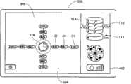
当感测电极阻抗时,表示与损伤层级1处的组织相接触(或响应表示在期望损伤层级处的装置26a的展开的另一输入),控制器命令UGUI 504将损伤层级1的图形形式变成图14B所示的第二图形形式。第二图形形式(图14B所示)与第一图形形式(图14A所示)不同。该图形形式包括,例如,分段圆,紧挨着该分段圆具有数字指示。这在图14B中对于损伤层级1示出。在视觉效果上,第二图形形式示出了沿着其轴线旋转以供观察的之前的圆柱体形式。所示区段的数量(在图14B中,具有8个区段)与将在损伤层级1处形成的损伤的数量相对应。When electrode impedance is sensed, indicating contact with tissue at Lesion Level 1 (or in response to another input indicating deployment of
在图14B中,圆的所有区段都没有标记。一目了然,该图形形式表示:(i)现在表示在该损伤层级处形成损伤(由于损伤层级图标的轴向圆形视图);(ii)将形成沿圆周隔开的8个损伤(由于区段的数量);(iii)尚未形成损伤(由于在区段中没有其他标记)。In Figure 14B, all segments of the circle are unmarked. At a glance, this graphical form indicates that: (i) now indicates that a lesion is formed at this lesion level (due to the axial circular view of the lesion level icon); (ii) 8 lesions spaced along the circumference will be formed (due to the number); (iii) lesions have not yet formed (due to lack of other markers in the segment).
还改变标记512的位置,以与损伤层级2对准,具有5mm的数字指示。这告诉医生:在损伤层级1后,下一待治疗的损伤层级是位于损伤层级1下方(低于该损伤层级)5mm的损伤层级2。The position of the
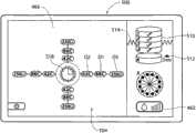
通过定位在损伤层级1处的装置26a,医生在第一预置周期内起动电极。当在给定层级上继续治疗时,气囊图标516消失。定时器图标518表示在预置周期内施加射频能量。在此预置周期结束时(见图14C),治疗标记(例如圆点)出现在图形分段圆的四个区段中,表示第一四个损伤的形成、及其空间定向。With
分段圆中剩余的没有治疗标记的区段提示医生将篮状物旋转45度,并第二次起动电极。在预置周期(通过定时器图标518跟踪)后(见图14D),更多的治疗标记(圆点)出现在圆的剩余区段中。这表示,已经形成为损伤层级1指定的所有损伤,使篮状物收缩并移动至下一治疗层级。所显示的标记512将医生引导至位于损伤层级1下方5mm的损伤层级2。气囊图标516可重新出现,以提示医生使气囊收缩。The remaining unmarked segments in the segmented circle prompt the physician to rotate the basket 45 degrees and activate the electrodes a second time. After a preset period (tracked by timer icon 518) (see FIG. 14D), more treatment indicia (dots) appear in the remaining segment of the circle. This means that all lesions designated for
从而,提示医生使篮状物收缩,移动至损伤层级2,并使篮状物扩展。如图14E所示,当感测电极阻抗时,表示与损伤层级2处的组织相接触,UGUI 504将损伤层级1的图形形式变回至扁立圆柱体。用于损伤层级1的扁立圆柱体包括一指示,例如勾号(checkmark),以表示已经治疗损伤层级1(如图14E所示)。治疗完成指示的插入是UGUI 504显示以向医生传达状态信息的又一图形形式。Thus, the physician is prompted to retract the basket, move to
还参考图14E,当感测电极阻抗时,表示与损伤层级2处的组织相接触,UGUI 504将损伤层级2的图形形式变成第二图形形式,包括,例如已经描述的分段圆。这在图14E中对于损伤层级2示出。还改变标记512的位置,以与损伤层级3对准,具有5mm的数字指示。这告诉医生:在损伤2后,下一损伤层级将是位于损伤层级2下方(低于该损伤层级)5mm的损伤层级3。Referring also to FIG. 14E , when electrode impedance is sensed, indicating contact with tissue at
如图14F和图14G所示,通过定位在损伤层级2处的装置26a,医生在第一预置周期内起动电极,然后将装置26a旋转45度,并在第二预置周期内起动电极。定时器图标518反映在预置周期内施加射频能量,并对图形分段圆的区段增加治疗标记(例如圆点),表示第一四个损伤(图14F)和下一四个损伤(图14G)的形成、及其空间定向。As shown in Figures 14F and 14G, with
当在损伤层级2中形成8个损伤时,气囊图标518再次出现。这表示,已经形成为损伤层级2指定的所有损伤,使篮状物收缩并移动至下一治疗层级。所显示的标记512将医生引导至位于损伤层级2下方5mm的损伤层级3。When 8 lesions are formed in
从而,提示医生使篮状物收缩,移动至损伤层级3,并使篮状物扩展。当感测电极阻抗时,表示与损伤层级3处的组织相接触(见图14H),UGUI504将损伤层级2的图形形式变回至扁立圆柱体(如图14H所示)。用于损伤层级2的扁立圆柱体现在包括一指示,例如勾号,以表示已经治疗损伤层级2(也如图14H所示)。Thus, the physician is prompted to retract the basket, move to
还如图14I所示,当感测电极阻抗时,表示与损伤层级3处的组织相接触,UGUI 504将损伤层级3的图形形式变成第二图形形式,包括,例如已经描述的分段圆。这在图14H中对于损伤层级3示出。还改变标记512的位置,以与损伤层级4对准,具有5mm的数字指示。这告诉医生:在损伤3后,下一损伤层级将是位于损伤层级3下方(低于该损伤层级)5mm的损伤层级4。As also shown in FIG. 141 , when electrode impedance is sensed, indicating contact with tissue at
医生继续在损伤层级3中形成8个损伤(图14I和图14J),然后移动至损伤层级4(未示出,但是遵循与已经描述的相同的进程)。UGUI 504始终在视觉上记录并确认进程。如图14K所示,当已在相应的层级上形成期望数量的损伤并已完成该层级的治疗时,用于损伤层级3和4的图形损伤层级圆柱体回到扁立圆柱体。此时,勾号出现在扁立圆柱体上,表示对于损伤层级1,2,3和4已完成该层级处的治疗(如图14K所示)。The doctor proceeds to create 8 lesions in Lesion Level 3 (Figs. 14I and 14J) and then moves to Lesion Level 4 (not shown, but follows the same progression as already described).
如图14K至图14N所示,在损伤层级5和6上,分段圆中的区段共有12个,表示将在这些层级上形成12个损伤。在层级5和6中,具有沿圆周隔开30度的12个损伤(即,第一能量施加,然后是篮状物56的30度旋转,然后是第二能量施加,然后是篮状物56的30度旋转,然后是第三能量施加)。在层级5中,仅使气囊结构部分地扩展,而在层级6中,气囊结构72使更完全地扩展,以根据贲门漏斗中可用的漏斗形状的空间提供周长增加的损伤模式。As shown in FIGS. 14K to 14N , on
UGUI 504反映治疗的完成(见图14O)。
因此,通过有目的地操纵不同的程式化图形图像,UGUI 504在视觉上提示医生逐步地执行形成包括多个轴向地隔开的损伤层级的损伤模式的过程,每个损伤层级包括多个沿圆周隔开的损伤。当在每个沿圆周隔开的层级内及其间实时地产生损伤时,UGUI 504记录损伤的形成。因此,UGUI 504向医生显示从开始到结束的过程的进展的直观记录。UGUI 504确保不遗漏在给定层级内期望的各个损伤,或确保不遗漏给定层级的损伤。Thus, by purposefully manipulating different stylized graphic images, the
在UGUI 508中,每个损伤层级1至6最初由第一程式化图形图像图示,该第一程式化图形图像包括具有其层级的数字识别的扁立圆柱体。当表示在给定层级处形成损伤时,UGUI 504将第一程式化图形图像变成与第一图像不同的第二程式化图形图像,该第二程式化图形图像包括圆柱体的轴向视图,呈现分段圆,具有与将形成的损伤的数量相对应的区段的数量。还与下一将处理的损伤层级(仍显示为扁立圆柱体)并置(juxtapose)地呈现具有表示下一将处理的损伤层级距离当前损伤层级的距离的数字的标记。当医生操纵装置26a以在所指示的层级上形成损伤时,第二图形图像还变成与第一或第二图像不同的第三图形图像,通过在分段圆内增加标记以反映损伤的形成,以引导医生连续地旋转并在损伤层级处操纵装置26a。当在给定层级上形成期望的损伤模式时,UGUI 504再次将第三图形图像变成与第一、第二和第三图形图像不同的第四图形图像,包括具有其层级的数字识别的扁立圆柱体、以及表示已在相应层级处形成所有期望损伤的另一指示(例如勾号)。连续地更新标记512,以将医生引导至下一损伤层级。这样,UGUI 504提示在层级1,2,3和4中形成沿圆周隔开45度的8个损伤,并在层级5和6形成沿圆周隔开30度的12个损伤。In UGUI 508, each
2.LGUI2. LGUI
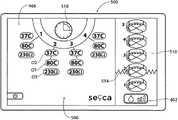
LGUI 506(图15A)产生引导医生操作装置26b以在肛管中形成指定损伤模式的图形用户显示,如图9所示。损伤模式包括轴向地隔开的多个损伤层级(在所示实施方式中,标号为1至5),每个损伤层级包括沿圆周隔开的多个损伤(在所示实施方式中,具有16个损伤,布置为4个一组)。LGUI 506 ( FIG. 15A ) generates a graphical user display that guides the physician in manipulating
LGUI 506(见图15A)的显示示出了与将在肛管中形成的多个损伤层级相应的损伤层级1,2,3,4和5。将损伤层级1至5显示为编号为1至5的分段圆盘,这些分段圆盘在其轴线上稍微倾斜,并一个布置在另一个之上。每个圆盘分成四个四分之一圆。The display of the LGUI 506 (see FIG. 15A ) shows
LGUI 506还示出了(见图15A)齿状波浪线514。为治疗做准备,医生使得在肛管中能够看见齿状线或其他期望的解剖界标。沿着装置26b的圆筒以5mm的间隔布置标记。当能够看见齿状线时,医生在与此位置相对应的圆筒上记下外部标记。参考该标记,然后,医生可使圆筒轴向地前进或缩回与损伤层级之间的间隔相对应的5mm的增量。The
紧挨着损伤层级1的圆盘的图形形式的是引导标记512(见图15A)。引导标记512表示将表示损伤层级1中的损伤的形成。与损伤层级1的扁立圆柱体相关联地显示数值(5mm),其表示损伤层级1距离解剖界标5mm。Next to the graphical form of the
在图15A中,损伤层级圆盘的所有四分之一圆都没有标记。一目了然,该图形形式表示:(i)现在表示在损伤层级1处形成损伤(由于标记512的位置);以及(ii)尚未形成损伤(由于在四分之一圆中没有标记)。In Figure 15A, all quadrants of the lesion level disc are unmarked. At a glance, this graphical form indicates that: (i) a lesion is now formed at lesion level 1 (due to the location of marker 512 ); and (ii) a lesion has not yet been formed (due to the absence of a mark in the quadrant).
装置26b包括以圆弧布置的一排四个针电极,可使这些针电极前进和缩回(见图6)。将这排针电极定位在层级1处,与四分之一圆1对准,并使这些针电极前进。医生在第一预置周期内起动电极。定时器图标518示出了在预置周期内施加射频能量。在此预置周期结束时,治疗标记(例如四个圆点)出现在图形分段圆盘的第一四分之一圆中(见图15B),表示第一四个损伤的形成、及其在第一四分之一圆中的空间定向。
还改变标记512的位置,以与损伤层级2对准,具有5mm的数字指示。这告诉医生:在损伤层级1后,下一个损伤层级将是位于损伤层级1上方(高于该损伤层级)5mm的损伤层级2。The position of the
如刚刚描述的,并如由标记512(现在与损伤层级2对准)所提示的,当在层级1的第一四分之一圆中令人满意地产生损伤模式时,医生起动按钮以使针电极移回至其缩回位置。仍抓握手柄并通过观察口观察,医生使圆筒轴向地向上移动5mm至层级2,保持通过旋转对准在第一四分之一圆中。医生再次使针电极展开并执行另一损伤产生顺序。还改变标记512的位置,以与损伤层级3对准,具有5mm的数字指示。这告诉医生:在损伤层级2后,下一个损伤层级将是位于损伤层级2上方(高于该损伤层级)5mm的损伤层级3。治疗标记(例如四个圆点)出现在损伤层级2的图形分段圆盘的第一四分之一圆中(见图15C),表示形成四个损伤、及其在第一四分之一圆中的空间定向。As just described, and as prompted by marker 512 (now aligned with Lesion Level 2), when the lesion pattern is satisfactorily produced in the first quadrant of
医生重复此步骤的顺序,直到在层级2、3、4和5中的轴向地隔开的第一四分之一圆内形成额外数量的损伤模式为止(见图15D、图15E和图15F)。还改变标记512的位置,以与连续的损伤层级对准,以将医生引导至该损伤层级。治疗标记(例如四个圆点)出现在损伤层级2,3,4和5的图形分段圆盘的第一四分之一圆中(见图15F),表示形成四个损伤、及其在第一四分之一圆中的空间定向。The physician repeats this sequence of steps until an additional number of injury patterns are formed within the first axially spaced quadrants in
当在损伤层级5的四分之一圆1中形成四个损伤时,标记512回到损伤层级1(见图15F),提示医生回到损伤层级1,并再次使圆筒在损伤层级1处旋转所选的弧形距离,以与第二四分之一圆对准,即,通过使圆筒旋转90度。When four lesions are formed in
由LGUI 506引导,医生再次使针电极展开并在层级1的四分之一圆2处执行另一损伤产生顺序。由LGUI 506引导(如图15G所示),并遵循标记512,然后医生使圆筒轴向地向上移动5mm的增量,在损伤层级2的四分之一圆2之后,然后是损伤层级3的四分之一圆2、损伤层级4的四分之一圆2、以及损伤层级5的四分之一圆2。在每个损伤层级处,医生使针电极展开并在相应层级的四分之一圆2处执行另一损伤产生顺序。当在每个损伤层级形成损伤后,治疗标记(例如四个圆点)出现在损伤层级2,3,4和5的图形分段圆盘的第二四分之一圆中(见图15G),表示形成四个损伤、及其在第二四分之一圆中的空间定向。Guided by the
当在损伤层级5的四分之一圆2中形成四个损伤时,标记512回到损伤层级1。医生回到损伤层级1,并再次使圆筒在损伤层级1处旋转所选的弧形距离,以与第三四分之一圆对准,即,通过使圆筒旋转90度。When four lesions are formed in
由LGUI 506引导(见图15H),医生再次使针电极48展开并在层级1的四分之一圆3处执行另一损伤产生顺序。治疗标记(例如四个圆点)出现在损伤层级1的图形分段圆盘的四分之一圆3中,表示形成四个损伤、及其在第三四分之一圆中的空间定向。Guided by the LGUI 506 (see FIG. 15H ), the physician again deploys the
如图15H所示,由LGUI 506引导,并遵循标记512,当该标记随着每个层级处的损伤形成而前进时,然后医生使圆筒轴向地向上移动5mm的增量,在损伤层级2的四分之一圆3之后,然后是损伤层级3的四分之一圆3,然后是损伤层级4的四分之一圆3、以及损伤层级5的四分之一圆3。在每个损伤层级处,医生使针电极展开并在相应层级的四分之一圆3处执行另一损伤产生顺序。治疗标记(例如四个圆点)出现在损伤层级2,3,4和5的图形分段圆盘的第三四分之一圆中(见图15H),表示形成四个损伤、及其在第三四分之一圆中的空间定向。As shown in Figure 15H, guided by the
医生将上述顺序额外重复一次,使圆筒回到损伤层级1,并使圆筒旋转90度以与损伤层级1的四分之一圆4对准(见图15I)。医生在层级1,2,3,4和5中形成损伤模式四分之一圆4。治疗标记(例如四个圆点)出现在损伤层级1,2,3,4和5的图形分段圆盘的第四四分之一圆中(见图15B),表示形成四个损伤、及其在第二四分之一圆中的空间定向。另外,通过在每个损伤层级处在第四四分之一圆中形成损伤,代表损伤层级的每个四分之一圆由四个圆点标记(表示损伤产生的完成)的图形圆盘变成另外包括一指示,例如勾号,以指示已经治疗相应的损伤层级(见图15I)。The physician repeats the above sequence one additional time, returning the cylinder to
如上所述,LGUI 506在视觉上以逐步的形式提示用户执行在肛管中形成损伤模式的过程,该模式包括多个轴向地隔开的损伤层级,每个损伤层级包括多个沿圆周隔开的损伤。当在每个沿圆周隔开的层级内及其间实时地产生损伤时,LGUI 506记录损伤的形成。LGUI 506向用户显示从开始到结束的过程的进展的直观记录,引导用户完全形成在给定层级内期望的各个损伤,并不遗漏给定层级的损伤。As described above, the
LGUI 506的每个损伤层级1至5由第一程式化图形图像图示,该第一程式化图形图像包括具有其层级的数字识别的边缘倾斜的圆盘。与在其中将形成损伤的区域相对应地分割圆盘。还与下一将处理的损伤层级并置地呈现具有表示下一将处理的损伤层级距离当前损伤层级的距离的数字的标记。当医生操纵装置26b以在所指示的层级上形成损伤时,第二图形图像还变成与第一图像不同的第二图形图像,通过在分段圆内增加标记以反映损伤的形成,以引导医生在损伤层级处连续地操作装置。当形成期望的损伤模式时,UGUI 506再次将第二图形图像变成与第一、第二图形图像不同的第三图形图像,该第三图形图像包括表示已在该层级处形成所有期望损伤的指示(例如勾号)。更新标记512,以将医生引导至下一损伤层级。这样,UGUI 506提示在层级1,2,3,4和5中形成沿圆周隔开的每组四个损伤的四组损伤(总共12个损伤)。Each
Claims (7)
Translated fromChinesePriority Applications (1)
| Application Number | Priority Date | Filing Date | Title |
|---|---|---|---|
| CN201510182248.9ACN104905875B (en) | 2009-09-22 | 2010-09-22 | For controlling the system and method for using and operating of a kind of different therapeutic systems |
Applications Claiming Priority (3)
| Application Number | Priority Date | Filing Date | Title |
|---|---|---|---|
| US27726009P | 2009-09-22 | 2009-09-22 | |
| US61/277,260 | 2009-09-22 | ||
| PCT/US2010/002588WO2011037621A2 (en) | 2009-09-22 | 2010-09-22 | Systems and methods for controlling use and operation of a family of different treatment devices |
Related Child Applications (1)
| Application Number | Title | Priority Date | Filing Date |
|---|---|---|---|
| CN201510182248.9ADivisionCN104905875B (en) | 2009-09-22 | 2010-09-22 | For controlling the system and method for using and operating of a kind of different therapeutic systems |
Publications (2)
| Publication Number | Publication Date |
|---|---|
| CN102711642Atrue CN102711642A (en) | 2012-10-03 |
| CN102711642B CN102711642B (en) | 2015-04-29 |
Family
ID=43796423
Family Applications (2)
| Application Number | Title | Priority Date | Filing Date |
|---|---|---|---|
| CN201080052854.4AExpired - Fee RelatedCN102711642B (en) | 2009-09-22 | 2010-09-22 | Systems and methods for controlling the use and operation of a class of disparate therapeutic devices |
| CN201510182248.9AExpired - Fee RelatedCN104905875B (en) | 2009-09-22 | 2010-09-22 | For controlling the system and method for using and operating of a kind of different therapeutic systems |
Family Applications After (1)
| Application Number | Title | Priority Date | Filing Date |
|---|---|---|---|
| CN201510182248.9AExpired - Fee RelatedCN104905875B (en) | 2009-09-22 | 2010-09-22 | For controlling the system and method for using and operating of a kind of different therapeutic systems |
Country Status (5)
| Country | Link |
|---|---|
| US (8) | US20110112529A1 (en) |
| EP (1) | EP2480152B1 (en) |
| JP (2) | JP5764564B2 (en) |
| CN (2) | CN102711642B (en) |
| WO (1) | WO2011037621A2 (en) |
Cited By (2)
| Publication number | Priority date | Publication date | Assignee | Title |
|---|---|---|---|---|
| CN107440787A (en)* | 2016-06-01 | 2017-12-08 | 四川锦江电子科技有限公司 | A kind of basket shape ablation catheter and ablating device |
| CN110678138A (en)* | 2017-03-17 | 2020-01-10 | 埃尼奥·查维斯·德·奥利维拉 | Apparatus, system and method for treating swollen vascular structures |
Families Citing this family (37)
| Publication number | Priority date | Publication date | Assignee | Title |
|---|---|---|---|---|
| US7329254B2 (en) | 1998-02-19 | 2008-02-12 | Curon Medical, Inc. | Systems and methods for treating dysfunctions in the intestines and rectum that adapt to the anatomic form and structure of different individuals |
| US8597290B2 (en)* | 1999-07-14 | 2013-12-03 | Mederi Therapeutics | Method for treating fecal incontinence |
| US8361067B2 (en) | 2002-09-30 | 2013-01-29 | Relievant Medsystems, Inc. | Methods of therapeutically heating a vertebral body to treat back pain |
| US20050288664A1 (en)* | 2004-06-21 | 2005-12-29 | Curon Medical, Inc. | Systems and methods for treating tissue regions of the body |
| US10028753B2 (en) | 2008-09-26 | 2018-07-24 | Relievant Medsystems, Inc. | Spine treatment kits |
| CA2737374C (en) | 2008-09-26 | 2017-03-28 | Relievant Medsystems, Inc. | Systems and methods for navigating an instrument through bone |
| US10386990B2 (en) | 2009-09-22 | 2019-08-20 | Mederi Rf, Llc | Systems and methods for treating tissue with radiofrequency energy |
| US9474565B2 (en) | 2009-09-22 | 2016-10-25 | Mederi Therapeutics, Inc. | Systems and methods for treating tissue with radiofrequency energy |
| JP5764564B2 (en) | 2009-09-22 | 2015-08-19 | メデリ セラピューティクス インコーポレイテッド | Systems and methods for controlling the use and operation of various therapeutic device groups |
| US9775664B2 (en) | 2009-09-22 | 2017-10-03 | Mederi Therapeutics, Inc. | Systems and methods for treating tissue with radiofrequency energy |
| US9750563B2 (en) | 2009-09-22 | 2017-09-05 | Mederi Therapeutics, Inc. | Systems and methods for treating tissue with radiofrequency energy |
| AU2012362524B2 (en) | 2011-12-30 | 2018-12-13 | Relievant Medsystems, Inc. | Systems and methods for treating back pain |
| EP2866709B1 (en)* | 2012-06-27 | 2022-05-18 | Mederi Therapeutics Inc. | Systems and methods for treating tissue with radio frequency energy |
| USD712912S1 (en)* | 2012-06-29 | 2014-09-09 | Samsung Electronics Co., Ltd. | Portable electronic device with an animated graphical user interface |
| US10588691B2 (en) | 2012-09-12 | 2020-03-17 | Relievant Medsystems, Inc. | Radiofrequency ablation of tissue within a vertebral body |
| WO2014071161A1 (en) | 2012-11-05 | 2014-05-08 | Relievant Medsystems, Inc. | System and methods for creating curved paths through bone and modulating nerves within the bone |
| US9364277B2 (en) | 2012-12-13 | 2016-06-14 | Cook Medical Technologies Llc | RF energy controller and method for electrosurgical medical devices |
| US9204921B2 (en) | 2012-12-13 | 2015-12-08 | Cook Medical Technologies Llc | RF energy controller and method for electrosurgical medical devices |
| US10052257B2 (en) | 2013-06-13 | 2018-08-21 | Dyansys, Inc. | Method and apparatus for stimulative electrotherapy |
| US20140370476A1 (en)* | 2013-06-13 | 2014-12-18 | Dyansys, Inc. | Computer-Implemented Training of a Procedure |
| US10130275B2 (en) | 2013-06-13 | 2018-11-20 | Dyansys, Inc. | Method and apparatus for autonomic nervous system sensitivity-point testing |
| US9724151B2 (en) | 2013-08-08 | 2017-08-08 | Relievant Medsystems, Inc. | Modulating nerves within bone using bone fasteners |
| US10166061B2 (en)* | 2014-03-17 | 2019-01-01 | Intuitive Surgical Operations, Inc. | Teleoperated surgical system equipment with user interface |
| CN107847131B (en)* | 2015-10-16 | 2021-05-28 | 深圳迈瑞生物医疗电子股份有限公司 | Monitoring device and monitoring information display method |
| CN108601623B (en)* | 2016-01-29 | 2021-11-02 | 波士顿科学医学有限公司 | Medical User Interface |
| EP3522807B1 (en) | 2016-10-04 | 2025-07-09 | Avent, Inc. | Cooled rf probes |
| US11497507B2 (en) | 2017-02-19 | 2022-11-15 | Orpheus Ventures, Llc | Systems and methods for closing portions of body tissue |
| US11896823B2 (en) | 2017-04-04 | 2024-02-13 | Btl Healthcare Technologies A.S. | Method and device for pelvic floor tissue treatment |
| US11135003B2 (en) | 2018-07-13 | 2021-10-05 | Avent, Inc. | System and method for independent or simultaneous control of multiple radiofrequency probes during an ablation procedure |
| TWD200442S (en)* | 2018-09-27 | 2019-10-21 | 沅聖科技股份有限公司 | Portion of graphical user interface for a display screen |
| TWD200443S (en)* | 2018-09-27 | 2019-10-21 | 沅聖科技股份有限公司 | Portion of graphical user interface for a display screen |
| US11737819B2 (en) | 2019-05-20 | 2023-08-29 | Avent, Inc. | System and method for a graphical user interface that provides improved control and visualization for an ablation procedure |
| US11331152B2 (en) | 2019-05-20 | 2022-05-17 | Avent, Inc. | System and method for an improved graphical user interface that provides independent control of multiple radiofrequency probes during an ablation procedure |
| AU2020346827A1 (en) | 2019-09-12 | 2022-03-31 | Relievant Medsystems, Inc. | Systems and methods for tissue modulation |
| US12082876B1 (en) | 2020-09-28 | 2024-09-10 | Relievant Medsystems, Inc. | Introducer drill |
| EP4268150A4 (en) | 2020-12-22 | 2024-12-18 | Relievant Medsystems, Inc. | PREDICTION OF CANDIDATES FOR SPINAL NEUROMODULATION |
| US12433668B1 (en) | 2021-11-08 | 2025-10-07 | Relievant Medsystems, Inc. | Impedance stoppage mitigation during radiofrequency tissue ablation procedures |
Citations (7)
| Publication number | Priority date | Publication date | Assignee | Title |
|---|---|---|---|---|
| US20020198519A1 (en)* | 1999-05-04 | 2002-12-26 | Curon Medical, Inc. | Unified systems and methods for controlling use and operation of a family of different treatment devices |
| US20050187546A1 (en)* | 2001-09-19 | 2005-08-25 | Curon Medical, Inc. | Systems and methods for treating tissue regions of the body |
| CN1871609A (en)* | 2003-11-13 | 2006-11-29 | 德雷格医疗系统股份有限公司 | Processing device and display system |
| US7258688B1 (en)* | 2002-04-16 | 2007-08-21 | Baylis Medical Company Inc. | Computerized electrical signal generator |
| US20080097422A1 (en)* | 1998-02-19 | 2008-04-24 | Curon Medical Inc. | Graphical user interface for association with an electrode structure deployed in contact with a tissue region |
| US20080154253A1 (en)* | 1999-05-26 | 2008-06-26 | Endocare, Inc. | System for providing computer guided ablation of tissue |
| US20090171184A1 (en)* | 2007-09-24 | 2009-07-02 | Surgi-Vision | Mri surgical systems for real-time visualizations using mri image data and predefined data of surgical tools |
Family Cites Families (238)
| Publication number | Priority date | Publication date | Assignee | Title |
|---|---|---|---|---|
| US1798902A (en) | 1928-11-05 | 1931-03-31 | Edwin M Raney | Surgical instrument |
| US3517128A (en) | 1968-02-08 | 1970-06-23 | James R Hines | Surgical expanding arm dilator |
| US3901241A (en) | 1973-05-31 | 1975-08-26 | Al Corp Du | Disposable cryosurgical instrument |
| DE2513868C2 (en) | 1974-04-01 | 1982-11-04 | Olympus Optical Co., Ltd., Tokyo | Bipolar electrodiathermy forceps |
| US4196724A (en) | 1978-01-31 | 1980-04-08 | Frecker William H | Tongue locking device |
| WO1981003271A1 (en) | 1980-05-13 | 1981-11-26 | American Hospital Supply Corp | A multipolar electrosurgical device |
| JPS5755573A (en) | 1980-09-18 | 1982-04-02 | Olympus Optical Co Ltd | Cassette storing device |
| US4411266A (en) | 1980-09-24 | 1983-10-25 | Cosman Eric R | Thermocouple radio frequency lesion electrode |
| US4565200A (en) | 1980-09-24 | 1986-01-21 | Cosman Eric R | Universal lesion and recording electrode system |
| NL193256C (en) | 1981-11-10 | 1999-04-02 | Cordis Europ | Sensor system. |
| US5542915A (en) | 1992-08-12 | 1996-08-06 | Vidamed, Inc. | Thermal mapping catheter with ultrasound probe |
| US5370675A (en) | 1992-08-12 | 1994-12-06 | Vidamed, Inc. | Medical probe device and method |
| US5421819A (en) | 1992-08-12 | 1995-06-06 | Vidamed, Inc. | Medical probe device |
| US5385544A (en) | 1992-08-12 | 1995-01-31 | Vidamed, Inc. | BPH ablation method and apparatus |
| US5435805A (en) | 1992-08-12 | 1995-07-25 | Vidamed, Inc. | Medical probe device with optical viewing capability |
| US4601296A (en) | 1983-10-07 | 1986-07-22 | Yeda Research And Development Co., Ltd. | Hyperthermia apparatus |
| US4705041A (en) | 1984-07-06 | 1987-11-10 | Kim Il G | Dilator for Sphincter of Oddi |
| US5019075A (en) | 1984-10-24 | 1991-05-28 | The Beth Israel Hospital | Method and apparatus for angioplasty |
| US5365926A (en) | 1986-11-14 | 1994-11-22 | Desai Jawahar M | Catheter for mapping and ablation and method therefor |
| US5231995A (en) | 1986-11-14 | 1993-08-03 | Desai Jawahar M | Method for catheter mapping and ablation |
| US5215103A (en) | 1986-11-14 | 1993-06-01 | Desai Jawahar M | Catheter for mapping and ablation and method therefor |
| US4901737A (en) | 1987-04-13 | 1990-02-20 | Toone Kent J | Method and therapeutic apparatus for reducing snoring |
| US4943290A (en) | 1987-06-23 | 1990-07-24 | Concept Inc. | Electrolyte purging electrode tip |
| JPS6446056U (en) | 1987-09-17 | 1989-03-22 | ||
| US5588432A (en) | 1988-03-21 | 1996-12-31 | Boston Scientific Corporation | Catheters for imaging, sensing electrical potentials, and ablating tissue |
| US4907589A (en) | 1988-04-29 | 1990-03-13 | Cosman Eric R | Automatic over-temperature control apparatus for a therapeutic heating device |
| US4998933A (en) | 1988-06-10 | 1991-03-12 | Advanced Angioplasty Products, Inc. | Thermal angioplasty catheter and method |
| DE3821544C2 (en) | 1988-06-25 | 1994-04-28 | H Prof Dr Med Just | Dilatation catheter |
| US4947842A (en) | 1988-09-22 | 1990-08-14 | Medical Engineering And Development Institute, Inc. | Method and apparatus for treating tissue with first and second modalities |
| US4906203A (en) | 1988-10-24 | 1990-03-06 | General Motors Corporation | Electrical connector with shorting clip |
| US4955377A (en) | 1988-10-28 | 1990-09-11 | Lennox Charles D | Device and method for heating tissue in a patient's body |
| US4966597A (en) | 1988-11-04 | 1990-10-30 | Cosman Eric R | Thermometric cardiac tissue ablation electrode with ultra-sensitive temperature detection |
| DE3838840C2 (en) | 1988-11-17 | 1997-02-20 | Leibinger Gmbh | High frequency coagulation device for surgical purposes |
| CA1332905C (en) | 1989-03-10 | 1994-11-08 | John A. Murchie | Method and apparatus for treatment of snoring |
| US5057107A (en) | 1989-04-13 | 1991-10-15 | Everest Medical Corporation | Ablation catheter with selectively deployable electrodes |
| US5125928A (en) | 1989-04-13 | 1992-06-30 | Everest Medical Corporation | Ablation catheter with selectively deployable electrodes |
| US5078717A (en) | 1989-04-13 | 1992-01-07 | Everest Medical Corporation | Ablation catheter with selectively deployable electrodes |
| US4976711A (en) | 1989-04-13 | 1990-12-11 | Everest Medical Corporation | Ablation catheter with selectively deployable electrodes |
| DE3915636C1 (en) | 1989-05-12 | 1990-04-26 | Sass, Wolfgang, Dr. | |
| US5114423A (en) | 1989-05-15 | 1992-05-19 | Advanced Cardiovascular Systems, Inc. | Dilatation catheter assembly with heated balloon |
| US5084044A (en) | 1989-07-14 | 1992-01-28 | Ciron Corporation | Apparatus for endometrial ablation and method of using same |
| AU6042690A (en) | 1989-08-01 | 1991-03-11 | Claudio D'orazi | Percutaneous mechanical dilating catheter for cardiac valves and blood vessels |
| EP0490979B1 (en) | 1989-09-08 | 1996-11-13 | Boston Scientific Corporation | Physiologic low stress angioplasty |
| US5035696A (en) | 1990-02-02 | 1991-07-30 | Everest Medical Corporation | Electrosurgical instrument for conducting endoscopic retrograde sphincterotomy |
| US5205287A (en) | 1990-04-26 | 1993-04-27 | Hoechst Aktiengesellschaft | Ultrasonic contrast agents, processes for their preparation and the use thereof as diagnostic and therapeutic agents |
| US5122137A (en) | 1990-04-27 | 1992-06-16 | Boston Scientific Corporation | Temperature controlled rf coagulation |
| US5236413B1 (en) | 1990-05-07 | 1996-06-18 | Andrew J Feiring | Method and apparatus for inducing the permeation of medication into internal tissue |
| US5190540A (en) | 1990-06-08 | 1993-03-02 | Cardiovascular & Interventional Research Consultants, Inc. | Thermal balloon angioplasty |
| US5233515A (en) | 1990-06-08 | 1993-08-03 | Cosman Eric R | Real-time graphic display of heat lesioning parameters in a clinical lesion generator system |
| US5083565A (en) | 1990-08-03 | 1992-01-28 | Everest Medical Corporation | Electrosurgical instrument for ablating endocardial tissue |
| US5100423A (en) | 1990-08-21 | 1992-03-31 | Medical Engineering & Development Institute, Inc. | Ablation catheter |
| JPH05506174A (en) | 1990-09-14 | 1993-09-16 | アメリカン・メディカル・システムズ・インコーポレーテッド | Combined hyperthermia and dilatation catheter |
| AU646892B2 (en) | 1990-10-03 | 1994-03-10 | Ernest Truffer | Snoring prevention device |
| US5256138A (en) | 1990-10-04 | 1993-10-26 | The Birtcher Corporation | Electrosurgical handpiece incorporating blade and conductive gas functionality |
| US5088979A (en) | 1990-10-11 | 1992-02-18 | Wilson-Cook Medical Inc. | Method for esophageal invagination and devices useful therein |
| US5190541A (en) | 1990-10-17 | 1993-03-02 | Boston Scientific Corporation | Surgical instrument and method |
| DE9190181U1 (en) | 1990-12-10 | 1993-07-29 | Howmedica Inc. (n.d.Ges.d.Staates Delaware), New York, N.Y. | Device for interstitial laser energy delivery |
| US5368557A (en) | 1991-01-11 | 1994-11-29 | Baxter International Inc. | Ultrasonic ablation catheter device having multiple ultrasound transmission members |
| US5094233A (en) | 1991-01-11 | 1992-03-10 | Brennan Louis G | Turbinate sheath device |
| US5409453A (en) | 1992-08-12 | 1995-04-25 | Vidamed, Inc. | Steerable medical probe with stylets |
| US5370901A (en) | 1991-02-15 | 1994-12-06 | Bracco International B.V. | Compositions for increasing the image contrast in diagnostic investigations of the digestive tract of patients |
| US5345936A (en) | 1991-02-15 | 1994-09-13 | Cardiac Pathways Corporation | Apparatus with basket assembly for endocardial mapping |
| US5156151A (en) | 1991-02-15 | 1992-10-20 | Cardiac Pathways Corporation | Endocardial mapping and ablation system and catheter probe |
| US5465717A (en) | 1991-02-15 | 1995-11-14 | Cardiac Pathways Corporation | Apparatus and Method for ventricular mapping and ablation |
| US5275610A (en) | 1991-05-13 | 1994-01-04 | Cook Incorporated | Surgical retractors and method of use |
| WO1992021285A1 (en) | 1991-05-24 | 1992-12-10 | Ep Technologies, Inc. | Combination monophasic action potential/ablation catheter and high-performance filter system |
| US5383917A (en) | 1991-07-05 | 1995-01-24 | Jawahar M. Desai | Device and method for multi-phase radio-frequency ablation |
| US5275608A (en) | 1991-10-16 | 1994-01-04 | Implemed, Inc. | Generic endoscopic instrument |
| AU3128593A (en) | 1991-11-08 | 1993-06-07 | Ep Technologies Inc | Radiofrequency ablation with phase sensitive power detection |
| US5383874A (en) | 1991-11-08 | 1995-01-24 | Ep Technologies, Inc. | Systems for identifying catheters and monitoring their use |
| US5363861A (en) | 1991-11-08 | 1994-11-15 | Ep Technologies, Inc. | Electrode tip assembly with variable resistance to bending |
| CA2106410C (en) | 1991-11-08 | 2004-07-06 | Stuart D. Edwards | Ablation electrode with insulated temperature sensing elements |
| US5275162A (en) | 1991-11-08 | 1994-01-04 | Ep Technologies, Inc. | Valve mapping catheter |
| US5328467A (en) | 1991-11-08 | 1994-07-12 | Ep Technologies, Inc. | Catheter having a torque transmitting sleeve |
| US5257451A (en) | 1991-11-08 | 1993-11-02 | Ep Technologies, Inc. | Method of making durable sleeve for enclosing a bendable electrode tip assembly |
| US5197964A (en) | 1991-11-12 | 1993-03-30 | Everest Medical Corporation | Bipolar instrument utilizing one stationary electrode and one movable electrode |
| US5197963A (en) | 1991-12-02 | 1993-03-30 | Everest Medical Corporation | Electrosurgical instrument with extendable sheath for irrigation and aspiration |
| US5697882A (en) | 1992-01-07 | 1997-12-16 | Arthrocare Corporation | System and method for electrosurgical cutting and ablation |
| US5242441A (en) | 1992-02-24 | 1993-09-07 | Boaz Avitall | Deflectable catheter with rotatable tip electrode |
| US5263493A (en) | 1992-02-24 | 1993-11-23 | Boaz Avitall | Deflectable loop electrode array mapping and ablation catheter for cardiac chambers |
| US5480644A (en) | 1992-02-28 | 1996-01-02 | Jsf Consultants Ltd. | Use of injectable biomaterials for the repair and augmentation of the anal sphincters |
| US5330518A (en) | 1992-03-06 | 1994-07-19 | Urologix, Inc. | Method for treating interstitial tissue associated with microwave thermal therapy |
| US5281216A (en) | 1992-03-31 | 1994-01-25 | Valleylab, Inc. | Electrosurgical bipolar treating apparatus |
| US5314466A (en) | 1992-04-13 | 1994-05-24 | Ep Technologies, Inc. | Articulated unidirectional microwave antenna systems for cardiac ablation |
| US5281217A (en) | 1992-04-13 | 1994-01-25 | Ep Technologies, Inc. | Steerable antenna systems for cardiac ablation that minimize tissue damage and blood coagulation due to conductive heating patterns |
| WO1993020886A1 (en) | 1992-04-13 | 1993-10-28 | Ep Technologies, Inc. | Articulated systems for cardiac ablation |
| WO1993020768A1 (en) | 1992-04-13 | 1993-10-28 | Ep Technologies, Inc. | Steerable microwave antenna systems for cardiac ablation |
| US5443463A (en) | 1992-05-01 | 1995-08-22 | Vesta Medical, Inc. | Coagulating forceps |
| US5443470A (en) | 1992-05-01 | 1995-08-22 | Vesta Medical, Inc. | Method and apparatus for endometrial ablation |
| US5277201A (en) | 1992-05-01 | 1994-01-11 | Vesta Medical, Inc. | Endometrial ablation apparatus and method |
| US5562720A (en) | 1992-05-01 | 1996-10-08 | Vesta Medical, Inc. | Bipolar/monopolar endometrial ablation device and method |
| US5281218A (en) | 1992-06-05 | 1994-01-25 | Cardiac Pathways Corporation | Catheter having needle electrode for radiofrequency ablation |
| US5324284A (en) | 1992-06-05 | 1994-06-28 | Cardiac Pathways, Inc. | Endocardial mapping and ablation system utilizing a separately controlled ablation catheter and method |
| US5254126A (en) | 1992-06-24 | 1993-10-19 | Ethicon, Inc. | Endoscopic suture punch |
| WO1994002077A2 (en) | 1992-07-15 | 1994-02-03 | Angelase, Inc. | Ablation catheter system |
| JPH0641038A (en) | 1992-07-17 | 1994-02-15 | Mitsubishi Kasei Corp | Carboxylic acid derivative |
| US5542916A (en) | 1992-08-12 | 1996-08-06 | Vidamed, Inc. | Dual-channel RF power delivery system |
| US5556377A (en) | 1992-08-12 | 1996-09-17 | Vidamed, Inc. | Medical probe apparatus with laser and/or microwave monolithic integrated circuit probe |
| US5470308A (en) | 1992-08-12 | 1995-11-28 | Vidamed, Inc. | Medical probe with biopsy stylet |
| US5484400A (en) | 1992-08-12 | 1996-01-16 | Vidamed, Inc. | Dual channel RF delivery system |
| US5456662A (en) | 1993-02-02 | 1995-10-10 | Edwards; Stuart D. | Method for reducing snoring by RF ablation of the uvula |
| US5486161A (en) | 1993-02-02 | 1996-01-23 | Zomed International | Medical probe device and method |
| US5720718A (en) | 1992-08-12 | 1998-02-24 | Vidamed, Inc. | Medical probe apparatus with enhanced RF, resistance heating, and microwave ablation capabilities |
| US5672153A (en) | 1992-08-12 | 1997-09-30 | Vidamed, Inc. | Medical probe device and method |
| US5514131A (en) | 1992-08-12 | 1996-05-07 | Stuart D. Edwards | Method for the ablation treatment of the uvula |
| US5313943A (en) | 1992-09-25 | 1994-05-24 | Ep Technologies, Inc. | Catheters and methods for performing cardiac diagnosis and treatment |
| US5293869A (en) | 1992-09-25 | 1994-03-15 | Ep Technologies, Inc. | Cardiac probe with dynamic support for maintaining constant surface contact during heart systole and diastole |
| US5309910A (en) | 1992-09-25 | 1994-05-10 | Ep Technologies, Inc. | Cardiac mapping and ablation systems |
| US5401272A (en) | 1992-09-25 | 1995-03-28 | Envision Surgical Systems, Inc. | Multimodality probe with extendable bipolar electrodes |
| US5471982A (en) | 1992-09-29 | 1995-12-05 | Ep Technologies, Inc. | Cardiac mapping and ablation systems |
| US5334196A (en) | 1992-10-05 | 1994-08-02 | United States Surgical Corporation | Endoscopic fastener remover |
| US5305696A (en) | 1992-10-05 | 1994-04-26 | Mendenhall Robert Lamar | Process and system for treating contaminated particulate soil compositions |
| US5415657A (en) | 1992-10-13 | 1995-05-16 | Taymor-Luria; Howard | Percutaneous vascular sealing method |
| WO1994010922A1 (en) | 1992-11-13 | 1994-05-26 | Ep Technologies, Inc. | Cardial ablation systems using temperature monitoring |
| US5342357A (en) | 1992-11-13 | 1994-08-30 | American Cardiac Ablation Co., Inc. | Fluid cooled electrosurgical cauterization system |
| EP0719113A1 (en) | 1992-11-13 | 1996-07-03 | American Cardiac Ablation Co., Inc. | Fluid cooled electrosurgical probe |
| US5334193A (en) | 1992-11-13 | 1994-08-02 | American Cardiac Ablation Co., Inc. | Fluid cooled ablation catheter |
| US5348554A (en) | 1992-12-01 | 1994-09-20 | Cardiac Pathways Corporation | Catheter for RF ablation with cooled electrode |
| US5409483A (en) | 1993-01-22 | 1995-04-25 | Jeffrey H. Reese | Direct visualization surgical probe |
| IL108532A (en) | 1993-02-02 | 1997-07-13 | Vidamed Inc | Transurethral needle ablation device |
| DE4303882C2 (en) | 1993-02-10 | 1995-02-09 | Kernforschungsz Karlsruhe | Combination instrument for separation and coagulation for minimally invasive surgery |
| US5837003A (en) | 1993-02-10 | 1998-11-17 | Radiant Medical, Inc. | Method and apparatus for controlling a patient's body temperature by in situ blood temperature modification |
| US5433198A (en) | 1993-03-11 | 1995-07-18 | Desai; Jawahar M. | Apparatus and method for cardiac ablation |
| US5636634A (en) | 1993-03-16 | 1997-06-10 | Ep Technologies, Inc. | Systems using guide sheaths for introducing, deploying, and stabilizing cardiac mapping and ablation probes |
| US5330488A (en) | 1993-03-23 | 1994-07-19 | Goldrath Milton H | Verres needle suturing kit |
| US5336222A (en) | 1993-03-29 | 1994-08-09 | Boston Scientific Corporation | Integrated catheter for diverse in situ tissue therapy |
| US5403311A (en) | 1993-03-29 | 1995-04-04 | Boston Scientific Corporation | Electro-coagulation and ablation and other electrotherapeutic treatments of body tissue |
| JPH07507709A (en) | 1993-04-07 | 1995-08-31 | カーディアック パスウェイズ コーポレイション | Apparatus and method for ventricular mapping and ablation |
| US5365945A (en) | 1993-04-13 | 1994-11-22 | Halstrom Leonard W | Adjustable dental applicance for treatment of snoring and obstructive sleep apnea |
| JP3587848B2 (en) | 1993-06-10 | 2004-11-10 | ミア エイ イムラン | Transurethral RF resection device |
| EP0706345B1 (en) | 1993-07-01 | 2003-02-19 | Boston Scientific Limited | Imaging, electrical potential sensing, and ablation catheters |
| US5860974A (en) | 1993-07-01 | 1999-01-19 | Boston Scientific Corporation | Heart ablation catheter with expandable electrode and method of coupling energy to an electrode on a catheter shaft |
| DE4323585A1 (en) | 1993-07-14 | 1995-01-19 | Delma Elektro Med App | Bipolar high-frequency surgical instrument |
| US5738096A (en) | 1993-07-20 | 1998-04-14 | Biosense, Inc. | Cardiac electromechanics |
| US5433739A (en) | 1993-11-02 | 1995-07-18 | Sluijter; Menno E. | Method and apparatus for heating an intervertebral disc for relief of back pain |
| US5472441A (en) | 1993-11-08 | 1995-12-05 | Zomed International | Device for treating cancer and non-malignant tumors and methods |
| US5458597A (en) | 1993-11-08 | 1995-10-17 | Zomed International | Device for treating cancer and non-malignant tumors and methods |
| US5599346A (en) | 1993-11-08 | 1997-02-04 | Zomed International, Inc. | RF treatment system |
| US5507743A (en) | 1993-11-08 | 1996-04-16 | Zomed International | Coiled RF electrode treatment apparatus |
| US5683384A (en) | 1993-11-08 | 1997-11-04 | Zomed | Multiple antenna ablation apparatus |
| US5536267A (en) | 1993-11-08 | 1996-07-16 | Zomed International | Multiple electrode ablation apparatus |
| US5472267A (en) | 1993-12-10 | 1995-12-05 | Alliedsignal Inc. | Flow control valve and pressure regulator for an anti-lock braking system |
| US6241725B1 (en) | 1993-12-15 | 2001-06-05 | Sherwood Services Ag | High frequency thermal ablation of cancerous tumors and functional targets with image data assistance |
| WO1995020345A1 (en) | 1994-01-28 | 1995-08-03 | Ep Technologies, Inc. | Minimizing blood contact in cardiac tissue measurements |
| US5423812A (en) | 1994-01-31 | 1995-06-13 | Ellman; Alan G. | Electrosurgical stripping electrode for palatopharynx tissue |
| US5363347A (en) | 1994-02-24 | 1994-11-08 | Hap Nguyen | Vending tanning timer |
| US6165169A (en) | 1994-03-04 | 2000-12-26 | Ep Technologies, Inc. | Systems and methods for identifying the physical, mechanical, and functional attributes of multiple electrode arrays |
| US5458596A (en) | 1994-05-06 | 1995-10-17 | Dorsal Orthopedic Corporation | Method and apparatus for controlled contraction of soft tissue |
| US6006755A (en) | 1994-06-24 | 1999-12-28 | Edwards; Stuart D. | Method to detect and treat aberrant myoelectric activity |
| US6044846A (en) | 1994-06-24 | 2000-04-04 | Edwards; Stuart D. | Method to treat esophageal sphincters |
| US6009877A (en) | 1994-06-24 | 2000-01-04 | Edwards; Stuart D. | Method for treating a sphincter |
| US6092528A (en) | 1994-06-24 | 2000-07-25 | Edwards; Stuart D. | Method to treat esophageal sphincters |
| US6464689B1 (en) | 1999-09-08 | 2002-10-15 | Curon Medical, Inc. | Graphical user interface for monitoring and controlling use of medical devices |
| US6405732B1 (en) | 1994-06-24 | 2002-06-18 | Curon Medical, Inc. | Method to treat gastric reflux via the detection and ablation of gastro-esophageal nerves and receptors |
| US6056744A (en) | 1994-06-24 | 2000-05-02 | Conway Stuart Medical, Inc. | Sphincter treatment apparatus |
| US5505730A (en) | 1994-06-24 | 1996-04-09 | Stuart D. Edwards | Thin layer ablation apparatus |
| JP3564141B2 (en) | 1994-06-27 | 2004-09-08 | ボストン サイエンティフィック リミテッド | System for controlling tissue ablation using multiple temperature sensing elements |
| US5454782A (en) | 1994-08-11 | 1995-10-03 | Perkins; Rodney C. | Translumenal circumferential energy delivery device |
| US5609151A (en) | 1994-09-08 | 1997-03-11 | Medtronic, Inc. | Method for R-F ablation |
| US5558673A (en) | 1994-09-30 | 1996-09-24 | Vidamed, Inc. | Medical probe device and method having a flexible resilient tape stylet |
| US5571116A (en) | 1994-10-02 | 1996-11-05 | United States Surgical Corporation | Non-invasive treatment of gastroesophageal reflux disease |
| US5876336A (en)* | 1994-10-11 | 1999-03-02 | Ep Technologies, Inc. | Systems and methods for guiding movable electrode elements within multiple-electrode structure |
| US5514130A (en) | 1994-10-11 | 1996-05-07 | Dorsal Med International | RF apparatus for controlled depth ablation of soft tissue |
| US5588960A (en) | 1994-12-01 | 1996-12-31 | Vidamed, Inc. | Transurethral needle delivery device with cystoscope and method for treatment of urinary incontinence |
| US5868740A (en) | 1995-03-24 | 1999-02-09 | Board Of Regents-Univ Of Nebraska | Method for volumetric tissue ablation |
| WO1996036860A2 (en) | 1995-05-01 | 1996-11-21 | Ep Technologies, Inc. | Systems and methods for sensing sub-surface temperatures in body tissue during ablation with actively cooled electrodes |
| US6575969B1 (en)* | 1995-05-04 | 2003-06-10 | Sherwood Services Ag | Cool-tip radiofrequency thermosurgery electrode system for tumor ablation |
| US5709224A (en) | 1995-06-07 | 1998-01-20 | Radiotherapeutics Corporation | Method and device for permanent vessel occlusion |
| US5702438A (en) | 1995-06-08 | 1997-12-30 | Avitall; Boaz | Expandable recording and ablation catheter system |
| JP3782113B2 (en) | 1995-06-12 | 2006-06-07 | コーディス ウェブスター,インコーポレイティド | Catheter with electromagnetic guidance sensor |
| WO1997004702A1 (en) | 1995-07-28 | 1997-02-13 | Ep Technologies, Inc. | Systems and methods for conducting electrophysiological testing using high-voltage energy pulses to stun heart tissue |
| US6023638A (en) | 1995-07-28 | 2000-02-08 | Scimed Life Systems, Inc. | System and method for conducting electrophysiological testing using high-voltage energy pulses to stun tissue |
| US5672174A (en) | 1995-08-15 | 1997-09-30 | Rita Medical Systems, Inc. | Multiple antenna ablation apparatus and method |
| US5624439A (en) | 1995-08-18 | 1997-04-29 | Somnus Medical Technologies, Inc. | Method and apparatus for treatment of air way obstructions |
| AU712870B2 (en) | 1995-09-29 | 1999-11-18 | Johnson & Johnson Vision Products, Inc. | Automated apparatus and method for consolidating products for packaging |
| US5837001A (en) | 1995-12-08 | 1998-11-17 | C. R. Bard | Radio frequency energy delivery system for multipolar electrode catheters |
| US5871483A (en) | 1996-01-19 | 1999-02-16 | Ep Technologies, Inc. | Folding electrode structures |
| US5830213A (en) | 1996-04-12 | 1998-11-03 | Ep Technologies, Inc. | Systems for heating and ablating tissue using multifunctional electrode structures |
| US5836874A (en) | 1996-04-08 | 1998-11-17 | Ep Technologies, Inc. | Multi-function electrode structures for electrically analyzing and heating body tissue |
| IL125755A (en) | 1996-02-15 | 2003-05-29 | Biosense Inc | Catheter calibration and usage monitoring system |
| WO1997032532A1 (en) | 1996-03-05 | 1997-09-12 | Vnus Medical Technologies, Inc. | Vascular catheter-based system for heating tissue |
| US5800482A (en) | 1996-03-06 | 1998-09-01 | Cardiac Pathways Corporation | Apparatus and method for linear lesion ablation |
| US5755760A (en) | 1996-03-11 | 1998-05-26 | Medtronic, Inc. | Deflectable catheter |
| US5733319A (en) | 1996-04-25 | 1998-03-31 | Urologix, Inc. | Liquid coolant supply system |
| WO1997043971A2 (en) | 1996-05-22 | 1997-11-27 | Somnus Medical Technologies, Inc. | Method and apparatus for ablating turbinates |
| US5957920A (en) | 1997-08-28 | 1999-09-28 | Isothermix, Inc. | Medical instruments and techniques for treatment of urinary incontinence |
| US5742718A (en) | 1996-08-13 | 1998-04-21 | Eclipse Surgical Technologies, Inc. | Proprietary fiber connector and electronic security system |
| US6464697B1 (en) | 1998-02-19 | 2002-10-15 | Curon Medical, Inc. | Stomach and adjoining tissue regions in the esophagus |
| US5848969A (en) | 1996-10-28 | 1998-12-15 | Ep Technologies, Inc. | Systems and methods for visualizing interior tissue regions using expandable imaging structures |
| US6073052A (en) | 1996-11-15 | 2000-06-06 | Zelickson; Brian D. | Device and method for treatment of gastroesophageal reflux disease |
| US6235022B1 (en) | 1996-12-20 | 2001-05-22 | Cardiac Pathways, Inc | RF generator and pump apparatus and system and method for cooled ablation |
| US5891030A (en) | 1997-01-24 | 1999-04-06 | Mayo Foundation For Medical Education And Research | System for two dimensional and three dimensional imaging of tubular structures in the human body |
| US5916163A (en) | 1997-03-07 | 1999-06-29 | Ep Technologies, Inc. | Graphical user interface for use with multiple electrode catheters |
| US5871481A (en) | 1997-04-11 | 1999-02-16 | Vidamed, Inc. | Tissue ablation apparatus and method |
| US20030109778A1 (en) | 1997-06-20 | 2003-06-12 | Cardiac Assist Devices, Inc. | Electrophysiology/ablation catheter and remote actuator therefor |
| CA2305333A1 (en) | 1997-10-02 | 1999-04-15 | Cardiogenesis Corporation | Transmyocardial revascularization using radiofrequency energy |
| US6293941B1 (en)* | 1997-10-06 | 2001-09-25 | Somnus Medical Technologies, Inc. | Method and apparatus for impedance measurement in a multi-channel electro-surgical generator |
| AU2114299A (en) | 1998-01-14 | 1999-08-02 | Conway-Stuart Medical, Inc. | Electrosurgical device for sphincter treatment |
| US6790207B2 (en) | 1998-06-04 | 2004-09-14 | Curon Medical, Inc. | Systems and methods for applying a selected treatment agent into contact with tissue to treat disorders of the gastrointestinal tract |
| US7468060B2 (en) | 1998-02-19 | 2008-12-23 | Respiratory Diagnostic, Inc. | Systems and methods for treating obesity and other gastrointestinal conditions |
| US6358245B1 (en)* | 1998-02-19 | 2002-03-19 | Curon Medical, Inc. | Graphical user interface for association with an electrode structure deployed in contact with a tissue region |
| US6273886B1 (en) | 1998-02-19 | 2001-08-14 | Curon Medical, Inc. | Integrated tissue heating and cooling apparatus |
| US6402744B2 (en) | 1998-02-19 | 2002-06-11 | Curon Medical, Inc. | Systems and methods for forming composite lesions to treat dysfunction in sphincters and adjoining tissue regions |
| US6645201B1 (en) | 1998-02-19 | 2003-11-11 | Curon Medical, Inc. | Systems and methods for treating dysfunctions in the intestines and rectum |
| US6355031B1 (en) | 1998-02-19 | 2002-03-12 | Curon Medical, Inc. | Control systems for multiple electrode arrays to create lesions in tissue regions at or near a sphincter |
| US6106460A (en) | 1998-03-26 | 2000-08-22 | Scimed Life Systems, Inc. | Interface for controlling the display of images of diagnostic or therapeutic instruments in interior body regions and related data |
| US6014581A (en) | 1998-03-26 | 2000-01-11 | Ep Technologies, Inc. | Interface for performing a diagnostic or therapeutic procedure on heart tissue with an electrode structure |
| US6115626A (en)* | 1998-03-26 | 2000-09-05 | Scimed Life Systems, Inc. | Systems and methods using annotated images for controlling the use of diagnostic or therapeutic instruments in instruments in interior body regions |
| US6802841B2 (en) | 1998-06-04 | 2004-10-12 | Curon Medical, Inc. | Systems and methods for applying a selected treatment agent into contact with tissue to treat sphincter dysfunction |
| WO2000002491A1 (en) | 1998-07-09 | 2000-01-20 | Curelight Ltd. | Apparatus and method for efficient high energy photodynamic therapy of acne vulgaris and seborrhea |
| US6409723B1 (en) | 1999-04-02 | 2002-06-25 | Stuart D. Edwards | Treating body tissue by applying energy and substances |
| US6226551B1 (en) | 1999-05-11 | 2001-05-01 | Cardiac Pacemakers, Inc. | Wide-band evoked response sensing for capture verification |
| US6643535B2 (en)* | 1999-05-26 | 2003-11-04 | Endocare, Inc. | System for providing computer guided ablation of tissue |
| US6478793B1 (en) | 1999-06-11 | 2002-11-12 | Sherwood Services Ag | Ablation treatment of bone metastases |
| US6391024B1 (en) | 1999-06-17 | 2002-05-21 | Cardiac Pacemakers, Inc. | RF ablation apparatus and method having electrode/tissue contact assessment scheme and electrocardiogram filtering |
| US8597290B2 (en) | 1999-07-14 | 2013-12-03 | Mederi Therapeutics | Method for treating fecal incontinence |
| US6387092B1 (en) | 1999-09-07 | 2002-05-14 | Scimed Life Systems, Inc. | Systems and methods to identify and disable re-used single use devices based on time elapsed from first therapeutic use |
| AU7352500A (en) | 1999-09-08 | 2001-04-10 | Curon Medical, Inc. | Systems and methods for monitoring and controlling use of medical devices |
| CA2388376A1 (en) | 1999-09-08 | 2001-03-15 | Curon Medical, Inc. | Systems and methods for monitoring and controlling use of medical devices |
| US6547776B1 (en) | 2000-01-03 | 2003-04-15 | Curon Medical, Inc. | Systems and methods for treating tissue in the crura |
| US6544226B1 (en) | 2000-03-13 | 2003-04-08 | Curon Medical, Inc. | Operative devices that can be removably fitted on catheter bodies to treat tissue regions in the body |
| US6468241B1 (en) | 2000-10-26 | 2002-10-22 | Chf Solutions, Inc. | Artificial kidney set with electronic key |
| US20050004559A1 (en)* | 2003-06-03 | 2005-01-06 | Senorx, Inc. | Universal medical device control console |
| US7160270B2 (en) | 2001-03-26 | 2007-01-09 | Curon Medical, Inc. | Systems and methods employing a bite block insert for positioning and stabilizing external instruments deployed within the body |
| US7077841B2 (en) | 2001-03-26 | 2006-07-18 | Curon Medical, Inc. | Systems and methods employing a guidewire for positioning and stabilizing external instruments deployed within the body |
| US6699243B2 (en) | 2001-09-19 | 2004-03-02 | Curon Medical, Inc. | Devices, systems and methods for treating tissue regions of the body |
| JP4127640B2 (en)* | 2002-09-19 | 2008-07-30 | 株式会社東芝 | Ultrasonic therapy device |
| WO2004051451A2 (en)* | 2002-12-04 | 2004-06-17 | Koninklijke Philips Electronics N.V. | Graphic user interface having touch detectability |
| JP2004208922A (en) | 2002-12-27 | 2004-07-29 | Olympus Corp | Medical apparatus, medical manipulator and control process for medical apparatus |
| CN1254217C (en) | 2004-02-26 | 2006-05-03 | 上海交通大学 | Radio frequency ablation electrode for treating auricular fibrillation |
| KR101043737B1 (en) | 2007-02-15 | 2011-06-24 | 주식회사 하이닉스반도체 | Electrostatic discharge protection element |
| US8845630B2 (en) | 2007-06-15 | 2014-09-30 | Syneron Medical Ltd | Devices and methods for percutaneous energy delivery |
| US9468364B2 (en) | 2008-11-14 | 2016-10-18 | Intuitive Surgical Operations, Inc. | Intravascular catheter with hood and image processing systems |
| US9474565B2 (en) | 2009-09-22 | 2016-10-25 | Mederi Therapeutics, Inc. | Systems and methods for treating tissue with radiofrequency energy |
| JP5764564B2 (en) | 2009-09-22 | 2015-08-19 | メデリ セラピューティクス インコーポレイテッド | Systems and methods for controlling the use and operation of various therapeutic device groups |
| CN201710641U (en) | 2010-07-13 | 2011-01-19 | 上海曙新科技开发有限公司 | Internal heated temperature control medical needle |
| WO2013055707A1 (en) | 2011-10-09 | 2013-04-18 | Clear Guide Medical, Llc | Interventional in-situ image-guidance by fusing ultrasound video |
| JP6252480B2 (en) | 2011-10-21 | 2017-12-27 | 日産化学工業株式会社 | Improved synthesis of conjugated polymers by oxidative polymerization and related compositions |
- 2010
- 2010-09-22JPJP2012530861Apatent/JP5764564B2/ennot_activeExpired - Fee Related
- 2010-09-22EPEP10819150.3Apatent/EP2480152B1/enactiveActive
- 2010-09-22WOPCT/US2010/002588patent/WO2011037621A2/enactiveApplication Filing
- 2010-09-22USUS12/924,155patent/US20110112529A1/ennot_activeAbandoned
- 2010-09-22CNCN201080052854.4Apatent/CN102711642B/ennot_activeExpired - Fee Related
- 2010-09-22CNCN201510182248.9Apatent/CN104905875B/ennot_activeExpired - Fee Related
- 2012
- 2012-10-06USUS13/646,683patent/US9310956B2/enactiveActive
- 2012-10-06USUS13/646,681patent/US9292152B2/enactiveActive
- 2012-10-14USUS13/651,436patent/US9448681B2/enactiveActive
- 2012-12-23USUS13/726,155patent/US9495059B2/enactiveActive
- 2014
- 2014-09-17JPJP2014188696Apatent/JP2015013203A/ennot_activeWithdrawn
- 2015
- 2015-11-27USUS14/953,214patent/US9513761B2/enactiveActive
- 2016
- 2016-03-12USUS15/068,539patent/US10639090B2/enactiveActive
- 2016-09-10USUS15/261,932patent/US10624690B2/enactiveActive
Patent Citations (7)
| Publication number | Priority date | Publication date | Assignee | Title |
|---|---|---|---|---|
| US20080097422A1 (en)* | 1998-02-19 | 2008-04-24 | Curon Medical Inc. | Graphical user interface for association with an electrode structure deployed in contact with a tissue region |
| US20020198519A1 (en)* | 1999-05-04 | 2002-12-26 | Curon Medical, Inc. | Unified systems and methods for controlling use and operation of a family of different treatment devices |
| US20080154253A1 (en)* | 1999-05-26 | 2008-06-26 | Endocare, Inc. | System for providing computer guided ablation of tissue |
| US20050187546A1 (en)* | 2001-09-19 | 2005-08-25 | Curon Medical, Inc. | Systems and methods for treating tissue regions of the body |
| US7258688B1 (en)* | 2002-04-16 | 2007-08-21 | Baylis Medical Company Inc. | Computerized electrical signal generator |
| CN1871609A (en)* | 2003-11-13 | 2006-11-29 | 德雷格医疗系统股份有限公司 | Processing device and display system |
| US20090171184A1 (en)* | 2007-09-24 | 2009-07-02 | Surgi-Vision | Mri surgical systems for real-time visualizations using mri image data and predefined data of surgical tools |
Cited By (3)
| Publication number | Priority date | Publication date | Assignee | Title |
|---|---|---|---|---|
| CN107440787A (en)* | 2016-06-01 | 2017-12-08 | 四川锦江电子科技有限公司 | A kind of basket shape ablation catheter and ablating device |
| CN110678138A (en)* | 2017-03-17 | 2020-01-10 | 埃尼奥·查维斯·德·奥利维拉 | Apparatus, system and method for treating swollen vascular structures |
| CN110678138B (en)* | 2017-03-17 | 2024-05-14 | 埃尼奥·查维斯·德·奥利维拉 | Apparatus and system for treating hemorrhoids |
Also Published As
| Publication number | Publication date |
|---|---|
| US20130197508A1 (en) | 2013-08-01 |
| US20130117669A1 (en) | 2013-05-09 |
| US20160074133A1 (en) | 2016-03-17 |
| EP2480152A4 (en) | 2013-09-11 |
| US9292152B2 (en) | 2016-03-22 |
| CN104905875B (en) | 2017-11-14 |
| EP2480152B1 (en) | 2018-08-29 |
| US10639090B2 (en) | 2020-05-05 |
| JP2013505103A (en) | 2013-02-14 |
| US20160374745A1 (en) | 2016-12-29 |
| JP2015013203A (en) | 2015-01-22 |
| US20110112529A1 (en) | 2011-05-12 |
| CN102711642B (en) | 2015-04-29 |
| US20160220317A1 (en) | 2016-08-04 |
| US9513761B2 (en) | 2016-12-06 |
| WO2011037621A2 (en) | 2011-03-31 |
| EP2480152A2 (en) | 2012-08-01 |
| US9310956B2 (en) | 2016-04-12 |
| US20130197509A1 (en) | 2013-08-01 |
| JP5764564B2 (en) | 2015-08-19 |
| WO2011037621A3 (en) | 2012-07-05 |
| US9495059B2 (en) | 2016-11-15 |
| US9448681B2 (en) | 2016-09-20 |
| US10624690B2 (en) | 2020-04-21 |
| US20130197512A1 (en) | 2013-08-01 |
| CN104905875A (en) | 2015-09-16 |
Similar Documents
| Publication | Publication Date | Title |
|---|---|---|
| CN102711642B (en) | Systems and methods for controlling the use and operation of a class of disparate therapeutic devices | |
| US20240184418A1 (en) | Systems and methods for treating tissue with radiofrequency energy | |
| US20230122245A1 (en) | Systems and methods for treating tissue with radiofrequency eneregy | |
| US9474565B2 (en) | Systems and methods for treating tissue with radiofrequency energy | |
| EP2866709B1 (en) | Systems and methods for treating tissue with radio frequency energy | |
| JP2002542891A (en) | Integrated tissue heating and cooling device | |
| US20170156801A1 (en) | Systems and methods for treating tissue with radiofrequency energy | |
| US20240189020A1 (en) | Systems and methods for treating tissue with radiofrequency eneregy | |
| WO2017172393A1 (en) | Systems and methods for treating tissue with radiofrequency energy |
Legal Events
| Date | Code | Title | Description |
|---|---|---|---|
| C06 | Publication | ||
| PB01 | Publication | ||
| C10 | Entry into substantive examination | ||
| SE01 | Entry into force of request for substantive examination | ||
| C14 | Grant of patent or utility model | ||
| GR01 | Patent grant | ||
| CF01 | Termination of patent right due to non-payment of annual fee | ||
| CF01 | Termination of patent right due to non-payment of annual fee | Granted publication date:20150429 |