CN102697564B - Flexible-arm robot for minimally invasive single-port abdominal surgery - Google Patents
Flexible-arm robot for minimally invasive single-port abdominal surgeryDownload PDFInfo
- Publication number
- CN102697564B CN102697564BCN201210204214.1ACN201210204214ACN102697564BCN 102697564 BCN102697564 BCN 102697564BCN 201210204214 ACN201210204214 ACN 201210204214ACN 102697564 BCN102697564 BCN 102697564B
- Authority
- CN
- China
- Prior art keywords
- arm
- motor
- flexible arm
- connecting rod
- guide
- Prior art date
- Legal status (The legal status is an assumption and is not a legal conclusion. Google has not performed a legal analysis and makes no representation as to the accuracy of the status listed.)
- Active
Links
- 238000012084abdominal surgeryMethods0.000titledescription2
- 210000003857wrist jointAnatomy0.000claimsabstractdescription13
- 210000000707wristAnatomy0.000claimsdescription34
- 230000005540biological transmissionEffects0.000claimsdescription10
- 210000005069earsAnatomy0.000claimsdescription7
- 238000002324minimally invasive surgeryMethods0.000claimsdescription7
- 230000003187abdominal effectEffects0.000claimsdescription5
- 230000008878couplingEffects0.000claimsdescription5
- 238000010168coupling processMethods0.000claimsdescription5
- 238000005859coupling reactionMethods0.000claimsdescription5
- 238000009434installationMethods0.000claimsdescription3
- HLXZNVUGXRDIFK-UHFFFAOYSA-Nnickel titaniumChemical compound[Ti].[Ti].[Ti].[Ti].[Ti].[Ti].[Ti].[Ti].[Ti].[Ti].[Ti].[Ni].[Ni].[Ni].[Ni].[Ni].[Ni].[Ni].[Ni].[Ni].[Ni].[Ni].[Ni].[Ni].[Ni]HLXZNVUGXRDIFK-UHFFFAOYSA-N0.000claimsdescription2
- 229910001000nickel titaniumInorganic materials0.000claimsdescription2
- 230000033001locomotionEffects0.000abstractdescription10
- 210000000683abdominal cavityAnatomy0.000abstractdescription2
- 239000011148porous materialSubstances0.000abstract2
- 238000005516engineering processMethods0.000description4
- 238000011084recoveryMethods0.000description3
- 239000000463materialSubstances0.000description2
- 239000011295pitchSubstances0.000description2
- 230000002980postoperative effectEffects0.000description2
- 238000001356surgical procedureMethods0.000description2
- 206010052428WoundDiseases0.000description1
- 206010048038Wound infectionDiseases0.000description1
- 208000027418Wounds and injuryDiseases0.000description1
- 230000009286beneficial effectEffects0.000description1
- 238000010586diagramMethods0.000description1
- 230000005489elastic deformationEffects0.000description1
- 230000003902lesionEffects0.000description1
- 238000000034methodMethods0.000description1
- 238000002432robotic surgeryMethods0.000description1
Images
Landscapes
- Manipulator (AREA)
Abstract
Description
Translated fromChinese技术领域technical field
本发明涉及一种微创手术的机器人。The invention relates to a robot for minimally invasive surgery.
背景技术Background technique
微创手术技术使得大部分的外科手术告别了开放式的手术模式,将机器人技术应用于医疗外科手术已经受到世界各国的高度重视,机器人在操作稳定性、快捷性和精准性方面具有无法比拟的优势,将机器人技术融入外科手术中,可以改进医生的手术环境,缩短患者的恢复时间,目前的机器人微创外科手术主要是通过在患者身上开多个微小的切口进行手术操作,通常是两个切口用来放置手术器械,一个切口用于导入内窥镜。目前该技术存在切口过多,延长了患者的术后恢复时间,增加了患者伤口感染的风险,并且目前的微创手术机器人的器械规模比较大,在手术中容易发生干涉和碰撞等现象,大大降低了手术的可操作性,降低了手术的安全性和手术实际精度。Minimally invasive surgical technology makes most surgical operations bid farewell to the open surgical mode. The application of robot technology to medical surgery has been highly valued by countries all over the world. Robots have incomparable operational stability, speed and accuracy. Advantages. Integrating robotic technology into surgical operations can improve the operating environment for doctors and shorten the recovery time of patients. The current minimally invasive robotic surgery is mainly performed by making multiple tiny incisions on the patient, usually two There are incisions for surgical instruments and one incision for the endoscope. At present, there are too many incisions in this technology, which prolongs the patient's postoperative recovery time and increases the risk of wound infection. Moreover, the current minimally invasive surgical robot has a relatively large scale of instruments, which is prone to interference and collision during surgery, which greatly The operability of operation is reduced, and the safety of operation and the actual precision of operation are reduced.
发明内容Contents of the invention
本发明的目的是提供一种单孔腹腔微创手术的柔性臂机器人,以解决现有的内窥镜微创手术中患者皮肤切口较多,手术机器人的体积较大问题。The purpose of the present invention is to provide a flexible arm robot for single-hole abdominal minimally invasive surgery, to solve the problems of the existing endoscopic minimally invasive surgery with many patient skin incisions and the large volume of the surgical robot.
本发明为解决上述技术问题采取的技术方案是:机器人包括第一电机、驱动箱、第一导轨、底座、支撑板、第二电机、第三电机、第四电机、第五电机、第六电机、第七电机、第一导向柱、第二导向柱、第三导向柱、第一驱动丝、第二驱动丝、第三驱动丝、第四驱动丝、第五驱动丝、第六驱动丝、第一柔性臂支架、柔性臂、第二柔性臂支架、轴转关节、腕部连接杆、第一组导向轮、第二组导向轮、腕关节、夹持钳导向轮、夹持钳、第一手指、第二手指、导向辊、第一轴、第二轴、固定夹、两组固定夹板、两个安装耳、两个深沟球轴承和六个驱动轮;The technical solution adopted by the present invention to solve the above-mentioned technical problems is: the robot includes a first motor, a drive box, a first guide rail, a base, a support plate, a second motor, a third motor, a fourth motor, a fifth motor, and a sixth motor. , the seventh motor, the first guiding column, the second guiding column, the third guiding column, the first driving wire, the second driving wire, the third driving wire, the fourth driving wire, the fifth driving wire, the sixth driving wire, The first flexible arm support, the flexible arm, the second flexible arm support, the pivot joint, the wrist connecting rod, the first set of guide wheels, the second set of guide wheels, the wrist joint, the clamp guide wheel, the clamp, the second set One finger, second finger, guide roller, first shaft, second shaft, fixed clip, two sets of fixed splints, two mounting ears, two deep groove ball bearings and six driving wheels;
第一电机的输出轴与驱动箱的侧壁传动连接,驱动箱通过第一导轨在底座上滑动;The output shaft of the first motor is in transmission connection with the side wall of the drive box, and the drive box slides on the base through the first guide rail;
驱动箱内还设有支撑板,支撑板上依次平行设置第二电机、第三电机、第四电机、第五电机、第六电机和第七电机,第一导向柱、第二导向柱和第三导向柱设在支撑板上,第二电机、第三电机、第四电机、第五电机、第六电机和第七电机的输出轴上均装有驱动轮,第一驱动丝绕在第二电机输出轴上的驱动轮上,第二驱动丝绕在第三电机输出轴上的驱动轮上,第三驱动丝绕在第四电机输出轴上的驱动轮上,第四驱动丝绕在第五电机输出轴上的驱动轮上,第五驱动丝绕在第六电机输出轴上的驱动轮上,第六驱动丝绕在第七电机输出轴上的驱动轮上;The drive box is also provided with a support plate, on which the second motor, the third motor, the fourth motor, the fifth motor, the sixth motor and the seventh motor are arranged in parallel on the support plate, and the first guide column, the second guide column and the first guide column The three guide columns are arranged on the supporting plate, and the output shafts of the second motor, the third motor, the fourth motor, the fifth motor, the sixth motor and the seventh motor are equipped with driving wheels, and the first driving wire is wound on the second motor. On the driving wheel on the motor output shaft, the second driving wire is wound on the driving wheel on the third motor output shaft, the third driving wire is wound on the driving wheel on the fourth motor output shaft, and the fourth driving wire is wound on the third motor output shaft. On the driving wheel on the output shaft of the fifth motor, the fifth driving wire is wound on the driving wheel on the output shaft of the sixth motor, and the sixth driving wire is wound on the driving wheel on the output shaft of the seventh motor;
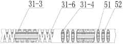
柔性臂由第一臂、第二臂、第三臂和第四臂依次连接制成一体,第一臂和第二臂连接处开有若干个方向一致的第一三角形开口,第三臂和第四臂上各开有一组方向一致的第二三角形开口,第三臂上的一组第二三角形开口与第四臂上的一组第二三角形开口之间的角度为90°;The flexible arm is formed by sequentially connecting the first arm, the second arm, the third arm and the fourth arm. There are several first triangular openings in the same direction at the junction of the first arm and the second arm. Each of the four arms is provided with a group of second triangular openings in the same direction, and the angle between the group of second triangular openings on the third arm and the group of second triangular openings on the fourth arm is 90°;
驱动箱内设有柔性臂支架传动机构,柔性臂支架传动机构包括第八电机、弹性联轴器、丝杠、丝杠支座、滑块、第二导轨、第一连杆、第二连杆和固定杆,第八电机的输出轴通过弹性联轴器与丝杠的一端传动连接,丝杠的另一端穿过滑块与丝杠支座转动连接,丝杠支座固装在支撑板上,支撑板上设有第二导轨,滑块的侧壁与第二导轨滑动连接,滑块的底端面上水平设置第一连杆,第一连杆的一端与第二连杆的一端铰接,第二连杆的另一端与第一柔性臂支架的侧壁铰接,第一柔性臂支架的一端通过固定夹与柔性臂的第三臂固接,第二柔性臂支架的一端通过固定夹与柔性臂的第三臂固接,第一柔性臂支架的另一端与固定杆铰接,第二柔性臂支架的另一端与固定杆铰接,柔性臂的第一臂固装在固定杆上,固定杆的另一端固装在支撑板上;The driving box is provided with a flexible arm support transmission mechanism, and the flexible arm support transmission mechanism includes an eighth motor, an elastic coupling, a lead screw, a lead screw support, a slider, a second guide rail, a first connecting rod, and a second connecting rod and the fixed rod, the output shaft of the eighth motor is connected to one end of the lead screw through an elastic coupling, the other end of the lead screw passes through the slider and is connected to the lead screw support in rotation, and the lead screw support is fixed on the support plate , the support plate is provided with a second guide rail, the side wall of the slider is slidingly connected with the second guide rail, the bottom end surface of the slider is horizontally provided with a first connecting rod, and one end of the first connecting rod is hinged with one end of the second connecting rod, The other end of the second connecting rod is hinged with the side wall of the first flexible arm support, one end of the first flexible arm support is affixed to the third arm of the flexible arm through the fixing clip, and one end of the second flexible arm support is connected to the flexible arm through the fixing clip. The third arm of the arm is fixedly connected, the other end of the first flexible arm support is hinged with the fixed rod, the other end of the second flexible arm support is hinged with the fixed rod, the first arm of the flexible arm is fixed on the fixed rod, and the fixed rod The other end is fixed on the support plate;
第三驱动丝的两端均绕过第二导向柱进入到柔性臂内与柔性臂的第三臂固接;第四驱动丝的两端均绕过第二导向柱进入到柔性臂内与柔性臂的第四臂固接,第三驱动丝的两端的连线与第四驱动丝的两端的连线垂直;Both ends of the third driving wire bypass the second guide post and enter the flexible arm to be fixedly connected to the third arm of the flexible arm; both ends of the fourth driving wire bypass the second guide post and enter the flexible arm to connect with the flexible arm The fourth arm of the arm is fixedly connected, and the line connecting the two ends of the third driving wire is perpendicular to the connecting line between the two ends of the fourth driving wire;
柔性臂的第四臂设在轴转关节一端的内部且二者固接,轴转关节的另一端内装有腕部连接杆的一端且二者转动连接;The fourth arm of the flexible arm is arranged inside one end of the pivot joint and the two are fixedly connected, and the other end of the pivot joint is equipped with one end of the wrist connecting rod and the two are rotationally connected;
第五驱动丝的一端绕过第三导向柱穿过柔性臂依次经过第一组导向轮径向缠绕腕部连接杆后固定在腕部连接杆上,第五驱动丝的另一端绕过第三导向柱穿过柔性臂依次经过第二组导向轮径向缠绕腕部连接杆后固定在腕部连接杆上,第一组导向轮和第二组导向轮分别装在固定夹板上,两组固定夹板分别装在轴转关节的外壁上且沿轴转关节的水平中心轴线对称设置;One end of the fifth driving wire goes around the third guide column, passes through the flexible arm, passes through the first set of guide wheels, wraps radially around the wrist connecting rod, and is fixed on the wrist connecting rod, and the other end of the fifth driving wire goes around the third The guide column passes through the flexible arm and then passes through the second set of guide wheels to radially wrap around the wrist connecting rod and then fixes on the wrist connecting rod. The first set of guide wheels and the second set of guide wheels are installed on the fixed splint respectively. The splints are installed on the outer wall of the pivot joint and arranged symmetrically along the horizontal central axis of the pivot joint;
腕关节由夹持钳导向轮和夹持钳制成一体构成,腕部连接杆的另一端设有两个安装耳,第一轴沿腕部连接杆的径向穿过安装耳和夹持钳导向轮并固装在安装耳上,第六驱动丝的两端均绕过第三导向柱依次穿过柔性臂、两个深沟球轴承和腕部连接杆后与腕关节的夹持钳导向轮固接;The wrist joint is composed of clamp guide wheels and clamp clamps. The other end of the wrist connecting rod is provided with two mounting ears. The first axis passes through the mounting ears and the clamping clamp along the radial direction of the wrist connecting rod. The two ends of the sixth driving wire go around the third guide column and pass through the flexible arm, two deep groove ball bearings and the wrist connecting rod in sequence, and then connect with the guide wheel of the clamping clamp of the wrist joint. Fixed;
夹持钳上各装有第一手指和第二手指,第一驱动丝的两端均绕过第一导向柱依次穿过柔性臂、两个深沟球轴承和腕部连接杆后经过导向辊与第一手指固接;第二驱动丝的两端均绕过第一导向柱依次穿过柔性臂、两个深沟球轴承和腕部连接杆后经过导向辊与第二手指固接,导向辊套装在第二轴上且二者转动连接,第二轴固定在夹持钳的开启位置处。The clamping pliers are respectively equipped with a first finger and a second finger, and both ends of the first driving wire go around the first guide post, pass through the flexible arm, two deep groove ball bearings and the wrist connecting rod, and then pass through the guide roller It is fixedly connected with the first finger; both ends of the second driving wire go around the first guide column and pass through the flexible arm, two deep groove ball bearings and the wrist connecting rod in turn, and then pass through the guide roller and are fixedly connected with the second finger, guiding The roller is sleeved on the second shaft and the two are rotatably connected, and the second shaft is fixed at the opening position of the clamping pliers.
本发明具有以下有益效果:驱动箱中的电机驱动整个机械臂系统中所有主动自由度关节的运动。第一柔性臂支架和第二柔性臂支架固连并托着柔性臂的初始段,起到对柔性臂的支撑作用,在机器人进入人体后打开时也可以起到初步定位的作用。柔性臂开有三角形切口,管臂内嵌驱动丝,通过驱动丝的牵引实现柔性关节的转动;两段交叉90°的三角形切口关节便可以实现整个柔性臂的横摆和俯仰两个自由度;轴转关节帮助腕部、第一手指及第二手指实现轴转;腕关节可以实现横摆运动,第一手指及第二手指独立开合运动用于手术过程中病灶的操作;The invention has the following beneficial effects: the motor in the driving box drives the motion of all the joints with active degrees of freedom in the whole mechanical arm system. The first flexible arm support and the second flexible arm support are fixedly connected and support the initial section of the flexible arm, which plays a role in supporting the flexible arm, and can also play a role in preliminary positioning when the robot enters the human body and opens. The flexible arm has a triangular incision, and the driving wire is embedded in the tubular arm, and the rotation of the flexible joint is realized through the traction of the driving wire; two joints crossing 90° with a triangular incision can realize the two degrees of freedom of the entire flexible arm in yaw and pitch; The pivoting joint helps the wrist, the first finger and the second finger to realize the pivoting; the wrist joint can realize the lateral movement, and the independent opening and closing movement of the first finger and the second finger is used for the operation of the lesion during the operation;
本发明可以有效的减小目前的微创腹腔手术机器人的结构尺寸,减少患者皮肤的切口数量,增强手术的可操作性和精度,降低病人手术的痛苦,减少术后的恢复时间。The invention can effectively reduce the structural size of the current minimally invasive abdominal surgery robot, reduce the number of incisions on the patient's skin, enhance the operability and precision of the operation, reduce the pain of the patient's operation, and reduce the postoperative recovery time.
附图说明Description of drawings
图1是本发明的整体结构示意图,图2是柔性臂的第三臂和第四臂的结构剖视图,图3是轴转关节的结构剖视图,图4是腕关节、第一手指和第二手指部分的结构示意图。Fig. 1 is a schematic view of the overall structure of the present invention, Fig. 2 is a structural cross-sectional view of the third arm and the fourth arm of the flexible arm, Fig. 3 is a structural cross-sectional view of the pivot joint, Fig. 4 is a wrist joint, the first finger and the second finger Schematic diagram of part of the structure.
具体实施方式Detailed ways
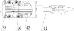
具体实施方式一:结合图1-图4说明本实施方式,本实施方式的机器人包括第一电机1、驱动箱2、第一导轨3、底座4、支撑板5、第二电机6、第三电机7、第四电机8、第五电机9、第六电机10、第七电机11、第一导向柱12、第二导向柱13、第三导向柱14、第一驱动丝16、第二驱动丝17、第三驱动丝18、第四驱动丝19、第五驱动丝20、第六驱动丝21、第一柔性臂支架30、柔性臂31、第二柔性臂支架32、轴转关节33、腕部连接杆34、第一组导向轮35、第二组导向轮36、腕关节38、夹持钳导向轮39、夹持钳40、第一手指43、第二手指44、导向辊45、第一轴46、第二轴47、固定夹53、两组固定夹板37、两个安装耳41、两个深沟球轴承42和六个驱动轮15;Specific Embodiment 1: This embodiment is described in conjunction with Fig. 1-Fig. Motor 7, fourth motor 8, fifth motor 9, sixth motor 10, seventh motor 11, first guide post 12, second guide post 13, third guide post 14, first drive wire 16, second drive Wire 17, third driving wire 18, fourth driving wire 19, fifth driving wire 20, sixth driving wire 21, first flexible arm support 30, flexible arm 31, second flexible arm support 32, pivot joint 33, Wrist connecting rod 34, first
第一电机1的输出轴与驱动箱2的侧壁传动连接,驱动箱2通过第一导轨3在底座4上滑动;The output shaft of the first motor 1 is in transmission connection with the side wall of the drive box 2, and the drive box 2 slides on the base 4 through the first guide rail 3;
驱动箱2内还设有支撑板5,支撑板5上依次平行设置第二电机6、第三电机7、第四电机8、第五电机9、第六电机10和第七电机11,第一导向柱12、第二导向柱13和第三导向柱14设在支撑板5上,第二电机6、第三电机7、第四电机8、第五电机9、第六电机10和第七电机11的输出轴上均装有驱动轮15,第一驱动丝16绕在第二电机输出轴上的驱动轮上,第二驱动丝17绕在第三电机输出轴上的驱动轮上,第三驱动丝18绕在第四电机输出轴上的驱动轮上,第四驱动丝19绕在第五电机输出轴上的驱动轮上,第五驱动丝20绕在第六电机输出轴上的驱动轮上,第六驱动丝21绕在第七电机输出轴上的驱动轮上;Also be provided with support plate 5 in the drive box 2, second motor 6, the 3rd motor 7, the 4th motor 8, the 5th motor 9, the 6th motor 10 and the 7th motor 11 are arranged in parallel successively on the support plate 5, the first Guide column 12, the second guide column 13 and the 3rd guide column 14 are located on the support plate 5, the second motor 6, the 3rd motor 7, the 4th motor 8, the 5th motor 9, the 6th motor 10 and the 7th motor The output shaft of 11 is equipped with driving wheel 15, the first driving wire 16 is wound on the driving wheel on the second motor output shaft, the second driving wire 17 is wound on the driving wheel on the third motor output shaft, the third The driving wire 18 is wound on the driving wheel on the fourth motor output shaft, the fourth driving wire 19 is wound on the driving wheel on the fifth motor output shaft, and the fifth driving wire 20 is wound on the driving wheel on the sixth motor output shaft On, the sixth driving wire 21 is wound on the driving wheel on the output shaft of the seventh motor;
柔性臂31由第一臂31-1、第二臂31-2、第三臂31-3和第四臂31-4依次连接制成一体,第一臂31-1和第二臂31-2连接处开有若干个方向一致的第一三角形开口31-5,第三臂31-3和第四臂31-4上各开有一组方向一致的第二三角形开口31-6,第三臂31-3上的一组第二三角形开口31-6与第四臂31-4上的一组第二三角形开口31-6之间的角度为90°;The flexible arm 31 is sequentially connected into one by the first arm 31-1, the second arm 31-2, the third arm 31-3 and the fourth arm 31-4, the first arm 31-1 and the second arm 31-2 There are several first triangular openings 31-5 in the same direction at the joint, and a set of second triangular openings 31-6 in the same direction are respectively opened on the third arm 31-3 and the fourth arm 31-4. The angle between the group of second triangular openings 31-6 on the -3 and the group of second triangular openings 31-6 on the fourth arm 31-4 is 90°;
驱动箱2内设有柔性臂支架传动机构,柔性臂支架传动机构包括第八电机22、弹性联轴器22-1、丝杠23、丝杠支座23-1、滑块24、第二导轨25、第一连杆26、第二连杆27和固定杆28,第八电机22的输出轴通过弹性联轴器22-1与丝杠23的一端传动连接,丝杠23的另一端穿过滑块24与丝杠支座23-1转动连接,丝杠支座23-1固装在支撑板5上,支撑板5上设有第二导轨25,滑块24的侧壁与第二导轨25滑动连接,滑块24的底端面上水平设置第一连杆26,第一连杆26的一端与第二连杆27的一端铰接,第二连杆27的另一端与第一柔性臂支架30的侧壁铰接,第一柔性臂支架30的一端通过固定夹53与柔性臂31的第三臂31-3固接,第二柔性臂支架32的一端通过固定夹53与柔性臂31的第三臂31-3固接,第一柔性臂支架30的另一端与固定杆28铰接,第二柔性臂支架32的另一端与固定杆28铰接,柔性臂31的第一臂31-1固装在固定杆28上,固定杆28的另一端固装在支撑板5上;The driving box 2 is provided with a flexible arm support transmission mechanism, and the flexible arm support transmission mechanism includes an eighth motor 22, an elastic coupling 22-1, a lead screw 23, a lead screw support 23-1, a slide block 24, and a second guide rail 25. The first connecting rod 26, the second connecting rod 27 and the fixed rod 28, the output shaft of the eighth motor 22 is connected to one end of the lead screw 23 through the elastic coupling 22-1, and the other end of the lead screw 23 passes through The slide block 24 is rotationally connected with the lead screw support 23-1, the lead screw support 23-1 is fixed on the support plate 5, the support plate 5 is provided with a second guide rail 25, and the side wall of the slide block 24 is connected to the second guide rail. 25 sliding connection, the first connecting rod 26 is horizontally arranged on the bottom end surface of the slider 24, and one end of the first connecting rod 26 is hinged with one end of the second connecting rod 27, and the other end of the second connecting rod 27 is connected with the first flexible arm support The sidewall of 30 is hinged, and one end of the first flexible arm support 30 is fixedly connected with the third arm 31-3 of the flexible arm 31 by the fixing clip 53, and one end of the second flexible arm support 32 is connected with the third arm 31-3 of the flexible arm 31 by the fixing clip 53. The three arms 31-3 are fixedly connected, the other end of the first flexible arm support 30 is hinged with the fixed rod 28, the other end of the second flexible arm support 32 is hinged with the fixed rod 28, and the first arm 31-1 of the flexible arm 31 is fixed. On the fixed rod 28, the other end of the fixed rod 28 is fixed on the support plate 5;
第三驱动丝18的两端均绕过第二导向柱13进入到柔性臂31内与柔性臂31的第三臂31-3固接;第四驱动丝19的两端均绕过第二导向柱13进入到柔性臂31内与柔性臂31的第四臂31-4固接,第三驱动丝18的两端的连线与第四驱动丝19的两端的连线垂直;Both ends of the third driving wire 18 bypass the second guide column 13 and enter into the flexible arm 31 to be fixedly connected with the third arm 31-3 of the flexible arm 31; both ends of the fourth driving wire 19 bypass the second guide The column 13 enters the flexible arm 31 and is fixedly connected to the fourth arm 31-4 of the flexible arm 31, and the connection line between the two ends of the third driving wire 18 is perpendicular to the connection line between the two ends of the fourth driving wire 19;
柔性臂31的第四臂31-4设在轴转关节33一端的内部且二者固接,轴转关节33的另一端内装有腕部连接杆34的一端且二者转动连接;The fourth arm 31-4 of the flexible arm 31 is located inside one end of the pivot joint 33 and the two are fixedly connected, and the other end of the pivot joint 33 is equipped with an end of the wrist connecting rod 34 and the two are rotationally connected;
第五驱动丝20的一端绕过第三导向柱14穿过柔性臂31依次经过第一组导向轮35径向缠绕腕部连接杆34后固定在腕部连接杆34上,第五驱动丝20的另一端绕过第三导向柱14穿过柔性臂31依次经过第二组导向轮36径向缠绕腕部连接杆34后固定在腕部连接杆34上,第一组导向轮35和第二组导向轮36分别装在固定夹板37上,两组固定夹板37分别装在轴转关节33的外壁上且沿轴转关节33的水平中心轴线对称设置;One end of the fifth driving wire 20 is fixed on the wrist connecting rod 34 after being wound around the wrist connecting rod 34 radially through the first set of
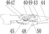
腕关节38由夹持钳导向轮39和夹持钳40制成一体构成,腕部连接杆34的另一端设有两个安装耳41,第一轴46沿腕部连接杆34的径向穿过安装耳41和夹持钳导向轮39并固装在安装耳41上,第六驱动丝21的两端均绕过第三导向柱14依次穿过柔性臂31、两个深沟球轴承42和腕部连接杆34后与腕关节38的夹持钳导向轮39固接;Wrist joint 38 is made integrally by clamping pliers guide wheel 39 and clamping pliers 40, and the other end of wrist connecting rod 34 is provided with two
夹持钳40上各装有第一手指43和第二手指44,第一驱动丝16的两端均绕过第一导向柱12依次穿过柔性臂31、两个深沟球轴承42和腕部连接杆34后经过导向辊45与第一手指43固接;第二驱动丝17的两端均绕过第一导向柱12依次穿过柔性臂31、两个深沟球轴承42和腕部连接杆34后经过导向辊45与第二手指44固接,导向辊45套装在第二轴47上且二者转动连接,第二轴47固定在夹持钳的开启位置处。A
具体实施方式二:结合图1和图4说明本实施方式,本实施方式的机器人还包括固定轴48,夹持钳40与第一手指43和第二手指44的连接方式是固定轴48穿过夹持钳40且与夹持钳导向轮39的径向在同一直线上,第一手指43的末端设有第一连接环49,第二手指44的末端设有第二连接环50,第一连接环49和第二连接环50套装在固定轴48上,此结构的优点是第二电机和第三电机通过第一驱动丝和第二驱动丝可以灵活的驱动第一手指和第二手指,实现第一手指和第二手指的灵活运动。其它实施方式与具体实施方式一相同。Specific embodiment two: This embodiment is described in conjunction with Fig. 1 and Fig. 4, and the robot of this embodiment also includes fixed
具体实施方式三:本实施方式的柔性臂31为镍钛诺材质的柔性臂,此种材质的优点是保证一定刚度的前提下具有很大的弹性变形。其它实施方式与具体实施方式一相同。Embodiment 3: The flexible arm 31 of this embodiment is a flexible arm made of Nitinol material. The advantage of this material is that it has a large elastic deformation under the premise of ensuring a certain rigidity. Other implementation manners are the same as the specific implementation manner 1.
具体实施方式四:结合图说明2本实施方式,本实施方式的机器人还包括多个固定片51,柔性臂31内装有多个间隔设置的所述固定片51,每个固定片51上开有若干个驱动丝孔52。此结构的优点是多个固定片51能够对驱动丝很好的限位。其它实施方式与具体实施方式一相同。Specific Embodiment 4: In conjunction with Figure 2, this embodiment is described. The robot of this embodiment also includes a plurality of fixed
工作原理:所述驱动箱2通过第一导轨与底座4相连,由固定于底座上的第一电机1来进行驱动,来实现整个柔性臂在病人腹腔的深入伸出;第二电机6通过第一驱动丝16驱动第一手指43开合运动;第三电机7通过第二驱动丝17驱动第二手指44开合运动;第四电机8通过第三驱动丝18驱动柔性关节臂31的第三臂31-3俯仰运动;第五电机9通过第四驱动丝19驱动柔性关节臂31的第四臂31-4横摆运动;第六电机10通过第五驱动丝20驱动轴转关节33进行轴转运动;第七电机11通过第六驱动丝21驱动腕关节38进行俯仰运动;第八电机22通过丝杠22和第二导轨25对第一连杆26和第二连杆27进行前后方向驱动,从而使第一柔性支架30和第二柔性支架32运动,实现柔性臂31在Y方向的打开。Working principle: the drive box 2 is connected to the base 4 through the first guide rail, and is driven by the first motor 1 fixed on the base to realize the deep extension of the entire flexible arm in the patient's abdominal cavity; the second motor 6 passes through the first A drive wire 16 drives the
Claims (4)
Translated fromChinesePriority Applications (1)
| Application Number | Priority Date | Filing Date | Title |
|---|---|---|---|
| CN201210204214.1ACN102697564B (en) | 2012-06-20 | 2012-06-20 | Flexible-arm robot for minimally invasive single-port abdominal surgery |
Applications Claiming Priority (1)
| Application Number | Priority Date | Filing Date | Title |
|---|---|---|---|
| CN201210204214.1ACN102697564B (en) | 2012-06-20 | 2012-06-20 | Flexible-arm robot for minimally invasive single-port abdominal surgery |
Publications (2)
| Publication Number | Publication Date |
|---|---|
| CN102697564A CN102697564A (en) | 2012-10-03 |
| CN102697564Btrue CN102697564B (en) | 2014-04-23 |
Family
ID=46890828
Family Applications (1)
| Application Number | Title | Priority Date | Filing Date |
|---|---|---|---|
| CN201210204214.1AActiveCN102697564B (en) | 2012-06-20 | 2012-06-20 | Flexible-arm robot for minimally invasive single-port abdominal surgery |
Country Status (1)
| Country | Link |
|---|---|
| CN (1) | CN102697564B (en) |
Families Citing this family (27)
| Publication number | Priority date | Publication date | Assignee | Title |
|---|---|---|---|---|
| CN103006329B (en)* | 2012-12-03 | 2014-10-15 | 上海交通大学 | Multi-joint single-wound abdominal cavity minimally-invasive surgery robot and operating mechanism thereof |
| CN103083091B (en)* | 2013-01-28 | 2014-11-26 | 哈尔滨工业大学 | Inclined angle flexible needle robot auxiliary puncture system based on piezoelectric actuation |
| CN103536365B (en)* | 2013-10-22 | 2015-10-28 | 同济大学 | A kind of guiding device for Minimally Invasive Surgery concentric tube robot |
| CN104758012B (en)* | 2015-04-07 | 2017-04-12 | 哈尔滨工业大学 | Tail end instrument for single port laparoscopy minimally invasive surgery flexible robot with multiple freedom degrees |
| CN104758013B (en)* | 2015-04-07 | 2017-02-22 | 哈尔滨工业大学 | Driving mechanism for multi-degree-of-freedom flexible robot for single-incision laparoscopic minimally invasive surgery |
| CN104887313A (en)* | 2015-04-07 | 2015-09-09 | 哈尔滨工业大学 | Flexible arm for multi-degree-of-freedom flexible robot for single-hole abdominal minimally invasive surgery |
| CN104758060B (en)* | 2015-04-07 | 2017-01-11 | 哈尔滨工业大学 | Multi-degree-of-freedom flexible robot used for single-port celiac minimally invasive surgery |
| CN105455902B (en)* | 2015-11-23 | 2018-10-16 | 微创(上海)医疗机器人有限公司 | Robot wrist and operating robot |
| CN105287002B (en)* | 2015-12-02 | 2017-10-27 | 吉林大学 | A kind of robot assisted Minimally Invasive Surgery micro- apparatus of Flexible Multi-joint operation |
| CN106236269B (en) | 2016-08-31 | 2018-09-04 | 北京术锐技术有限公司 | A kind of multivariant flexible operation tool |
| CN106419975B (en)* | 2016-11-23 | 2018-06-26 | 中国人民解放军第二军医大学 | A kind of transurethral electric drive multiple degrees of freedom surgery systems |
| CN106473810B (en)* | 2016-11-23 | 2018-06-26 | 中国人民解放军第二军医大学 | A kind of transurethral flexible operation tool |
| CN106510849B (en)* | 2016-11-23 | 2018-02-23 | 中国人民解放军第二军医大学 | A kind of transurethral surgical robot system |
| CN106510848B (en)* | 2016-11-23 | 2018-06-26 | 中国人民解放军第二军医大学 | A kind of transurethral operating robot and control system |
| CN107049494B (en)* | 2017-05-09 | 2024-01-26 | 深圳市罗伯医疗科技有限公司 | Medical device based on digestive endoscope |
| CN108567487A (en)* | 2018-03-23 | 2018-09-25 | 深圳市精锋医疗科技有限公司 | With adjustable link from operation equipment and operating robot |
| CN109481021B (en)* | 2018-10-25 | 2021-11-16 | 天津大学 | Mode reconstruction type minimally invasive surgery robot slave hand system |
| WO2020082291A1 (en)* | 2018-10-25 | 2020-04-30 | 天津大学 | Mode-reconfigurable minimally invasive surgery robot slave manipulator system |
| CN110522517A (en)* | 2019-09-16 | 2019-12-03 | 西安交通大学医学院第一附属医院 | A robotic arm for minimally invasive surgery in a single-port laparoscopic environment |
| CN110711032B (en)* | 2019-10-21 | 2020-08-25 | 山东大学 | A miniaturized surgical robot with a rear motor |
| CN110811840B (en)* | 2019-11-22 | 2020-11-17 | 山东大学 | Variable-rigidity wrist structure of surgical robot and surgical mechanical arm |
| CN111956328B (en)* | 2020-07-28 | 2021-09-28 | 哈尔滨工业大学(深圳) | Continuum robot for minimally invasive surgery |
| CN112022238B (en)* | 2020-08-28 | 2021-06-15 | 中国科学院沈阳自动化研究所 | Surgical instrument for minimally invasive surgery robot |
| CN112370167B (en)* | 2020-11-10 | 2022-03-29 | 北京邮电大学 | Robotic Surgical Instrument Arm and Minimally Invasive Surgical Robot for Various Holes |
| CN113057570B (en)* | 2021-03-16 | 2023-06-02 | 上海微创微航机器人有限公司 | Bronchoscope, scope holding arm, controllable sheath, operation method and patient end device |
| CN113081280B (en)* | 2021-04-09 | 2022-07-22 | 哈尔滨工业大学(深圳) | Multi-arm robot for single-hole minimally invasive surgery |
| CN113208737B (en)* | 2021-06-08 | 2023-04-28 | 山东大学 | Limited continuum for single-hole surgical robot |
Citations (4)
| Publication number | Priority date | Publication date | Assignee | Title |
|---|---|---|---|---|
| CN101073487A (en)* | 2006-05-19 | 2007-11-21 | 伊西康内外科公司 | Cavity stabilizer for endoscope mucosal resection |
| CN101390763A (en)* | 2008-10-31 | 2009-03-25 | 天津大学 | Robot body system for assisting minimally invasive surgery |
| CN101411632A (en)* | 2008-12-03 | 2009-04-22 | 天津大学 | Robot active bracket for assisting minimally invasive surgical operation |
| CN101889900A (en)* | 2010-07-12 | 2010-11-24 | 天津大学 | Master-slave integrated robotic arm for assisting minimally invasive surgery |
Family Cites Families (3)
| Publication number | Priority date | Publication date | Assignee | Title |
|---|---|---|---|---|
| AU2003224436A1 (en)* | 2003-04-04 | 2004-10-25 | Universita' Cattolica Del Sacro Cuore | Endoscopic instrument with two independent arms |
| JP2008302097A (en)* | 2007-06-11 | 2008-12-18 | Hoya Corp | Clip device for endoscope |
| DE102010044106A1 (en)* | 2010-11-18 | 2012-05-24 | Siemens Aktiengesellschaft | instrument system |
- 2012
- 2012-06-20CNCN201210204214.1Apatent/CN102697564B/enactiveActive
Patent Citations (4)
| Publication number | Priority date | Publication date | Assignee | Title |
|---|---|---|---|---|
| CN101073487A (en)* | 2006-05-19 | 2007-11-21 | 伊西康内外科公司 | Cavity stabilizer for endoscope mucosal resection |
| CN101390763A (en)* | 2008-10-31 | 2009-03-25 | 天津大学 | Robot body system for assisting minimally invasive surgery |
| CN101411632A (en)* | 2008-12-03 | 2009-04-22 | 天津大学 | Robot active bracket for assisting minimally invasive surgical operation |
| CN101889900A (en)* | 2010-07-12 | 2010-11-24 | 天津大学 | Master-slave integrated robotic arm for assisting minimally invasive surgery |
Also Published As
| Publication number | Publication date |
|---|---|
| CN102697564A (en) | 2012-10-03 |
Similar Documents
| Publication | Publication Date | Title |
|---|---|---|
| CN102697564B (en) | Flexible-arm robot for minimally invasive single-port abdominal surgery | |
| CN112842534B (en) | Surgical tool system | |
| WO2021184791A1 (en) | Serpentine surgical robot applied to minimally invasive surgery | |
| EP3556520B1 (en) | Remote-center-of-motion mechanism | |
| CN111888012B (en) | Surgical instrument platform | |
| CN104758060B (en) | Multi-degree-of-freedom flexible robot used for single-port celiac minimally invasive surgery | |
| CN109009443A (en) | Abdominal minimally invasive surgery robot | |
| CN106175850A (en) | The flexible operation tool system that a kind of straight line driving mechanism drives | |
| CN104337579B (en) | A kind of series-parallel connection manipulator for Minimally Invasive Surgery | |
| CN104814792B (en) | Separable multi-arm soft robotic arm device | |
| CN104116547A (en) | Low-friction low-inertia surgical instrument for minimally invasive surgical robot | |
| CN104398303B (en) | A kind of series-parallel connection manipulator for Minimally Invasive Surgery | |
| CN104758012B (en) | Tail end instrument for single port laparoscopy minimally invasive surgery flexible robot with multiple freedom degrees | |
| CN108042208A (en) | Micro-wound operation robot master arm | |
| CN105287003A (en) | Mechanical arm and work method thereof | |
| CN106308935A (en) | Flexible surgical operation tool system driven by twin thread screw | |
| CN105997251A (en) | Four-freedom-degree series-parallel minimally invasive surgery manipulator | |
| CN113786242A (en) | Four-freedom-degree decoupling actuator of surgical robot | |
| CN205268284U (en) | Abdominal cavity minimal access surgery holds mirror robot | |
| CN221671972U (en) | Laparoscopic minimally invasive robotic surgical arm | |
| CN108309456A (en) | A kind of quick-changing mechanism of control decoupling for single hole operating robot | |
| CN219070434U (en) | Instrument transmission device, surgical instrument and surgical robot | |
| CN215273286U (en) | A low-torque-driven minimally invasive surgical robotic arm RCM mechanism | |
| CN116407215A (en) | Wearable multi-degree-of-freedom bendable surgical instrument | |
| CN108158660A (en) | A kind of single hole surgical robot quick replacement mechanism of the control decoupling with linear joint |
Legal Events
| Date | Code | Title | Description |
|---|---|---|---|
| C06 | Publication | ||
| PB01 | Publication | ||
| C10 | Entry into substantive examination | ||
| SE01 | Entry into force of request for substantive examination | ||
| C14 | Grant of patent or utility model | ||
| GR01 | Patent grant |