CN102695470A - intraosseous dental implant - Google Patents
intraosseous dental implantDownload PDFInfo
- Publication number
- CN102695470A CN102695470ACN2010800559650ACN201080055965ACN102695470ACN 102695470 ACN102695470 ACN 102695470ACN 2010800559650 ACN2010800559650 ACN 2010800559650ACN 201080055965 ACN201080055965 ACN 201080055965ACN 102695470 ACN102695470 ACN 102695470A
- Authority
- CN
- China
- Prior art keywords
- dental implant
- blade
- central body
- implant according
- bone
- Prior art date
- Legal status (The legal status is an assumption and is not a legal conclusion. Google has not performed a legal analysis and makes no representation as to the accuracy of the status listed.)
- Pending
Links
- 239000004053dental implantSubstances0.000titleclaimsabstractdescription37
- 239000007943implantSubstances0.000claimsabstractdescription64
- 210000000988bone and boneAnatomy0.000claimsabstractdescription37
- 238000003780insertionMethods0.000claimsabstractdescription14
- 230000037431insertionEffects0.000claimsabstractdescription14
- RTAQQCXQSZGOHL-UHFFFAOYSA-NTitaniumChemical compound[Ti]RTAQQCXQSZGOHL-UHFFFAOYSA-N0.000claimsdescription3
- 239000000463materialSubstances0.000claimsdescription3
- 229910052719titaniumInorganic materials0.000claimsdescription3
- 239000010936titaniumSubstances0.000claimsdescription3
- 229910000838Al alloyInorganic materials0.000claimsdescription2
- 229910000756V alloyInorganic materials0.000claimsdescription2
- XAGFODPZIPBFFR-UHFFFAOYSA-NaluminiumChemical compound[Al]XAGFODPZIPBFFR-UHFFFAOYSA-N0.000claimsdescription2
- 239000011248coating agentSubstances0.000claims1
- 238000000576coating methodMethods0.000claims1
- 239000003086colorantSubstances0.000claims1
- 230000003247decreasing effectEffects0.000claims1
- 239000000203mixtureSubstances0.000claims1
- 238000004873anchoringMethods0.000description4
- 238000000034methodMethods0.000description4
- 206010003694AtrophyDiseases0.000description2
- MCMNRKCIXSYSNV-UHFFFAOYSA-NZirconium dioxideChemical compoundO=[Zr]=OMCMNRKCIXSYSNV-UHFFFAOYSA-N0.000description2
- 230000037444atrophyEffects0.000description2
- 230000001054cortical effectEffects0.000description2
- 210000001983hard palateAnatomy0.000description2
- 208000015181infectious diseaseDiseases0.000description2
- 230000010354integrationEffects0.000description2
- 238000001356surgical procedureMethods0.000description2
- 230000001720vestibularEffects0.000description2
- 229910001069Ti alloyInorganic materials0.000description1
- 229910004349Ti-AlInorganic materials0.000description1
- 229910004692Ti—AlInorganic materials0.000description1
- 230000006978adaptationEffects0.000description1
- 230000001580bacterial effectEffects0.000description1
- 229910010293ceramic materialInorganic materials0.000description1
- 210000002808connective tissueAnatomy0.000description1
- 230000007423decreaseEffects0.000description1
- 238000006073displacement reactionMethods0.000description1
- 238000005516engineering processMethods0.000description1
- 210000003823hyoid boneAnatomy0.000description1
- 210000001847jawAnatomy0.000description1
- 210000002050maxillaAnatomy0.000description1
- 238000003801millingMethods0.000description1
- 230000035755proliferationEffects0.000description1
- 230000001172regenerating effectEffects0.000description1
- 229910052715tantalumInorganic materials0.000description1
- GUVRBAGPIYLISA-UHFFFAOYSA-Ntantalum atomChemical compound[Ta]GUVRBAGPIYLISA-UHFFFAOYSA-N0.000description1
Images

Classifications
- A—HUMAN NECESSITIES
- A61—MEDICAL OR VETERINARY SCIENCE; HYGIENE
- A61C—DENTISTRY; APPARATUS OR METHODS FOR ORAL OR DENTAL HYGIENE
- A61C8/00—Means to be fixed to the jaw-bone for consolidating natural teeth or for fixing dental prostheses thereon; Dental implants; Implanting tools
- A61C8/0018—Means to be fixed to the jaw-bone for consolidating natural teeth or for fixing dental prostheses thereon; Dental implants; Implanting tools characterised by the shape
- A61C8/0019—Blade implants
- A61C8/0021—Blade implants with self-incising cutting edge
Landscapes
- Health & Medical Sciences (AREA)
- Oral & Maxillofacial Surgery (AREA)
- Orthopedic Medicine & Surgery (AREA)
- Dentistry (AREA)
- Epidemiology (AREA)
- Life Sciences & Earth Sciences (AREA)
- Animal Behavior & Ethology (AREA)
- General Health & Medical Sciences (AREA)
- Public Health (AREA)
- Veterinary Medicine (AREA)
- Prostheses (AREA)
- Dental Prosthetics (AREA)
Abstract
Description
Translated fromChinese技术领域technical field
本发明涉及牙植入物。The present invention relates to dental implants.
现有技术current technology
如所已知的,当进行植牙时,牙钉在预定位置被固定到患者的颚或上颌骨上。这些植入物在顶部处还设有支座,牙残根钉(stump pin)或类似物被固定在该支座内。存在患者的要进行植入的骨的厚度非常小(例如从2.5mm到6mm)的情况,并且在这些情况下,植入物的插入非常困难,这是由于为了能够插入植入物需要使用特殊的骨移植物进行复杂的再生手术。通常,具有圆柱形横截面的主体的标准植入物需要骨嵴的厚度比其直径大至少2mm。As is known, when performing dental implants, dental pins are secured to the patient's jaw or maxilla in predetermined positions. These implants also have an abutment at the top, into which a stump pin or similar is secured. There are cases where the thickness of the patient's bone to be implanted is very small (for example from 2.5mm to 6mm) and in these cases the insertion of the implant is very difficult due to the special complex regenerative surgery using bone grafts. Typically, standard implants with a body of cylindrical cross-section require the thickness of the bone crest to be at least 2 mm greater than its diameter.
发明内容Contents of the invention
因此,本发明的目的是提供一种牙植入物,该牙植入物甚至可以被有利地施加到患者骨嵴的厚度很小的区域中,这种牙植入物具有有限的体积尺寸,在骨中提供最佳锚固,具有类似于标准尺寸植入物的表面区域,以及确保极好的主要稳定性。It is therefore an object of the present invention to provide a dental implant which can advantageously be applied even in regions of a patient's bone crest with a small thickness, which dental implant has limited volumetric dimensions, Provides optimal anchoring in bone, has a surface area similar to standard size implants, and ensures excellent primary stability.
这个目的通过本发明的牙植入物来实现,其特征在于,该牙植入物包括中心主体,该中心主体具有大体锥形或截头锥形的形状,并且该牙植入物具有从截面较大的端部延伸出的、能够接纳牙残根钉的连接座;该中心主体设有刃部,该刃部定位在所述中心主体的纵向中间平面中并且具有一长度以便凸伸超出所述中心主体的截面较小的端部;所述中心主体在冠状部分中也非常薄,以及所述刃部能够赋予植入物大体楔形的形式。This object is achieved by a dental implant according to the invention, characterized in that it comprises a central body having a generally conical or frusto-conical shape, and that the dental implant has a cross-sectional a socket extending from the larger end capable of receiving a root stud; the central body is provided with a blade positioned in the longitudinal median plane of said central body and having a length so as to protrude beyond the The smaller cross-sectional ends of the central body; the central body is also very thin in the coronal portion, and the blades are able to give the implant a generally wedge-shaped form.
根据本发明的另一个方面,所述牙植入物至少在所述中心主体和所述刃部的前表面或后表面上包括从所述表面伸出的至少一个纵向导肋。According to another aspect of the invention, said dental implant comprises, at least on the front or back surfaces of said central body and said blade, at least one longitudinal guide rib protruding from said surfaces.
根据本发明的又一个方面,所述中心主体和所述刃部具有为大约1°或更小的锥角,以便赋予该植入物大体刃状的形式。According to yet another aspect of the invention, said central body and said blade portion have a taper angle of about 1° or less, so as to give the implant a generally blade-like form.
本发明植入物的纵向肋和大体刃状形式的存在允许该植入物更容易且更精确地插入患者的骨内,这是因为该插入步骤沿着预定插入轴线进行,该预定插入轴线始终被保持而没有不期望的横向位移。该植入物因此具有甚至更大的主要稳定性,从而允许正确锚固,这防止可能的横向移动。而且,大体刃状的形式还确保将所述植入物甚至更有效地且简单地插入具有很小骨体积的骨区域内或者嵴萎缩的区域内。本发明植入物的这种快速且简单的插入有利地缩短手术时间,从而降低发生感染和骨损伤的危险。与具有刃部状形式的前述植入物不同的是,这种植入物具有在插入过程中使骨膨胀的功能,并且具有在标准植入物的正常尺寸范围内的宽度和体积,而且这些植入物中的每一个因此可以替换单个牙齿。The presence of the longitudinal ribs and the generally blade-like form of the implant of the present invention allows easier and more precise insertion of the implant into the patient's bone, since the insertion step is carried out along the predetermined insertion axis, which is always be held without undesired lateral displacement. The implant thus has even greater primary stability, allowing correct anchoring, which prevents possible lateral movements. Moreover, the substantially blade-like form also ensures an even more efficient and simple insertion of the implant into bone regions with little bone volume or into regions of cristae atrophy. This quick and simple insertion of the implant of the present invention advantageously reduces surgical time, thereby reducing the risk of infection and bone damage. Unlike the previous implants having a blade-like form, this implant has the function of expanding the bone during insertion and has a width and volume within the normal size range of standard implants, and these implants Each of the implants can thus replace a single tooth.
附图说明Description of drawings
在参照附图通过非限制性实例提供的下述说明的过程中,将更清楚地理解本发明的其它目的和优点,附图中:Other objects and advantages of the invention will become more clearly understood during the following description, given by way of non-limiting example with reference to the accompanying drawings, in which:
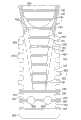
图1示出了根据本发明的牙植入物的第一实施例的主视图;Figure 1 shows a front view of a first embodiment of a dental implant according to the invention;
图2示出了根据图1的牙植入物的俯视平面图;Figure 2 shows a top plan view of the dental implant according to Figure 1;
图3示出了沿图2中的线III-III的横截面图;Figure 3 shows a cross-sectional view along line III-III in Figure 2;
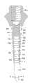
图4示出了根据本发明的牙植入物的第二实施例的主视图;Figure 4 shows a front view of a second embodiment of a dental implant according to the invention;
图5示出了沿图4中的线V-V的横截面图。FIG. 5 shows a cross-sectional view along line V-V in FIG. 4 .
具体实施方式Detailed ways
参照附图,特别是参照附图中的图1,附图标记1表示根据本发明的第一实施例的牙植入物的中心主体,该中心主体具有大体锥形或截头锥形的形状,而附图标记2表示长方形或正方形的刃部,该刃部从中心主体1的某一高度形成,并且沿所述中心主体的纵向中间平面布置。该刃部2包括端部部分102,该端部部分在底部延伸超出中心主体1的截面较小的一端部,并且在端部处设有横向末端202,该横向末端具有边缘,所述边缘被适当地倒圆角,以避免对患者的骨造成不期望的破坏。所述长方形刃部2和所述中心主体1因此赋予本发明的植入物大体楔形的形式。位于所述中心主体1的两个沿直径相对的表面上(在这个例子中,在中心主体的前表面和后表面上)的一系列横向齿101沿中心主体1的整个表面形成(请参见附图的图3)。具有合适尺寸的横向沟槽301形成于每对相邻的前横向齿和后横向齿101之间:具有较大深度的沟槽确保了高的主要稳定性,从而减小了植入物侧向和竖向的微小运动,而具有较小深度的沟槽确保了高的辅助稳定性,从而增加了植入物的表面积。中心主体1的具有较大截面的上部部分设有两个沿直径相对的平坦表面,所述平坦表面大体呈椭圆的弧的形式,即(参见附图中的图2)前平坦表面201和后平坦表面501。横向齿101也形成于这些平坦表面201和501中,并且延伸以便由这些平坦表面201和501限定边界。包括多个小齿的螺纹401形成于中心主体1的上部部分中,对应于骨内部件的颈部。在刃部的整个宽度上延伸的横向齿302也形成于刃部2的端部部分102的前表面和后表面上。也可以不提供形成于刃部2的末端202附近的一系列的横向齿302。由具有大体半圆形形状的合适沟槽502分开的一系列齿402沿刃部2的每一个纵向边缘的整个长度形成。刃部2的设有齿402的这些纵向边缘相对中心主体1对称地定位。刃部的端部部分102还具有在其中形成的一个或多个通孔602,例如两个通孔,所述通孔设计成一旦已经将植入物插入患者的骨内,就允许在骨内进行更快的血管化以及最佳的夹持和整合。With reference to the drawings, and in particular to Figure 1 of the drawings,
中心主体1的具有较大截面的上端部还在其中形成具有小锥角A的连接座701,该锥角可相对于普通的圆柱孔从约1°到约2°变化。圆筒形螺纹孔801设置在连接座701的底部处:用于本植入物的牙残根钉将接合在该座701内和该圆筒形螺纹孔801内。由于这个小的锥角A,可以获得一系列优点:将植入物的座701和要被插入该座内部的牙残根钉所谓地冷焊接在一起,结果是,有利地减小内部空间并且因此减小可能促使细菌增殖的空间:和水平的冠状区,该冠状区对于用于支撑结缔组织和骨的区域来说是有用的。The upper end of the
中心主体1和刃部2优选由钛/铝/钒合金、Ti-Al6-V4(纯钛或钛合金、钽、氧化锆、陶瓷材料或者使用其它生物相容性的和/或适合用于骨移植的材料)制成,并且植入物必须被插入的部位优选使用本身已知的压电外科手术技术和工艺(即“压电外科手术”),或者使用其它工艺(诸如超声工艺、激光工艺或者手动工具(诸如刀片或骨凿))进行处理。前齿101和后齿302按锯齿形式从中心主体1和刃部2的表面伸出,即设有能够便于将植入物插入患者的骨内的斜面,并且与沟槽301相结合,从而一旦已经将植入物插入患者的骨内就确保最优的锚固和稳定性。根据不同的结构型式,这些齿可以具有不同的形状。The
根据上面描述的本发明的实施例,由中心主体1和刃部2形成的并且具有大体楔形形状的植入物还可被有利地固定在患者的具有小厚度的骨区域中;这种楔形形式使皮层骨和松质骨都利用其粘弹性质而膨胀。因此,在对患者的骨进行微小的骨切开术或切口从而提供用于引入植入物的很薄部位之后,前庭皮质骨还可以相对于舌/腭骨膨胀。从生物学的角度来看,传统植入物和本发明植入物之间的差异是显著的,这是因为对于传统植入物来说,需要使用合适的铣刀从骨嵴移除对于植入物插入来说所必需的所有体积;而在本发明的植入物中,仅需要很薄的切口,该切口例如可以从0.1mm到1mm变化,因此,即使在存在薄骨嵴的情况下仍然保持前庭和腭骨的足够厚度。According to the embodiment of the invention described above, an implant formed by a
进一步改善植入物稳定性的合适形状的凹部901沿中心主体1的前表面和后表面(参见图4和图5)形成,其中相同的部件使用前面描述中所采用的相同附图标记来表示。该中心主体1在上部也包括连接座701,该连接座包括螺纹孔801,该螺纹孔用于插入本发明植入物的牙残根钉。在这个实施例中,通过具有大致半圆形形状的合适沟槽502分开的一系列齿402也沿刃部2的每个纵向边缘的整个长度形成。刃部2的设有齿402的这些纵向边缘相对于中心主体1对称地定位。一系列合适形状的凹部702相对于所述齿402或所述沟槽502形成在刃部2的前表面和后表面上。刃部的端部部分102还设有单个通孔602,该通孔设计成如上所述一旦已经将植入物插入患者的骨内,就允许在骨内进行更快的血管化以及最佳的夹持和整合。Suitably shaped
设计成在植入物插入患者骨内部的过程中正确引导该植入物的突出纵向肋3形成在所述中心主体1和所述刃部2的前表面和后表面中的每一个上而且优选在中心位置处。这些纵向肋3中的每一个帮助便于将植入物插入骨内,以便避免损坏骨本身并且稳定地保持植入物插入的预定轴线。而且,这些肋3还增加了植入物的主要稳定性,从而允许正确锚固,这防止了可能的横向移动。Protruding
优选地,这些纵向肋3是相同的,并且布置成相对于主体1和刃部2沿直径相对,但在其它实施例中,根据解剖学或生物力学的要求,它们也可以是单个的或者非对称的。这些肋3中的每一个具有位于植入物的上部部分中的厚度较大的顶端部和用于与刃部2连接的底端部。肋3的厚度因此从其顶端部朝向底端部减小,该肋3在底端部处与刃部2连接。根据其它实施例,这些肋可以具有变化且连续的厚度、形式和尺寸,或者具有锯齿形状、处于各种结构形式,这对于高度和厚度和对于密度和质量来说适于可用骨的解剖学变化。Preferably, these
中心主体1和刃部2被设计成赋予本发明的植入物大体刃状的形状;实际上,植入物的锥角B处于1°或更小的范围内。The
本发明植入物的第二实施例的刃状形式因此被有利地设计成具有很小厚度,允许植入物以简单且有效的方式用在骨容积非常小的区域中或者用在具有萎缩的嵴的区域中。可被插入的本发明植入物的简化还有利地缩短用于安装植入物的手术时间、减小感染的可能性以及减小对骨造成任何不期望的破坏。The blade-like form of the second embodiment of the implant of the invention is therefore advantageously designed to have a small thickness, allowing the implant to be used in a simple and effective manner in areas of very small bone volume or in areas with atrophy. in the region of the crest. The simplification of the implants of the present invention that can be inserted also advantageously reduces the surgical time for installing the implants, reduces the possibility of infection and reduces any undesired damage to the bone.
由于(在植入物和牙残根钉之间的)间接连接,本发明的植入物有利地与大多数众所周知的植入物制造商(sector 31,SwissPlus,Branemark,Straumann,Zimmer)的牙残根钉相兼容,在某些情况下,这种间接连接与植入物分开,并且因此能够在插入植入物之后的阶段被添加到该植入物上,在其它情况下,间接连接甚至已经形成植入物自身的一部分(因此形成单件),从而生成完整组件,该完整组件可能已经与其它植入物系统相结合而无需进一步的适应。这种植入物在牙颈上以及在从牙龈露出的部分中还设有美学装饰层。Due to the indirect connection (between the implant and the stump screw), the implant of the invention is advantageously compatible with dental implants of most well-known implant manufacturers (sector 31, SwissPlus, Branemark, Straumann, Zimmer). In some cases, this indirect connection is separate from the implant and can thus be added to the implant at a later stage after the implant is inserted, in other cases the indirect connection is even Having formed part of the implant itself (thus forming a single piece), a complete assembly is created which may already be integrated with other implant systems without further adaptation. Such implants are also provided with an aesthetic decorative layer on the neck and in the part emerging from the gums.
另外,尽管存在本发明的植入物具有使得其可被插入薄嵴中的尺寸特征这样的事实,然而该植入物还具有极好的强度和标准尺寸的表面区域(骨接触区域)以及假体(prosthetic)连接,不像已知的植入物那样,在尺寸(尤其是直径)减小之后,骨接触区域以及假体连接的强度和尺寸都减小。In addition, despite the fact that the implant of the present invention has dimensional features that allow it to be inserted into a thin crest, the implant also has excellent strength and a surface area of standard size (bone contact area) and false The prosthetic connection, unlike known implants, reduces both the strength and the size of the bone contact area as well as the prosthetic connection after a reduction in size (especially diameter).
Claims (21)
Translated fromChineseApplications Claiming Priority (6)
| Application Number | Priority Date | Filing Date | Title |
|---|---|---|---|
| ITGE2009A000097AIT1397334B1 (en) | 2009-12-11 | 2009-12-11 | CUNEIFORM DENTAL IMPLANT FOR LOW VOLUME. |
| ITGE2009A000097 | 2009-12-11 | ||
| ITGE2010A000056 | 2010-05-20 | ||
| IT000056AITGE20100056A1 (en) | 2010-05-20 | 2010-05-20 | "FLAT ENDO-BONE PLANT" |
| PCT/EP2010/069003WO2011069978A1 (en) | 2009-12-11 | 2010-12-06 | Endosseous dental implant |
| US201213514725A | 2012-06-08 | 2012-06-08 |
Publications (1)
| Publication Number | Publication Date |
|---|---|
| CN102695470Atrue CN102695470A (en) | 2012-09-26 |
Family
ID=60001621
Family Applications (1)
| Application Number | Title | Priority Date | Filing Date |
|---|---|---|---|
| CN2010800559650APendingCN102695470A (en) | 2009-12-11 | 2010-12-06 | intraosseous dental implant |
Country Status (7)
| Country | Link |
|---|---|
| US (2) | US9566136B2 (en) |
| EP (1) | EP2509530B1 (en) |
| JP (1) | JP5814255B2 (en) |
| CN (1) | CN102695470A (en) |
| CA (1) | CA2782721C (en) |
| IL (1) | IL220148A0 (en) |
| WO (1) | WO2011069978A1 (en) |
Families Citing this family (6)
| Publication number | Priority date | Publication date | Assignee | Title |
|---|---|---|---|---|
| US10441386B2 (en)* | 2011-06-02 | 2019-10-15 | MIS Implants Technologies Ltd. | Dental implant |
| US20140127644A1 (en)* | 2011-06-13 | 2014-05-08 | Imad Haydar | Oval section dental implant |
| KR101452477B1 (en)* | 2013-10-04 | 2014-10-22 | 유일모 | Press fit dental implant with multiple longituinal teeth |
| AU2016257149B2 (en)* | 2015-05-07 | 2020-12-03 | The University Of Melbourne | Dental implant |
| US20180071058A1 (en)* | 2016-09-09 | 2018-03-15 | Jonathon Yigal Yahav | Single implant with dual wings and dual winged implant with connecting bar or plate |
| US12114870B1 (en)* | 2018-03-29 | 2024-10-15 | Rex Implants, Llc | Osteotomy method and instruments |
Citations (21)
| Publication number | Priority date | Publication date | Assignee | Title |
|---|---|---|---|---|
| US3729825A (en)* | 1971-08-02 | 1973-05-01 | Oratronics Inc | Oral implant |
| DE2454414A1 (en)* | 1973-11-16 | 1975-05-22 | Arturo Hrusca | Dental prosthesis implant - has metal plate completely buries in jawbone, with female screw threads for denture attachment |
| US3950850A (en)* | 1974-02-25 | 1976-04-20 | Miter, Inc. | Dental prosthetic implants |
| US4302188A (en)* | 1980-01-24 | 1981-11-24 | Bio-Dynamics, Inc. | Prosthetic dental implants |
| US4538304A (en)* | 1981-12-19 | 1985-09-03 | Grafelmann Hans L | Bone implant |
| JPS61176339A (en)* | 1985-01-29 | 1986-08-08 | 京セラ株式会社 | Blade shaped bone implant |
| US4759714A (en)* | 1980-06-26 | 1988-07-26 | Georg Szegvary | Tooth root channel anchor |
| US4799886A (en)* | 1987-04-16 | 1989-01-24 | Park Dental Research Corp. | Dental submerged endosseous implant |
| EP0361526A2 (en)* | 1988-09-30 | 1990-04-04 | Leonard I. Linkow | Neckless blade implant |
| US5116226A (en)* | 1988-09-30 | 1992-05-26 | Linkow Leonard I | Neckless blade implant |
| US5141435A (en)* | 1990-04-04 | 1992-08-25 | Jonathan Lillard | Endosseous dental implant assembly |
| CN2115775U (en)* | 1992-04-21 | 1992-09-16 | 首都医学院附属北京红十字朝阳医院 | Two-phase leaved artificial-tooth |
| JPH057599A (en)* | 1991-07-03 | 1993-01-19 | Toho Titanium Co Ltd | Artificial root having organic beauty |
| RU2043087C1 (en)* | 1993-03-12 | 1995-09-10 | Михаил Федорович Сухарев | Interbone tooth implant |
| EP1005840A2 (en)* | 1998-12-03 | 2000-06-07 | Giuseppe Vrespa | Yellow dental implants |
| RU2154439C1 (en)* | 1998-12-08 | 2000-08-20 | Самарская областная клиническая стоматологическая поликлиника | Intraosseous tooth implant |
| CN1557264A (en)* | 2004-02-06 | 2004-12-29 | 吴大怡 | Titanium ceramet collar composite teeth implant |
| CN1688263A (en)* | 2002-08-23 | 2005-10-26 | 伍德韦尔丁公司 | Implant for implanting in bone tissue or in bone tissue supplemented with bone substitute material |
| US20060003290A1 (en)* | 2004-07-01 | 2006-01-05 | Niznick Gerald A | Endosseous one-piece screw-type dental implants |
| CN2757763Y (en)* | 2004-10-09 | 2006-02-15 | 刘福祥 | Artificial tooth planting body |
| EP1972298A1 (en)* | 2007-03-20 | 2008-09-24 | Heraeus Kulzer GmbH | Tooth-coloured biocompatible coating for dental implants |
Family Cites Families (20)
| Publication number | Priority date | Publication date | Assignee | Title |
|---|---|---|---|---|
| US3798771A (en)* | 1971-06-25 | 1974-03-26 | A Edelman | Wide blade dental implant |
| US3905109A (en)* | 1974-03-22 | 1975-09-16 | Crysta Dent Inc | Dental implant member |
| US4177562A (en)* | 1977-05-02 | 1979-12-11 | Miller Alvin L | Dental implant and method of inserting the same |
| US4573922A (en)* | 1983-01-31 | 1986-03-04 | Bello Lino L | Artificial endo-osseous pillar for supporting fixed prosthetic members |
| CA1248371A (en)* | 1985-05-17 | 1989-01-10 | Robin D. Listrom | Fixture for attaching prosthesis to bone |
| JPS6324935A (en)* | 1986-07-18 | 1988-02-02 | 永井 教之 | Member for artificial dental root |
| US4997383A (en)* | 1989-06-05 | 1991-03-05 | Oratronics, Inc | Dental implant |
| US5362234A (en)* | 1993-09-21 | 1994-11-08 | Alfred Salazar | Self-drilling endosteal hollow-basket implant system with shock-absorber |
| US5915967A (en)* | 1994-11-14 | 1999-06-29 | Mcgill University | Implant assembly |
| AU6039398A (en)* | 1997-02-11 | 1998-08-26 | Diro, Inc. | Improved dental and orthopedic implant system |
| JP4771625B2 (en)* | 2001-07-30 | 2011-09-14 | 京セラ株式会社 | Artificial tooth root |
| US7303396B2 (en)* | 2001-08-10 | 2007-12-04 | Juan Carlos Abarno | Split implant for dental reconstruction |
| US6537069B1 (en)* | 2001-10-01 | 2003-03-25 | Earl Wayne Simmons, Jr. | Method and apparatus for dental implants |
| WO2003039390A1 (en)* | 2001-11-07 | 2003-05-15 | Coatoam Gary W | Dental implant method and apparatus |
| KR20050022738A (en)* | 2003-08-29 | 2005-03-08 | 주식회사 메가젠 | Dental implant |
| US8038442B2 (en)* | 2007-04-23 | 2011-10-18 | Nobel Biocare Services Ag | Dental implant and dental component connection |
| US7806693B2 (en)* | 2007-04-23 | 2010-10-05 | Nobel Biocare Services Ag | Dental implant |
| US20090061389A1 (en)* | 2007-08-30 | 2009-03-05 | Matthew Lomicka | Dental implant prosthetic device with improved osseointegration and shape for resisting rotation |
| US20100151421A1 (en)* | 2008-12-12 | 2010-06-17 | Plastic Dental Corporation | Dental implant |
| US20110262883A1 (en)* | 2010-04-22 | 2011-10-27 | Hung William Y S | Fixture mount-abutments, ball impression screw and fixture mount-abutment drivers |
- 2010
- 2010-12-06USUS13/514,725patent/US9566136B2/enactiveActive
- 2010-12-06EPEP10787125.3Apatent/EP2509530B1/enactiveActive
- 2010-12-06WOPCT/EP2010/069003patent/WO2011069978A1/enactiveApplication Filing
- 2010-12-06CNCN2010800559650Apatent/CN102695470A/enactivePending
- 2010-12-06JPJP2012542500Apatent/JP5814255B2/enactiveActive
- 2010-12-06CACA2782721Apatent/CA2782721C/enactiveActive
- 2012
- 2012-06-04ILIL220148Apatent/IL220148A0/enunknown
- 2016
- 2016-12-13USUS15/377,211patent/US10835350B2/enactiveActive
Patent Citations (22)
| Publication number | Priority date | Publication date | Assignee | Title |
|---|---|---|---|---|
| US3729825A (en)* | 1971-08-02 | 1973-05-01 | Oratronics Inc | Oral implant |
| DE2454414A1 (en)* | 1973-11-16 | 1975-05-22 | Arturo Hrusca | Dental prosthesis implant - has metal plate completely buries in jawbone, with female screw threads for denture attachment |
| US3950850A (en)* | 1974-02-25 | 1976-04-20 | Miter, Inc. | Dental prosthetic implants |
| US3950850B1 (en)* | 1974-02-25 | 1983-03-22 | ||
| US4302188A (en)* | 1980-01-24 | 1981-11-24 | Bio-Dynamics, Inc. | Prosthetic dental implants |
| US4759714A (en)* | 1980-06-26 | 1988-07-26 | Georg Szegvary | Tooth root channel anchor |
| US4538304A (en)* | 1981-12-19 | 1985-09-03 | Grafelmann Hans L | Bone implant |
| JPS61176339A (en)* | 1985-01-29 | 1986-08-08 | 京セラ株式会社 | Blade shaped bone implant |
| US4799886A (en)* | 1987-04-16 | 1989-01-24 | Park Dental Research Corp. | Dental submerged endosseous implant |
| US5116226A (en)* | 1988-09-30 | 1992-05-26 | Linkow Leonard I | Neckless blade implant |
| EP0361526A2 (en)* | 1988-09-30 | 1990-04-04 | Leonard I. Linkow | Neckless blade implant |
| US5141435A (en)* | 1990-04-04 | 1992-08-25 | Jonathan Lillard | Endosseous dental implant assembly |
| JPH057599A (en)* | 1991-07-03 | 1993-01-19 | Toho Titanium Co Ltd | Artificial root having organic beauty |
| CN2115775U (en)* | 1992-04-21 | 1992-09-16 | 首都医学院附属北京红十字朝阳医院 | Two-phase leaved artificial-tooth |
| RU2043087C1 (en)* | 1993-03-12 | 1995-09-10 | Михаил Федорович Сухарев | Interbone tooth implant |
| EP1005840A2 (en)* | 1998-12-03 | 2000-06-07 | Giuseppe Vrespa | Yellow dental implants |
| RU2154439C1 (en)* | 1998-12-08 | 2000-08-20 | Самарская областная клиническая стоматологическая поликлиника | Intraosseous tooth implant |
| CN1688263A (en)* | 2002-08-23 | 2005-10-26 | 伍德韦尔丁公司 | Implant for implanting in bone tissue or in bone tissue supplemented with bone substitute material |
| CN1557264A (en)* | 2004-02-06 | 2004-12-29 | 吴大怡 | Titanium ceramet collar composite teeth implant |
| US20060003290A1 (en)* | 2004-07-01 | 2006-01-05 | Niznick Gerald A | Endosseous one-piece screw-type dental implants |
| CN2757763Y (en)* | 2004-10-09 | 2006-02-15 | 刘福祥 | Artificial tooth planting body |
| EP1972298A1 (en)* | 2007-03-20 | 2008-09-24 | Heraeus Kulzer GmbH | Tooth-coloured biocompatible coating for dental implants |
Also Published As
| Publication number | Publication date |
|---|---|
| US9566136B2 (en) | 2017-02-14 |
| IL220148A0 (en) | 2012-07-31 |
| US20120251977A1 (en) | 2012-10-04 |
| JP2013513405A (en) | 2013-04-22 |
| WO2011069978A1 (en) | 2011-06-16 |
| CA2782721C (en) | 2018-02-27 |
| US10835350B2 (en) | 2020-11-17 |
| JP5814255B2 (en) | 2015-11-17 |
| CA2782721A1 (en) | 2011-06-16 |
| EP2509530A1 (en) | 2012-10-17 |
| US20170086950A1 (en) | 2017-03-30 |
| EP2509530B1 (en) | 2017-09-13 |
Similar Documents
| Publication | Publication Date | Title |
|---|---|---|
| AU2004241822C1 (en) | Condensing skeletal implant that facilitate insertion | |
| US9198743B2 (en) | Unitary alveolar bone chisel and spreader osteotome for a dental implant | |
| US10835350B2 (en) | Endosseous dental implant | |
| AU2011203341B2 (en) | Condensing Skeletal Implant that Facilitate Insertions | |
| CN102740794B (en) | Comfortable mini dental implant device | |
| AU2012200657B2 (en) | Condensing Skeletal Implant that Facilitate Insertions | |
| ES2656228T3 (en) | Endo-bone dental implant |
Legal Events
| Date | Code | Title | Description |
|---|---|---|---|
| C06 | Publication | ||
| PB01 | Publication | ||
| C10 | Entry into substantive examination | ||
| SE01 | Entry into force of request for substantive examination | ||
| C02 | Deemed withdrawal of patent application after publication (patent law 2001) | ||
| WD01 | Invention patent application deemed withdrawn after publication | Application publication date:20120926 |