CN102691907A - led lights - Google Patents
led lightsDownload PDFInfo
- Publication number
- CN102691907A CN102691907ACN2012101490846ACN201210149084ACN102691907ACN 102691907 ACN102691907 ACN 102691907ACN 2012101490846 ACN2012101490846 ACN 2012101490846ACN 201210149084 ACN201210149084 ACN 201210149084ACN 102691907 ACN102691907 ACN 102691907A
- Authority
- CN
- China
- Prior art keywords
- heat dissipation
- led
- light
- hole
- led light
- Prior art date
- Legal status (The legal status is an assumption and is not a legal conclusion. Google has not performed a legal analysis and makes no representation as to the accuracy of the status listed.)
- Pending
Links
Images


Landscapes
- Arrangement Of Elements, Cooling, Sealing, Or The Like Of Lighting Devices (AREA)
Abstract
Description
Translated fromChinese技术领域technical field
本发明涉及一种用于照明的LED灯,特别是涉及一种LED灯泡。 The invention relates to an LED lamp for lighting, in particular to an LED bulb. the
背景技术Background technique
LED发光二极管较之传统光源具有不含铅、汞,无频闪,节能环保、使用寿命长、响应速度快、耐震动、易维护、亮度高、能耗低、没有紫外辐射和环境污染、使用安全性高等诸多优点而被广泛地应用在电子装置或照明灯具上。 Compared with traditional light sources, LED light-emitting diodes have no lead, mercury, no flicker, energy saving and environmental protection, long service life, fast response, vibration resistance, easy maintenance, high brightness, low energy consumption, no ultraviolet radiation and environmental pollution, use Due to many advantages such as high safety, it is widely used in electronic devices or lighting fixtures. the
LED光源的光衰和其寿命直接与其结温有关。LED灯,特别是大功率的LED光源,发光时热量集中,如果LED芯片产生的热量不及时散发出去,结温就非常高,寿命就短。依照阿雷斯法则,温度每降低10°C,寿命就会延长两倍。据研究表明,结温假如能控制在65°C,LED光源光衰至70%的寿命就可高达10万小时。由于LED属于电发光器件,其热量不能通过辐射方式散发出去。其光电转换过程中只有15一25%的电能转换成光能,其余的电能几乎都转换成热能,使LED灯具的温度升高。而对于LED晶片集成封装式光源来说,由于晶片比较集中,发光源区热量高,这样就很容易导致LED芯片等器件温度过高。大量的热量如果不能及时散发出去会引发一系列问题:例如,会加速LED芯片等器件老化,缩短使用寿命,甚至会导致LED芯片烧毁;使蓝光LED的波长发生红移,并对白光LED的色度、色温产生重要影响,如果波长偏移过多,偏离了荧光粉的吸收峰,将导致荧光粉量子效率降低,影响出光效率;温度对荧光粉的辐射特性也有很大影响,随着温度上升,荧光粉量子效率降低,辐射波长也会发生变化,荧光粉辐射波长的改变也会引起白光LED色温、色度的变化,较高的温度还会加速荧光粉的老化。通常,LED晶片集成封装式光源的功率越大,照射的距离也越远,照射效果越好;但与此同时,散热问题越难解决。散热问题最终制约了LED晶片集成封装式光源功率的提高,目前在技术比较发达的美国单颗LED晶片集成封装式光源功率最大功率也只能达到25W,LED散热技术已成为大功率LED技术发展的瓶颈。 The light decay and lifetime of LED light sources are directly related to their junction temperature. LED lights, especially high-power LED light sources, concentrate heat when emitting light. If the heat generated by the LED chip is not dissipated in time, the junction temperature will be very high and the lifespan will be short. According to Ares' law, for every 10°C decrease in temperature, the life span will be doubled. According to research, if the junction temperature can be controlled at 65°C, the life of the LED light source with light decay to 70% can be as high as 100,000 hours. Since LED is an electroluminescent device, its heat cannot be dissipated by radiation. During the photoelectric conversion process, only 15-25% of the electrical energy is converted into light energy, and almost all the rest of the electrical energy is converted into heat energy, which increases the temperature of the LED lamp. For the LED chip integrated package light source, since the chip is relatively concentrated, the heat in the light source area is high, which can easily lead to excessive temperature of the LED chip and other devices. If a large amount of heat cannot be dissipated in time, it will cause a series of problems: for example, it will accelerate the aging of LED chips and other devices, shorten the service life, and even cause the LED chips to burn out; it will cause the wavelength of blue LEDs to red shift and affect the color of white LEDs. If the wavelength shifts too much and deviates from the absorption peak of the phosphor, it will lead to a decrease in the quantum efficiency of the phosphor and affect the light output efficiency; the temperature also has a great impact on the radiation characteristics of the phosphor. , The quantum efficiency of phosphor powder decreases, and the radiation wavelength will also change. The change of phosphor powder radiation wavelength will also cause changes in the color temperature and chromaticity of white LEDs. Higher temperatures will also accelerate the aging of phosphor powder. Generally, the greater the power of the LED chip integrated packaged light source, the farther the irradiation distance and the better the irradiation effect; but at the same time, the more difficult it is to solve the heat dissipation problem. The problem of heat dissipation finally restricts the improvement of the power of LED chip integrated package light source. At present, the maximum power of a single LED chip integrated package light source in the United States with relatively developed technology can only reach 25W. LED heat dissipation technology has become the development of high-power LED technology. bottleneck. the
现有的LED光源的散热通常采用以下几种方式:其一,将LED光源与金属散热部件(如金属散热基板、金属热沉)、散热片、散热孔结合,利用金属散热部件的热传导与热辐射作用,通过外界较低温度空气热交换达到降低 金属散热部件温度效果,确保LED光源的寿命。这种散热方式,由于现有的散热孔一般设置在散热基板的侧面,并没用将LED光源隔开,LED光源产生的热量需先上升再通过散热孔散发出去,外界的冷空气也需通过设置在散热基板侧面的散热孔达到LED光源。这种散热方式,由于散热基板朝向灯盖的一侧被密封,因此不能形成对流的气体散热通道,散热孔仅水平方向布置,不利于空气对流散热,散热效果不好。其二,采用风扇强制对流方式散热,利用风扇抽取灯壳外较低温度的空气与灯壳内较高温度的空气进行热交换,并经过灯壳外表面散热降低灯壳内空气温度,从而LED元件温度,确保LED光源的寿命。风扇散热方式结构复杂,成本高,本身耗能,更重要的是风扇的寿命比芯片还短,可靠性低,需要经常性的维护和维修。其三是热管和回路热管散热等,热管散热结构复杂,成本高;散热片散热,因表面积有限,效果同样不好。 The heat dissipation of the existing LED light sources usually adopts the following methods: First, the LED light source is combined with metal heat dissipation components (such as metal heat dissipation substrates, metal heat sinks), heat sinks, and heat dissipation holes, and the heat conduction and heat dissipation of the metal heat dissipation components are used. The effect of radiation is to reduce the temperature of metal heat dissipation parts through the heat exchange of lower temperature outside air, so as to ensure the life of LED light source. In this way of heat dissipation, since the existing heat dissipation holes are generally arranged on the side of the heat dissipation substrate, it is useless to separate the LED light source. The heat dissipation holes arranged on the side of the heat dissipation substrate reach the LED light source. In this heat dissipation method, since the side of the heat dissipation substrate facing the lamp cover is sealed, a convective gas heat dissipation channel cannot be formed, and the heat dissipation holes are only arranged in a horizontal direction, which is not conducive to air convection heat dissipation, and the heat dissipation effect is not good. Second, fan forced convection is used to dissipate heat, and the fan is used to extract the air with a lower temperature outside the lamp housing to exchange heat with the air at a higher temperature inside the lamp housing, and to reduce the temperature of the air inside the lamp housing through heat dissipation on the outer surface of the lamp housing, so that the LED Component temperature to ensure the life of the LED light source. The heat dissipation method of the fan has a complex structure, high cost, and consumes energy itself. More importantly, the life of the fan is shorter than that of the chip, and the reliability is low, requiring frequent maintenance and repairs. The third is the heat dissipation of heat pipes and loop heat pipes. The heat dissipation structure of heat pipes is complex and the cost is high; the heat dissipation of heat sinks is also not effective because of the limited surface area. the
申请号为201020001106.0的实用新型专利中,公开了一种用于LED晶片集成封装式光源的散热装置,包括实体的基座,在基座内设有若干个用于空气对流的垂直贯通孔。若干个垂直贯通孔的中心线与基座的中心线平行。若干个垂直贯通孔布置在多个同心圆筒上,并且位于相邻两个同心圆筒上的垂直贯通孔相互错开布置。在该实用新型的用于LED晶片集成封装式光源的散热装置的基座2下端面21的凸圈7内的区域安装上LED晶片集成封装式光源1,并在铜基板5上安装能罩住LED晶片集成封装式光源1的灯具透镜9,就形成了一个灯具模块。将3个这样的灯具模块安装到灯具壳体6内,就组成了LED灯具。为了增加散热面积,在上壳体63上可以设置与其一体的若干散热鳍片61。上壳体63上设有若干个与基座2内的垂直贯通孔相适应的通气孔62。该实用新型专利中,虽然公开了用与外界连通垂直贯通孔散热,对散热有一定效果,但还是存在以下缺点:一是垂直贯通孔只分布在LED晶片集成封装式光源外,每个LED晶片集成封装式光源模块基座上的LED芯片还是无散热孔隔开的密集排列,密集排列的多个LED芯片产生的热量还是无法通过基座和基座上的垂直贯通孔迅速排出去,LED光源热量非常集中,节点温度高,荧光粉更容易老化;二是LED芯片产生的热量需先传导到基座上,再传导到壳体上,由于热传导增加了中间环节,以及很厚的金属传热体对应的很长的传热路径,热量会先把该传热路径的固体先加热透,就会先形成很顽固的热量聚集,虽然接近空气的最外端散热处会温度低些,但中间的传热体因热量聚集而温度始终不易下降,热量不易散去,散热效果很差。晶粒通过散热基 座作第一散热体,由于柱状的散热基座不直接接触空气来散热,而且其具有一定的金属实心长度,由于需要较长的金属传导散热距离才能将热散发于空气,且散热基座与空气的接触面积小,因此晶粒发光时产生的热量会起到热聚集效应。 In the utility model patent with application number 201020001106.0, a heat dissipation device for LED chip integrated package light source is disclosed, which includes a solid base, and several vertical through holes for air convection are arranged in the base. The centerlines of the several vertical through holes are parallel to the centerline of the base. Several vertical through-holes are arranged on multiple concentric cylinders, and the vertical through-holes on two adjacent concentric cylinders are arranged staggered from each other. Install the LED chip integrated packaged light source 1 in the region in the collar 7 of the lower end surface 21 of the base 2 of the heat dissipation device for the LED chip integrated packaged light source of the utility model, and install a cover on the copper substrate 5. The lamp lens 9 of the packaged light source 1 is integrated with the LED chip to form a lamp module. Installing three such lamp modules into the lamp housing 6 constitutes an LED lamp. In order to increase the heat dissipation area, several heat dissipation fins 61 integrated with the upper case 63 may be provided. The upper casing 63 is provided with several vent holes 62 adapted to the vertical through holes in the base 2 . In this utility model patent, although it is disclosed that the vertical through-holes communicating with the outside world have a certain effect on heat dissipation, there are still the following disadvantages: First, the vertical through-holes are only distributed outside the LED chip integrated package light source, and each LED chip The LED chips on the base of the integrated packaged light source module are still densely arranged without heat dissipation holes, and the heat generated by the densely arranged multiple LED chips cannot be quickly discharged through the base and the vertical through holes on the base. The heat is very concentrated, the temperature of the node is high, and the phosphor is more likely to age; second, the heat generated by the LED chip needs to be transmitted to the base first, and then to the shell. The body corresponds to a very long heat transfer path, and the heat will first heat the solid in the heat transfer path first, and a very stubborn heat accumulation will be formed first, although the temperature at the outermost heat dissipation point close to the air will be lower, but in the middle The temperature of the heat transfer body is always difficult to drop due to heat accumulation, the heat is not easy to dissipate, and the heat dissipation effect is very poor. The grain uses the heat dissipation base as the first heat sink. Since the columnar heat dissipation base does not directly contact the air to dissipate heat, and it has a certain metal solid length, it requires a long metal conduction heat dissipation distance to dissipate heat to the air. Moreover, the contact area between the heat dissipation base and the air is small, so the heat generated when the crystal grains emit light will have a heat accumulation effect. the
申请号为200720121299.1的实用新型专利中,公开了一种LED灯,具有一灯体,灯体包括灯罩及灯杯,灯罩与灯杯相连接,且灯罩与外接插座相连接;灯罩内装有供电电路,灯杯上设有与供电电路电性连接的LED;灯体上设有供外界冷风进入灯体内的入风口及供LED灯内部产生的热量排出的散热孔;其中,灯杯为导热体,其上设有一容置空间,容置空间内设有一与供电电路电性连接的散热风扇。上述LED灯在灯体内安装有散热风扇,散热风扇工作时,可将LED产生的热量通过灯体上的散热孔排出LED灯内部。该专利中,由于灯体上设有供外界冷风进入灯体内的入风口及供LED灯内部产生的热量排出的散热孔沿灯体的侧壁排列,入风口和出风口形成的散热通道是水平方向的,不利于空气对流散热,所以该实用新型中增加了风扇来加速空气的对流散热。增加风扇散热,虽然可提高散热效果,但风扇散热方式结构复杂,成本高,本身耗能,更重要的是风扇的寿命比芯片还短,可靠性低,需要经常性的维护和维修。 In the utility model patent with the application number of 200720121299.1, an LED lamp is disclosed, which has a lamp body, the lamp body includes a lampshade and a lamp cup, the lampshade is connected with the lamp cup, and the lampshade is connected with an external socket; , the lamp cup is provided with an LED electrically connected to the power supply circuit; the lamp body is provided with an air inlet for external cold air to enter the lamp body and a heat dissipation hole for the heat generated inside the LED lamp to discharge; wherein, the lamp cup is a heat conductor, There is an accommodating space on it, and a cooling fan electrically connected with the power supply circuit is arranged in the accommodating space. The above-mentioned LED lamp is equipped with a cooling fan in the lamp body. When the cooling fan is working, the heat generated by the LED can be discharged from the inside of the LED lamp through the cooling holes on the lamp body. In this patent, since the lamp body is provided with an air inlet for external cold air to enter the lamp body and cooling holes for the heat generated inside the LED lamp to be discharged along the side wall of the lamp body, the heat dissipation channel formed by the air inlet and the air outlet is horizontal. Direction is not conducive to air convection heat dissipation, so a fan is added in this utility model to accelerate air convection heat dissipation. Adding fans for heat dissipation can improve the heat dissipation effect, but the structure of the fan heat dissipation method is complex, the cost is high, and the energy consumption is high. More importantly, the life of the fan is shorter than that of the chip, and the reliability is low, requiring regular maintenance and repairs. the
申请号为200910111308.2的发明专利中,公开了一种具有LED光源模块的封闭式户外照明灯具,包括由灯壳和透光灯罩组合成的密封中空壳体、以及设置在密封中空壳体内的反光罩和LED光源模块,在反光罩与透光灯罩之间、灯壳与反光罩之间构成相对独立的内、外腔室,反光罩上开设有安装孔和若干气孔,气孔构成连通内、外腔室的气流通道;该发明为了避免引入外部空气的不洁造成热阻提高,延长电源供应器和LED光源模块的寿命,采用风扇强制对流,使空气在灯具壳体内、外腔室流动并穿梭于金属散热基板的网孔,形成强制内循环散热。该发明采用内部空气循环流动散热,一方面结构复杂,另一方面不管内部空气循环有多快,始终都是热空气在进行交换,散热效果极不理想。 In the invention patent with the application number of 200910111308.2, a closed outdoor lighting fixture with LED light source module is disclosed, which includes a sealed hollow shell composed of a lamp housing and a light-transmitting lamp shade, and a sealed hollow shell arranged in the sealed hollow shell. The reflector and the LED light source module form relatively independent inner and outer chambers between the reflector and the light-transmitting lampshade, and between the lamp housing and the reflector. There are installation holes and a number of air holes on the reflector. The air flow channel of the outer chamber; in order to avoid the increase of thermal resistance caused by the introduction of unclean external air, and to prolong the life of the power supply and LED light source module, the invention adopts forced convection of the fan to make the air flow in the lamp housing and the outer chamber. Shuttle through the mesh of the metal heat dissipation substrate to form a forced internal circulation heat dissipation. This invention uses internal air circulation to dissipate heat. On the one hand, the structure is complicated. On the other hand, no matter how fast the internal air circulation is, hot air is always being exchanged, and the heat dissipation effect is extremely unsatisfactory. the
申请号为200920138725.1的实用新型专利中,公开了一种LED灯隔离导热装置,由树脂上盖和铝合金散热体组成;树脂上盖组装在灯头与铝合金散热体之间,且树脂上盖上开有供灯体内部与外界相通的散热孔;铝合金散热体组装树脂上盖与玻璃罩壳之间。在铝合金散热体的表面具有若干散热筋条。 该实用新型中电路板工作时产生的热量可以经过散热孔和铝合金散热体散放出去,但由于铝合金散热体上散热孔仅是水平方向的,不利于空气对流散热。 In the utility model patent with the application number of 200920138725.1, an isolation and heat conduction device for LED lamps is disclosed, which is composed of a resin upper cover and an aluminum alloy heat sink; the resin upper cover is assembled between the lamp cap and the aluminum alloy heat sink, and the resin upper cover is There are heat dissipation holes for the interior of the lamp body to communicate with the outside world; the aluminum alloy heat dissipation body is assembled between the resin upper cover and the glass cover. There are several heat dissipation ribs on the surface of the aluminum alloy radiator. In this utility model, the heat generated when the circuit board is working can be dissipated through the cooling holes and the aluminum alloy cooling body, but since the cooling holes on the aluminum alloy cooling body are only in the horizontal direction, it is not conducive to air convection heat dissipation. the
申请号为201020103865.8的发明专利中,公开了一种自散热安全型LED灯具,包括外部电源连接头、灯杯、内部电源变换器、散热器、LED光源、灯罩,其中的外部电源连接头、灯杯、散热器、内部电源变换器、LED光源和灯罩通过连接件连接构成灯具,散热器设置在灯罩与灯杯结合部、并与下部罩体内安置LED光源空间相隔绝的内部空腔中,微型风扇设置在散热器上部的内部电源变换器下方,并且在灯杯杯体上设有与外界相通的通气孔,由此组成LED灯具的热量散发与空气冷却的杯内、杯外气流交换结构。该装置必须借助风扇才能达到较好的散热效果, In the invention patent with the application number of 201020103865.8, a self-heating safety LED lamp is disclosed, including an external power connector, a lamp cup, an internal power converter, a radiator, an LED light source, and a lampshade. The external power connector, lamp The cup, radiator, internal power converter, LED light source and lampshade are connected by connectors to form a lamp. The fan is set under the internal power converter on the upper part of the radiator, and there is a vent hole on the lamp cup body to communicate with the outside world, thus forming an exchange structure for the heat dissipation of the LED lamp and the air cooling inside and outside the cup. The device must use a fan to achieve better heat dissipation,
申请号为201020196371.9的实用新型专利中,公开了一种LED筒灯,包括散热器、反射罩,LED光源和电气盒,反射罩安装在散热器的前端,LED光源固定在反射罩的底部,电气盒安装在散热器的一侧,LED光源与电气盒电路连接。在电气盒上设有透气孔。该实用新型所提供的LED筒灯,其光源部分和电源部分的散热完全分离,光源部分采用与外界直接接触的散热器散热,而电源部分通过透气孔自然对流散热,虽然有利于整个灯具散热,但由于LED光源仅依靠筒灯的散热鳍片散热,散热效果还是较差。 In the utility model patent with the application number of 201020196371.9, an LED downlight is disclosed, including a radiator, a reflector, an LED light source and an electrical box. The reflector is installed at the front end of the radiator, and the LED light source is fixed at the bottom of the reflector. The box is installed on one side of the radiator, and the LED light source is connected with the electric box circuit. Vent holes are provided on the electrical box. In the LED downlight provided by this utility model, the heat dissipation of the light source part and the power supply part are completely separated. The light source part adopts a heat sink directly in contact with the outside world for heat dissipation, while the power supply part dissipates heat through natural convection through air holes, which is beneficial to the heat dissipation of the entire lamp. However, since the LED light source only relies on the heat dissipation fins of the downlight to dissipate heat, the heat dissipation effect is still relatively poor. the
申请号为201020250587.9的发明专利中,公开了一种LED路灯,包括灯壳、发光模块、金属座、两个或两个以上热管及多个散热鳍片,灯壳包含相互罩合并形成有容置空间的下盖及上盖,下盖设有开孔,并在远离开孔的一侧设有第一散热孔,上盖对应第一散热孔处设有第二散热孔,发光模块容置在容置空间中,并对应开孔配置,发光模块包含电路板及设置在电路板一侧面的两个或两个以上LED灯,金属座包含相互叠接的第一板体及第二板体,且第一板体是热接触发光模块,每一个热管包含吸热段及放热段,吸热段水平穿设在第一板体及第二板体之间,放热段水平延伸在远离金属座的一侧边,散热鳍片平行排列地套接在热管的放热段上。该实用新型为解决气体是自下盖的散热孔进入灯壳内部,从而带走散热鳍片上大量的热后,继续直线地向上流动,再从上盖散热孔流出,气体呈直线流动,时其自然对流速度快的问题,发光模块与散热鳍片分别设置在灯壳内的两侧边,将发光模块的容置空间与设有上下散热直通孔和散热鳍片的区域分开,通过热管将发光模块产生的热量带走,再通过散热直通孔和散热鳍片对热管散热,一方面使路灯的结构特别复杂,增加制造成本,另一方面大大增加路灯体积。 In the invention patent with the application number of 201020250587.9, an LED street lamp is disclosed, which includes a lamp housing, a light-emitting module, a metal seat, two or more heat pipes, and a plurality of cooling fins. The lower cover and the upper cover of the space, the lower cover is provided with openings, and a first cooling hole is provided on the side away from the opening, the upper cover is provided with a second cooling hole corresponding to the first cooling hole, and the light emitting module is accommodated in In the accommodating space, and corresponding to the opening configuration, the light emitting module includes a circuit board and two or more LED lights arranged on one side of the circuit board, and the metal seat includes a first board body and a second board body stacked on each other, And the first plate body is a thermal contact light-emitting module, each heat pipe includes a heat absorption section and a heat release section, the heat absorption section is horizontally installed between the first plate body and the second plate body, and the heat release section extends horizontally away from the metal On one side of the seat, the cooling fins are arranged in parallel and sleeved on the heat releasing section of the heat pipe. This utility model solves the problem that the gas enters the interior of the lamp housing from the heat dissipation hole of the lower cover, thereby taking away a large amount of heat from the heat dissipation fins, continues to flow upward in a straight line, and then flows out from the heat dissipation hole of the upper cover, and the gas flows in a straight line. For the problem of fast natural convection, the light-emitting module and heat dissipation fins are respectively arranged on both sides of the lamp housing, and the accommodation space of the light-emitting module is separated from the area provided with upper and lower heat dissipation through holes and heat dissipation fins, and the light is emitted through the heat pipe. The heat generated by the module is taken away, and then the heat is dissipated by the heat pipe through the heat dissipation through hole and the heat dissipation fin. On the one hand, the structure of the street lamp is particularly complicated, which increases the manufacturing cost, and on the other hand, the volume of the street lamp is greatly increased. the
发明内容Contents of the invention
为了解决现有的LED灯的散热不畅,寿命短,发光效率低下的问题,本发明要解决的技术问题在于提供一种散热路径短、每个LED发光单元到散热孔的路径相等或大致相等、散热孔内的空气能通过散热孔的两端自然对流的LED灯。 In order to solve the problems of poor heat dissipation, short service life and low luminous efficiency of the existing LED lamps, the technical problem to be solved by the present invention is to provide a short heat dissipation path, and the paths from each LED light-emitting unit to the heat dissipation hole are equal or roughly equal , The air in the heat dissipation hole can pass through the LED lamp with natural convection at both ends of the heat dissipation hole. the
一种LED灯,包括透光灯盖、散热基座、两个以上的LED发光单元、电性连接LED发光单元的布图电路导电层、将灯固定在设定位置的固定机构;LED发光单元固定在散热基座上,布图电路导电层和LED发光单元设置在散热基座的同侧;透光灯盖与散热基座安装在一起形成容置LED发光单元的容置腔,固定机构直接固定在散热基座上、或与散热基座一体成型、或直接固定在透光灯盖上、或与透光灯盖一体成型;散热基座背离透光灯盖的面上延伸设有散热鳍片;在LED发光单元间还设有与LED发光单元的排列方式相匹配的散热直通孔,每个LED发光单元均与散热直通孔相邻;散热直通孔贯穿透光灯盖、散热基座、散热鳍片;设置在散热基座上的散热直通孔内设有散热片,散热鳍片和散热片均平行排列,散热片的两端均与散热鳍片连接,散热片背离透光灯盖的面与散热鳍片齐平;散热直通孔的两端均与外界空气连通,散热直通孔、散热片间的间隙、散热鳍片间的侧向间隙形成对流的气体散热通道。 An LED lamp, comprising a light-transmitting lamp cover, a heat dissipation base, more than two LED light-emitting units, a layout circuit conductive layer electrically connected to the LED light-emitting units, and a fixing mechanism for fixing the lamp at a set position; the LED light-emitting unit Fixed on the heat dissipation base, the conductive layer of the layout circuit and the LED light-emitting unit are arranged on the same side of the heat dissipation base; the light-transmitting lamp cover and the heat dissipation base are installed together to form an accommodating cavity for the LED light-emitting unit, and the fixing mechanism directly Fixed on the heat dissipation base, or integrally formed with the heat dissipation base, or directly fixed on the light-transmitting lamp cover, or integrally formed with the light-transmitting lamp cover; heat dissipation fins are extended on the surface of the heat dissipation base away from the light-transmitting lamp cover There are also heat dissipation through holes matching the arrangement of the LED light emitting units between the LED light emitting units. Each LED light emitting unit is adjacent to the heat dissipation through holes; Fins; heat dissipation fins are arranged in the heat dissipation through-holes on the heat dissipation base, and the heat dissipation fins and the heat dissipation fins are arranged in parallel. The heat dissipation fins are flush; both ends of the heat dissipation through holes are connected with the outside air, and the heat dissipation through holes, the gaps between the heat sinks, and the lateral gaps between the heat dissipation fins form a convective gas heat dissipation channel. the
作为方案一的改进,每个LED发光单元只包含一个LED芯片。 As an improvement of the first solution, each LED light emitting unit only includes one LED chip. the
作为方案一的改进,还包括定位透镜或成型透镜的塑胶件,LED发光单元包括LED芯片、透镜、电性连接LED芯片和布图电路导电层的导线;在定位透镜或成型透镜的塑胶件上设有第一通孔,在定位透镜或成型透镜的塑胶件的端面上延伸设有固定柱,在散热基座上设有与固定柱配合的第二通孔,固定柱穿过散热基座的第二通孔,在固定柱的端部设有抵挡部;定位透镜或成型透镜的塑胶件通过固定柱和抵挡部与散热基座固定;LED芯片通过固晶工艺固定在散热基座上,并置于对应的第一通孔内;布图电路导电层伸入第一通孔的侧壁与LED芯片之间,导线置于第一通孔内,导线一端与LED芯片的电极电性连接,导线的另一端与第一通孔与LED芯片之间的布图电路导电层电性连接。 As an improvement of Scheme 1, it also includes plastic parts for positioning lenses or forming lenses. There is a first through hole, a fixed column is extended on the end face of the plastic part for positioning the lens or forming the lens, and a second through hole matched with the fixed column is provided on the heat dissipation base, and the fixed column passes through the first hole of the heat dissipation base Two through holes are provided with a resisting part at the end of the fixing column; the plastic part for positioning the lens or forming the lens is fixed with the heat dissipation base through the fixing column and the resisting part; the LED chip is fixed on the heat dissipation base through a crystal bonding process, and placed In the corresponding first through hole; the conductive layer of the layout circuit extends between the side wall of the first through hole and the LED chip, the wire is placed in the first through hole, one end of the wire is electrically connected to the electrode of the LED chip, and the wire The other end is electrically connected to the conductive layer of the layout circuit between the first through hole and the LED chip. the
作为方案一的改进,散热直通孔的侧壁到每个LED发光单元的中心距离均相等。 As an improvement of the first solution, the distances from the sidewalls of the heat dissipation through holes to the center of each LED light emitting unit are equal. the
作为方案一至四的共同改进,LED发光单元沿同一圆周均与排列;散热直 通孔为圆形,散热基座为圆环形,透光灯盖的外侧面与散热基座的外侧面齐平。 As a common improvement of schemes 1 to 4, the LED light-emitting units are arranged along the same circle; the heat dissipation through hole is circular, the heat dissipation base is circular, and the outer surface of the light-transmitting lamp cover is flush with the outer surface of the heat dissipation base . the
作为方案一至四的共同改进,散热片凸出散热基座朝向透光灯盖的面。 As a common improvement of schemes 1 to 4, the heat sink protrudes from the surface of the heat dissipation base facing the light-transmitting lamp cover. the
作为方案一至四的共同改进,固定机构包括从散热基座背离LED发光单元的一侧延伸设有的两个以上的连接凸台,安装在连接凸台上的弹性卡扣。 As a common improvement of proposals 1 to 4, the fixing mechanism includes more than two connecting bosses extending from the side of the heat dissipation base away from the LED light-emitting unit, and elastic buckles installed on the connecting bosses. the
作为方案一至四的共同改进,固定机构包括从散热基座背离LED发光单元的一侧延伸设有的两个以上的固定凸部,安装在固定凸部上的固定板,设置在固定板背离透光灯盖一侧的连接凸台和安装在连接凸台上的弹性卡扣。 As a common improvement of schemes 1 to 4, the fixing mechanism includes more than two fixing protrusions extending from the side of the heat dissipation base away from the LED light-emitting unit, the fixing plate installed on the fixing protrusions is arranged on the fixing plate away from the transparent The connection boss on one side of the lamp cover and the elastic buckle installed on the connection boss. the
作为方案一至四的共同改进,固定机构包括灯座,灯座包括包括上固定环和下固定环,连接上固定环和下固定环的连接筋;上固定环的外径大于下固定环的外径并向外凸出连接筋形成将LED灯固定在设定位置的固定凸台,下固定环的内径小于上固定环的内径并向内凸出连接筋形成固定凸台;散热基座容置在灯座内并与固定凸台固定;透光灯盖设置在灯座的底部。 As a common improvement of schemes 1 to 4, the fixing mechanism includes a lamp holder, the lamp holder includes an upper fixing ring and a lower fixing ring, and connecting ribs connecting the upper fixing ring and the lower fixing ring; the outer diameter of the upper fixing ring is larger than the outer diameter of the lower fixing ring The inner diameter of the lower fixing ring is smaller than the inner diameter of the upper fixing ring and the connecting ribs protrude inward to form a fixing boss; the heat dissipation base accommodates The light-transmitting lamp cover is arranged on the bottom of the lamp holder in the lamp holder and fixed with the fixed boss. the
作为上述方案的改进,上固定环、下固定环、连接筋、透光灯盖一体成型。 As an improvement of the above solution, the upper fixing ring, the lower fixing ring, the connecting ribs, and the light-transmitting lamp cover are integrally formed. the
本发明的有益效果是: The beneficial effects of the present invention are:
1)由于在LED发光单元间设有与LED发光单元的排列方式相匹配的散热直通孔,每个LED发光单元均与散热直通孔相邻,一方面减少了LED发光单元密集排列在一起产生很高的结温,另一方面每个LED发光单元产生的热量可直接通过与其相邻的散热直通孔散发出去,尽可能使每个LED发光单元的散热路径最短,每个LED发光单元的散热路径相等或大致相等,保证每个LED发光单元的散热效果都很好,进一步减少了LED发光单元产生很高的结温。散热直通孔贯穿透光灯盖、散热基座,散热直通孔的两端均与外界空气连通形成对流的气体散热通道,所以非常有利于空气对流。LED光源在工作过程中产生的热量传导至基座上,基座成为热的传导体和载体。带有大量热量的基座会与散热直通孔内的空气进行热交换而加热散热直通孔内的空气,由于散热直通孔一般均是竖直方向,散热直通孔内的空气密度变小而上升并由散热直通孔的上端部排出,这时位于基座下方的冷空气会不断地从散热直通孔的下端部进入散热直通孔内,从散热直通孔的孔壁吸收热量,使基座冷却,吸收了热量的热空气再不断地从垂直贯通孔的上端部排出,从而快速带走基座内的热量,因此在基座内不会囤积大量热量而影响LED光源的使用寿命、散热效率高。散热直通孔的加工非常方便、快捷,节约人力、物力、财力,可大 幅度降低散热装置乃至具有该散热装置的LED灯具的成本。LED发光单元容置在容置腔内,一方面避免外部带有湿气和有害化学物质等不洁空气造成LED发光单元、导线和布图电路导电层受到污染、热阻提高、造成荧光粉、硅胶材质劣化,提高LED发光单元的寿命;另一方面可以将LED灯户外使用,防止水等进入容置腔内。散热鳍片,可增加与空气的散热接触面积,提高散热效果。散热鳍片的外周为圆弧形,与灯头的外周齐平,通过灯头内侧面上的凸台卡入散热鳍片的卡槽内将灯头与散热鳍片固定在一起,结构简单,安装方便,外观美观。 1) Due to the heat dissipation through-holes matching the arrangement of the LED light-emitting units are provided between the LED light-emitting units, each LED light-emitting unit is adjacent to the heat-dissipation through-holes. On the other hand, the heat generated by each LED light-emitting unit can be dissipated directly through the heat dissipation through-hole adjacent to it, so that the heat dissipation path of each LED light-emitting unit is the shortest, and the heat dissipation path of each LED light-emitting unit is equal or Roughly equal to ensure that each LED light-emitting unit has a good heat dissipation effect, further reducing the high junction temperature of the LED light-emitting unit. The heat dissipation through hole runs through the light-transmitting lamp cover and the heat dissipation base, and both ends of the heat dissipation through hole are connected with the outside air to form a convective gas heat dissipation channel, which is very conducive to air convection. The heat generated by the LED light source during operation is conducted to the base, and the base becomes a heat conductor and carrier. The base with a large amount of heat will exchange heat with the air in the heat dissipation through hole to heat the air in the heat dissipation through hole. Since the heat dissipation through hole is generally in a vertical direction, the air density in the heat dissipation through hole becomes smaller and rises. Exhausted from the upper end of the heat dissipation through hole, the cold air below the base will continuously enter the heat dissipation through hole from the lower end of the heat dissipation through hole, absorb heat from the hole wall of the heat dissipation through hole, cool the base, and absorb heat. The hot air with heat is continuously discharged from the upper end of the vertical through hole, thereby quickly taking away the heat in the base, so a large amount of heat will not be accumulated in the base and affect the service life of the LED light source, and the heat dissipation efficiency is high. The processing of the through hole for heat dissipation is very convenient and fast, saves manpower, material resources and financial resources, and can greatly reduce the cost of the heat dissipation device and even the LED lamps with the heat dissipation device. The LED light-emitting unit is accommodated in the accommodation cavity. On the one hand, it prevents the dirty air such as moisture and harmful chemicals from causing the LED light-emitting unit, wires and conductive layers of the layout circuit to be polluted, the thermal resistance is increased, and the fluorescent powder, silica gel, etc. Material deterioration improves the lifespan of the LED light-emitting unit; on the other hand, the LED light can be used outdoors to prevent water from entering the accommodating cavity. The heat dissipation fins can increase the heat dissipation contact area with the air and improve the heat dissipation effect. The outer circumference of the heat dissipation fin is arc-shaped, which is flush with the outer circumference of the lamp cap. The boss on the inner side of the lamp cap is inserted into the slot of the heat dissipation fin to fix the lamp cap and the heat dissipation fin together. The structure is simple and the installation is convenient. Beautiful appearance. the
2)散热片,一方面可以提高散热基座的强度,使散热基座不易变形,使LED看起来美观,更重要的是增加与空气的散热接触面积,提高散热效果。散热片凸出散热基座朝向透光灯盖的面,使LED看起来更美观。散热鳍片和散热片均平行排列,散热片的两端均与散热鳍片连接,散热片背离透光灯盖的面与散热齐平,结构简单,外观美观,散热效果好、成型方便。 2) The heat sink, on the one hand, can improve the strength of the heat dissipation base, make the heat dissipation base not easy to deform, and make the LED look beautiful, and more importantly, increase the heat dissipation contact area with the air to improve the heat dissipation effect. The heat sink protrudes from the surface of the heat dissipation base facing the light-transmitting lamp cover, making the LED look more beautiful. The heat dissipation fins and heat dissipation fins are arranged in parallel, both ends of the heat dissipation fins are connected with the heat dissipation fins, and the surface of the heat dissipation fin away from the light-transmitting lamp cover is flush with heat dissipation. The structure is simple, the appearance is beautiful, the heat dissipation effect is good, and the molding is convenient. the
3)每个LED发光单元只包含一个LED芯片,确保每个LED芯片均与散热直通孔相邻,使每个LED芯片产生的热量可直接通过与其相邻的散热直通孔散发出去,尽可能使每个LED芯片的散热路径最短,每个LED芯片的散热路径相等或大致相等,保证每个LED芯片的散热效果都很好,进一步减少了LED芯片产生高的结温。 3) Each LED light-emitting unit contains only one LED chip. Make sure that each LED chip is adjacent to the heat dissipation through hole, so that the heat generated by each LED chip can be dissipated directly through the heat dissipation through hole adjacent to it, so that each The heat dissipation path of the LED chips is the shortest, and the heat dissipation paths of each LED chip are equal or roughly equal, so that the heat dissipation effect of each LED chip is guaranteed to be good, and the high junction temperature of the LED chips is further reduced. the
4)由于均设有定位透镜或成型透镜的塑胶件,布图电路导电层可伸入定位透镜或成型透镜的塑胶件内,一方面导线可直接与布图电路导电层电性连接,不再需要通过导电金属支架将导线与布图电路导电层连接或通过接线脚从背离LED芯片的散热基座穿出与布图电路导电层连接,简化了结构和最大限度的减少中间环节的热阻,散热效果好;另一方面不再需要焊接金属支架或接线脚与布图电路导电层电性连接,不需要回流焊或波峰焊,因此封装胶体可以用树脂或硅胶等;而且还可保证LED芯片、电性连接导线及其两个焊接端不会暴露于空气中,有利于使用的长寿命。而需要回流焊或波峰焊时,由于回流焊或波峰焊的温度一般在250C°或280C°,封装胶体就不可以使用树脂。由于硅胶的价格远远高于树脂,透光性比树脂差,因此本发明可以进一步节省成本,提高LED芯片的光学性能。这种COB封装设计的优点在于每个LED芯片的电极都通过键合导线直接与布图电路导电层形成欧姆接触,多路LED芯片阵列的形成是通过散热基座与LED芯片的电性连接装置实现电气互联,即可实现LED芯片的串并联,又可提高产品的可靠性和生产合格率。 4) Since there are plastic parts for positioning lenses or forming lenses, the conductive layer of the layout circuit can extend into the plastic parts of the positioning lens or forming lenses. It is necessary to connect the wire to the conductive layer of the layout circuit through a conductive metal bracket or pass through the wiring pin from the heat dissipation base away from the LED chip to connect to the conductive layer of the layout circuit, which simplifies the structure and minimizes the thermal resistance of the intermediate link. The heat dissipation effect is good; on the other hand, it is no longer necessary to weld metal brackets or wiring pins to electrically connect with the conductive layer of the layout circuit, and no reflow soldering or wave soldering is required, so resin or silica gel can be used for the packaging colloid; and it can also ensure that the LED chip , The electrical connecting wire and its two welding ends will not be exposed to the air, which is beneficial to the long life of use. When reflow soldering or wave soldering is required, since the temperature of reflow soldering or wave soldering is generally 250C° or 280C°, resin cannot be used for the packaging colloid. Since the price of silica gel is much higher than that of resin, and the light transmittance is worse than that of resin, the present invention can further save costs and improve the optical performance of LED chips. The advantage of this COB packaging design is that the electrodes of each LED chip directly form ohmic contact with the conductive layer of the layout circuit through the bonding wire, and the formation of the multi-channel LED chip array is through the electrical connection device between the heat dissipation base and the LED chip The realization of electrical interconnection can realize the series and parallel connection of LED chips, and can also improve the reliability and production pass rate of the product. the
5)LED发光单元沿同一圆周均与排列;散热直通孔为圆形,散热基座为圆环形,透光灯盖的外侧面与散热基座的外侧面齐平;散热鳍片和散热片均平行排列,散热片的两端均与散热鳍片连接,散热片背离透光灯盖的面与散热齐平,结构简单,外观美观,散热效果好、成型方便。 5) The LED light-emitting units are arranged along the same circumference; the heat dissipation through hole is circular, the heat dissipation base is circular, and the outer surface of the light-transmitting lamp cover is flush with the outer surface of the heat dissipation base; the heat dissipation fins and heat dissipation fins They are all arranged in parallel, both ends of the heat sink are connected with the heat dissipation fins, and the surface of the heat sink away from the light-transmitting lamp cover is flush with the heat dissipation. The structure is simple, the appearance is beautiful, the heat dissipation effect is good, and the molding is convenient. the
6)散热直通孔的侧壁到每个LED发光单元的中心距离均相等,散热均匀,散热效果好。 6) The distance from the side wall of the through-hole for heat dissipation to the center of each LED light-emitting unit is equal, so the heat dissipation is even and the heat dissipation effect is good. the
7)弹性卡扣的安装方式,结构简单,安装方便。 7) The installation method of the elastic buckle is simple in structure and easy to install. the
8)采用灯座的结构,结构简单,安装方便、固定可靠,外观美观。 8) The structure of the lamp holder is adopted, the structure is simple, the installation is convenient, the fixing is reliable, and the appearance is beautiful. the
附图说明Description of drawings
图1是本发明实施例1的立体分解示意图。 Fig. 1 is a three-dimensional exploded schematic view of Embodiment 1 of the present invention. the
图2是本发明实施例2的立体分解示意图。 Fig. 2 is an exploded perspective view of Embodiment 2 of the present invention. the
图3是本发明实施例3的立体示意图。 Fig. 3 is a schematic perspective view of Embodiment 3 of the present invention. the
图4是本发明实施例3的立体分解示意图。 Fig. 4 is an exploded perspective view of Embodiment 3 of the present invention. the
图5是本发明实施例4的立体分解示意图。 Fig. 5 is an exploded perspective view of Embodiment 4 of the present invention. the
图6是本发明实施例4的透光灯盖从另一个方向的立体示意图。 Fig. 6 is a perspective view from another direction of the transparent lamp cover according to Embodiment 4 of the present invention. the
图7是本发明实施例5的立体分解示意图。 Fig. 7 is an exploded perspective view of Embodiment 5 of the present invention. the
具体实施方式Detailed ways
实施例1 Example 1
如图1所示,一种LED灯,包括透光灯盖30、成型透镜的塑胶板37、PCB板31、散热基座32、LED发光单元、电性连接LED发光单元的布图电路导电层(未示出)、与外部电源和布图电路导电层电性连接的电控装置34、灯头35。LED发光单元包括LED芯片36、透镜45、电性连接LED芯片36和布图电路导电层的金线33。 As shown in Figure 1, an LED lamp includes a light-transmitting
散热基座32包括一环形的平板状的底板,与散热基座32一体成型的凸出底板的复数个芯片固定凸台40,固定凸台40均与分布在同一圆周上。在成型透镜的塑胶板61的端面上延伸设有固定柱39。在散热基座32上与固定柱39配合的第二通孔41。芯片固定凸台40的横截面为圆形,底板的横截面的面积大大的大于芯片固定凸台40的横截面的面积,至少是芯片固定凸台40的横截面的面积的三倍或三倍以上。LED芯片36固定在固定凸台40上。在成型透镜的塑胶板61上设有与固定凸台40个数和位置一一对应的第一通孔38。 The heat dissipation base 32 includes an annular flat bottom plate, and a plurality of
布图电路导电层直接设置在PCB板31上,布图电路导电层分布在同一个平面上。在PCB板31上对应每个芯片固定凸台40设有与芯片固定凸台40配 合的第四通孔42和与固定柱39配合的第三通孔43,PCB板31置于散热基座32设有芯片固定凸台40的一侧并与散热基座32直接接触,PCB板31设有布图电路导电层的一侧背离接触散热基座32的接触面。 The conductive layer of the layout circuit is directly arranged on the
散热基座32的芯片固定凸台40穿过PCB板31的第四通孔42,成型透镜的塑胶板37的固定柱39穿过PCB板31上的第三通孔43、散热基座32的第二通孔41,通过固定柱39的端部的抵挡部44与PCB板31、散热基座32固定,从而将散热基座32、PCB板31、成型透镜的塑胶板37依次固定在一起。芯片固定凸台40置于对应的成型透镜的塑胶板37的第一通孔38内,布图电路导电层伸入第一通孔38的内侧壁与芯片固定凸台40外侧壁之间,LED芯片36通过固晶工艺固定在芯片固定凸台40的端面上,金线33置于成型透镜的塑胶板37内,金线33一端与LED芯片36的电极电性连接,金线33的另一端与伸入成型透镜的塑胶板37内的布图电路导电层电性连接;透镜45通过模具直接成型在第一通孔38内并封装LED芯片36和金线33。 The
电控装置34固定在灯头35上。在透光灯盖30上设有凹腔(未示出),透光灯盖30通过螺钉53固定在散热基座32上形成容置LED发光单元的密闭容置腔。PCB板31、成型透镜的塑胶板37置于容置腔内。 The
散热基座32、透光灯盖30、PCB板31、成型透镜的塑胶板37的外周形状为圆柱形。在散热基座32的底板上、LED芯片36间还设有与LED芯片36的排列方式相匹配的散热圆直通孔47,每个LED芯片36均与散热圆直通孔47相邻,散热圆直通孔47的侧壁到每个LED芯片36的中心距离均相等。在散热基座32背离LED芯片36的面上一体成型有平行的条状散热鳍片46,散热鳍片46的外周为圆弧形,与灯头35的外周齐平;在散热圆直通孔47内一体成型有与散热鳍片46一一对应、连接为一体的条状散热片54,散热圆直通孔47内的条状散热片54朝向透光灯盖30的一侧凸出散热基座32、其外周与散热圆直通孔47齐平。散热鳍片46和散热片54均平行排列,散热片54的两端均与散热鳍片46连接,散热片54背离透光灯盖30的面与散热鳍片齐平46。在PCB板31上设有与散热圆直通孔47贯通大小等同的散热圆直通孔48。在成型透镜的塑胶板37上设有与散热圆直通孔48贯通大小等同的散热圆直通孔49。在透过灯盖30上设有与散热圆直通孔49贯通大小等同的散热圆直通孔50。 The outer peripheral shapes of the heat dissipation base 32 , the light-transmitting
在散热基座32设有带螺纹孔的固定凸台(未示出),在灯头35内设有与固定凸台配合的带通孔的固定柱51。灯头35通过螺钉52穿过固定柱51与散 固定凸台的螺纹孔配合将灯头35与散热基座32固定在一起。相邻散热鳍片46的侧面均不连接,散热圆直通孔50位于透光灯盖30的一端直接与外界空气连通,散热圆直通孔47背离透光灯盖30的一端通过散热鳍片46和固定凸台51的侧向间隙直接与外界空气连通。 A fixing boss (not shown) with a threaded hole is provided on the heat dissipation base 32 , and a fixing
实施例2 Example 2
如图2所示,与实施例1不同的是,LED灯为吸顶灯,包括透光灯盖120、成型透镜的塑胶板121、PCB板122、散热基座123、LED发光单元、电性连接LED发光单元的布图电路导电层(未示出)、与外部电源和布图电路导电层电性连接的电控装置125、固定圆板126。电控装置125固定在固定圆板126上。固定圆板126与散热鳍片127通过焊接固定在一起。从固定圆板126背离散热基座123的一侧延伸设有的连接凸台124、连接凸台128,在连接凸台124上设有弹性卡扣129,在连接凸台128上设有弹性卡扣130。 As shown in Figure 2, the difference from Embodiment 1 is that the LED lamp is a ceiling lamp, including a light-transmitting
实施例3 Example 3
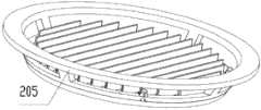
如图3、图4所示,与实施例1不同的是,一种LED灯,包括透光灯盖200、成型透镜的塑胶板201、PCB板202、散热基座203、LED发光单元、电性连接LED发光单元的布图电路导电层(未示出)、与外部电源和布图电路导电层电性连接的电控装置、灯座205。 As shown in Figure 3 and Figure 4, the difference from Embodiment 1 is that an LED lamp includes a light-transmitting lamp cover 200, a plastic plate 201 forming a lens, a PCB board 202, a heat dissipation base 203, an LED light-emitting unit, an electric The conductive layer of the layout circuit (not shown) that is connected to the LED light emitting unit, the electric control device electrically connected with the external power supply and the conductive layer of the layout circuit, and the
灯座205包括上固定环206和下固定环207,四个连接上固定环206和下固定环207的连接筋208。上固定环206的外径大于下固定环207的外径并向外凸出连接筋208形成将LED灯固定在设定位置的固定凸台,下固定环207的内径小于上固定环206的内径并向内凸出连接筋208形成固定散热基座203的固定凸台209。在透光灯盖200朝向散热基座203的面上设有端部带抵挡部210的固定柱211,在灯座205背离透光灯盖200的面上设有与固定柱211和抵挡部210配合的弹性扣212,设置在灯座205上位于弹性扣212中心位置、大于抵挡部210外径的通孔213。透光灯盖200通过固定柱211和其上的抵挡部210穿过通孔213、抵挡部210抵挡在弹性扣212上将透光灯盖200和灯座205固定。散热基座203固定在下固定环207上。 The
实施例4 Example 4
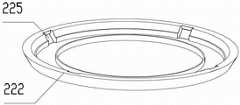
如图5、图6所示,与实施例3不同的是,灯座包括固定环221,从固定环221朝向透光灯盖222的面上延伸设有的连接筋223,在连接筋223的端部设有弹性卡扣224。在透光灯盖222上设有与弹性卡扣224配合的抵挡孔225。透光灯盖222通过弹性卡扣224伸入抵挡孔225并抵挡在透光灯盖222上将 透光灯盖222和灯座固定。散热基座226固定在透光灯盖222上。电控装置(未示出)固定在灯座上。 As shown in Fig. 5 and Fig. 6, the difference from Embodiment 3 is that the lamp holder includes a fixing
实施例5 Example 5
如图7所示,与实施例4不同的是,LED发光单元包括LED芯片230、透镜231、透光封装胶体232、电性连接LED芯片230和布图电路导电层的金线233。透镜231固定在第一通孔234上。透光封装胶体232填充在透镜231和LED芯片230间。 As shown in FIG. 7 , the difference from Embodiment 4 is that the LED light-emitting unit includes an
灯座235、透光灯盖236一体成形。散热基座237固定在透光灯盖236上。 The
Claims (10)
Translated fromChinesePriority Applications (1)
| Application Number | Priority Date | Filing Date | Title |
|---|---|---|---|
| CN2012101490846ACN102691907A (en) | 2011-09-30 | 2012-05-14 | led lights |
Applications Claiming Priority (3)
| Application Number | Priority Date | Filing Date | Title |
|---|---|---|---|
| CN201110300196 | 2011-09-30 | ||
| CN201110300196.2 | 2011-09-30 | ||
| CN2012101490846ACN102691907A (en) | 2011-09-30 | 2012-05-14 | led lights |
Publications (1)
| Publication Number | Publication Date |
|---|---|
| CN102691907Atrue CN102691907A (en) | 2012-09-26 |
Family
ID=46857543
Family Applications (1)
| Application Number | Title | Priority Date | Filing Date |
|---|---|---|---|
| CN2012101490846APendingCN102691907A (en) | 2011-09-30 | 2012-05-14 | led lights |
Country Status (1)
| Country | Link |
|---|---|
| CN (1) | CN102691907A (en) |
Cited By (5)
| Publication number | Priority date | Publication date | Assignee | Title |
|---|---|---|---|---|
| WO2014205613A1 (en)* | 2013-06-28 | 2014-12-31 | 欧普照明股份有限公司 | Connecting apparatus of lighting fixture |
| WO2014205614A1 (en)* | 2013-06-27 | 2014-12-31 | 欧普照明股份有限公司 | Led module with vertical convection heat dissipation structure |
| WO2016041130A1 (en)* | 2014-09-15 | 2016-03-24 | 东莞励国照明有限公司 | Led lamp and manufacturing process therefor |
| CN108730929A (en)* | 2018-07-11 | 2018-11-02 | 南京鹏万达照明有限公司 | A kind of outdoor lamp holder of multi-connection function |
| CN112432110A (en)* | 2020-11-17 | 2021-03-02 | 国网甘肃省电力公司电力科学研究院 | New forms of energy lighting device |
Citations (5)
| Publication number | Priority date | Publication date | Assignee | Title |
|---|---|---|---|---|
| US20070211470A1 (en)* | 2006-03-03 | 2007-09-13 | Hsien-Jung Huang | Lamp house with heat sink |
| CN101598268A (en)* | 2008-06-05 | 2009-12-09 | 先进开发光电股份有限公司 | Photocatalyst lamp |
| TW201002999A (en)* | 2008-07-11 | 2010-01-16 | Foxconn Tech Co Ltd | LED lamp |
| US20100171403A1 (en)* | 2009-01-05 | 2010-07-08 | Fu Zhun Precision Industry (Shen Zhen) Co., Ltd. | Led lamp |
| CN201772362U (en)* | 2010-08-12 | 2011-03-23 | 全昊 | Embedded lamp |
- 2012
- 2012-05-14CNCN2012101490846Apatent/CN102691907A/enactivePending
Patent Citations (5)
| Publication number | Priority date | Publication date | Assignee | Title |
|---|---|---|---|---|
| US20070211470A1 (en)* | 2006-03-03 | 2007-09-13 | Hsien-Jung Huang | Lamp house with heat sink |
| CN101598268A (en)* | 2008-06-05 | 2009-12-09 | 先进开发光电股份有限公司 | Photocatalyst lamp |
| TW201002999A (en)* | 2008-07-11 | 2010-01-16 | Foxconn Tech Co Ltd | LED lamp |
| US20100171403A1 (en)* | 2009-01-05 | 2010-07-08 | Fu Zhun Precision Industry (Shen Zhen) Co., Ltd. | Led lamp |
| CN201772362U (en)* | 2010-08-12 | 2011-03-23 | 全昊 | Embedded lamp |
Cited By (7)
| Publication number | Priority date | Publication date | Assignee | Title |
|---|---|---|---|---|
| WO2014205614A1 (en)* | 2013-06-27 | 2014-12-31 | 欧普照明股份有限公司 | Led module with vertical convection heat dissipation structure |
| WO2014205613A1 (en)* | 2013-06-28 | 2014-12-31 | 欧普照明股份有限公司 | Connecting apparatus of lighting fixture |
| WO2016041130A1 (en)* | 2014-09-15 | 2016-03-24 | 东莞励国照明有限公司 | Led lamp and manufacturing process therefor |
| CN108730929A (en)* | 2018-07-11 | 2018-11-02 | 南京鹏万达照明有限公司 | A kind of outdoor lamp holder of multi-connection function |
| CN108730929B (en)* | 2018-07-11 | 2024-03-08 | 南京鹏万达照明有限公司 | Outdoor lamp stand of many connected functions |
| CN112432110A (en)* | 2020-11-17 | 2021-03-02 | 国网甘肃省电力公司电力科学研究院 | New forms of energy lighting device |
| CN112432110B (en)* | 2020-11-17 | 2022-08-02 | 国网甘肃省电力公司电力科学研究院 | A new energy lighting device |
Similar Documents
| Publication | Publication Date | Title |
|---|---|---|
| CN102691906A (en) | LED lamp | |
| CN101649968B (en) | LED lighting device | |
| CN101368719B (en) | LED lamps | |
| CN102682671B (en) | LED dot matrix display screen and combined dot matrix display screen | |
| RU2418345C1 (en) | Light-emitting diode lamp | |
| CN101413648A (en) | LED light fitting with heat radiation structure | |
| CN103423613A (en) | Light emitting diode lamp | |
| CN101936472A (en) | Bulb-shaped lamps and lighting fixtures | |
| WO2008138177A1 (en) | An led lighting fixture with high-efficiency radiation effect | |
| KR101072584B1 (en) | LED lighting device | |
| CN102691908A (en) | led light | |
| CN101900271A (en) | Light-emitting diode lamps with better heat dissipation effect | |
| CN202834815U (en) | A kind of LED light | |
| CN102691907A (en) | led lights | |
| CN201954316U (en) | LED lamp | |
| CN201273472Y (en) | Improved LED lamp structure | |
| CN103335254A (en) | LED (Light Emitting Diode) light source module and LED streetlamp using same | |
| CN101788112A (en) | Three-dimensional heat dissipation high-power LED illumination device | |
| WO2013086795A1 (en) | Novel common lighting led lamp | |
| CN201555069U (en) | Efficient heat-dissipation type LED lamp | |
| KR100945459B1 (en) | A heat dissipating device of led lamp | |
| TW201314121A (en) | LED lamp | |
| KR20120028534A (en) | Led lamp provided an improved capability of discharging heat | |
| KR100864585B1 (en) | Lamp structure using light emitting diode | |
| CN201739908U (en) | LED projection lamp |
Legal Events
| Date | Code | Title | Description |
|---|---|---|---|
| C06 | Publication | ||
| PB01 | Publication | ||
| C10 | Entry into substantive examination | ||
| SE01 | Entry into force of request for substantive examination | ||
| C02 | Deemed withdrawal of patent application after publication (patent law 2001) | ||
| WD01 | Invention patent application deemed withdrawn after publication | Application publication date:20120926 |