CN102682784A - Method and system for providing a side shield for a perpendicular magnetic recording pole - Google Patents
Method and system for providing a side shield for a perpendicular magnetic recording poleDownload PDFInfo
- Publication number
- CN102682784A CN102682784ACN2012100713527ACN201210071352ACN102682784ACN 102682784 ACN102682784 ACN 102682784ACN 2012100713527 ACN2012100713527 ACN 2012100713527ACN 201210071352 ACN201210071352 ACN 201210071352ACN 102682784 ACN102682784 ACN 102682784A
- Authority
- CN
- China
- Prior art keywords
- layer
- magnetic pole
- magnetic
- antireflective coating
- shield
- Prior art date
- Legal status (The legal status is an assumption and is not a legal conclusion. Google has not performed a legal analysis and makes no representation as to the accuracy of the status listed.)
- Pending
Links
- 230000005291magnetic effectEffects0.000titleclaimsabstractdescription102
- 238000000034methodMethods0.000titleclaimsabstractdescription53
- 239000006117anti-reflective coatingSubstances0.000claimsabstractdescription19
- 239000007788liquidSubstances0.000claimsdescription16
- 238000001259photo etchingMethods0.000claimsdescription10
- 238000000151depositionMethods0.000claimsdescription9
- 230000008021depositionEffects0.000claimsdescription7
- 230000000903blocking effectEffects0.000claimsdescription6
- 238000004528spin coatingMethods0.000claimsdescription4
- 229920002120photoresistant polymerPolymers0.000description19
- 238000010586diagramMethods0.000description13
- XEEYBQQBJWHFJM-UHFFFAOYSA-NIronChemical compound[Fe]XEEYBQQBJWHFJM-UHFFFAOYSA-N0.000description8
- 230000011514reflexEffects0.000description8
- 239000000463materialSubstances0.000description7
- 238000007747platingMethods0.000description7
- 238000007796conventional methodMethods0.000description6
- 238000005260corrosionMethods0.000description5
- 230000007797corrosionEffects0.000description5
- 230000015572biosynthetic processEffects0.000description4
- 229910052742ironInorganic materials0.000description4
- 238000005498polishingMethods0.000description4
- 229910001030Iron–nickel alloyInorganic materials0.000description3
- 239000013078crystalSubstances0.000description3
- 206010070834SensitisationDiseases0.000description2
- PNEYBMLMFCGWSK-UHFFFAOYSA-Naluminium oxideInorganic materials[O-2].[O-2].[O-2].[Al+3].[Al+3]PNEYBMLMFCGWSK-UHFFFAOYSA-N0.000description2
- 238000005229chemical vapour depositionMethods0.000description2
- 238000005516engineering processMethods0.000description2
- 238000005530etchingMethods0.000description2
- 239000000696magnetic materialSubstances0.000description2
- 238000004519manufacturing processMethods0.000description2
- 238000000059patterningMethods0.000description2
- 230000008313sensitizationEffects0.000description2
- 238000000926separation methodMethods0.000description2
- KJTLSVCANCCWHF-UHFFFAOYSA-NRutheniumChemical compound[Ru]KJTLSVCANCCWHF-UHFFFAOYSA-N0.000description1
- 230000004888barrier functionEffects0.000description1
- 230000001066destructive effectEffects0.000description1
- 230000005294ferromagnetic effectEffects0.000description1
- 230000005389magnetismEffects0.000description1
- 229910052707rutheniumInorganic materials0.000description1
- 238000005507sprayingMethods0.000description1
- 239000000758substrateSubstances0.000description1
Images


Classifications
- G—PHYSICS
- G11—INFORMATION STORAGE
- G11B—INFORMATION STORAGE BASED ON RELATIVE MOVEMENT BETWEEN RECORD CARRIER AND TRANSDUCER
- G11B5/00—Recording by magnetisation or demagnetisation of a record carrier; Reproducing by magnetic means; Record carriers therefor
- G11B5/127—Structure or manufacture of heads, e.g. inductive
- G11B5/31—Structure or manufacture of heads, e.g. inductive using thin films
- G11B5/3109—Details
- G11B5/3116—Shaping of layers, poles or gaps for improving the form of the electrical signal transduced, e.g. for shielding, contour effect, equalizing, side flux fringing, cross talk reduction between heads or between heads and information tracks
- G—PHYSICS
- G11—INFORMATION STORAGE
- G11B—INFORMATION STORAGE BASED ON RELATIVE MOVEMENT BETWEEN RECORD CARRIER AND TRANSDUCER
- G11B5/00—Recording by magnetisation or demagnetisation of a record carrier; Reproducing by magnetic means; Record carriers therefor
- G11B5/127—Structure or manufacture of heads, e.g. inductive
- G11B5/31—Structure or manufacture of heads, e.g. inductive using thin films
- G11B5/3109—Details
- G11B5/313—Disposition of layers
- G11B5/3143—Disposition of layers including additional layers for improving the electromagnetic transducing properties of the basic structure, e.g. for flux coupling, guiding or shielding
- G11B5/3146—Disposition of layers including additional layers for improving the electromagnetic transducing properties of the basic structure, e.g. for flux coupling, guiding or shielding magnetic layers
- G11B5/315—Shield layers on both sides of the main pole, e.g. in perpendicular magnetic heads
- G—PHYSICS
- G11—INFORMATION STORAGE
- G11B—INFORMATION STORAGE BASED ON RELATIVE MOVEMENT BETWEEN RECORD CARRIER AND TRANSDUCER
- G11B5/00—Recording by magnetisation or demagnetisation of a record carrier; Reproducing by magnetic means; Record carriers therefor
- G11B5/127—Structure or manufacture of heads, e.g. inductive
- G11B5/31—Structure or manufacture of heads, e.g. inductive using thin films
- G11B5/3163—Fabrication methods or processes specially adapted for a particular head structure, e.g. using base layers for electroplating, using functional layers for masking, using energy or particle beams for shaping the structure or modifying the properties of the basic layers
Landscapes
- Engineering & Computer Science (AREA)
- Manufacturing & Machinery (AREA)
- Physics & Mathematics (AREA)
- Electromagnetism (AREA)
- Magnetic Heads (AREA)
Abstract
Description
Technical field
Background technology
Fig. 1 is the process flow diagram that theconventional method 10 that is used to make conventional perpendicular magnetic recording (PMR) transducer is shown.For simplicity, omit some steps.Conventional method 10 is used at alumina layer PMR being provided magnetic pole.In alumina layer, form groove via step 12.The top of groove is wideer than channel bottom.The top surface of the PMR magnetic pole that therefore, forms therein will be wideer than its bottom.Therefore, the sidewall of PMR magnetic pole will have reflex angle.The bottom of groove also can tilt, thereby the leading edge inclined-plane is provided.Viastep 14 deposit ruthenium (Ru) clearance layer.The Ru clearance layer is used to formside clearance.Step 14 generally includes uses chemical vapor deposition (CVD) deposition Ru clearance layer.Via the conventional PMR pole material ofstep 16plating.Step 16 can comprise plating iron magnetic pole material and crystal seed layer and/or (a plurality of) other layers.Can carry out chemically mechanical polishing (CMP) viastep 18 then, thereby remove excessive (multiple) pole material.Can form top or trailing edge inclined-plane viastep 20 then.Write the gap viastep 22 deposition.Use conventional photoetching process to form conventional photoresist blocking mask via step 24.Then viastep 26 deposition ring around shield.
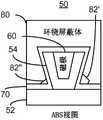
Fig. 2 and 3 illustrates the side view and air bearing surface (ABS) view of the part of theconventional PMR transducer 50 that usesconventional method 10 formation respectively.Conventional transducer 50 during forming shown in Fig. 2.Conventional transducer 50 comprises middle layer 52.Middle layer 52 is the layers that are formed with magnetic pole above that.Also show the employed inclined-plane 53 on the leading edge inclined-plane of expression magnetic pole.Also show photoresist blocking mask 82.The direction of light that is used to form the pattern ofmask 82 is illustrated by the straight arrows among Fig. 2.Conventional PMR transducer after Fig. 3 is illustrated in and completes.Also showRu clearance layer 54, it is deposited in the groove (not shown).Also show conventionalmagnetic pole 60, writegap 70 and top barrier body 80.Therefore, useconventional method 10 can formmagnetic pole 60.
Althoughconventional method 10 can provideconventional PMR transducer 50, possibly there is shortcoming.As shown in Figure 2,photoresist mask 82 can demonstrate recess 84.Recess 84 against corrosion is near the substrate of photoresist mask 82.Therefore, the shield of plating can have the profile of not expecting in the step 26.Further,recess 84 can be uncontrollable, especially in high power capacity technology.Therefore, possibly influence the output and/or the performance ofconventional PMR transducer 50 unfriendly.Further, as finding out among Fig. 3, can exist fromphotoresist mask 82 against corrosion residual 82 ' and 82 ".The reflex angle of (for example the top is wideer than the bottom) conventionalmagnetic pole 60 and relational structure can cause and can not removepart mask 82 against corrosion from the shadow region near the bottom of conventional magnetic pole 60.Therefore, typical organic against corrosion residual 82 ' and 82 " may reside in the last device.This against corrosion residual 82 ' and 82 " occupy expectation and become zone around the part of shield 80.Therefore, performance and/or output can reduce once more.Therefore, needed is the improved method that is used to make the PMR transducer.
Summary of the invention
The invention describes the method that is used to make magnetic transducer with nonmagnetic middle layer.On the middle layer, provide magnetic pole.This magnetic pole has side, bottom, than the wideer top, bottom and the inclined-plane, top of next-door neighbour ABS position.Side clearance is provided as the side of contiguous at least magnetic pole.Bottom antireflective coating (BARC) is provided on the middle layer.Can remove the BARC layer through the use liquid etchant, and the contiguous at least a portion side clearance of this BARC layer.Mask layer is provided on the BARC layer.Pattern is delivered in the mask layer through photoetching, forms blocking mask.The part of BARC layer is exposed to liquid etchant, so that a plurality of sides of magnetic pole and side clearance break away from the BARC layer.At least one side shield is provided.This side shield is a magnetic.
Description of drawings
Fig. 1 shows the process flow diagram of the conventional method that is used to make the PMR transducer.
Fig. 2 shows the diagram of the side view of conventional PMR transducer.
Fig. 3 shows the diagram of the ABS view of conventional PMR transducer.
Fig. 4 shows the process flow diagram of an exemplary embodiment of the method that is used to make the PMR transducer.
Fig. 5 shows the diagram at the side view of an exemplary embodiment of making period P MR transducer.
Fig. 6 shows side view and the diagram of ABS view of an exemplary embodiment of PMR transducer.
Fig. 7 shows the process flow diagram of another exemplary embodiment of the method that is used to make the PMR transducer.
Fig. 8-13 shows the diagram of an exemplary embodiment of magnetic recording transducer during making.
Embodiment
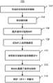
Fig. 4 shows the process flow diagram of the exemplary embodiment of themethod 100 that is used to make transducer.Although other transducers can also be made like this,method 100 has been described in the background of PMR transducer.For the sake of simplicity, can omission, interleave and/or make up some steps.The PMR transducer of made can be a part that merges head (merged head), and this merging head also comprises the read head (not shown) and is arranged on the slide block (not shown) ofdisc driver.Method 100 begins after also can forming in other parts of PMRtransducer.Describing method 100 in the background that single PMR magnetic pole and the relational structure in single magnetic recording transducer thereof are provided also.Yetmethod 100 can be used for basically side by side making a plurality of transducers.Also describingmethod 100 and system in the background of certain layer.Yet in certain embodiments, these layers can comprise a plurality of sublayers.In one embodiment,method 100 begins after (a plurality of) middle layer on it, PMR magnetic pole position forms.In certain embodiments, expectation leading edge shield.In these embodiment, the leading edge shield can be the some or all of of middle layer.The leading edge shield is the ferromagnet of soft magnetism normally, and can comprise for example material such as NiFe.
Viastep 102 magnetic pole is provided on the middle layer.Magnetic pole has side, bottom, than the wideer top, bottom and the front bevel of next-door neighbour ABS position.The ABS position be for example transducer in polishing (lap) the ABS position that will be in afterwards.Front bevel is in the bottom of magnetic pole, and allows to be positioned at the part of the most advanced and sophisticated height of the magnetic pole of ABS less than the magnetic pole of ABS far-end.In certain embodiments,step 102 can be included in and form the inclined-plane in the middle layer, perhaps on the middle layer, deposits and the patterning sublayer, thereby forms the inclined-plane.As used herein, this Seed Layer is considered to the part in middle layer.The inclined-plane that provides in thestep 102 can have at least ten degree and be not more than the angle of 50 degree.In certain embodiments, the angle on said inclined-plane is 30 degree, in process tolerant.The magnetic pole that provides in thestep 102 also can be the PMR magnetic pole.Because the top of magnetic pole is wideer than the bottom, sidewall has reflex angle.In certain embodiments, the reflex angle of magnetic pole sidewall is greater than zero degree and be not more than 20 degree.In other embodiments, reflex angle is approximately seven to nine degree.Part as making magnetic pole can provide (multilayer) crystal seed layer andmagnetosphere.Step 102 can comprise that for example sputter deposits ferromagnetic and other materials through plating perhaps.In certain embodiments,, magnetic pole also can carry out polishing, for example CMP in being provided.In other embodiments, can make magnetic pole in another way.
The non magnetic side clearance of the side of contiguous at least magnetic pole is provided via step 104.In certain embodiments, the part of side clearance places the magnetic pole below.Further, in certain embodiments, instep 102, before the deposition pole material, can in the middle layer, form groove and instep 104, deposit side clearance.
Viastep 106, bottom antireflective coating (BARC) is provided on the middle layer.Can remove the BARC layer through using liquid etchant.Therefore, the BARC layer can be through using suitable liquid etchant liquid etching.BARC is at least a portion in adjacent side gap also.In other words, some BARC layers are positioned at the residing zone of next-door neighbour's side clearance, and in certain embodiments, residing zone, adjacent sides gap.In certain embodiments, the BARC layer can develop.In other words, can use developer to remove the BARC layer.An example of this BARC layer comprises ARC DS-K101.Be described below, the BARC layer also is configured to reduce the reflection of light that uses in the step 108.More specifically, can repair the thickness of BARC layer, make and reflect the light experience destructive interference of leaving the layer that is lower than the BARC layer with being right after.Therefore, the reflection from lower floor can be reduced or remove basically.
Viastep 108, on the BARC layer, mask layer is provided.Mask layer be sensitization and can use photoetching process to form pattern.For example, mask layer can comprise the photoresist of some types.Viastep 110, be delivered in the mask layer through photoetching after the pattern, formblocking mask.Step 110 can comprise a part of photoresist layer is exposed to light, then transducer is exposed to developer, and this developer is removed the photoresist that exposes.In certain embodiments, identical developer that can liquid etching BARC layer also is used to make mask layer photoetching ground to form pattern.
Viastep 112, a part of BARC layer is exposed to liquid etchant, and it removes the BARC layer.Therefore, the expose portion of BARC layer is removed.More particularly, the side and the side clearance of the magnetic pole of BARC layer vicinity break away from the BARC layer now.In the embodiment that BARC can develop, the part thatstep 112 can be used asstep 110 is performed.For example, the developer that is used forstep 110 can be that the BARC layer can the etched developer of enough its liquid.In this embodiment, the removal of the resist of exposure can be carried out with the removal of the BARC layer that can develop together.
Viastep 114, the side shield is provided at least.In certain embodiments, instep 114, provide loopful around shield.In this embodiment, be desirably in making around depositing the top clearance before the shield.In other embodiments, can in separation steps, make back shield (trailing shield).The shield that instep 114, provides is a magnetic.Therefore,step 114 can comprise plating or deposited iron magnetic soft magnetic material, for example NiFe.
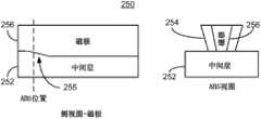
Fig. 5-the 6th, illustrate can method of application the diagram of an exemplary embodiment of a part of the 100PMR transducers 150 that form.For clear, Fig. 5-6 does not draw in proportion.Fig. 5 shows thetransducer 150 during the formation.The part of showntransducer 150 is at the magnetic pole far-end, and the side shield can form herein.Therefore, showmiddle layer 152, but magnetic pole is not shown in Fig. 5.Also show inclined-plane 153, it is formed in the middle layer 152.BARC layer 154 covered inclined-plane 153 withmask layer 159 beforestep 110 is carried out.The thickness ofBARC layer 158 can be not more than 100 nanometers.In certain embodiments, the thickness ofBARC layer 158 can be not more than 40 nanometers, in technique change.On the contrary,mask layer 159 can be thick.For example,mask layer 159 can be dark UV photoresist.In this embodiment, the thickness ofmask layer 159 can approximately be 1.5 microns.After having carried out step 110-112, self-masking layer 159forms mask 159 '.Further, BARC layer 158 ' only be positioned at mask 159 ' below because remainder has been exposed to liquid etchant.Fig. 6 is illustrated in thelater transducer 150 of execution in step 114.Exceptmiddle layer 152, also show clearance layer 154.Also show magnetic pole 156, extra clearance layer 160 and shield 162.Magnetic pole 156 has top and the reflex angle θ wideer than its bottom.In an illustrated embodiment, magnetic pole 156 not only comprises the front bevel 155 corresponding tofront bevel 153, but also comprises optional back bevel 157.In certain embodiments, the thickness of front bevel 155 is about 200 nanometers, and the thickness of magnetic pole 156 is about 300 nanometers.Therefore, inclined-plane 155 and 157 can occupy most of height of magnetic pole 156.
Method ofapplication 100 can be improved the making of PMR transducer.Like what in Fig. 5-6, can find out, mask 159 ' breaks away from recess basically.The existence ofBARC layer 158 can allow to reduce from the inclined-plane 153 reflection.Although not shown,, can there be little undercutting owing to excessively removeBARC layer 158 '.Yet, to compare with the height ofmask 159,BARC layer 158 is little.Further, this undercutting can monitored and control during high power capacity is made.Further, like what in Fig. 6, can find out, there are not to come self-masking layer 159 or residual from BARClayer 158 basically.This is because BARClayer 158 can be removed through using liquid etchant.Therefore, shield 162 has the profile of expectation.Therefore, can improve the manufacturing and the performance oftransducer 150.
Fig. 7 is the process flow diagram that another exemplary embodiment of the method 200 that is used to make the PMR transducer is shown.For simplicity, can omit some steps.Fig. 8-the 13rd is illustrated in side view and the diagram of ABS view of the exemplary embodiment of a part of making period P MR transducer 250.For clear, Fig. 8-13 does not draw in proportion.For side view, the magnetic pole view among Fig. 8-13 obtains in the centre position that forms magnetic pole, and view contiguous magnetic pole in inclined-plane obtains, the formation side at said magnetic pole place/and around shield.Further, although Fig. 8-13 shows the ABS at ABS position (will form the position of ABS) and the specified point place in magnetic pole, other embodiment also can have other ABS positions.With reference to figure 8-13, method 200 is described in the background of PMR transducer 250.Yet method 200 can be used to form another kind of device (not shown).ThePMR transducer 250 of made can be a part that merges head, and this merging head also comprises read head (not shown in Fig. 8-13) and places on the slide block (not shown) of disc driver.Said method 200 begins after also can forming in other parts of PMR transducer 250.Said method 200 is also described in the background thatsingle PMR transducer 250 is provided.Yet said method 200 can be used for basically side by side making a plurality of transducers.Said method 200 is also described in the background of certain layer with device 250.Yet in certain embodiments, these layers can comprise a plurality of sublayers.
Via step 202 the PMR magnetic pole is provided on the middle layer.Step 202 is similar to thestep 102 of method 100.Therefore, step 202 can comprise formation front bevel and deposition (a plurality of) crystal seed layer, (a plurality of) magnetosphere and/or (a plurality of) other optional layers.In certain embodiments, step 202 can be included in and form the inclined-plane in the middle layer or on the middle layer, deposit also patterning sublayer, thereby forms the inclined-plane.Step 202 for example can comprise comes deposited iron magnet and other materials via plating or sputter.In certain embodiments,, magnetic pole also can carry out polishing, for example CMP in being provided.In other embodiments, can make magnetic pole in another way.Also the trailing edge inclined-plane can be provided.
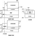
Via the non magnetic side clearance of step 204 deposition.In certain embodiments, step 204 can be carried out before the PMR magnetic pole is provided.In these embodiment, a part of side clearance is lower than the PMR magnetic pole.Fig. 8 shows thelater transducer 250 of execution in step 204.Showmagnetic pole 256middle layer 252 placed on it.Also show gap 254.In an illustrated embodiment, onmiddle layer 252, magnetic pole is provided.Yet in other embodiments, magnetic pole can place on the part of clearance layer 254.Magnetic pole 256 has side, bottom, than the wideer top, bottom and thefront bevel 255 of next-door neighbour ABS position.Although back bevel is not shown, in other embodiments, can comprise this inclined-plane.In certain embodiments, the reflex angle of sidewall is greater than zero degree and be not more than 20 degree.In other embodiments, reflex angle is approximately seven to nine degree.Inclined-plane 255 can have at least ten degree and be not more than the angle of 50 degree.In some this embodiment, the angle on inclined-plane 255 is 30 degree, in processtolerant.Transducer 250 can comprise preceding shield (not shown).In this embodiment,middle layer 252 can be preceding shield, and a part or other nonmagnetic layers ofclearance layer 254 will place betweenmagnetic pole 256 and themiddle layer 252.
Via step 206, bottom antireflective coating (BARC) spin coating on the middle layer.The BARC layer can be removed through using liquid etchant.More specifically, the BARC layer of spraying is the BARC that can develop in step 206, for example ARC DS-K101.BARC is at least a portion in adjacent side gap also.In other words, some BARC layers are positioned at and are right after the residing zone of side clearance, and in certain embodiments, more said residing zones, BARC layer adjacent sides gap.Be described below, the BARC layer also is configured to reduce employed reflection of light in the step 212.
Via step 208, spin coating photoresist mask layer on the BARC layer.The photoresist mask layer be sensitization and can form pattern through using photoetching process.Fig. 9 shows the later transducer of execution in step 208.In addition, show the side view of inclined-plane and magnetic pole.Therefore, show to develop BARC (D-BARC)layer 260 and photoresist layer 262.Although be described as having similar thickness, in certain embodiments, D-BARC layer 260 can be obviously thinner thanphotoresist 262.
Via step 210, the part mask layer is exposed to the light of appropriate frequency, thereby pattern is delivered to mask layer.Via step 212,transducer 250 is exposed to and is used for photolithographic developer.Developer is removed the part thatphotoresist layer 262 has been exposed to light.In addition, because removed partphotoresist layer 262, so following D-BARC layer 260 also can be exposed to developer.Therefore, also remove these parts of D-BARC layer 260.Figure 10 shows thelater transducer 250 of execution in step 214.Removed the part of D-BARC layer 260 and photoresist layer 262.Therefore, the remainder of D-BARC 260 ' and photoresist 262 ' forms shield mask.Like what can find out among Figure 10, be exposed to the arbitrary portion that developer has been removed D-BARC layer 260, and the arbitrary portion of D-BARC layer 260 is removed from a plurality of sides of PMRmagnetic pole 256 and side clearance 254.Further, photoresist mask 262 ' and implement this removal of D-BARC 260 is provided with having combined photoetching.
Via step 214, side shield at least is provided.In certain embodiments, in step 214, provide loopful around shield.In these embodiment, be desirably in making around depositing the top clearance before the shield.In other embodiments, can in separation steps, make the back shield.Step 216 can comprise plating or deposited iron magnetic soft magnetic material, for example NiFe.Figure 11 illustrates thelater transducer 250 of execution in step 216.Therefore,shield 264 has been deposited.If the side shield only is provided, the part ofshield 264 onmagnetic pole 256 can be removed so.Ifshield 264 is around shield, the non-magnetic gap (not shown) will be present between the top andshield 264 ofmagnetic pole 256 at least so.
Via step 216, on PMRmagnetic pole 256, deposit the non-magnetic gap layer at least.In certain embodiments, can be in execution in step 216 before the step 206.Figure 12 illustrates thetransducer 250 after the step 216.Therefore,writing gap 266 illustrates on magnetic pole 256.Via step 220, the magnetic top shield can optionally be provided.Figure 13 illustrates thetransducer 250 after the execution in step 220.Therefore,back shield 268 is provided.Therefore,shield
Therefore, through method of application 200, can make PMR transducer 250.PMR transducer 250 has the geometric configuration of expectation.Especially,shield 264/268 has the surface configuration of expectation.In addition, transducer can break away from residual from D-BARC 260 and photoresist 262.Therefore, can improve the manufacturing and the performance oftransducer 250.
Claims (13)
1. method that is used to make magnetic transducer with middle layer and air bearing surface ABS, said method comprises:
On said middle layer, magnetic pole is provided, said magnetic pole has a plurality of sides, bottom, than the wideer top, said bottom and the front bevel of next-door neighbour ABS position;
The side clearance of a plurality of at least sides of contiguous said magnetic pole is provided;
Bottom antireflective coating BARC is provided on said middle layer, and said bottom antireflective coating can be through using at least a portion of liquid etchant removal and contiguous said side clearance;
On said bottom antireflective coating, mask layer is provided;
Photoetching ground transmits pattern in said mask layer, forms blocking mask;
The said bottom antireflective coating of a part is exposed to said liquid etchant, so that a plurality of sides of said magnetic pole and said side clearance break away from said bottom antireflective coating;
The side shield is provided at least, and said side shield is a magnetic.
2. method according to claim 1 further comprises:
On said at least magnetic pole and said side clearance, deposit clearance layer.
3. method according to claim 2, the wherein said step of side shield that provides at least comprises:
The magnetic top shield is provided.
4. method according to claim 1, wherein said bottom antireflective coating can develop.
5. method according to claim 4, wherein said bottom antireflective coating comprises ARCDS-K101.
6. method according to claim 4, wherein said liquid etchant is a developer.
7. method according to claim 6, the step that wherein said photoetching ground transmits pattern further comprises:
The part of said mask layer is exposed to light; With
Use said developer to remove the said part of said mask layer.
8. method according to claim 6, the wherein said step that said bottom antireflective coating is exposed to said liquid etchant transmit as said photoetching ground pattern step a part and carry out.
9. method according to claim 2, the thickness of wherein said bottom antireflective coating is not more than 100 nanometers.
10. method according to claim 1, the wherein said step of side shield layer that provides at least further comprises:
Plate at least one shield layer.
11. method according to claim 1, wherein said magnetic pole are that perpendicular magnetic recording writes magnetic pole.
12. being exposed to the part of said liquid etchant, method according to claim 1, wherein said bottom antireflective coating do not covered by said shield mask.
13. a method that is used to make perpendicular magnetic recording PMR transducer, said PMR transducer has middle layer and air bearing surface ABS, and said method comprises:
On said middle layer, PMR is provided magnetic pole, said PMR magnetic pole has a plurality of sides, bottom, than the wideer top, said bottom and the front bevel of next-door neighbour ABS position;
The side clearance of a plurality of at least sides of contiguous said magnetic pole is provided, and said side clearance is non magnetic;
The bottom antireflective coating BARC that spin coating can be developed on said middle layer, the said bottom antireflective coating that develops can be through using the developer removal and having the thickness that is not more than 100 nanometers;
Spin coating mask layer on said bottom antireflective coating;
The part of said mask layer is exposed to light;
Said transducer is exposed to said developer; The said part of said mask layer and a part of said bottom antireflective coating are removed by said developer, the arbitrary portion that forms blocking mask and remove said bottom antireflective coating from a plurality of sides and the said side clearance layer of said PMR magnetic pole;
The magnetic side shield is provided;
Deposition non-magnetic gap layer on said at least PMR magnetic pole and said side clearance; With
The magnetic top shield is provided, and said non-magnetic gap is placed between said PMR magnetic pole and the said magnetic top shield.
Applications Claiming Priority (2)
| Application Number | Priority Date | Filing Date | Title |
|---|---|---|---|
| US13/051,884 | 2011-03-18 | ||
| US13/051,884US20120237878A1 (en) | 2011-03-18 | 2011-03-18 | Method and system for providing a side shield for a perpendicular magnetic recording pole |
Publications (1)
| Publication Number | Publication Date |
|---|---|
| CN102682784Atrue CN102682784A (en) | 2012-09-19 |
Family
ID=46814593
Family Applications (1)
| Application Number | Title | Priority Date | Filing Date |
|---|---|---|---|
| CN2012100713527APendingCN102682784A (en) | 2011-03-18 | 2012-03-16 | Method and system for providing a side shield for a perpendicular magnetic recording pole |
Country Status (2)
| Country | Link |
|---|---|
| US (1) | US20120237878A1 (en) |
| CN (1) | CN102682784A (en) |
Families Citing this family (133)
| Publication number | Priority date | Publication date | Assignee | Title |
|---|---|---|---|---|
| US8689430B1 (en) | 2006-11-29 | 2014-04-08 | Western Digital (Fremont), Llc | Method for providing a perpendicular magnetic recording (PMR)head |
| US8404128B1 (en) | 2009-02-23 | 2013-03-26 | Western Digital (Fremont), Llc | Method and system for providing a perpendicular magnetic recording head |
| US8400731B1 (en) | 2009-04-19 | 2013-03-19 | Western Digital (Fremont), Llc | Write head with variable side shield gaps |
| US8611055B1 (en) | 2009-07-31 | 2013-12-17 | Western Digital (Fremont), Llc | Magnetic etch-stop layer for magnetoresistive read heads |
| US9202480B2 (en) | 2009-10-14 | 2015-12-01 | Western Digital (Fremont), LLC. | Double patterning hard mask for damascene perpendicular magnetic recording (PMR) writer |
| US8441896B2 (en) | 2010-06-25 | 2013-05-14 | Western Digital (Fremont), Llc | Energy assisted magnetic recording head having laser integrated mounted to slider |
| US8997832B1 (en) | 2010-11-23 | 2015-04-07 | Western Digital (Fremont), Llc | Method of fabricating micrometer scale components |
| US8441756B1 (en) | 2010-12-16 | 2013-05-14 | Western Digital (Fremont), Llc | Method and system for providing an antiferromagnetically coupled writer |
| US9123359B1 (en) | 2010-12-22 | 2015-09-01 | Western Digital (Fremont), Llc | Magnetic recording transducer with sputtered antiferromagnetic coupling trilayer between plated ferromagnetic shields and method of fabrication |
| US8456961B1 (en) | 2011-03-22 | 2013-06-04 | Western Digital (Fremont), Llc | Systems and methods for mounting and aligning a laser in an electrically assisted magnetic recording assembly |
| US8419954B1 (en) | 2011-10-31 | 2013-04-16 | Western Digital (Fremont), Llc | Method for providing a side shield for a magnetic recording transducer |
| US8451563B1 (en) | 2011-12-20 | 2013-05-28 | Western Digital (Fremont), Llc | Method for providing a side shield for a magnetic recording transducer using an air bridge |
| US8760823B1 (en) | 2011-12-20 | 2014-06-24 | Western Digital (Fremont), Llc | Method and system for providing a read transducer having soft and hard magnetic bias structures |
| US9093639B2 (en) | 2012-02-21 | 2015-07-28 | Western Digital (Fremont), Llc | Methods for manufacturing a magnetoresistive structure utilizing heating and cooling |
| US8703397B1 (en) | 2012-03-29 | 2014-04-22 | Western Digital (Fremont), Llc | Method for providing side shields for a magnetic recording transducer |
| US9349392B1 (en) | 2012-05-24 | 2016-05-24 | Western Digital (Fremont), Llc | Methods for improving adhesion on dielectric substrates |
| US8724259B1 (en) | 2012-06-11 | 2014-05-13 | Western Digital (Fremont), Llc | Conformal high moment side shield seed layer for perpendicular magnetic recording writer |
| US8830624B2 (en)* | 2012-06-26 | 2014-09-09 | Seagate Technology Llc | Write pole for recording head |
| US8711528B1 (en) | 2012-06-29 | 2014-04-29 | Western Digital (Fremont), Llc | Tunnel magnetoresistance read head with narrow shield-to-shield spacing |
| US9269382B1 (en) | 2012-06-29 | 2016-02-23 | Western Digital (Fremont), Llc | Method and system for providing a read transducer having improved pinning of the pinned layer at higher recording densities |
| US9213322B1 (en) | 2012-08-16 | 2015-12-15 | Western Digital (Fremont), Llc | Methods for providing run to run process control using a dynamic tuner |
| US8984740B1 (en) | 2012-11-30 | 2015-03-24 | Western Digital (Fremont), Llc | Process for providing a magnetic recording transducer having a smooth magnetic seed layer |
| US9053719B2 (en) | 2012-11-30 | 2015-06-09 | Western Digital (Fremont), Llc | Magnetoresistive sensor for a magnetic storage system read head, and fabrication method thereof |
| US8980109B1 (en) | 2012-12-11 | 2015-03-17 | Western Digital (Fremont), Llc | Method for providing a magnetic recording transducer using a combined main pole and side shield CMP for a wraparound shield scheme |
| US8760818B1 (en) | 2013-01-09 | 2014-06-24 | Western Digital (Fremont), Llc | Systems and methods for providing magnetic storage elements with high magneto-resistance using heusler alloys |
| US9042208B1 (en) | 2013-03-11 | 2015-05-26 | Western Digital Technologies, Inc. | Disk drive measuring fly height by applying a bias voltage to an electrically insulated write component of a head |
| US8883017B1 (en) | 2013-03-12 | 2014-11-11 | Western Digital (Fremont), Llc | Method and system for providing a read transducer having seamless interfaces |
| US9336814B1 (en) | 2013-03-12 | 2016-05-10 | Western Digital (Fremont), Llc | Inverse tapered waveguide for use in a heat assisted magnetic recording head |
| US9013836B1 (en) | 2013-04-02 | 2015-04-21 | Western Digital (Fremont), Llc | Method and system for providing an antiferromagnetically coupled return pole |
| US9111564B1 (en) | 2013-04-02 | 2015-08-18 | Western Digital (Fremont), Llc | Magnetic recording writer having a main pole with multiple flare angles |
| US9104107B1 (en) | 2013-04-03 | 2015-08-11 | Western Digital (Fremont), Llc | DUV photoresist process |
| US8993217B1 (en) | 2013-04-04 | 2015-03-31 | Western Digital (Fremont), Llc | Double exposure technique for high resolution disk imaging |
| US9064527B1 (en) | 2013-04-12 | 2015-06-23 | Western Digital (Fremont), Llc | High order tapered waveguide for use in a heat assisted magnetic recording head |
| US9070381B1 (en) | 2013-04-12 | 2015-06-30 | Western Digital (Fremont), Llc | Magnetic recording read transducer having a laminated free layer |
| US9245545B1 (en) | 2013-04-12 | 2016-01-26 | Wester Digital (Fremont), Llc | Short yoke length coils for magnetic heads in disk drives |
| US9431047B1 (en) | 2013-05-01 | 2016-08-30 | Western Digital (Fremont), Llc | Method for providing an improved AFM reader shield |
| US9064528B1 (en) | 2013-05-17 | 2015-06-23 | Western Digital Technologies, Inc. | Interferometric waveguide usable in shingled heat assisted magnetic recording in the absence of a near-field transducer |
| US9431039B1 (en) | 2013-05-21 | 2016-08-30 | Western Digital (Fremont), Llc | Multiple sensor array usable in two-dimensional magnetic recording |
| US9263067B1 (en) | 2013-05-29 | 2016-02-16 | Western Digital (Fremont), Llc | Process for making PMR writer with constant side wall angle |
| US9361913B1 (en) | 2013-06-03 | 2016-06-07 | Western Digital (Fremont), Llc | Recording read heads with a multi-layer AFM layer methods and apparatuses |
| US9406331B1 (en) | 2013-06-17 | 2016-08-02 | Western Digital (Fremont), Llc | Method for making ultra-narrow read sensor and read transducer device resulting therefrom |
| US9287494B1 (en) | 2013-06-28 | 2016-03-15 | Western Digital (Fremont), Llc | Magnetic tunnel junction (MTJ) with a magnesium oxide tunnel barrier |
| US9318130B1 (en) | 2013-07-02 | 2016-04-19 | Western Digital (Fremont), Llc | Method to fabricate tunneling magnetic recording heads with extended pinned layer |
| US8923102B1 (en) | 2013-07-16 | 2014-12-30 | Western Digital (Fremont), Llc | Optical grating coupling for interferometric waveguides in heat assisted magnetic recording heads |
| US8947985B1 (en) | 2013-07-16 | 2015-02-03 | Western Digital (Fremont), Llc | Heat assisted magnetic recording transducers having a recessed pole |
| US9431032B1 (en) | 2013-08-14 | 2016-08-30 | Western Digital (Fremont), Llc | Electrical connection arrangement for a multiple sensor array usable in two-dimensional magnetic recording |
| US9275657B1 (en) | 2013-08-14 | 2016-03-01 | Western Digital (Fremont), Llc | Process for making PMR writer with non-conformal side gaps |
| US9042051B2 (en) | 2013-08-15 | 2015-05-26 | Western Digital (Fremont), Llc | Gradient write gap for perpendicular magnetic recording writer |
| US9343098B1 (en) | 2013-08-23 | 2016-05-17 | Western Digital (Fremont), Llc | Method for providing a heat assisted magnetic recording transducer having protective pads |
| US9343086B1 (en) | 2013-09-11 | 2016-05-17 | Western Digital (Fremont), Llc | Magnetic recording write transducer having an improved sidewall angle profile |
| US9441938B1 (en) | 2013-10-08 | 2016-09-13 | Western Digital (Fremont), Llc | Test structures for measuring near field transducer disc length |
| US9042058B1 (en) | 2013-10-17 | 2015-05-26 | Western Digital Technologies, Inc. | Shield designed for middle shields in a multiple sensor array |
| US9349394B1 (en) | 2013-10-18 | 2016-05-24 | Western Digital (Fremont), Llc | Method for fabricating a magnetic writer having a gradient side gap |
| US9007719B1 (en) | 2013-10-23 | 2015-04-14 | Western Digital (Fremont), Llc | Systems and methods for using double mask techniques to achieve very small features |
| US9214172B2 (en) | 2013-10-23 | 2015-12-15 | Western Digital (Fremont), Llc | Method of manufacturing a magnetic read head |
| US8988812B1 (en) | 2013-11-27 | 2015-03-24 | Western Digital (Fremont), Llc | Multi-sensor array configuration for a two-dimensional magnetic recording (TDMR) operation |
| US9194692B1 (en) | 2013-12-06 | 2015-11-24 | Western Digital (Fremont), Llc | Systems and methods for using white light interferometry to measure undercut of a bi-layer structure |
| US9280990B1 (en) | 2013-12-11 | 2016-03-08 | Western Digital (Fremont), Llc | Method for fabricating a magnetic writer using multiple etches |
| US9001628B1 (en) | 2013-12-16 | 2015-04-07 | Western Digital (Fremont), Llc | Assistant waveguides for evaluating main waveguide coupling efficiency and diode laser alignment tolerances for hard disk |
| US8917581B1 (en) | 2013-12-18 | 2014-12-23 | Western Digital Technologies, Inc. | Self-anneal process for a near field transducer and chimney in a hard disk drive assembly |
| US9082423B1 (en) | 2013-12-18 | 2015-07-14 | Western Digital (Fremont), Llc | Magnetic recording write transducer having an improved trailing surface profile |
| US9147408B1 (en) | 2013-12-19 | 2015-09-29 | Western Digital (Fremont), Llc | Heated AFM layer deposition and cooling process for TMR magnetic recording sensor with high pinning field |
| US8971160B1 (en) | 2013-12-19 | 2015-03-03 | Western Digital (Fremont), Llc | Near field transducer with high refractive index pin for heat assisted magnetic recording |
| US8970988B1 (en) | 2013-12-31 | 2015-03-03 | Western Digital (Fremont), Llc | Electric gaps and method for making electric gaps for multiple sensor arrays |
| US9305583B1 (en) | 2014-02-18 | 2016-04-05 | Western Digital (Fremont), Llc | Method for fabricating a magnetic writer using multiple etches of damascene materials |
| US9183854B2 (en) | 2014-02-24 | 2015-11-10 | Western Digital (Fremont), Llc | Method to make interferometric taper waveguide for HAMR light delivery |
| US9202493B1 (en) | 2014-02-28 | 2015-12-01 | Western Digital (Fremont), Llc | Method of making an ultra-sharp tip mode converter for a HAMR head |
| US8988825B1 (en) | 2014-02-28 | 2015-03-24 | Western Digital (Fremont, LLC | Method for fabricating a magnetic writer having half-side shields |
| US9396743B1 (en) | 2014-02-28 | 2016-07-19 | Western Digital (Fremont), Llc | Systems and methods for controlling soft bias thickness for tunnel magnetoresistance readers |
| US9142233B1 (en) | 2014-02-28 | 2015-09-22 | Western Digital (Fremont), Llc | Heat assisted magnetic recording writer having a recessed pole |
| US9001467B1 (en) | 2014-03-05 | 2015-04-07 | Western Digital (Fremont), Llc | Method for fabricating side shields in a magnetic writer |
| US9153255B1 (en) | 2014-03-05 | 2015-10-06 | Western Digital (Fremont), Llc | Method for fabricating a magnetic writer having an asymmetric gap and shields |
| US9135930B1 (en) | 2014-03-06 | 2015-09-15 | Western Digital (Fremont), Llc | Method for fabricating a magnetic write pole using vacuum deposition |
| US9934811B1 (en) | 2014-03-07 | 2018-04-03 | Western Digital (Fremont), Llc | Methods for controlling stray fields of magnetic features using magneto-elastic anisotropy |
| US9190085B1 (en) | 2014-03-12 | 2015-11-17 | Western Digital (Fremont), Llc | Waveguide with reflective grating for localized energy intensity |
| US9111558B1 (en) | 2014-03-14 | 2015-08-18 | Western Digital (Fremont), Llc | System and method of diffractive focusing of light in a waveguide |
| US9135937B1 (en) | 2014-05-09 | 2015-09-15 | Western Digital (Fremont), Llc | Current modulation on laser diode for energy assisted magnetic recording transducer |
| US8976635B1 (en) | 2014-06-10 | 2015-03-10 | Western Digital (Fremont), Llc | Near field transducer driven by a transverse electric waveguide for energy assisted magnetic recording |
| US8958272B1 (en) | 2014-06-10 | 2015-02-17 | Western Digital (Fremont), Llc | Interfering near field transducer for energy assisted magnetic recording |
| US9007879B1 (en) | 2014-06-10 | 2015-04-14 | Western Digital (Fremont), Llc | Interfering near field transducer having a wide metal bar feature for energy assisted magnetic recording |
| US8953422B1 (en) | 2014-06-10 | 2015-02-10 | Western Digital (Fremont), Llc | Near field transducer using dielectric waveguide core with fine ridge feature |
| US9508363B1 (en) | 2014-06-17 | 2016-11-29 | Western Digital (Fremont), Llc | Method for fabricating a magnetic write pole having a leading edge bevel |
| US9361914B1 (en) | 2014-06-18 | 2016-06-07 | Western Digital (Fremont), Llc | Magnetic sensor with thin capping layer |
| US9053735B1 (en) | 2014-06-20 | 2015-06-09 | Western Digital (Fremont), Llc | Method for fabricating a magnetic writer using a full-film metal planarization |
| US9214169B1 (en) | 2014-06-20 | 2015-12-15 | Western Digital (Fremont), Llc | Magnetic recording read transducer having a laminated free layer |
| US9042052B1 (en) | 2014-06-23 | 2015-05-26 | Western Digital (Fremont), Llc | Magnetic writer having a partially shunted coil |
| US9230565B1 (en) | 2014-06-24 | 2016-01-05 | Western Digital (Fremont), Llc | Magnetic shield for magnetic recording head |
| US9190079B1 (en) | 2014-09-22 | 2015-11-17 | Western Digital (Fremont), Llc | Magnetic write pole having engineered radius of curvature and chisel angle profiles |
| US9007725B1 (en) | 2014-10-07 | 2015-04-14 | Western Digital (Fremont), Llc | Sensor with positive coupling between dual ferromagnetic free layer laminates |
| US9087527B1 (en) | 2014-10-28 | 2015-07-21 | Western Digital (Fremont), Llc | Apparatus and method for middle shield connection in magnetic recording transducers |
| US9786301B1 (en) | 2014-12-02 | 2017-10-10 | Western Digital (Fremont), Llc | Apparatuses and methods for providing thin shields in a multiple sensor array |
| US9111550B1 (en) | 2014-12-04 | 2015-08-18 | Western Digital (Fremont), Llc | Write transducer having a magnetic buffer layer spaced between a side shield and a write pole by non-magnetic layers |
| US9721595B1 (en) | 2014-12-04 | 2017-08-01 | Western Digital (Fremont), Llc | Method for providing a storage device |
| US9236560B1 (en) | 2014-12-08 | 2016-01-12 | Western Digital (Fremont), Llc | Spin transfer torque tunneling magnetoresistive device having a laminated free layer with perpendicular magnetic anisotropy |
| US9881638B1 (en) | 2014-12-17 | 2018-01-30 | Western Digital (Fremont), Llc | Method for providing a near-field transducer (NFT) for a heat assisted magnetic recording (HAMR) device |
| US9286919B1 (en) | 2014-12-17 | 2016-03-15 | Western Digital (Fremont), Llc | Magnetic writer having a dual side gap |
| US9214165B1 (en) | 2014-12-18 | 2015-12-15 | Western Digital (Fremont), Llc | Magnetic writer having a gradient in saturation magnetization of the shields |
| US9741366B1 (en) | 2014-12-18 | 2017-08-22 | Western Digital (Fremont), Llc | Method for fabricating a magnetic writer having a gradient in saturation magnetization of the shields |
| US9343087B1 (en) | 2014-12-21 | 2016-05-17 | Western Digital (Fremont), Llc | Method for fabricating a magnetic writer having half shields |
| US10074387B1 (en) | 2014-12-21 | 2018-09-11 | Western Digital (Fremont), Llc | Method and system for providing a read transducer having symmetric antiferromagnetically coupled shields |
| US9437251B1 (en) | 2014-12-22 | 2016-09-06 | Western Digital (Fremont), Llc | Apparatus and method having TDMR reader to reader shunts |
| US9449625B1 (en) | 2014-12-24 | 2016-09-20 | Western Digital (Fremont), Llc | Heat assisted magnetic recording head having a plurality of diffusion barrier layers |
| US9123374B1 (en) | 2015-02-12 | 2015-09-01 | Western Digital (Fremont), Llc | Heat assisted magnetic recording writer having an integrated polarization rotation plate |
| US9312064B1 (en) | 2015-03-02 | 2016-04-12 | Western Digital (Fremont), Llc | Method to fabricate a magnetic head including ion milling of read gap using dual layer hard mask |
| US9443541B1 (en) | 2015-03-24 | 2016-09-13 | Western Digital (Fremont), Llc | Magnetic writer having a gradient in saturation magnetization of the shields and return pole |
| US9431031B1 (en) | 2015-03-24 | 2016-08-30 | Western Digital (Fremont), Llc | System and method for magnetic transducers having multiple sensors and AFC shields |
| US9449621B1 (en) | 2015-03-26 | 2016-09-20 | Western Digital (Fremont), Llc | Dual free layer magnetic reader having a rear bias structure having a high aspect ratio |
| US9384763B1 (en) | 2015-03-26 | 2016-07-05 | Western Digital (Fremont), Llc | Dual free layer magnetic reader having a rear bias structure including a soft bias layer |
| US9245562B1 (en) | 2015-03-30 | 2016-01-26 | Western Digital (Fremont), Llc | Magnetic recording writer with a composite main pole |
| US9147404B1 (en) | 2015-03-31 | 2015-09-29 | Western Digital (Fremont), Llc | Method and system for providing a read transducer having a dual free layer |
| US9263071B1 (en) | 2015-03-31 | 2016-02-16 | Western Digital (Fremont), Llc | Flat NFT for heat assisted magnetic recording |
| US9508372B1 (en) | 2015-06-03 | 2016-11-29 | Western Digital (Fremont), Llc | Shingle magnetic writer having a low sidewall angle pole |
| US9508365B1 (en) | 2015-06-24 | 2016-11-29 | Western Digital (Fremont), LLC. | Magnetic reader having a crystal decoupling structure |
| US9530443B1 (en) | 2015-06-25 | 2016-12-27 | Western Digital (Fremont), Llc | Method for fabricating a magnetic recording device having a high aspect ratio structure |
| US9842615B1 (en) | 2015-06-26 | 2017-12-12 | Western Digital (Fremont), Llc | Magnetic reader having a nonmagnetic insertion layer for the pinning layer |
| US9646639B2 (en) | 2015-06-26 | 2017-05-09 | Western Digital (Fremont), Llc | Heat assisted magnetic recording writer having integrated polarization rotation waveguides |
| US9431038B1 (en) | 2015-06-29 | 2016-08-30 | Western Digital (Fremont), Llc | Method for fabricating a magnetic write pole having an improved sidewall angle profile |
| US9666214B1 (en) | 2015-09-23 | 2017-05-30 | Western Digital (Fremont), Llc | Free layer magnetic reader that may have a reduced shield-to-shield spacing |
| US9472216B1 (en) | 2015-09-23 | 2016-10-18 | Western Digital (Fremont), Llc | Differential dual free layer magnetic reader |
| US9424866B1 (en) | 2015-09-24 | 2016-08-23 | Western Digital (Fremont), Llc | Heat assisted magnetic recording write apparatus having a dielectric gap |
| US9384765B1 (en) | 2015-09-24 | 2016-07-05 | Western Digital (Fremont), Llc | Method and system for providing a HAMR writer having improved optical efficiency |
| US9595273B1 (en) | 2015-09-30 | 2017-03-14 | Western Digital (Fremont), Llc | Shingle magnetic writer having nonconformal shields |
| US9484051B1 (en) | 2015-11-09 | 2016-11-01 | The Provost, Fellows, Foundation Scholars and the other members of Board, of the College of the Holy and Undivided Trinity of Queen Elizabeth near Dublin | Method and system for reducing undesirable reflections in a HAMR write apparatus |
| US9953670B1 (en) | 2015-11-10 | 2018-04-24 | Western Digital (Fremont), Llc | Method and system for providing a HAMR writer including a multi-mode interference device |
| US10037770B1 (en) | 2015-11-12 | 2018-07-31 | Western Digital (Fremont), Llc | Method for providing a magnetic recording write apparatus having a seamless pole |
| US9812155B1 (en) | 2015-11-23 | 2017-11-07 | Western Digital (Fremont), Llc | Method and system for fabricating high junction angle read sensors |
| US9564150B1 (en) | 2015-11-24 | 2017-02-07 | Western Digital (Fremont), Llc | Magnetic read apparatus having an improved read sensor isolation circuit |
| US9754611B1 (en) | 2015-11-30 | 2017-09-05 | Western Digital (Fremont), Llc | Magnetic recording write apparatus having a stepped conformal trailing shield |
| US9799351B1 (en) | 2015-11-30 | 2017-10-24 | Western Digital (Fremont), Llc | Short yoke length writer having assist coils |
| US9740805B1 (en) | 2015-12-01 | 2017-08-22 | Western Digital (Fremont), Llc | Method and system for detecting hotspots for photolithographically-defined devices |
| US9767831B1 (en) | 2015-12-01 | 2017-09-19 | Western Digital (Fremont), Llc | Magnetic writer having convex trailing surface pole and conformal write gap |
| US9858951B1 (en) | 2015-12-01 | 2018-01-02 | Western Digital (Fremont), Llc | Method for providing a multilayer AFM layer in a read sensor |
| US10026423B1 (en)* | 2017-05-01 | 2018-07-17 | Seagate Technology Llc | Moderate mill resist and wet-etchable alloy for use in a recording head fabrication process |
Family Cites Families (10)
| Publication number | Priority date | Publication date | Assignee | Title |
|---|---|---|---|---|
| US6710973B2 (en)* | 2000-09-18 | 2004-03-23 | Hitachi, Ltd. | Single pole type recording head including tapered edges |
| US7324304B1 (en)* | 2003-11-20 | 2008-01-29 | Maxtor Corporation | Tapered write pole for reduced skew effect |
| US8334093B2 (en)* | 2008-10-31 | 2012-12-18 | Western Digital (Fremont), Llc | Method and system for providing a perpendicular magnetic recording head |
| US8231796B1 (en)* | 2008-12-09 | 2012-07-31 | Western Digital (Fremont), Llc | Method and system for providing a magnetic recording transducer having side shields |
| US8277669B1 (en)* | 2009-12-21 | 2012-10-02 | Western Digital (Fremont), Llc | Method and system for providing a perpendicular magnetic recording pole having a leading edge bevel |
| US8318031B2 (en)* | 2010-03-26 | 2012-11-27 | Hitachi Global Storage Technologies Netherlands B.V. | Method for manufacturing a perpendicular magnetic write head having a tapered write pole |
| US8341826B1 (en)* | 2010-04-12 | 2013-01-01 | Western Digital (Fremont), Llc | Method for fabricating a magnetic recording transducer using a split seed layer |
| US8477453B2 (en)* | 2010-05-05 | 2013-07-02 | Headway Technologies, Inc. | Perpendicular magnetic recording write head with milling defined track width |
| US8458892B2 (en)* | 2010-05-11 | 2013-06-11 | Western Digital (Fremont), Llc | Method for providing a perpendicular magnetic recording transducer using a low energy mill |
| US8400733B2 (en)* | 2010-11-24 | 2013-03-19 | HGST Netherlands B.V. | Process to make PMR writer with leading edge shield (LES) and leading edge taper (LET) |
- 2011
- 2011-03-18USUS13/051,884patent/US20120237878A1/ennot_activeAbandoned
- 2012
- 2012-03-16CNCN2012100713527Apatent/CN102682784A/enactivePending
Also Published As
| Publication number | Publication date |
|---|---|
| US20120237878A1 (en) | 2012-09-20 |
Similar Documents
| Publication | Publication Date | Title |
|---|---|---|
| CN102682784A (en) | Method and system for providing a side shield for a perpendicular magnetic recording pole | |
| US8578594B2 (en) | Process for fabricating a magnetic pole and shields | |
| US8617408B2 (en) | Method for manufacturing a magnetic read sensor with narrow track width using amorphous carbon as a hard mask and localized CMP | |
| US8136225B1 (en) | Method and system for providing a perpendicular magnetic recording head | |
| US8323727B2 (en) | Method for manufacturing a perpendicular magnetic write head having a tapered write pole and a stepped wrap around side shield gap | |
| US8051552B2 (en) | Stitched wrap around shield fabrication for perpendicular magnetic recording write heads | |
| US8166632B1 (en) | Method for providing a perpendicular magnetic recording (PMR) transducer | |
| US8110085B2 (en) | Assisted deposition, narrow trench damascene process for manufacturing a write pole of a magnetic write head | |
| US20080144215A1 (en) | Electrical lapping guide for flare point control and trailing shield throat height in a perpendicular magnetic write head | |
| US20080094761A1 (en) | Magnetoresistive sensor having shape enhanced pinning, a flux guide structure and damage free virtual edges | |
| US7990651B2 (en) | Method of manufacturing a perpendicular magnetic write head with stepped trailing magnetic shield with electrical lapping guide control | |
| US20150098150A1 (en) | Magnetic write head having spin torque oscillator that is self aligned with write pole | |
| US20150062752A1 (en) | Magnetic sensor with recessed afm shape enhanced pinning and soft magnetic bias | |
| US7578049B2 (en) | Method for constructing a magnetic write pole for a perpendicular magnetic recording head | |
| US8137570B2 (en) | Additive write pole process for wrap around shield | |
| US8796152B2 (en) | Method for manufacturing a magnetoresistive sensor | |
| US20150062751A1 (en) | Magnetic sensor having an extended pinned layer with stitched antiferromagnetic pinning layer | |
| US7788798B2 (en) | Method for manufacturing a perpendicular magnetic write head with wrap around magnetic trailing and side shields | |
| US8296930B2 (en) | Method for manufacturing a magnetoresistive sensor having a flat shield | |
| US7881010B2 (en) | Process for self-aligned flare point and shield throat definition prior to main pole patterning | |
| US20130022840A1 (en) | Method for manufacturing a magnetic write head with a floating leading shield | |
| US20130016444A1 (en) | Method for manufacturing a patterned magnetic media with offset data and servo regions | |
| US7877859B2 (en) | Shield fabrication of magnetic write heads | |
| US8801944B2 (en) | Method for manufacturing a magnetic write head using novel mask structure | |
| US9805756B2 (en) | Writer pole formation |
Legal Events
| Date | Code | Title | Description |
|---|---|---|---|
| C06 | Publication | ||
| PB01 | Publication | ||
| REG | Reference to a national code | Ref country code:HK Ref legal event code:DE Ref document number:1172141 Country of ref document:HK | |
| C02 | Deemed withdrawal of patent application after publication (patent law 2001) | ||
| WD01 | Invention patent application deemed withdrawn after publication | Application publication date:20120919 | |
| REG | Reference to a national code | Ref country code:HK Ref legal event code:WD Ref document number:1172141 Country of ref document:HK |