CN102679894B - Method for measuring central thickness of reflecting type differential confocal lens - Google Patents
Method for measuring central thickness of reflecting type differential confocal lensDownload PDFInfo
- Publication number
- CN102679894B CN102679894BCN201210190779.9ACN201210190779ACN102679894BCN 102679894 BCN102679894 BCN 102679894BCN 201210190779 ACN201210190779 ACN 201210190779ACN 102679894 BCN102679894 BCN 102679894B
- Authority
- CN
- China
- Prior art keywords
- lens
- differential confocal
- measurement
- measured lens
- measured
- Prior art date
- Legal status (The legal status is an assumption and is not a legal conclusion. Google has not performed a legal analysis and makes no representation as to the accuracy of the status listed.)
- Expired - Fee Related
Links
- 238000000034methodMethods0.000titleclaimsabstractdescription34
- 238000005259measurementMethods0.000claimsabstractdescription74
- 230000003287optical effectEffects0.000claimsabstractdescription40
- 230000004044responseEffects0.000claimsdescription18
- 230000004075alterationEffects0.000claimsdescription7
- 210000001747pupilAnatomy0.000claimsdescription7
- 230000033001locomotionEffects0.000claimsdescription6
- 230000035945sensitivityEffects0.000claimsdescription3
- 230000005540biological transmissionEffects0.000claims1
- 238000005516engineering processMethods0.000abstractdescription13
- 238000000691measurement methodMethods0.000abstractdescription6
- 238000001514detection methodMethods0.000abstractdescription4
- 239000000523sampleSubstances0.000description11
- 238000012360testing methodMethods0.000description10
- 238000009434installationMethods0.000description7
- 238000012545processingMethods0.000description5
- 230000008569processEffects0.000description4
- 239000000463materialSubstances0.000description3
- 238000013519translationMethods0.000description3
- 230000008859changeEffects0.000description2
- 238000013461designMethods0.000description2
- 238000010586diagramMethods0.000description2
- 230000007613environmental effectEffects0.000description2
- 239000011521glassSubstances0.000description2
- 238000003384imaging methodMethods0.000description2
- 238000005305interferometryMethods0.000description2
- 239000013307optical fiberSubstances0.000description2
- 238000011160researchMethods0.000description2
- 238000004458analytical methodMethods0.000description1
- 230000009286beneficial effectEffects0.000description1
- 238000011156evaluationMethods0.000description1
- 230000004927fusionEffects0.000description1
- 230000003760hair shineEffects0.000description1
- 238000007689inspectionMethods0.000description1
- 238000001459lithographyMethods0.000description1
- 238000012986modificationMethods0.000description1
- 230000004048modificationEffects0.000description1
- 230000003595spectral effectEffects0.000description1
- 238000003325tomographyMethods0.000description1
Images

Landscapes
- Length Measuring Devices By Optical Means (AREA)
Abstract
Translated fromChineseDescription
Translated fromChinese技术领域technical field
本发明属于光学精密测量技术领域,可用于透镜中心厚度的非接触高精度测量。 The invention belongs to the technical field of optical precision measurement and can be used for non-contact high-precision measurement of lens center thickness. the
技术背景technical background
在光学系统中,透镜是其最为基础及重要的元件之一,其光学性能的高低将直接影响系统的整体性能。因此,为保证光学系统的整体性能达到要求,将对使用的每一个透镜的参数提出严格的公差要求。在透镜的所有参数中,透镜的中心厚度是最为基础和重要的参数之一,其加工精度将直接影响透镜焦距、像差等综合性能,进而影响整个光学系统的性能。并且随着光刻机、核聚变光学系统等尖端工程的出现,其对包括透镜中心厚度在内的所有光学参数提出了更为严格的要求。为保证所加工的光学透镜满足设计公差要求,就需要有高精度的光学检测仪器对其参数进行逐项检测,进而消除其加工偏差。所以,光学高精度透镜中心厚度非接触测量对高精度透镜的加工、检测具有重要的意义。 In an optical system, a lens is one of the most basic and important components, and its optical performance will directly affect the overall performance of the system. Therefore, in order to ensure that the overall performance of the optical system meets the requirements, strict tolerance requirements will be imposed on the parameters of each lens used. Among all the parameters of the lens, the central thickness of the lens is one of the most basic and important parameters, and its processing accuracy will directly affect the comprehensive performance of the lens such as focal length and aberration, and then affect the performance of the entire optical system. And with the emergence of cutting-edge projects such as lithography machines and nuclear fusion optical systems, they put forward stricter requirements for all optical parameters including the center thickness of the lens. In order to ensure that the processed optical lens meets the design tolerance requirements, it is necessary to have a high-precision optical inspection instrument to detect its parameters item by item, thereby eliminating its processing deviation. Therefore, non-contact measurement of optical high-precision lens center thickness is of great significance to the processing and testing of high-precision lenses. the
目前,透镜中心厚度测量技术可分为接触式测量和非接触式测量两种。 At present, lens center thickness measurement technology can be divided into contact measurement and non-contact measurement. the
接触式测量,一般是用手持千分表或千分尺测量。测量时,透镜中心点位置的准确性将直接影响测量精度,因此检验员在测量时要来回移动被测透镜,寻找最高点(凸镜)或最低点(凹镜),因而测量速度慢,误差大,而且目前使用的高透过光学材料,材质较软,测量时测头在透镜表面移动,容易划伤透镜表面。 Contact measurement, usually with a hand-held dial gauge or micrometer. During measurement, the accuracy of the position of the center point of the lens will directly affect the measurement accuracy, so the inspector must move the measured lens back and forth during measurement to find the highest point (convex mirror) or the lowest point (concave mirror), so the measurement speed is slow and the error Large, and the high-transmission optical material currently used is soft, and the probe moves on the lens surface during measurement, which is easy to scratch the lens surface. the
针对接触式测量存在的问题,国内学者也进行了相关研究。在1999年《实用测试技术》中发表的《光栅数显式透镜厚度测量仪》一文中,作者设计了一种利用光栅传感器作为精密长度测量器件构成的透镜中心厚度测量仪,根据不同类型的光学透镜及测量精度要求,可采用不同形式的测头及测量座组合进行测量,将测量精度提高到1μm。中国专利“测量光学透镜中心厚度的装置”(专利号:200620125116.9),采用了在测量立柱上部放置被测透镜冶具的方法,避免了寻找透镜表面顶点时测头在透镜表面来回移动对透镜所造成的损伤。 Domestic scholars have also carried out relevant research on the problems existing in contact measurement. In the article "Grating Digital Display Lens Thickness Measuring Instrument" published in "Practical Testing Technology" in 1999, the author designed a lens center thickness measuring instrument that uses a grating sensor as a precision length measuring device. According to different types of optical According to the requirements of lens and measurement accuracy, different forms of probes and measuring seats can be used for measurement, and the measurement accuracy can be increased to 1 μm. The Chinese patent "Apparatus for Measuring the Center Thickness of Optical Lens" (patent number: 200620125116.9) adopts the method of placing the measured lens jig on the upper part of the measuring column, which avoids the damage to the lens caused by the probe moving back and forth on the lens surface when looking for the apex of the lens surface. damage. the
非接触式测量常有图像测量法、共面电容法、白光共焦法和干涉法。 Non-contact measurement often includes image measurement method, coplanar capacitance method, white light confocal method and interferometry. the
2005年《传感器技术》中发表的《基于图像测量技术的装配间隙在线测量研究》一文中,介绍了一种基于图像测量技术的在线测量方案,将间隙通过光学系统在CCD摄像机中成的像送交到图像测量软件中进行处理和分析,由测量 软件给出结果。这种方法也可以应用于透镜中心厚度的测量,但由于受摄像机成像系统、CCD分辨力、图像清晰程度和标定系数精确度等的影响,测量误差在15um以内。 In the article "Research on On-line Measurement of Assembly Gap Based on Image Measurement Technology" published in "Sensor Technology" in 2005, an online measurement scheme based on image measurement technology was introduced. Submit it to the image measurement software for processing and analysis, and the measurement software will give the results. This method can also be applied to the measurement of the thickness of the lens center, but due to the influence of the camera imaging system, CCD resolution, image clarity and calibration coefficient accuracy, the measurement error is within 15um. the
在1994年《仪器仪表学报》中发表的《光学透镜中心厚度自动检测仪》一文中,利用共面电容法测量透镜中心厚度。其采用的是相对测量的方法,即首先根据要求把电容测头与基准面调整到某一固定距离;然后将被测透镜放在基准面上,被测透镜与测头之间存在空气间隙,不同的透镜厚度对应不同的空气间隙和不同的测头电容;最后通过电路测量出相应于电容而变化的电压信号,就可以找出被测透镜厚度的相对变化,此方法的分选精度小于5μm。但这种方法测量前需要已知被测透镜材料的信号电压与空气间隙的关系曲线,在工程实际中,必须对共面电容测头进行精确测试,以取得可靠数据作为检测依据。 In the article "Automatic Detector of Optical Lens Center Thickness" published in "Journal of Instrumentation" in 1994, the thickness of the center of the lens was measured by the coplanar capacitance method. It adopts the method of relative measurement, that is, first adjust the capacitive probe to a certain fixed distance from the reference plane according to the requirements; then place the measured lens on the reference plane, and there is an air gap between the measured lens and the probe. Different lens thicknesses correspond to different air gaps and different probe capacitances; finally, by measuring the voltage signal corresponding to the capacitance change through the circuit, the relative change of the measured lens thickness can be found. The sorting accuracy of this method is less than 5 μm . However, this method needs to know the relationship curve between the signal voltage of the measured lens material and the air gap before the measurement. In engineering practice, the coplanar capacitance probe must be accurately tested to obtain reliable data as the detection basis. the
2005年在《GLASS SCIENCE AND TECHNOLOGY》中发表的《Noncontact measurement of central lens thickness》一文中,采用白光共焦法测量透镜中心厚度。这种方法首先利用白光通过透镜后轴向色差形成的探针对被测透镜表面顶点进行定位,然后通过被测透镜上下表面顶点反射的光谱信息计算透镜的厚度。此方法的特点在于能够实现实时测量,但白光是非相干光,定焦灵敏度和分辨力较低,工作距离有限(30μm-25mm)。特别是很难准确已知被测透镜在不同波长处的折射率,一般都是通过测定特定波长处的折射率后插值所得,此项参数对测量结果的影响较大,所以这种方法在实际应用中很难实现高精度测量。 In the article "Noncontact measurement of central lens thickness" published in "GLASS SCIENCE AND TECHNOLOGY" in 2005, the white light confocal method was used to measure the thickness of the lens center. This method first uses the probe formed by axial chromatic aberration after white light passes through the lens to locate the surface apex of the tested lens, and then calculates the thickness of the lens through the spectral information reflected by the apex of the upper and lower surfaces of the tested lens. The feature of this method is that it can realize real-time measurement, but white light is incoherent light, the fixed focus sensitivity and resolution are low, and the working distance is limited (30μm-25mm). In particular, it is difficult to accurately know the refractive index of the measured lens at different wavelengths. Generally, it is obtained by interpolating after measuring the refractive index at a specific wavelength. This parameter has a great influence on the measurement results, so this method is practical. It is difficult to achieve high-precision measurement in the application. the
中国专利“光学元件厚度的光学测量仪器”(专利号:87200715),利用双干涉系统对透镜中心厚度进行非接触测量。该仪器由两个迈克尔逊干涉系统组成,根据白光干涉条纹对被测透镜的两个表面进行定位,并将被测透镜与标准块比较以求得被测透镜的中心厚度。可对胶合透镜,可见光不透明的光学元件,未知材料的光学元件等实现非接触测量。但这种仪器的结构比较复杂,测量过程中需要更换元件,其测量精度不仅取决于多个表面的定位精度,还依赖于标准块已知厚度的精度,同时为了提高测量精度,需要选取与被测透镜厚度相近的标准块。 The Chinese patent "Optical Measuring Instrument for the Thickness of Optical Elements" (Patent No.: 87200715) uses a double interference system to measure the thickness of the lens center in a non-contact manner. The instrument is composed of two Michelson interference systems. It locates the two surfaces of the tested lens according to the white light interference fringes, and compares the tested lens with the standard block to obtain the central thickness of the tested lens. It can realize non-contact measurement of cemented lens, optical components opaque to visible light, optical components of unknown materials, etc. However, the structure of this instrument is relatively complicated, and components need to be replaced during the measurement process. Its measurement accuracy not only depends on the positioning accuracy of multiple surfaces, but also depends on the accuracy of the known thickness of the standard block. A standard block with a similar thickness to the measured lens. the
中国专利“一种微小光学间隔的测量装置”(专利号:93238743.8),采用偏振光干涉法测量样品厚度。入射白光在样品上下表面反射形成的两波阵面经起偏镜、双折射棱镜、检偏镜后在光电检测器阵列上形成干涉条纹,由干涉条纹间距即可得样品厚度。同时在检偏镜与光电检测器阵列之间加入一柱透镜使干涉图样沿条纹间距方向得到放大,降低了对光电检测器阵列的要求,测量精度为1-5%,但这种方法目前只用于测量玻璃平板的厚度。 The Chinese patent "A Measuring Device for Micro Optical Interval" (Patent No.: 93238743.8) uses polarized light interferometry to measure the thickness of the sample. The two wave fronts formed by the reflection of the incident white light on the upper and lower surfaces of the sample pass through the polarizer, birefringent prism, and analyzer to form interference fringes on the photodetector array, and the thickness of the sample can be obtained from the distance between the interference fringes. At the same time, a column lens is added between the analyzer and the photodetector array to enlarge the interference pattern along the fringe spacing direction, which reduces the requirements for the photodetector array, and the measurement accuracy is 1-5%, but this method is currently only Used to measure the thickness of glass plates. the
近年来,国内外显微成像领域的差动共焦技术快速发展,该技术以轴向的光强响应曲线作为评价尺度,具有很好的光学层析能力,并且由于采用光强作为数据信息,相比图像处理、干涉的方法具有更高的环境抗干扰能力。例如中国专利“具有高空间分辨率的差动共焦扫描检测方法”(专利号:200410006359.6),其提出了超分辨差动共焦检测方法,使系统轴向分辨力达到纳米级,并显著提高了环境抗干扰能力。 In recent years, the differential confocal technology in the field of microscopic imaging has developed rapidly at home and abroad. This technology uses the axial light intensity response curve as the evaluation scale, and has good optical tomography capabilities. Compared with image processing and interference methods, it has higher environmental anti-interference ability. For example, the Chinese patent "Differential Confocal Scanning Detection Method with High Spatial Resolution" (Patent No.: 200410006359.6), which proposed a super-resolution differential confocal detection method, made the axial resolution of the system reach the nanometer level, and significantly improved Environmental anti-interference ability. the
本发明人也曾提出利用差动共焦技术测量透镜的中心厚度,并申请专利“差动共焦透镜中心厚度测量方法与装置”(专利号:201010000555.8)。但在该专利中,被测透镜放置于会聚光束中,测量时需要对被测透镜进行四维调整,使其光轴与会聚光束光轴调整到完全一致,装调过程复杂。本专利提出将被测透镜同时也做物镜使用,测量时将被测透镜放置于从准直透镜出射的平行光束中,由于平行光束的光轴仅有俯仰、偏摆两个维度,因此仅需对被测透镜进行二维调整,被测透镜的横向偏移不会对测量造成影响,很大程度地降低了被测透镜的装调难度,减小了因装调误差带来的测量误差项,有助于更进一步地提高被测透镜中心厚度的测量精度。 The inventor of the present invention also proposed to use differential confocal technology to measure the center thickness of the lens, and applied for a patent "method and device for measuring the center thickness of differential confocal lens" (patent number: 201010000555.8). However, in this patent, the lens under test is placed in the converging beam, and the lens under test needs to be adjusted four-dimensionally during the measurement, so that its optical axis is completely consistent with the optical axis of the converging beam, and the assembly and adjustment process is complicated. This patent proposes to use the measured lens as an objective lens at the same time. When measuring, the measured lens is placed in the parallel beam emitted from the collimator lens. Since the optical axis of the parallel beam has only two dimensions, pitch and yaw, it only needs Two-dimensional adjustment of the tested lens, the lateral offset of the tested lens will not affect the measurement, which greatly reduces the difficulty of installing and adjusting the tested lens, and reduces the measurement error item caused by the installation and adjustment error , which helps to further improve the measurement accuracy of the center thickness of the measured lens. the
发明内容Contents of the invention
本发明的目的是为了降低差动共焦透镜中心厚度测量方法中的装调难度,进一步提高被测透镜中心厚度的测量精度,提出一种反射式差动共焦透镜中心厚度测量方法。 The purpose of the present invention is to reduce the difficulty of installation and adjustment in the method of measuring the center thickness of the differential confocal lens, further improve the measurement accuracy of the center thickness of the measured lens, and propose a method for measuring the center thickness of the reflective differential confocal lens. the
本发明的目的是通过下述技术方案实现的。 The purpose of the present invention is achieved through the following technical solutions. the
本发明的一种反射式差动共焦透镜中心厚度测量方法,包括以下步骤: A method for measuring the center thickness of a reflective differential confocal lens of the present invention comprises the following steps:
(a)打开点光源,其发出的光透过分光镜、准直透镜和被测透镜后由平面反射镜反射形成测量光束,测量光束照射在被测透镜前表面或后表面,被测透镜的前表面或后表面将测量光束反射,反射回来的光沿原光路返回,并由分光镜反射进入差动共焦测量系统; (a) Turn on the point light source, the light emitted by it passes through the beam splitter, collimating lens and the measured lens, and is reflected by the plane mirror to form a measuring beam. The measuring beam is irradiated on the front or rear surface of the tested lens, and the measured lens The front surface or the back surface reflects the measuring beam, and the reflected light returns along the original optical path, and is reflected by the beam splitter into the differential confocal measurement system;
(b)调整被测透镜,使其与准直透镜共光轴,准直透镜将点光源产生的光准直成平行光照射在被测透镜上,调整平面反射镜,使其与准直透镜共光轴; (b) Adjust the lens under test so that it has the same optical axis as the collimator lens. The collimator lens collimates the light generated by the point light source into parallel light and irradiates it on the lens under test. Adjust the plane reflector so that it is aligned with the collimator lens. Common optical axis;
(c)沿光轴方向移动平面反射镜,使测量光束的聚焦焦点与被测透镜后表面接近,在该位置附近扫描平面反射镜,由差动共焦测量系统测得差动共焦响应曲线,通过差动共焦响应曲线的零点来确定测量光束的焦点与被测透镜后表面相重合,记录此时平面反射镜的位置z1; (c) Move the plane reflector along the optical axis so that the focal point of the measuring beam is close to the rear surface of the measured lens, scan the plane reflector near this position, and measure the differential confocal response curve by the differential confocal measurement system , use the zero point of the differential confocal response curve to determine that the focal point of the measuring beam coincides with the rear surface of the measured lens, and record the position z1 of the plane mirror at this time;
(d)将平面反射镜继续沿光轴向被测透镜方向移动,使测量光束的聚焦焦点 与被测透镜前表面接近,在该位置附近扫描平面反射镜,由差动共焦测量系统测得差动共焦响应曲线,通过差动共焦响应曲线的零点来确定测量光束的焦点与被测透镜前表面相重合,记录此时平面反射镜的位置z2; (d) Continue to move the plane mirror along the optical axis towards the lens under test, so that the focal point of the measuring beam is close to the front surface of the lens under test, and scan the plane mirror near this position, measured by the differential confocal measurement system Differential confocal response curve, through the zero point of the differential confocal response curve to determine that the focal point of the measuring beam coincides with the front surface of the measured lens, record the position z2 of the plane mirror at this time;
(e)根据已知参数:测量光束的数值孔径角α0、被测透镜后表面的曲率半径r2、空气折射率n0、被测透镜折射率n和两次定位的平面反射镜移动量l=|z2-z1|,可由以下公式: (e) According to the known parameters: the numerical aperture angle α0 of the measuring beam, the curvature radius r2 of the rear surface of the measured lens, the refractive index of air n0 , the refractive index of the measured lens n and the movement amount of the plane mirror positioned twice l=|z2 -z1 |, can be obtained by the following formula:
计算得到被测透镜的中心厚度d。 Calculate the center thickness d of the tested lens. the
本发明所述的反射式差动共焦透镜中心厚度测量方法,还可以利用环形光瞳遮挡近轴光线,形成空心的测量光锥,削减像差对测量结果的影响。 The reflective differential confocal lens center thickness measurement method of the present invention can also use the annular pupil to block the paraxial light to form a hollow measurement light cone, reducing the influence of aberrations on the measurement results. the
本发明所述的反射式差动共焦透镜中心厚度测量方法,还可以对点光源发出的光进行光强调制,由差动共焦测量系统中的光强传感器探测得到受调制的差动共焦响应信号,将该调制信号解调后得到差动共焦响应曲线,从而提高系统的定焦灵敏度。 The reflective differential confocal lens central thickness measurement method described in the present invention can also perform light intensity modulation on the light emitted by the point light source, and the modulated differential confocal lens can be detected by the light intensity sensor in the differential confocal measurement system. The focal response signal is demodulated to obtain a differential confocal response curve after demodulating the modulated signal, thereby improving the focal sensitivity of the system. the
有益效果: Beneficial effect:
本发明对比已有技术具有以下创新点: Compared with the prior art, the present invention has the following innovations:
1.首次提出利用被测透镜自身发出的光束并结合差动共焦技术对被测透镜前后表面顶点进行高精度定焦瞄准,进而测得其中心厚度; 1. For the first time, it is proposed to use the beam emitted by the tested lens itself and combine the differential confocal technology to conduct high-precision fixed-focus aiming at the apex of the front and rear surfaces of the tested lens, and then measure its central thickness;
2.在光路中引入环形光瞳,遮挡近轴光线,形成空心的测量光锥,削减像差的对测量结果的影响; 2. Introduce the annular pupil in the optical path to block the paraxial light, form a hollow measuring light cone, and reduce the influence of aberrations on the measurement results;
3.利用差动共焦系统良好的层析能力实现了透镜表面的精确定位。 3. The precise positioning of the lens surface is realized by utilizing the good tomographic ability of the differential confocal system. the
本发明对比已有技术具有以下显著优点: Compared with the prior art, the present invention has the following significant advantages:
1.相比于其它测量透镜中心厚度的方法,该方法由于采用差动共焦定焦技术,其测量精度显著提高; 1. Compared with other methods of measuring the thickness of the lens center, this method has significantly improved measurement accuracy due to the use of differential confocal fixed-focus technology;
2.相比于已申请的专利“差动共焦透镜中心厚度测量方法与装置”(专利号:201010000555.8),在本发明中,被测透镜同时也做物镜用,很大程度上降低了装置的复杂程度,同时被测透镜的装调维度由四维降低到二维,降低了被测镜的装调难度; 2. Compared with the applied patent "Method and Device for Measuring the Center Thickness of Differential Confocal Lens" (Patent No.: 201010000555.8), in the present invention, the measured lens is also used as the objective lens, which greatly reduces the At the same time, the installation and adjustment dimension of the tested lens is reduced from four dimensions to two dimensions, which reduces the difficulty of the installation and adjustment of the tested mirror;
3.相比于已申请的专利“差动共焦透镜中心厚度测量方法与装置”(专利号:201010000555.8),本发明减小了因装调误差带来的测量误差项,更进一步 提高了被测透镜中心厚度的测量精度。 3. Compared with the applied patent "Measurement Method and Device for Center Thickness of Differential Confocal Lens" (Patent No.: 201010000555.8), the present invention reduces the measurement error item caused by the installation and adjustment error, and further improves the Measure the measurement accuracy of the lens center thickness. the
附图说明Description of drawings
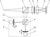
图1为本发明反射式差动共焦透镜中心厚度测量方法的示意图; Fig. 1 is the schematic diagram of reflective differential confocal lens central thickness measuring method of the present invention;
图2为本发明反射式差动共焦透镜中心厚度测量实施例的示意图; Fig. 2 is the schematic diagram of embodiment of reflective differential confocal lens central thickness measurement of the present invention;
图3为本发明由差动共焦测量系统探测得到的差动共焦响应曲线; Fig. 3 is the differential confocal response curve that the present invention detects by differential confocal measurement system;
其中:1-点光源、2-分光镜、3-准直透镜、4-环形光瞳、5-被测透镜、6-测量光束、7-平面反射镜、8-差动共焦测量系统、9-分光镜、10-焦前针孔、11-焦前光强传感器、12-焦后针孔、13-焦后光强传感器、14-焦前显微物镜、15-CCD探测器、16-焦后显微物镜、17-CCD探测器、18-点光源发生装置、19-光纤、20-激光器、21-主控计算机、22-图像采集卡、23-图像采集卡、24-机电控制装置、25-直线平移导轨、26-二维调整架。 Among them: 1-point light source, 2-beam splitter, 3-collimator lens, 4-annular pupil, 5-lens under test, 6-measurement beam, 7-plane mirror, 8-differential confocal measurement system, 9-beam splitter, 10-pinhole before focus, 11-light sensor before focus, 12-pinhole after focus, 13-light intensity sensor after focus, 14-microscopic objective lens before focus, 15-CCD detector, 16-display after focus Micro-objective lens, 17-CCD detector, 18-point light source generating device, 19-optical fiber, 20-laser, 21-main control computer, 22-image acquisition card, 23-image acquisition card, 24-electromechanical control device, 25- Linear translation guide rail, 26-two-dimensional adjustment frame. the
具体实施方式Detailed ways
下面结合附图和实施例对本发明作进一步说明。 The present invention will be further described below in conjunction with drawings and embodiments. the
本发明利用被测透镜自身出射的光束借助平面反射镜反射后形成测量光束,并结合差动共焦定焦技术对被测透镜前后表面的顶点进行高精度的定焦瞄准,进而测得被测透镜的中心厚度。同时,本发明还在测量光路中引入环形光瞳,遮挡近轴光线,形成空心的测量光锥,削减了像差对测量结果的影响。 In the present invention, the light beam emitted by the measured lens itself is reflected by a plane mirror to form a measuring light beam, and combined with the differential confocal fixed-focus technology, the vertices of the front and rear surfaces of the measured lens are targeted with high precision, and then the measured The center thickness of the lens. At the same time, the present invention also introduces an annular pupil into the measurement light path to block the paraxial light rays and form a hollow measurement light cone, which reduces the influence of aberrations on the measurement results. the
实施例1 Example 1
如附图1和附图2所示,反射式差动共焦透镜中心厚度测量方法,其测量步骤是: As shown in accompanying drawing 1 and accompanying drawing 2, the method for measuring the center thickness of reflective differential confocal lens, its measuring steps are:
(a)启动主控计算机21中的测量软件,输入相关参数,其主要包括被测透镜5后表面的曲率半径r2=100.7134mm、空气折射率n0=1、被测透镜5折射率n=1.5143和测量光束6的数值孔径角α0=5.8°。 (a) Start the measurement software in the
(b)打开激光器20,激光器20所发出的光经光纤19传输后形成点光源1。点光源1发出的光经分光镜2、准直透镜3形成平行光束; (b) Turn on the
(c)将平面反射镜7放置于二维调整架26上,通过二维调整架26调整平面反射镜7,使其表面与平行光束光轴相垂直; (c) Place the
(d)将被测透镜5放置于准直透镜3和平面反射镜6之间,调整被测透镜5,使其与准直透镜3共光轴。平行光照射在被测透镜5上,由被测透镜5会聚的光经平面反射镜7反射后形成测量光束6照射在被测透镜5的表面; (d) The measured
(e)主控计算机21中的测量软件通过机电控制装置24控制直线平移导轨25 轴向平移,进而带动平面反射镜7沿光轴方向移动。使测量光束6的聚焦焦点与被测透镜5的后表面接近。在该位置附近扫描平面反射镜7,测量软件通过图像采集卡22和图像采集卡23采集得到焦前光斑数据和焦后光斑数据并处理出如附图3所示的差动共焦响应曲线。通过差动共焦响应曲线的零点来确定测量光束6的聚焦焦点与被测透镜5的后表面相重合,记录此时平面反射镜的位置z1=0.0056mm; (e) The measurement software in the
(f)将平面反射镜7沿光轴向被测透镜5方向移动,使测量光束6的聚焦焦点与被测透镜5前表面接近,在该位置附近扫描平面反射镜7,测量软件再次通过图像采集卡22和图像采集卡23采集得到焦前光斑数据和焦后光斑数据并处理出如附图3所示的差动共焦响应曲线。通过差动共焦响应曲线的零点来确定测量光束6的聚焦焦点与被测透镜5前表面相重合,记录此时平面反射镜的位置z2=1.3438mm; (f) Move the
(g)根据已知参数:被测透镜5后表面的曲率半径r2100.7134mm、空气折射率n0=1、被测透镜5折射率n=1.5143、测量光束6的数值孔径角α0=5.8°,以及两次定位的平面反射镜移动量l=|z2-z1|=2.6764mm,将其带入以下公式: (g) According to known parameters: the radius of curvature r2 of the rear surface of the measured
可以得到被测透镜的中心厚度为d=8.0380mm。 It can be obtained that the central thickness of the tested lens is d=8.0380mm. the
如附图1所示,该反射式差动共焦透镜中心厚度测量方法中的差动共焦测量系统8包括分光镜9、焦前针孔10、焦前光强传感器11、焦后针孔12和焦后光强传感器13。由分光镜2反射回来的光进入差动共焦测量系统8,由分光镜9将光束分成两路,一路通过焦前针孔10后,照射在焦前光强传感器11上,另一路通过焦后针孔12后,照射在焦后光强传感器13上。在实际系统设计中,通常采用如附图2中所示的差动共焦测量系统8降低系统装调难度。该差动共焦测量系统8包括分光镜9、焦前显微物镜14、CCD探测器15、焦后显微物镜16和CCD探测器17。其中焦前显微物镜14的物平面位于焦前,在其像平面放置CCD探测器15,焦后显微物镜16的物平面位于焦后,在其像平面放置CCD探测器17。由分光镜2反射回来的光进入差动共焦测量系统8,由分光镜9将光线分成两路,一路通过焦前显微物镜14成像在CCD探测器15上,另一路通过焦后显微物镜16成像在CCD探测器17上。 As shown in accompanying drawing 1, the differential
实施例2 Example 2
与实施例1不同的是,在反射式差动共焦透镜中心厚度测量方法中加入环 形光瞳4遮挡近轴光线,继而完成对被测透镜5中心厚度的测量。由于加入环形光瞳4,则测量光束6形成空心的测量光锥,将有效削减像差对测量结果的影响。 The difference from Example 1 is that the
此实施例通过一系列的措施实现了对被测透镜中心厚度的非接触、高精度测量。具有对被测透镜无损伤、测量精度高、装调方便等优点。 This embodiment realizes the non-contact and high-precision measurement of the center thickness of the measured lens through a series of measures. It has the advantages of no damage to the measured lens, high measurement accuracy, and convenient installation and adjustment. the
以上结合附图对本发明的具体实施方式作了说明,但这些说明不能被理解为限制了本发明的范围,本发明的保护范围由随附的权利要求书限定,任何在本发明权利要求基础上的改动都是本发明的保护范围。 The specific embodiment of the present invention has been described above in conjunction with the accompanying drawings, but these descriptions can not be interpreted as limiting the scope of the present invention, the protection scope of the present invention is defined by the appended claims, any claims on the basis of the present invention All modifications are within the protection scope of the present invention. the
Claims (3)
Priority Applications (1)
| Application Number | Priority Date | Filing Date | Title |
|---|---|---|---|
| CN201210190779.9ACN102679894B (en) | 2012-06-11 | 2012-06-11 | Method for measuring central thickness of reflecting type differential confocal lens |
Applications Claiming Priority (1)
| Application Number | Priority Date | Filing Date | Title |
|---|---|---|---|
| CN201210190779.9ACN102679894B (en) | 2012-06-11 | 2012-06-11 | Method for measuring central thickness of reflecting type differential confocal lens |
Publications (2)
| Publication Number | Publication Date |
|---|---|
| CN102679894A CN102679894A (en) | 2012-09-19 |
| CN102679894Btrue CN102679894B (en) | 2014-07-09 |
Family
ID=46812185
Family Applications (1)
| Application Number | Title | Priority Date | Filing Date |
|---|---|---|---|
| CN201210190779.9AExpired - Fee RelatedCN102679894B (en) | 2012-06-11 | 2012-06-11 | Method for measuring central thickness of reflecting type differential confocal lens |
Country Status (1)
| Country | Link |
|---|---|
| CN (1) | CN102679894B (en) |
Cited By (1)
| Publication number | Priority date | Publication date | Assignee | Title |
|---|---|---|---|---|
| CN109211130A (en)* | 2018-09-18 | 2019-01-15 | 昆明北方红外技术股份有限公司 | The measuring device and method of lens center thickness and lens separation |
Families Citing this family (11)
| Publication number | Priority date | Publication date | Assignee | Title |
|---|---|---|---|---|
| CN103868464A (en)* | 2014-03-27 | 2014-06-18 | 西安交通大学 | Sensor for active leveling detection of nanoimprint lithography working tables |
| CN104154868A (en)* | 2014-08-06 | 2014-11-19 | 复旦大学 | A non-contact lens center thickness measurement device based on bifocal mirror |
| CN104197848B (en)* | 2014-09-18 | 2017-02-15 | 海宁科海光电科技有限公司 | Double-frequency differential thickness measurement method and equipment |
| CN107462405B (en)* | 2017-09-27 | 2019-03-19 | 北京理工大学 | Broadband differential confocal Infrared Lens element refractive index measurement method and device |
| JP7062518B2 (en)* | 2018-05-25 | 2022-05-06 | 株式会社キーエンス | Confocal displacement meter |
| CN109186477B (en)* | 2018-11-13 | 2020-05-12 | 北京理工大学 | Method and device for measuring central thickness of rear-mounted pupil laser differential confocal lens |
| CN110879042B (en)* | 2019-11-28 | 2020-11-20 | 中国科学院长春光学精密机械与物理研究所 | Optical path and method for non-contact measurement of lens group using LED light source |
| CN112666172B (en)* | 2020-12-01 | 2022-02-11 | 北京理工大学 | Differential confocal fixed surface interference target shot outer surface defect detection method and device |
| CN112630232B (en)* | 2020-12-01 | 2021-12-03 | 北京理工大学 | Method and device for detecting defects of inner surface and outer surface of differential confocal fixed-surface interference target pill |
| CN112683918B (en)* | 2020-12-01 | 2022-02-11 | 北京理工大学 | Differential confocal fixed surface interference target shot inner surface defect detection method and device |
| CN113048895B (en)* | 2021-03-04 | 2022-08-16 | 上海精测半导体技术有限公司 | Apparatus and method for detecting change of reflected light, and film thickness measuring apparatus |
Citations (5)
| Publication number | Priority date | Publication date | Assignee | Title |
|---|---|---|---|---|
| CN101403650A (en)* | 2008-11-21 | 2009-04-08 | 北京理工大学 | Differential confocal combination ultra-long focal length measuring method and apparatus |
| DE102008017091A1 (en)* | 2008-04-02 | 2009-10-08 | Bundesrepublik Deutschland, vertr.d.d. Bundesministerium für Wirtschaft und Technologie, d.vertr.d.d. Präsidenten der Physikalisch-Technischen Bundesanstalt | Microscope i.e. differential confocal microscope, for use in topography measuring device, has light measuring device measuring light intensity at position, and including offset for light sensor with respect to optical axis |
| CN101769821A (en)* | 2010-02-04 | 2010-07-07 | 北京理工大学 | Lens refractive index and thickness measuring method and device based on differential confocal technology |
| CN101793500A (en)* | 2010-01-13 | 2010-08-04 | 北京理工大学 | Method and device for measuring central thickness of differential confocal lens |
| CN102147240A (en)* | 2010-12-24 | 2011-08-10 | 北京理工大学 | Method and device for measuring multiple element parameters in differential con-focus interference manner |
Family Cites Families (1)
| Publication number | Priority date | Publication date | Assignee | Title |
|---|---|---|---|---|
| US5785651A (en)* | 1995-06-07 | 1998-07-28 | Keravision, Inc. | Distance measuring confocal microscope |
- 2012
- 2012-06-11CNCN201210190779.9Apatent/CN102679894B/ennot_activeExpired - Fee Related
Patent Citations (5)
| Publication number | Priority date | Publication date | Assignee | Title |
|---|---|---|---|---|
| DE102008017091A1 (en)* | 2008-04-02 | 2009-10-08 | Bundesrepublik Deutschland, vertr.d.d. Bundesministerium für Wirtschaft und Technologie, d.vertr.d.d. Präsidenten der Physikalisch-Technischen Bundesanstalt | Microscope i.e. differential confocal microscope, for use in topography measuring device, has light measuring device measuring light intensity at position, and including offset for light sensor with respect to optical axis |
| CN101403650A (en)* | 2008-11-21 | 2009-04-08 | 北京理工大学 | Differential confocal combination ultra-long focal length measuring method and apparatus |
| CN101793500A (en)* | 2010-01-13 | 2010-08-04 | 北京理工大学 | Method and device for measuring central thickness of differential confocal lens |
| CN101769821A (en)* | 2010-02-04 | 2010-07-07 | 北京理工大学 | Lens refractive index and thickness measuring method and device based on differential confocal technology |
| CN102147240A (en)* | 2010-12-24 | 2011-08-10 | 北京理工大学 | Method and device for measuring multiple element parameters in differential con-focus interference manner |
Non-Patent Citations (2)
| Title |
|---|
| 史立波等.激光差动共焦透镜中心厚度测量系统的研制.《仪器仪表学报》.2012,第33卷(第3期),全文. |
| 激光差动共焦透镜中心厚度测量系统的研制;史立波等;《仪器仪表学报》;20120331;第33卷(第3期);全文* |
Cited By (2)
| Publication number | Priority date | Publication date | Assignee | Title |
|---|---|---|---|---|
| CN109211130A (en)* | 2018-09-18 | 2019-01-15 | 昆明北方红外技术股份有限公司 | The measuring device and method of lens center thickness and lens separation |
| CN109211130B (en)* | 2018-09-18 | 2020-03-31 | 昆明北方红外技术股份有限公司 | Device and method for measuring lens center thickness and lens spacing |
Also Published As
| Publication number | Publication date |
|---|---|
| CN102679894A (en) | 2012-09-19 |
Similar Documents
| Publication | Publication Date | Title |
|---|---|---|
| CN102679894B (en) | Method for measuring central thickness of reflecting type differential confocal lens | |
| CN102679895B (en) | Method for measuring center thickness of reflective confocal lens | |
| CN101793500B (en) | Method and device for measuring center thickness of differential confocal lens | |
| CN109253989B (en) | A kind of laser differential confocal tomography fixed focus method and device | |
| CN102147240B (en) | Method and device for measuring multiple element parameters in differential con-focus interference manner | |
| CN102175426B (en) | Confocal Interferometric Fixed Focus and Curvature Radius Measurement Method | |
| CN101788271A (en) | Method and device for measuring thickness of the center of confocal lens | |
| CN102589851B (en) | Method for Measuring Focal Length of Reflective Confocal Lens | |
| CN102589852B (en) | Measuring method of focal length of self-collimating confocal lens | |
| CN105758336B (en) | Reflective laser differential confocal curvature radius measurement method and device | |
| CN102589854B (en) | Method for Measuring Focal Length of Reflective Differential Confocal Lens | |
| CN103123251B (en) | Differential confocal internal focusing method lens axis and method for measuring thickness | |
| CN101526341A (en) | Differential confocal curvature radius measurement method and device | |
| CN102589853B (en) | Measuring method of focal length of autocollimation differential confocal lens | |
| CN104315985B (en) | Interferometric method for measuring central thickness of lens | |
| CN102645322B (en) | Spherical aberration measurement method of differential confocal system | |
| CN103471524B (en) | Confocal paraboloids vertex curvature radius measuring method | |
| CN104833486A (en) | Multi-reflection laser differential confocal long focal length measuring method and multi-reflection laser differential confocal long focal length measuring device | |
| CN109186477B (en) | Method and device for measuring central thickness of rear-mounted pupil laser differential confocal lens | |
| CN101762240A (en) | Method and device for measuring axial gaps of differential confocal lens set | |
| CN103105283B (en) | Focal length measuring device of single-spectrum large-caliber long-focus lens | |
| CN103471525B (en) | Differential confocal parabola vertex curvature radius measurement method | |
| CN109990982B (en) | Reflection type transverse subtraction differential confocal focal length measuring method | |
| CN109990732A (en) | Measurement method of lateral subtraction differential confocal radius of curvature | |
| CN109974603B (en) | Method for measuring center thickness of bilateral dislocation differential confocal lens |
Legal Events
| Date | Code | Title | Description |
|---|---|---|---|
| C06 | Publication | ||
| PB01 | Publication | ||
| C10 | Entry into substantive examination | ||
| SE01 | Entry into force of request for substantive examination | ||
| C14 | Grant of patent or utility model | ||
| GR01 | Patent grant | ||
| CF01 | Termination of patent right due to non-payment of annual fee | Granted publication date:20140709 | |
| CF01 | Termination of patent right due to non-payment of annual fee |