CN102670294A - Bone anchoring device - Google Patents
Bone anchoring deviceDownload PDFInfo
- Publication number
- CN102670294A CN102670294ACN2012101360753ACN201210136075ACN102670294ACN 102670294 ACN102670294 ACN 102670294ACN 2012101360753 ACN2012101360753 ACN 2012101360753ACN 201210136075 ACN201210136075 ACN 201210136075ACN 102670294 ACN102670294 ACN 102670294A
- Authority
- CN
- China
- Prior art keywords
- locking
- acceptance division
- bone anchoring
- head
- locking device
- Prior art date
- Legal status (The legal status is an assumption and is not a legal conclusion. Google has not performed a legal analysis and makes no representation as to the accuracy of the status listed.)
- Granted
Links
- 210000000988bone and boneAnatomy0.000titleclaimsabstractdescription71
- 238000004873anchoringMethods0.000titleclaimsabstractdescription60
- 230000004048modificationEffects0.000description5
- 238000012986modificationMethods0.000description5
- 239000007943implantSubstances0.000description4
- 230000008901benefitEffects0.000description3
- 238000000354decomposition reactionMethods0.000description3
- 238000010586diagramMethods0.000description3
- 230000004323axial lengthEffects0.000description2
- 230000008878couplingEffects0.000description2
- 238000010168coupling processMethods0.000description2
- 238000005859coupling reactionMethods0.000description2
- 230000015572biosynthetic processEffects0.000description1
- 230000008859changeEffects0.000description1
- 230000001419dependent effectEffects0.000description1
- 238000005516engineering processMethods0.000description1
- 230000002349favourable effectEffects0.000description1
- 230000006872improvementEffects0.000description1
- 238000001356surgical procedureMethods0.000description1
- LENZDBCJOHFCAS-UHFFFAOYSA-NtrisChemical compoundOCC(N)(CO)COLENZDBCJOHFCAS-UHFFFAOYSA-N0.000description1
Images


Classifications
- A—HUMAN NECESSITIES
- A61—MEDICAL OR VETERINARY SCIENCE; HYGIENE
- A61B—DIAGNOSIS; SURGERY; IDENTIFICATION
- A61B17/00—Surgical instruments, devices or methods
- A61B17/56—Surgical instruments or methods for treatment of bones or joints; Devices specially adapted therefor
- A61B17/58—Surgical instruments or methods for treatment of bones or joints; Devices specially adapted therefor for osteosynthesis, e.g. bone plates, screws or setting implements
- A61B17/68—Internal fixation devices, including fasteners and spinal fixators, even if a part thereof projects from the skin
- A61B17/70—Spinal positioners or stabilisers, e.g. stabilisers comprising fluid filler in an implant
- A61B17/7001—Screws or hooks combined with longitudinal elements which do not contact vertebrae
- A61B17/7032—Screws or hooks with U-shaped head or back through which longitudinal rods pass
- A—HUMAN NECESSITIES
- A61—MEDICAL OR VETERINARY SCIENCE; HYGIENE
- A61B—DIAGNOSIS; SURGERY; IDENTIFICATION
- A61B17/00—Surgical instruments, devices or methods
- A61B17/56—Surgical instruments or methods for treatment of bones or joints; Devices specially adapted therefor
- A61B17/58—Surgical instruments or methods for treatment of bones or joints; Devices specially adapted therefor for osteosynthesis, e.g. bone plates, screws or setting implements
- A61B17/68—Internal fixation devices, including fasteners and spinal fixators, even if a part thereof projects from the skin
- A61B17/70—Spinal positioners or stabilisers, e.g. stabilisers comprising fluid filler in an implant
- A61B17/7001—Screws or hooks combined with longitudinal elements which do not contact vertebrae
- A61B17/7035—Screws or hooks, wherein a rod-clamping part and a bone-anchoring part can pivot relative to each other
- A61B17/7037—Screws or hooks, wherein a rod-clamping part and a bone-anchoring part can pivot relative to each other wherein pivoting is blocked when the rod is clamped
- A—HUMAN NECESSITIES
- A61—MEDICAL OR VETERINARY SCIENCE; HYGIENE
- A61B—DIAGNOSIS; SURGERY; IDENTIFICATION
- A61B17/00—Surgical instruments, devices or methods
- A61B17/56—Surgical instruments or methods for treatment of bones or joints; Devices specially adapted therefor
- A61B17/58—Surgical instruments or methods for treatment of bones or joints; Devices specially adapted therefor for osteosynthesis, e.g. bone plates, screws or setting implements
- A61B17/68—Internal fixation devices, including fasteners and spinal fixators, even if a part thereof projects from the skin
- A61B17/74—Devices for the head or neck or trochanter of the femur
Landscapes
- Health & Medical Sciences (AREA)
- Orthopedic Medicine & Surgery (AREA)
- Life Sciences & Earth Sciences (AREA)
- Surgery (AREA)
- Neurology (AREA)
- Heart & Thoracic Surgery (AREA)
- Engineering & Computer Science (AREA)
- Biomedical Technology (AREA)
- Nuclear Medicine, Radiotherapy & Molecular Imaging (AREA)
- Medical Informatics (AREA)
- Molecular Biology (AREA)
- Animal Behavior & Ethology (AREA)
- General Health & Medical Sciences (AREA)
- Public Health (AREA)
- Veterinary Medicine (AREA)
- Surgical Instruments (AREA)
Abstract
Description
The application is that December in 2007 was submitted on the 19th, application number is 200710160328.X, name is called the dividing an application of application of " bone anchoring device ".
Technical field
The present invention relates to bone anchoring device, it comprises and will be anchored at the body rod in bone or the vertebra and be connected to body rod to receive the acceptance division of a bar.Said bar is locked by locking device, and this locking device has the connected structure that is used for a tool engagement, and connected structure is located at the excircle place of locking device.Connected structure is projected into the acceptance division top, but outstanding above acceptance division on side direction.Especially, the present invention relates to the multiaxis bone screw, wherein the head of screw and a bar can be fixed independently, and this screw has the size that reduces.
Background technology
US 6 224 598 B1 disclose a kind of be suitable for being used in the bar member is fixed to the thread plug closure member in the bone screw implant; Said closure member comprises: the connector with threaded cylindrical outer surface; In the use, said connector is received between a pair of arm of medical implant; Pass completely through the center coaxial aperture of said connector, said centre bore has threaded inner surface, and it is configured as the reception dog screw.Connector closure member and dog screw can be installed independently, and fastening dog screw is so that provide catching and locking of bar jointly, thereby anti-stopping bar is with respect to the bone screw translational motion with rotatablely move.
US 2003/0100896A1 discloses a kind of bone anchoring device, and it has body rod and is connected with it to be used to be connected to the acceptance division of a bar.This acceptance division has recess, and this recess has the U-shaped cross-section of two opening supporting legs of formation to be used to receive bar.Female thread is located on the opening supporting leg.Be provided with locked component, it comprises: have externally threaded nut member and dog screw with the screw-internal thread fit of supporting leg.Nut member at one end has the slit that is used for the screw tool engagement.Body rod has spherical head, and this head remains in the acceptance division pivotly, and is provided with a pressure elements, and this pressure elements is exerted pressure on head when nut member is fastened.Through fastening dog screw, bar is fixed in the acceptance division.Therefore, bar and head can be fixed independently of one another.The external screw thread of the cooperation of female thread and nut member is designed to flat thread.This implant has Compact Design, and reason is to prevent that the open outer shroud of supporting leg or nut are dispensable.
US 6 063 090 discloses a kind of bone anchoring device, and this bone anchoring device has: two parts locked components; Tensioning screw, it is via the fixing spherical head and do not have pressure ram of a plug-in unit; And the tensioner of fixed bar.
US 2006/0036244A1 also discloses a kind of bone anchoring device that has two parts locking caps, and said locking cap is used for fixing head and bar independently.Tensioning screw has coaxial recess, and this recess has the structure that is used for tool engagement.
The external diameter of locking device is confirmed by required tensioning moment of torsion and thread forms down in every respect.Conversely, the overall dimension of the top part of bone anchoring device is confirmed by the size of locking device.Using for some, crucially is that the distance between a bone anchoring device and the adjacent bone anchor fixing apparatus is as far as possible little, for example for rectification baby's skoliosis or for the application in the cervical region of spinal column.
Summary of the invention
The purpose of this invention is to provide a kind of bone anchoring device that has locking device, its reliability is identical with known devices, but the size of the top part on the rod axis direction is obviously littler.This purpose realizes through the bone anchoring device according to claim 1.Other embodiment of bone anchoring device provides in the dependent claims.
Be used in according to the locking device in the bone anchoring device of the present invention and have the structure that is used for tool engagement, it is located on the outer surface of upper member of locking device.Therefore, can reduce along the size of the bone anchoring device of rod axis direction.Locking device can be better near instrument, and this helps perioperative processing.The bone anchoring device near ability with this size that reduces and improvement is particularly suitable for being applied to paediatric surgery or is applied to cervical vertebra or other field, the implant that wherein limited obtained space requirement is compact.Locking device is designed to make that retainer provides safety, prevents in use to disintegrate.
Can also utilize according to pressure elements of the present invention and the upgrading of two parts locking devices and have the existing multiaxis bone screw of single part locking device.In addition, bone anchoring device has following advantage: it can be selected locking device in two ways and be used.If select the single part locking device, can simultaneously head be locked in multiaxis position and fixed bar.If select two parts locking devices, discretely locking head and fixed bar.
In addition, this bone anchoring device compact dimensions, reason is that it needn't use outer nut or ring to prevent that the supporting leg of acceptance division from opening.
In conjunction with accompanying drawing, other features and advantages of the present invention will become obvious from the description of embodiment.
Description of drawings
Fig. 1 has shown the decomposition diagram according to the bone anchoring device of the first embodiment of the present invention.
Fig. 2 has shown the perspective view of the bone anchoring device under the assembled state.
Fig. 3 has shown the sectional view of the bone anchoring device under the assembled state, and this cross section is along the planar interception perpendicular to rod axis.
Fig. 4 has shown the cutaway view according to the locking device of first embodiment.
Fig. 5 has shown the side view of the locking device of Fig. 4.
Fig. 6 has shown the vertical view according to the locking device of Fig. 4.
Fig. 7 has shown the decomposition diagram according to the bone anchoring device of second embodiment.
Fig. 8 shown under the assembled state, according to the sectional view of the bone anchoring device of second embodiment, this cross section is along the planar interception perpendicular to rod axis.
Fig. 9 a has shown the amplifier section of Fig. 8; Fig. 9 b has shown the part of describing like Fig. 9 a, and locking member has the connected structure of minimum outer diameter.
Figure 10 has shown the decomposition diagram according to the bone anchoring device of the 3rd embodiment.
Figure 11 has schematically shown the locking device and the pressure apparatus according to first embodiment of the existing multiaxis bone screw that is used to upgrade.
Figure 12 has shown the modular system of the bone anchoring device that comprises first, second and the bone anchoring device of the 3rd embodiment.
The specific embodiment
As can find out from Fig. 1-3 that particularly comprisescrew element 1 according to the bone anchoring device of first embodiment, it has thebody rod 2 andhead 3 of band bone thread (not shown).In this embodiment,head 3 has the segment shape.On itself and body rod opposite surfaces,head 3 comprises the recess 3a that is used for toolengagement.Screw element 1 is received in the acceptance division 4, and this acceptance division hasfirst end 5 andsecond end 6, and is the general cylindrical shape structure.Above-mentioned two ends are perpendicular to longitudinal axes L.Be provided with porosely 7 coaxially with longitudinal axes L, it extends to from second end, 6 preset distances from first end 5.Be provided with opening 8 atsecond end 6, its diameter is less than the diameter in hole 7.Coaxial aperture 7 is towards opening 8 convergents.In the embodiment shown, it is with the form convergent of spherical part 9.Butpart 9 can have any other shape, and is for example conical.
Acceptance division 4 also comprisesU-shaped recess 10, and its direction that starts fromfirst end 5 and edgesecond end 6 extends to from second end, 6 one distances.By means of the U-shaped recess, form two free supportinglegs Female thread 13 is located on the inner surface of supportingleg 11,12.In the embodiment shown, female thread is the female thread with horizontal upper part and lower thread tooth side.
In addition,pressure elements 14 is set, it is roughly cylindrical configuration, and the size of external diameter is set authorizedpressure element 14 for and introduced in thehole 7 of acceptance divisions and motion in axial direction.On the downside ofsecond end 6,pressure elements 14 comprises therecess 15 that cooperates withhead 3 at it.Recess 15 can be spherical, with the profile of the spherical part of coupling head 3.At its opposite side,pressure elements 14 has U-shapedrecess 16, has formed two free supportinglegs bar 20 of D can be inserted in therecess 16 and by transverse guidance to wherein.The degree of depth ofU-shaped recess 16 is greater than the diameter D ofbar 20, makes when bar is inserted into supportingleg recess 21 at the inboard of supportingleg upper end.Hole 19 be located in the pressure elements so that the head ofscrew element 3 near instrument.
As can beappreciated from fig. 3;Pressure elements 14 and acceptance division 4 can be respectively have distortion (crimp) hole in both sides relatively, so as withpressure elements 14 loose grounds remain in the acceptance division, the U-shaped recess 16 ofpressure elements 14 and the U-shaped recess 10 aligned positions of acceptance division.
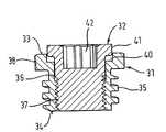
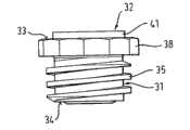
Bone anchoring device also comprises locking device 30.As especially shown in Fig. 1-6,locking device 30 comprisesfirst locking component 31 andsecond locking component 32.
The part thatfirst locking component 31 hasfirst end 33 andsecond end 34 and has the general cylindrical shape shape hasexternal screw thread 35 on the outer surface of this part.As especially shown in the Figure 4 and 5,external screw thread 35 is flat threads of thefemale thread 13 of coupling acceptance division 4.First locking component 31 also comprises theaxial hole 36 that extends through whole first locking component.Axial hole 36 is provided withfemale thread 37 on its at least a portion, this part is roughly corresponding to the externally threaded surface portion of being with of first locking component.In this embodiment,female thread 37 is depicted as and forms metric thread.The axial length of the threaded outer surface part that hasexternal screw thread 35 offirst locking component 31 makesexternal screw thread 35 cooperate with thefemale thread 13 of supportingleg
The axial length ofsecond locking component 32 is like this, makes to be inserted in first locking component and locking device when being screwed between the supporting leg of acceptance division whensecond locking component 32, and second locking component is pressed onto on thebar 20, butcontact pressure element 14 not.As can beappreciated from fig. 3, between the downside of the bottom of therecess 20 of pressure elements and second locking component, there isgap 43.
In the operation, at first, at least two common pre-assembled bone anchoring devices are screwed in the bone, each bone anchoring device includesscrew element 1, acceptance division 4 andpressure elements 14.
After this,bar 20 is inserted in the U-shapedrecess 10 of acceptance division 4.Then, will comprise can pre-assembledfirst locking component 31 and thelocking device 30 ofsecond locking component 32 is screwed into the supportingleg 11 of acceptance division 4, between 12.Then through the instrument (not shown) being applied on connectedstructure 38 is pressed in pressure elements up tofirst locking component 31 the free supporting leg and fastening first locking component 31.Through fasteningfirst locking component 31,pressure elements 14 is exerted pressure on thehead 3 ofscrew element 1,head 3 is locked in its angular position in the acceptance division 4.The retainer that connectedstructure 38 provides is restricted to occurrence with the power that applies.
When head was locked,bar 20 still can slide in acceptance division.Move downward and be pressed onto on the bar through fastening second locking component, 32, the second locking components, bar is fixed on its position.The power that is applied on the bar can limit through using the retainer that is provided against theannular shoulder 41 of the bottom ofrecess 40 well.
Through on its size, doing lessly in that connectedstructure 38, the first locking components are set on the excircle of first locking component, particularly wherein the diameter of threaded outer surface part is less.Iffirst locking component 31 can be done to such an extent that external diameter is less, then acceptance division also can be done to such an extent that external diameter is less.As a result, the distance on the direction of bar can be less between two boneanchoring devices.Shoulder 41 helps the processing of second locking component.
Second embodiment of bone anchoring device is shown in Fig. 7-9a and the 9b.The parts identical with first embodiment are represented with identical Reference numeral, and are no longer repeated its description.Bone anchoring device according to second embodiment comprises singlepart locking device 50.
Shown in Fig. 7-9b, the single part locking device is an inner bolt, and it can be screwed in the supportingleg 11 of acceptance division 4, between 12.In this embodiment, thescrew thread 55 of screw for be located at supporting leg on the flat thread that cooperates of flat thread.Inner bolt hasprojection 51 at it on a side ofpressure elements 14, the size of its diameter is just in time like this, and promptlyprojection 51 can be pressed on thebar 20 but not have the contact pressure element.The length of the length of singlepart locking device 50 andcylindrical projections 51 is like this; Make as shown in Figure 8 under tight condition,cylindrical projections 51 contact levers and at the supportingleg 17 of thelower surface 53 of single part locking device andpressure elements 14, havegap 52 between 18.Singlepart locking device 50 comprises connectedstructure 54 on a side relative withprojection 51, it has polygonal shape to be used for joining tool.Connectedstructure 54 is similar with the connectedstructure 38 offirst locking component 31 of the twoparts locking devices 30 of first embodiment.Shown in Fig. 9 a, D outer diameter is less than the D outer diameter R of the acceptance division in the supporting leg zone 4.Shown in Fig. 9 b, in the littler modification of locking member, D outer diameter ' only be a bit larger tham the inside diameter D T of female thread.
Connected structure is projected into acceptance division 4 tops.Therefore, help the fastening of intra-operative locking member and instrument, reason is that connected structure is easily near instrument.
The use of this bone anchoring device is identical with first embodiment, replaces thelocking device 30 of first embodiment except using single part locking device 50.In this case, singlepart locking device 50 is pressed on the bar, and bar is pressed in again on thepressure elements 14, so thathead 3 is fixed in the acceptance division 4.Therefore, bar and head are fixed simultaneously.
Figure 10 has shown the 3rd embodiment of bone anchoring device.The difference of itself and second embodiment mainly is the shape of pressure elements.All other parts are all identical.The difference of thepressure elements 14 of thepressure elements 140 and first and second embodiment is that it has short supporting leg 141,142, and when bar was inserted into, these supporting legs were not projected into the top of bar.All further features are all identical withpressure elements 14.
In another modification,pressure elements 140 is not used in the recess that receives bar, does not also have supporting leg.It can form pressure disc.In another modification, singlepart locking device 50 is not used in theprojection 51 that is pressed on the bar.
Figure 11 schematically shown according to locking device of the bone anchoring device offirst embodiment 30 andpressure elements 14, and it is used to upgrade and has an existing multiaxis bone screw of single part locking member.Knownmultiaxis bone screw 200 has the singlepart locking member 250 andpressure disc 214 of dog screw form.Compare with the bone anchoring device with singlepart locking member 250, with regard to the external diameter of acceptance division, the size of known bone anchors fixing apparatus that has two parts locking device (not shown)s is bigger.But, can changedog screws 250 and thepressure disc 214 existingbone anchoring device 200 of upgrading through utilizing according to thelocking device 30 of first embodiment and pressure elements 14.Therefore, minimized in size and have the bone anchoring device of the advantage of fixed bar and head independently is provided.
Figure 12 has shown the modular system of the bone anchoring device that comprises first, second and the bone anchoring device of the 3rd embodiment.Ifworking pressure element 14 then can use single part locking device and two parts locking devices with exchanging.Alternatively, the single part locking device can use withpressure elements
The surgeon can select singlepart locking device 50 or twoparts locking devices 30 to use with identical bone anchoring device is collaborative.Use for some, the single part locking device that is used for while locking head and bar is favourable, if particularly must promptly fix.For some application, advantageously fixing head and bar discretely.Because the surgeon can use identical bone anchoring device and can freely select required locking device, therefore needn't prepare different received portion and different pressure elements for different bone anchoring devices.
Can carry out modification to these embodiment.Replace flat thread, can use other thread forms.In addition,head 3 against thepart 10 of acceptance division 4 needn't be sphere, but can have other shape, as long ashead 3 is kept by the edge of opening 8, just as ball and engage.In another modification, acceptance division is designed to allow from second end, introduces head from the bottom of acceptance division.
Claims (13)
1. bone anchoring device comprises:
Anchoring element (1) comprises the body rod (2) that will be anchored in bone or the vertebra,
Acceptance division (4), it is connected to body rod, and said acceptance division comprises: first end (5) opposite with body rod and in the face of second end (6) of body rod; Pass the longitudinal axis (L) at two ends; With the co-axial hole of longitudinal axis (7), it extends through at least a portion of acceptance division from first end; And the cardinal principle U-shaped recess (10) that is used to receive rod member (20); This recess forms two the free supporting legs (11,12) that extend to the direction of first end, and said supporting leg is provided with female thread (13),
Locking device (30; 50), be used for rod member is fixed on acceptance division, said locking device comprises:
The external screw thread (35 that cooperates with female thread (13); 55), and
Connected structure (38; 54); It is located on the circumference of at least a portion of outer surface of first end (5) top that is projected into acceptance division; This structure can engage with the mode of an instrument with form fit, and the maximum outside diameter of wherein said locking device in the zone of said connected structure (38) is greater than the internal diameter of the female thread (13) of acceptance division;
Wherein, said connected structure (38; 54) said external diameter is less than the external diameter of said acceptance division in the zone of said supporting leg (11,12).
2. according to the bone anchoring device of claim 1, it is characterized in that: said anchoring element comprises head (3), and said acceptance division (4) comprises contiguous said second end, is used for receiving pivotly the zone (9) of said head.
3. according to the bone anchoring device of claim 2, also comprise pressure elements (14), it is arranged in the acceptance division (4), between head (3) and the locking device (30), be used on said head, exerting pressure, so that head is locked in the acceptance division.
4. according to the bone anchoring device of claim 3, it is characterized in that: said pressure elements (14) has the cardinal principle U-shaped recess (16) of at least a portion that is used to receive rod member (20), and this concave depth is greater than the diameter of rod member.
5. according to each bone anchoring device among the claim 1-4, it is characterized in that: said locking device (30) is two parts locking devices, comprising:
First locking component (31), this first locking component has: first end (33) and on its at least a portion, be provided with second end (34) of external screw thread (35), this external screw thread cooperates with female thread (13) on being located at said supporting leg; Coaxial aperture (36), it passes completely through first locking component; And being located at the female thread (37) at least a portion of said coaxial aperture, wherein said first locking component is provided with said connected structure (38), and
Second locking component (32), second locking component has outer surface, and this outer surface is having on its at least a portion and the external screw thread that is located at the screw-internal thread fit on the said coaxial aperture (36) of first locking component (31).
6. according to the bone anchoring device of claim 5, it is characterized in that: said first locking component (31) is designed to locking head under the situation of fixed beam not, and said second locking component (32) is designed to fixing said rod member.
7. according to each bone anchoring device among the claim 1-6, it is characterized in that: locking device (50) comprises the single part locking member, and it has said connected structure (38; 54).
8. according to the bone anchoring device of claim 7, it is characterized in that: said single part locking member has projection (51) at it on a side of rod member (20).
9. according to the bone anchoring device of claim 7 or 8; It is characterized in that: a pressure elements (14) is arranged in the acceptance division (4), between head (3) and the locking device (50); Be used on said head, exerting pressure, and the size of locking device (50) is set under assembled state and between locking device (50) and pressure elements (14), gap (52) is provided.
10. according to each bone anchoring device among the claim 1-9, it is characterized in that: said connected structure (38; 54) outline is polygon or star.
11., it is characterized in that: said connected structure (38 according to each bone anchoring device among the claim 1-10; 54) external diameter is greater than locking device (30; 50) external screw thread (35; 55) external diameter.
12. a modular system comprises:
Anchoring element (1) comprises the body rod (2) that will be anchored in bone or the vertebra,
Acceptance division (4), it is connected to body rod, and said acceptance division comprises: first end (5) opposite with body rod and in the face of second end (6) of body rod; Pass the longitudinal axis (L) at above-mentioned two ends; With the co-axial hole of longitudinal axis (7), it extends through at least a portion of acceptance division from first end; And the cardinal principle U-shaped recess (10) that is used to receive rod member (20); This recess forms two the free supporting legs (11,12) that extend to the direction of first end, and said supporting leg is provided with female thread (13),
Pressure elements (14); It is arranged in the acceptance division (4), between head (3) and the locking device (30); Be used on said head, exerting pressure, so that head is locked in the acceptance division, wherein said pressure elements (14) has the cardinal principle U-shaped recess (16) of at least a portion that is used to receive rod member (20); This concave depth is greater than the diameter of rod member
According to two parts locking devices (30) of claim 5 or 6 and according to each single part locking device (50) among the claim 7-9.
13. the modular system according to claim 12 is characterized in that: two parts locking devices (30) and single part locking device (50) can use with exchanging.
Applications Claiming Priority (4)
| Application Number | Priority Date | Filing Date | Title |
|---|---|---|---|
| US87667006P | 2006-12-22 | 2006-12-22 | |
| EP06026705AEP1935358B1 (en) | 2006-12-22 | 2006-12-22 | Bone anchoring device |
| EP06026705.1 | 2006-12-22 | ||
| US60/876,670 | 2006-12-22 |
Related Parent Applications (1)
| Application Number | Title | Priority Date | Filing Date |
|---|---|---|---|
| CN200710160328XADivisionCN101264030B (en) | 2006-12-22 | 2007-12-19 | Bone anchoring device |
Publications (2)
| Publication Number | Publication Date |
|---|---|
| CN102670294Atrue CN102670294A (en) | 2012-09-19 |
| CN102670294B CN102670294B (en) | 2014-10-15 |
Family
ID=38024289
Family Applications (2)
| Application Number | Title | Priority Date | Filing Date |
|---|---|---|---|
| CN201210136075.3AExpired - Fee RelatedCN102670294B (en) | 2006-12-22 | 2007-12-19 | Bone anchoring device |
| CN200710160328XAExpired - Fee RelatedCN101264030B (en) | 2006-12-22 | 2007-12-19 | Bone anchoring device |
Family Applications After (1)
| Application Number | Title | Priority Date | Filing Date |
|---|---|---|---|
| CN200710160328XAExpired - Fee RelatedCN101264030B (en) | 2006-12-22 | 2007-12-19 | Bone anchoring device |
Country Status (7)
| Country | Link |
|---|---|
| US (2) | US8343191B2 (en) |
| EP (2) | EP2322107B1 (en) |
| JP (1) | JP5479678B2 (en) |
| KR (1) | KR101530681B1 (en) |
| CN (2) | CN102670294B (en) |
| ES (2) | ES2395948T3 (en) |
| TW (2) | TWI444167B (en) |
Cited By (2)
| Publication number | Priority date | Publication date | Assignee | Title |
|---|---|---|---|---|
| CN104434283A (en)* | 2013-09-19 | 2015-03-25 | 比德尔曼技术有限责任两合公司 | Coupling assembly for coupling rod to bone anchoring element, polyaxial bone anchoring device and modular stabilization device |
| WO2017071403A1 (en)* | 2015-10-30 | 2017-05-04 | 北京市富乐科技开发有限公司 | Minimally invasive double screw-plug bolt |
Families Citing this family (79)
| Publication number | Priority date | Publication date | Assignee | Title |
|---|---|---|---|---|
| US7833250B2 (en) | 2004-11-10 | 2010-11-16 | Jackson Roger P | Polyaxial bone screw with helically wound capture connection |
| US8377100B2 (en) | 2000-12-08 | 2013-02-19 | Roger P. Jackson | Closure for open-headed medical implant |
| US11224464B2 (en) | 2002-05-09 | 2022-01-18 | Roger P. Jackson | Threaded closure with inwardly-facing tool engaging concave radiused structures and axial through-aperture |
| US8876868B2 (en) | 2002-09-06 | 2014-11-04 | Roger P. Jackson | Helical guide and advancement flange with radially loaded lip |
| US7377923B2 (en) | 2003-05-22 | 2008-05-27 | Alphatec Spine, Inc. | Variable angle spinal screw assembly |
| US7967850B2 (en) | 2003-06-18 | 2011-06-28 | Jackson Roger P | Polyaxial bone anchor with helical capture connection, insert and dual locking assembly |
| US8926670B2 (en) | 2003-06-18 | 2015-01-06 | Roger P. Jackson | Polyaxial bone screw assembly |
| US7766915B2 (en)* | 2004-02-27 | 2010-08-03 | Jackson Roger P | Dynamic fixation assemblies with inner core and outer coil-like member |
| US7776067B2 (en) | 2005-05-27 | 2010-08-17 | Jackson Roger P | Polyaxial bone screw with shank articulation pressure insert and method |
| US8366753B2 (en) | 2003-06-18 | 2013-02-05 | Jackson Roger P | Polyaxial bone screw assembly with fixed retaining structure |
| US7503924B2 (en) | 2004-04-08 | 2009-03-17 | Globus Medical, Inc. | Polyaxial screw |
| US8475495B2 (en) | 2004-04-08 | 2013-07-02 | Globus Medical | Polyaxial screw |
| US8926672B2 (en) | 2004-11-10 | 2015-01-06 | Roger P. Jackson | Splay control closure for open bone anchor |
| US8444681B2 (en) | 2009-06-15 | 2013-05-21 | Roger P. Jackson | Polyaxial bone anchor with pop-on shank, friction fit retainer and winged insert |
| US9980753B2 (en) | 2009-06-15 | 2018-05-29 | Roger P Jackson | pivotal anchor with snap-in-place insert having rotation blocking extensions |
| US7794481B2 (en)* | 2005-04-22 | 2010-09-14 | Warsaw Orthopedic, Inc. | Force limiting coupling assemblies for spinal implants |
| US7625394B2 (en)* | 2005-08-05 | 2009-12-01 | Warsaw Orthopedic, Inc. | Coupling assemblies for spinal implants |
| US8979904B2 (en) | 2007-05-01 | 2015-03-17 | Roger P Jackson | Connecting member with tensioned cord, low profile rigid sleeve and spacer with torsion control |
| US8221471B2 (en)* | 2007-05-24 | 2012-07-17 | Aesculap Implant Systems, Llc | Pedicle screw fixation system |
| US8007522B2 (en) | 2008-02-04 | 2011-08-30 | Depuy Spine, Inc. | Methods for correction of spinal deformities |
| KR100987962B1 (en)* | 2008-03-14 | 2010-10-18 | 주식회사 솔고 바이오메디칼 | Spinal fixation device and manufacturing method |
| EP2265202B1 (en)* | 2008-04-22 | 2012-08-29 | Synthes GmbH | Bone fixation element with reduction tabs |
| US8932332B2 (en)* | 2008-05-08 | 2015-01-13 | Aesculap Implant Systems, Llc | Minimally invasive spinal stabilization system |
| ES2375526T3 (en)* | 2008-06-19 | 2012-03-01 | Biedermann Motech Gmbh | BONE ANCHORAGE ASSEMBLY. |
| AU2010260521C1 (en) | 2008-08-01 | 2013-08-01 | Roger P. Jackson | Longitudinal connecting member with sleeved tensioned cords |
| CN103826560A (en) | 2009-06-15 | 2014-05-28 | 罗杰.P.杰克逊 | Polyaxial Bone Anchor with Socket Stem and Winged Inserts with Friction Fit Compression Collars |
| US11464549B2 (en) | 2009-06-15 | 2022-10-11 | Roger P. Jackson | Pivotal bone anchor assembly with horizontal tool engagement grooves and insert with upright arms having flared outer portions |
| US8998959B2 (en) | 2009-06-15 | 2015-04-07 | Roger P Jackson | Polyaxial bone anchors with pop-on shank, fully constrained friction fit retainer and lock and release insert |
| EP2286748B1 (en) | 2009-08-20 | 2014-05-28 | Biedermann Technologies GmbH & Co. KG | Bone anchoring device |
| EP2485654B1 (en) | 2009-10-05 | 2021-05-05 | Jackson P. Roger | Polyaxial bone anchor with non-pivotable retainer and pop-on shank, some with friction fit |
| US8740945B2 (en)* | 2010-04-07 | 2014-06-03 | Zimmer Spine, Inc. | Dynamic stabilization system using polyaxial screws |
| US9345519B1 (en)* | 2010-07-02 | 2016-05-24 | Presidio Surgical, Inc. | Pedicle screw |
| AU2011324058A1 (en) | 2010-11-02 | 2013-06-20 | Roger P. Jackson | Polyaxial bone anchor with pop-on shank and pivotable retainer |
| US20140018867A1 (en)* | 2011-02-04 | 2014-01-16 | Stefan Freudiger | Precaution against jamming on open bone screws |
| JP5865479B2 (en) | 2011-03-24 | 2016-02-17 | ロジャー・ピー・ジャクソン | Multiaxial bone anchor with compound joint and pop-mounted shank |
| US9993269B2 (en) | 2011-07-15 | 2018-06-12 | Globus Medical, Inc. | Orthopedic fixation devices and methods of installation thereof |
| US9186187B2 (en) | 2011-07-15 | 2015-11-17 | Globus Medical, Inc. | Orthopedic fixation devices and methods of installation thereof |
| US9198694B2 (en) | 2011-07-15 | 2015-12-01 | Globus Medical, Inc. | Orthopedic fixation devices and methods of installation thereof |
| US8888827B2 (en) | 2011-07-15 | 2014-11-18 | Globus Medical, Inc. | Orthopedic fixation devices and methods of installation thereof |
| US9358047B2 (en) | 2011-07-15 | 2016-06-07 | Globus Medical, Inc. | Orthopedic fixation devices and methods of installation thereof |
| ES2639473T3 (en) | 2011-07-29 | 2017-10-26 | Aesculap Ag | Surgical instrumentation for spinal surgery |
| EP2554130B1 (en) | 2011-08-05 | 2014-05-28 | Biedermann Technologies GmbH & Co. KG | Locking device for locking a rod-shaped element in a receiving part of a bone anchor and bone anchor with such a locking device |
| US9655655B2 (en) | 2011-08-16 | 2017-05-23 | Aesculap Implant Systems, Llc | Two step locking screw assembly |
| DE202011051211U1 (en) | 2011-09-06 | 2011-12-01 | Aesculap Ag | Polyaxial pedicle screw with provisional fixation |
| DE102011053295A1 (en) | 2011-09-06 | 2013-03-07 | Aesculap Ag | Polyaxial pedicle screw with provisional fixation |
| DE102011054203A1 (en)* | 2011-10-05 | 2013-04-11 | Aesculap Ag | Readjustable polyaxial pedicle screw |
| US20130096618A1 (en)* | 2011-10-14 | 2013-04-18 | Thibault Chandanson | Bone anchor assemblies |
| EP2604204B1 (en)* | 2011-12-13 | 2014-10-01 | Biedermann Technologies GmbH & Co. KG | Monoplanar bone anchoring device with selectable pivot plane |
| US8911479B2 (en) | 2012-01-10 | 2014-12-16 | Roger P. Jackson | Multi-start closures for open implants |
| ES2549634T3 (en)* | 2012-05-31 | 2015-10-30 | Biedermann Technologies Gmbh & Co. Kg | Polyaxial bone anchoring device |
| EP2687171B1 (en) | 2012-07-18 | 2015-04-22 | Biedermann Technologies GmbH & Co. KG | Polyaxial bone anchoring device |
| US9782204B2 (en) | 2012-09-28 | 2017-10-10 | Medos International Sarl | Bone anchor assemblies |
| US8911478B2 (en) | 2012-11-21 | 2014-12-16 | Roger P. Jackson | Splay control closure for open bone anchor |
| US10058354B2 (en) | 2013-01-28 | 2018-08-28 | Roger P. Jackson | Pivotal bone anchor assembly with frictional shank head seating surfaces |
| US8852239B2 (en) | 2013-02-15 | 2014-10-07 | Roger P Jackson | Sagittal angle screw with integral shank and receiver |
| US20140336709A1 (en)* | 2013-03-13 | 2014-11-13 | Baxano Surgical, Inc. | Multi-threaded pedicle screw system |
| US10342582B2 (en) | 2013-03-14 | 2019-07-09 | DePuy Synthes Products, Inc. | Bone anchor assemblies and methods with improved locking |
| US9259247B2 (en) | 2013-03-14 | 2016-02-16 | Medos International Sarl | Locking compression members for use with bone anchor assemblies and methods |
| US20140277153A1 (en) | 2013-03-14 | 2014-09-18 | DePuy Synthes Products, LLC | Bone Anchor Assemblies and Methods With Improved Locking |
| US9724145B2 (en)* | 2013-03-14 | 2017-08-08 | Medos International Sarl | Bone anchor assemblies with multiple component bottom loading bone anchors |
| US9775660B2 (en) | 2013-03-14 | 2017-10-03 | DePuy Synthes Products, Inc. | Bottom-loading bone anchor assemblies and methods |
| US9717533B2 (en) | 2013-12-12 | 2017-08-01 | Roger P. Jackson | Bone anchor closure pivot-splay control flange form guide and advancement structure |
| US10543021B2 (en) | 2014-10-21 | 2020-01-28 | Roger P. Jackson | Pivotal bone anchor assembly having an open ring positioner for a retainer |
| US9924975B2 (en) | 2014-10-21 | 2018-03-27 | Roger P. Jackson | Bone anchor having a snap-fit assembly |
| DE102015109481A1 (en)* | 2015-06-15 | 2016-12-15 | Aesculap Ag | Pedicle screw with radially offset guide |
| US9949731B2 (en)* | 2015-10-07 | 2018-04-24 | Medos International Sàrl | Systems and methods for manipulating bone |
| CN105581831B (en)* | 2015-12-24 | 2017-03-15 | 建湖县人民医院 | A kind of novel combination type pedicle screw-rod locking system |
| US10695100B2 (en) | 2017-12-15 | 2020-06-30 | Warsaw Orthopedic, Inc. | Spinal implant system and methods of use |
| DE102018101350B3 (en)* | 2018-01-22 | 2019-03-28 | Pflitsch Gmbh & Co. Kg | Angular bolting system, method for mounting an angle fitting system as well as its use |
| WO2020097691A1 (en)* | 2018-11-16 | 2020-05-22 | Southern Cross Patents Pty Ltd | Pedicle screws |
| EP3695796B1 (en)* | 2019-02-13 | 2022-08-03 | Biedermann Technologies GmbH & Co. KG | Anchoring assembly for anchoring a rod to a bone or a vertebra |
| US11571244B2 (en) | 2019-05-22 | 2023-02-07 | Nuvasive, Inc. | Posterior spinal fixation screws |
| EP3900654B1 (en)* | 2020-04-23 | 2024-01-03 | Biedermann Technologies GmbH & Co. KG | Bone anchoring device |
| US20210331183A1 (en)* | 2020-04-24 | 2021-10-28 | Applied Materials, Inc. | Fasteners for coupling components of showerhead assemblies |
| US11627992B2 (en) | 2020-12-21 | 2023-04-18 | Warsaw Orthopedic, Inc. | Locking-cap module and connector |
| US11627995B2 (en) | 2020-12-21 | 2023-04-18 | Warsaw Orthopedic, Inc. | Locking-cap module and connector |
| WO2022184797A1 (en) | 2021-03-05 | 2022-09-09 | Medos International Sarl | Selectively locking polyaxial screw |
| US11957391B2 (en) | 2021-11-01 | 2024-04-16 | Warsaw Orthopedic, Inc. | Bone screw having an overmold of a shank |
| KR102858326B1 (en)* | 2023-05-25 | 2025-09-12 | (주)서지오젠 | Rod connector for easy extension surgery |
Citations (3)
| Publication number | Priority date | Publication date | Assignee | Title |
|---|---|---|---|---|
| US20030100896A1 (en)* | 2001-11-27 | 2003-05-29 | Lutz Biedermann | Element with a shank and a holding element connected to it for connecting to a rod |
| WO2006089237A1 (en)* | 2005-02-18 | 2006-08-24 | Warsaw Orthopedic, Inc. | Implants and methods for positioning same in surgical approaches to the spine |
| WO2006116437A2 (en)* | 2005-04-25 | 2006-11-02 | Synthes (U.S.A.) | Bone anchor with locking cap and method of spinal fixation |
Family Cites Families (15)
| Publication number | Priority date | Publication date | Assignee | Title |
|---|---|---|---|---|
| US5037259A (en)* | 1989-10-25 | 1991-08-06 | Avibank Mfg., Inc. | Nut with sleeve lock |
| ES2191775T3 (en)* | 1996-12-12 | 2003-09-16 | Synthes Ag | DEVICE FOR CONNECTING A LONGITUDINAL SUPPORT WITH A PEDICULAR SCREW. |
| CA2346176C (en) | 1998-10-06 | 2008-03-18 | Surgical Dynamics, Inc. | Device for securing spinal rods |
| US6224598B1 (en) | 2000-02-16 | 2001-05-01 | Roger P. Jackson | Bone screw threaded plug closure with central set screw |
| US20050187549A1 (en)* | 2000-06-06 | 2005-08-25 | Jackson Roger P. | Removable medical implant closure |
| US6726689B2 (en) | 2002-09-06 | 2004-04-27 | Roger P. Jackson | Helical interlocking mating guide and advancement structure |
| WO2003041601A1 (en)* | 2001-11-14 | 2003-05-22 | Synthes Ag Chur | Device for joining a longitudinal support with a bone fixation means |
| CN1221217C (en)* | 2002-01-24 | 2005-10-05 | 英属维京群岛商冠亚生技控股集团股份有限公司 | Rotary button fixator for vertebration fixing |
| JP3686622B2 (en)* | 2002-03-29 | 2005-08-24 | エイ−スパイン ホールディング グループ コーポレイション | Rotary spinal fixation device |
| US7204838B2 (en)* | 2004-12-20 | 2007-04-17 | Jackson Roger P | Medical implant fastener with nested set screw and method |
| US7588575B2 (en) | 2003-10-21 | 2009-09-15 | Innovative Spinal Technologies | Extension for use with stabilization systems for internal structures |
| US7717939B2 (en)* | 2004-03-31 | 2010-05-18 | Depuy Spine, Inc. | Rod attachment for head to head cross connector |
| US8475495B2 (en)* | 2004-04-08 | 2013-07-02 | Globus Medical | Polyaxial screw |
| FR2869215B1 (en)* | 2004-04-21 | 2006-10-13 | Kotobuki Ika Shoji Company Ltd | DEVICE FOR MAINTAINING A BAR OR THE LIKE FOR SPINAL OSTEOSYNTHESIS |
| ES2313189T3 (en) | 2005-11-17 | 2009-03-01 | Biedermann Motech Gmbh | POLIAXIAL SCREW FOR FLEXIBLE BAR. |
- 2006
- 2006-12-22ESES06026705Tpatent/ES2395948T3/enactiveActive
- 2006-12-22EPEP10186242.3Apatent/EP2322107B1/ennot_activeNot-in-force
- 2006-12-22EPEP06026705Apatent/EP1935358B1/ennot_activeNot-in-force
- 2006-12-22ESES10186242.3Tpatent/ES2498097T3/enactiveActive
- 2007
- 2007-12-19CNCN201210136075.3Apatent/CN102670294B/ennot_activeExpired - Fee Related
- 2007-12-19JPJP2007327360Apatent/JP5479678B2/ennot_activeExpired - Fee Related
- 2007-12-19TWTW096148548Apatent/TWI444167B/ennot_activeIP Right Cessation
- 2007-12-19TWTW103120406Apatent/TW201500030A/enunknown
- 2007-12-19CNCN200710160328XApatent/CN101264030B/ennot_activeExpired - Fee Related
- 2007-12-19USUS11/960,428patent/US8343191B2/ennot_activeExpired - Fee Related
- 2007-12-20KRKR1020070134241Apatent/KR101530681B1/ennot_activeExpired - Fee Related
- 2012
- 2012-12-07USUS13/708,410patent/US8784455B2/ennot_activeExpired - Fee Related
Patent Citations (3)
| Publication number | Priority date | Publication date | Assignee | Title |
|---|---|---|---|---|
| US20030100896A1 (en)* | 2001-11-27 | 2003-05-29 | Lutz Biedermann | Element with a shank and a holding element connected to it for connecting to a rod |
| WO2006089237A1 (en)* | 2005-02-18 | 2006-08-24 | Warsaw Orthopedic, Inc. | Implants and methods for positioning same in surgical approaches to the spine |
| WO2006116437A2 (en)* | 2005-04-25 | 2006-11-02 | Synthes (U.S.A.) | Bone anchor with locking cap and method of spinal fixation |
Cited By (4)
| Publication number | Priority date | Publication date | Assignee | Title |
|---|---|---|---|---|
| CN104434283A (en)* | 2013-09-19 | 2015-03-25 | 比德尔曼技术有限责任两合公司 | Coupling assembly for coupling rod to bone anchoring element, polyaxial bone anchoring device and modular stabilization device |
| CN104434283B (en)* | 2013-09-19 | 2018-11-13 | 比德尔曼技术有限责任两合公司 | Coupling assembly, universal bone anchoring device and modularization stabilising arrangement for bar to be attached to bone anchor |
| WO2017071403A1 (en)* | 2015-10-30 | 2017-05-04 | 北京市富乐科技开发有限公司 | Minimally invasive double screw-plug bolt |
| US10022156B2 (en) | 2015-10-30 | 2018-07-17 | Beijing Fule Science & Technology Development Co., Ltd. | Minimally invasive screw with double threaded plugs |
Also Published As
| Publication number | Publication date |
|---|---|
| US8343191B2 (en) | 2013-01-01 |
| ES2498097T3 (en) | 2014-09-24 |
| TW200829206A (en) | 2008-07-16 |
| ES2395948T3 (en) | 2013-02-18 |
| US8784455B2 (en) | 2014-07-22 |
| US20130172935A1 (en) | 2013-07-04 |
| CN101264030B (en) | 2012-07-04 |
| TWI444167B (en) | 2014-07-11 |
| CN101264030A (en) | 2008-09-17 |
| CN102670294B (en) | 2014-10-15 |
| EP1935358B1 (en) | 2012-09-26 |
| JP5479678B2 (en) | 2014-04-23 |
| JP2008155028A (en) | 2008-07-10 |
| EP2322107B1 (en) | 2014-06-04 |
| TW201500030A (en) | 2015-01-01 |
| EP1935358A1 (en) | 2008-06-25 |
| KR101530681B1 (en) | 2015-06-29 |
| KR20080059056A (en) | 2008-06-26 |
| EP2322107A1 (en) | 2011-05-18 |
| US20080215100A1 (en) | 2008-09-04 |
Similar Documents
| Publication | Publication Date | Title |
|---|---|---|
| CN102670294B (en) | Bone anchoring device | |
| EP1743584B1 (en) | Bone anchoring device | |
| EP1842503B1 (en) | Angled polyaxial bone anchoring device | |
| US9597121B2 (en) | Bone anchoring device | |
| US8133262B2 (en) | Large diameter bone anchor assembly | |
| US7892259B2 (en) | Bone anchoring device | |
| CN103083078A (en) | High angulation polyaxial bone anchoring device | |
| CN102204840A (en) | Bone anchoring device | |
| US9510868B2 (en) | Polyaxial bone anchoring device | |
| KR20130135121A (en) | Polyaxial bone anchoring device | |
| KR20140040781A (en) | Bone anchoring device |
Legal Events
| Date | Code | Title | Description |
|---|---|---|---|
| C06 | Publication | ||
| PB01 | Publication | ||
| C10 | Entry into substantive examination | ||
| SE01 | Entry into force of request for substantive examination | ||
| ASS | Succession or assignment of patent right | Owner name:BIEDERMANN TECHNOLOGIES GMBH + AMP CO. KG Free format text:FORMER OWNER: BIEDERMANN MOTECH GMBH + CO. KG Effective date:20130401 | |
| C41 | Transfer of patent application or patent right or utility model | ||
| C53 | Correction of patent of invention or patent application | ||
| CB02 | Change of applicant information | Address after:German schwenningen Applicant after:Biedermann Technologies GmbH & Co.KG Address before:German schwenningen Applicant before:Biedermann Motech GmbH | |
| COR | Change of bibliographic data | Free format text:CORRECT: APPLICANT; FROM: BIEDERMANN MOTECH GMBH TO: BIEDERMANN MOTECH GMBH + CO. KG | |
| TA01 | Transfer of patent application right | Effective date of registration:20130401 Address after:German donaneschingen Applicant after:Biedermann Technologies GmbH & Co.KG Address before:German schwenningen Applicant before:Biedermann Technologies GmbH & Co.KG | |
| C14 | Grant of patent or utility model | ||
| GR01 | Patent grant | ||
| CF01 | Termination of patent right due to non-payment of annual fee | ||
| CF01 | Termination of patent right due to non-payment of annual fee | Granted publication date:20141015 Termination date:20161219 |