CN102668127A - Solar power generation apparatus - Google Patents
Solar power generation apparatusDownload PDFInfo
- Publication number
- CN102668127A CN102668127ACN2010800574701ACN201080057470ACN102668127ACN 102668127 ACN102668127 ACN 102668127ACN 2010800574701 ACN2010800574701 ACN 2010800574701ACN 201080057470 ACN201080057470 ACN 201080057470ACN 102668127 ACN102668127 ACN 102668127A
- Authority
- CN
- China
- Prior art keywords
- light
- optical axis
- optical system
- wavelength band
- solar
- Prior art date
- Legal status (The legal status is an assumption and is not a legal conclusion. Google has not performed a legal analysis and makes no representation as to the accuracy of the status listed.)
- Pending
Links
- 238000010248power generationMethods0.000titleabstractdescription69
- 230000003287optical effectEffects0.000claimsabstractdescription106
- 230000035945sensitivityEffects0.000claimsabstractdescription27
- 238000000926separation methodMethods0.000claimsdescription13
- 230000003595spectral effectEffects0.000claimsdescription10
- 239000000758substrateSubstances0.000abstractdescription13
- 230000008878couplingEffects0.000abstract2
- 238000010168coupling processMethods0.000abstract2
- 238000005859coupling reactionMethods0.000abstract2
- 230000004075alterationEffects0.000description11
- 238000006243chemical reactionMethods0.000description10
- 230000000694effectsEffects0.000description8
- 238000001228spectrumMethods0.000description7
- 230000008901benefitEffects0.000description6
- 230000005611electricityEffects0.000description3
- 150000001875compoundsChemical class0.000description2
- 238000000354decomposition reactionMethods0.000description2
- 239000000463materialSubstances0.000description2
- 238000000034methodMethods0.000description2
- 230000004048modificationEffects0.000description2
- 238000012986modificationMethods0.000description2
- YNPNZTXNASCQKK-UHFFFAOYSA-NphenanthreneChemical compoundC1=CC=C2C3=CC=CC=C3C=CC2=C1YNPNZTXNASCQKK-UHFFFAOYSA-N0.000description2
- 239000004065semiconductorSubstances0.000description2
- 230000008859changeEffects0.000description1
- 239000000470constituentSubstances0.000description1
- 230000002093peripheral effectEffects0.000description1
Images


Classifications
- H—ELECTRICITY
- H10—SEMICONDUCTOR DEVICES; ELECTRIC SOLID-STATE DEVICES NOT OTHERWISE PROVIDED FOR
- H10F—INORGANIC SEMICONDUCTOR DEVICES SENSITIVE TO INFRARED RADIATION, LIGHT, ELECTROMAGNETIC RADIATION OF SHORTER WAVELENGTH OR CORPUSCULAR RADIATION
- H10F77/00—Constructional details of devices covered by this subclass
- H10F77/40—Optical elements or arrangements
- H10F77/42—Optical elements or arrangements directly associated or integrated with photovoltaic cells, e.g. light-reflecting means or light-concentrating means
- H10F77/484—Refractive light-concentrating means, e.g. lenses
- F—MECHANICAL ENGINEERING; LIGHTING; HEATING; WEAPONS; BLASTING
- F24—HEATING; RANGES; VENTILATING
- F24S—SOLAR HEAT COLLECTORS; SOLAR HEAT SYSTEMS
- F24S23/00—Arrangements for concentrating solar-rays for solar heat collectors
- F24S23/30—Arrangements for concentrating solar-rays for solar heat collectors with lenses
- F24S23/31—Arrangements for concentrating solar-rays for solar heat collectors with lenses having discontinuous faces, e.g. Fresnel lenses
- Y—GENERAL TAGGING OF NEW TECHNOLOGICAL DEVELOPMENTS; GENERAL TAGGING OF CROSS-SECTIONAL TECHNOLOGIES SPANNING OVER SEVERAL SECTIONS OF THE IPC; TECHNICAL SUBJECTS COVERED BY FORMER USPC CROSS-REFERENCE ART COLLECTIONS [XRACs] AND DIGESTS
- Y02—TECHNOLOGIES OR APPLICATIONS FOR MITIGATION OR ADAPTATION AGAINST CLIMATE CHANGE
- Y02E—REDUCTION OF GREENHOUSE GAS [GHG] EMISSIONS, RELATED TO ENERGY GENERATION, TRANSMISSION OR DISTRIBUTION
- Y02E10/00—Energy generation through renewable energy sources
- Y02E10/40—Solar thermal energy, e.g. solar towers
- Y—GENERAL TAGGING OF NEW TECHNOLOGICAL DEVELOPMENTS; GENERAL TAGGING OF CROSS-SECTIONAL TECHNOLOGIES SPANNING OVER SEVERAL SECTIONS OF THE IPC; TECHNICAL SUBJECTS COVERED BY FORMER USPC CROSS-REFERENCE ART COLLECTIONS [XRACs] AND DIGESTS
- Y02—TECHNOLOGIES OR APPLICATIONS FOR MITIGATION OR ADAPTATION AGAINST CLIMATE CHANGE
- Y02E—REDUCTION OF GREENHOUSE GAS [GHG] EMISSIONS, RELATED TO ENERGY GENERATION, TRANSMISSION OR DISTRIBUTION
- Y02E10/00—Energy generation through renewable energy sources
- Y02E10/50—Photovoltaic [PV] energy
- Y02E10/52—PV systems with concentrators
Landscapes
- Engineering & Computer Science (AREA)
- Physics & Mathematics (AREA)
- Life Sciences & Earth Sciences (AREA)
- Sustainable Development (AREA)
- Sustainable Energy (AREA)
- Thermal Sciences (AREA)
- Chemical & Material Sciences (AREA)
- Combustion & Propulsion (AREA)
- Mechanical Engineering (AREA)
- General Engineering & Computer Science (AREA)
- Photovoltaic Devices (AREA)
Abstract
Description
Translated fromChinese技术领域technical field
(关于相关申请的记载)(Remarks about related applications)
本发明基于日本专利申请:专利申请2009-285435号(2009年12月16日提交)的优先权主张,该申请的全文内容通过援引被并入本文中。The present invention is based on the priority claim of Japanese Patent Application: Patent Application No. 2009-285435 (filed December 16, 2009), the entire contents of which are incorporated herein by reference.
本发明涉及具有聚光单元的太阳光发电装置,特别涉及利用了色差的太阳光发电装置。The present invention relates to a photovoltaic power generation device having a light concentrating unit, and particularly relates to a photovoltaic power generation device utilizing chromatic aberration.
背景技术Background technique
太阳光发电装置由于没有大气污染气体的排出并且容易使用,因而作为干净的能源而受到关注。太阳光发电装置由于作为构成要素的太阳电池昂贵,因而被要求高效的发电。作为高效率的太阳光发电装置,具有通过使密度高的太阳光向太阳电池入射而使太阳电池进行高效的发电的聚光型太阳光发电装置(例如,专利文献1至3)。根据聚光型的太阳光发电装置,由于使用透镜等聚光单元能够进行高效的发电,因此能够减少太阳电池的使用数量,并且能够缩小太阳电池的使用面积,由此能够降低装置全体的成本。The photovoltaic power generation device has attracted attention as a clean energy source because it does not emit air polluting gas and is easy to use. A solar power generation device is required to efficiently generate electricity because a solar cell as a constituent element is expensive. As a high-efficiency photovoltaic power generation device, there is a concentrating type photovoltaic power generation device in which high-density sunlight is incident on a solar cell to allow the solar cell to efficiently generate power (for example,
在图11中示出了这样的聚光型的太阳光发电装置的以往例子。入射太阳光10与聚光透镜120的光轴125平行地向聚光透镜120入射。被聚光透镜120聚集的聚光11在垂直于光轴125配置的太阳电池单元130的受光面139上汇聚焦点。太阳电池单元130是层叠了具有不同的灵敏度波长带的多个太阳电池单元131、132、133而成的电池单元。在大多数情况下使用廉价的菲涅耳透镜作为聚光透镜120。在聚光透镜120的太阳电池单元130侧的表面上形成有菲涅耳透镜的槽121。A conventional example of such a concentrating solar power generation device is shown in FIG. 11 . The
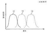
图12中的曲线141、142、143分别表示图11的太阳电池单元131、132、133的发电效率的光波长依赖性。太阳光具有宽的光谱,但在单接合的太阳电池单元中仅其一部分的波长带能够用于光电转换。因此,存在层叠具有不同的灵敏度波长带的多个太阳电池单元,而将宽的光谱用于光电转换的太阳电池单元。作为这样的层叠型太阳电池单元,大多数情况下使用高效率但高成本的化合物半导体。为了抑制昂贵的化合物半导体的使用量而低成本化,经常使用通过聚光透镜聚集太阳光来减小受光面积之后进行光电转换的方法。
在先技术文献prior art literature
专利文献patent documents
专利文献1:日本专利文献特开昭58-77262号公报Patent Document 1: Japanese Patent Application Laid-Open No. 58-77262
专利文献2:日本专利文献昭61-164272号公报Patent Document 2: Japanese Patent Document Sho 61-164272 Gazette
专利文献3:日本专利文献特开2002-151726号公报Patent Document 3: Japanese Patent Application Laid-Open No. 2002-151726
发明内容Contents of the invention
本发明所要解决的技术问题Technical problem to be solved by the present invention
另外,上述专利文献的全部公开内容通过援引被并入本文中。根据本发明的观点给出以下的分析。In addition, the entire disclosure content of the said patent document is incorporated here by reference. The following analysis is given from the viewpoint of the present invention.
在以往的层叠型太阳电池单元中,存在从受光面入射的光随着进入电池单元内部受到散射或吸收或边界面上的反射而被损失的问题。因此,存在不能提高发电效率的问题。In the conventional stacked solar cell, there is a problem that the light incident from the light receiving surface is lost as it enters the cell, is scattered or absorbed, or is reflected on the boundary surface. Therefore, there is a problem that the power generation efficiency cannot be improved.
本发明的主要的技术问题是提供能够实现光损失少的高效的发电的太阳光发电装置。The main technical problem of the present invention is to provide a photovoltaic power generation device capable of realizing high-efficiency power generation with little light loss.
用于解决技术问题的技术手段Technical means used to solve technical problems
在本发明的第一视点中,一种太阳光发电装置,所述太阳光发电装置在光学系统的焦点上配置有太阳电池单元,所述太阳光发电装置的特征在于,所述光学系统由一个光学系统构成,并且被构成为进行平行于所述光学系统的光轴入射的入射光的聚光以及光谱分离,并针对每个被进行了光谱分离的波长带光在所述光轴上的不同的位置上汇聚焦点,所述太阳电池单元具有在沿所述光轴配置的基板部的周围配置的接合部,所述接合部的表面为受光面,并且所述太阳电池单元具有灵敏度波长带不同的多个太阳电池单元,所述多个太阳电池单元沿所述光轴方向排列,并且被配置在汇聚与各个所述灵敏度波长带相对应的所述波长带光的所述焦点的位置上。In a first viewpoint of the present invention, a photovoltaic power generation device is provided with a solar cell unit at the focal point of an optical system, wherein the photovoltaic power generation device is characterized in that the optical system consists of a The optical system is configured, and is configured to perform condensing and spectral separation of incident light incident parallel to the optical axis of the optical system, and for each spectrally separated wavelength band light on the optical axis. The focal point is converged at the position, the solar battery unit has a joint portion arranged around the substrate portion arranged along the optical axis, the surface of the joint portion is a light-receiving surface, and the solar battery unit has different sensitivity wavelength bands. a plurality of solar battery cells arranged in the direction of the optical axis and arranged at the positions of the focal points that converge light of the wavelength bands corresponding to the respective sensitivity wavelength bands.
在本发明的所述太阳光发电装置中,优选地,所述基板部形成为沿所述光轴配置的圆柱体或柱体,所述接合部沿所述圆柱体或柱体的侧面形成为圆筒形或筒形。In the photovoltaic power generation device of the present invention, preferably, the substrate portion is formed as a cylinder or column arranged along the optical axis, and the joint portion is formed as a cylinder along a side surface of the cylinder or column. Cylindrical or tubular.
在本发明的所述太阳光发电装置中,优选地,所述基板部形成为其顶点朝向所述光学系统侧的圆锥体或锥体,所述接合部沿所述圆锥体或锥体的锥面形成为圆锥形或锥形。In the photovoltaic power generation device of the present invention, preferably, the substrate portion is formed as a cone or cone whose apex faces the optical system side, and the joint portion is formed along the cone of the cone or cone. The face is formed into a conical or tapered shape.
在本发明的所述太阳光发电装置中,优选地,所述光学系统是具有透镜部的菲涅耳透镜,所述透镜部包括具有与所述入射光平行的侧壁面的同心圆状的槽。In the photovoltaic power generation device of the present invention, preferably, the optical system is a Fresnel lens having a lens portion including a concentric circular groove having a side wall surface parallel to the incident light. .
在本发明的第二视点中,一种太阳光发电装置,所述太阳光发电装置在光学系统的焦点上配置有太阳电池单元,所述太阳光发电装置的特征在于,所述光学系统由一个光学系统构成,并且被构成为进行从与所述光学系统的光轴不平行的方向入射的入射光的聚光以及光谱分离,并针对每个被进行了光谱分离的波长带光在所述光轴以外的规定的线上的不同的位置上汇聚焦点,所述太阳电池单元在基板部的表面上具有平坦的接合部,所述接合部的表面为受光面,并且所述太阳电池单元具有灵敏度波长带不同的多个太阳电池单元,所述多个太阳电池单元沿所述规定的线的方向排列,并且被配置在汇聚与各个所述灵敏度波长带相对应的所述波长带光的所述焦点的位置上。In a second aspect of the present invention, a photovoltaic power generation device is provided with a solar cell unit at the focal point of an optical system, wherein the photovoltaic power generation device is characterized in that the optical system consists of a The optical system is configured, and is configured to perform condensing and spectral separation of incident light incident from a direction not parallel to the optical axis of the optical system, and for each spectrally separated wavelength band light in the light Converging focal points at different positions on a prescribed line other than the axis, the solar battery unit has a flat junction on the surface of the substrate, the surface of the junction is a light-receiving surface, and the solar battery unit has a sensitivity a plurality of solar battery cells having different wavelength bands, the plurality of solar battery cells are arranged in the direction of the predetermined line and arranged in the the position of the focus.
在本发明的所述太阳光发电装置中,优选地,所述光学系统是具有透镜部的菲涅耳透镜,所述透镜部包括具有与所述入射光平行的侧壁面的同心圆状的槽。In the photovoltaic power generation device of the present invention, preferably, the optical system is a Fresnel lens having a lens portion including a concentric circular groove having a side wall surface parallel to the incident light. .
在本发明的所述太阳光发电装置中,优选地,所述菲涅耳透镜在所述透镜部的相反面上具有平面部,所述平面部为与所述入射光垂直的面。In the photovoltaic power generation device of the present invention, preferably, the Fresnel lens has a plane portion on a surface opposite to the lens portion, and the plane portion is a plane perpendicular to the incident light.
在本发明的所述太阳光发电装置中,优选地,所述菲涅耳透镜在所述透镜部的相反面上具有至少一个台阶,所述台阶由与所述入射光垂直的平面部以及具有与所述入射光平行的侧壁面的槽构成。In the photovoltaic power generation device of the present invention, preferably, the Fresnel lens has at least one step on the opposite surface of the lens part, and the step consists of a plane part perpendicular to the incident light and a Grooves on the side wall surface parallel to the incident light are formed.
发明效果Invention effect
根据本发明,能够实现比以往的太阳光发电装置更高效的光电转换。其理由是:利用光学系统的色差(轴上色差、横向色差)使用一个光学系统进行聚光和光谱分解,并且将具有多个不同的灵敏度波长带的太阳电池单元排列在相对应的波长带光的焦点位置上。由此,所有的波长带光都在太阳电池单元的第一接合部(距离表面最近的接合部)上被进行光电转换。因此,与以往的使用层叠型太阳电池单元的太阳光发电装置相比,由入射光经过其他的太阳电池单元引起的损失消失,从而能够实现高效的太阳光发电。According to the present invention, it is possible to achieve more efficient photoelectric conversion than conventional photovoltaic power generation devices. The reason is: using the chromatic aberration of the optical system (axial chromatic aberration, lateral chromatic aberration) to use an optical system for light concentration and spectral decomposition, and to arrange solar cells with multiple different sensitivity wavelength bands in the corresponding wavelength band light on the focus position. Accordingly, light in all wavelength bands is photoelectrically converted at the first junction portion (junction portion closest to the surface) of the solar battery cell. Therefore, compared with a conventional solar power generation device using stacked solar cells, the loss caused by incident light passing through other solar cells is eliminated, and efficient photovoltaic power generation can be realized.
附图说明Description of drawings
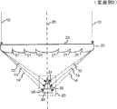
图1是示意性示出本发明的实施例1涉及的太阳光发电装置的构成的概略立体图。FIG. 1 is a schematic perspective view schematically showing the configuration of a photovoltaic power generation device according to
图2是示意性示出本发明的实施例1涉及的太阳光发电装置的构成的沿光轴剖开的剖面图。2 is a cross-sectional view taken along the optical axis schematically showing the configuration of the photovoltaic power generation device according to
图3是示意性示出本发明的实施例1涉及的太阳光发电装置中的太阳电池单元的构成的沿垂直于光轴的面剖开的剖面图。3 is a cross-sectional view schematically showing the structure of a solar battery cell in the photovoltaic power generation device according to Example 1 of the present invention, taken along a plane perpendicular to the optical axis.
图4是示意性示出本发明的实施例2涉及的太阳光发电装置的构成的沿光轴剖开的剖面图。4 is a cross-sectional view taken along the optical axis schematically showing the configuration of a photovoltaic power generation device according to
图5是示意性示出本发明的实施例3涉及的太阳光发电装置的构成的沿光轴剖开的剖面图。5 is a cross-sectional view taken along the optical axis schematically showing the configuration of a photovoltaic power generation device according to
图6是示意性示出本发明的实施例3涉及的太阳光发电装置中的太阳电池单元的构成的从受光面侧观察时的平面图。6 is a plan view schematically showing the configuration of a solar battery cell in a photovoltaic power generation device according to Example 3 of the present invention, viewed from the light-receiving surface side.
图7是示意性示出本发明的实施例4涉及的太阳光发电装置的构成的沿光轴剖开的剖面图。7 is a cross-sectional view taken along the optical axis schematically showing the configuration of a photovoltaic power generation device according to Embodiment 4 of the present invention.
图8是示意性示出本发明的实施例4涉及的太阳光发电装置中的菲涅耳透镜的构成的概略立体图。8 is a schematic perspective view schematically showing the configuration of a Fresnel lens in a photovoltaic power generation device according to Embodiment 4 of the present invention.
图9是示意性示出本发明的实施例5涉及的太阳光发电装置的构成的沿光轴剖开的剖面图。9 is a cross-sectional view taken along the optical axis schematically showing the configuration of a photovoltaic power generation device according to Embodiment 5 of the present invention.
图10是示意性示出本发明的实施例5涉及的太阳光发电装置中的菲涅耳透镜的构成的从入射光侧观察时的平面图。10 is a plan view schematically showing the configuration of a Fresnel lens in a photovoltaic power generation device according to Embodiment 5 of the present invention, viewed from the incident light side.
图11是示意性示出以往例子涉及的太阳光发电装置的构成的沿光轴剖开的剖面图。Fig. 11 is a cross-sectional view taken along the optical axis schematically showing the configuration of a photovoltaic power generation device according to a conventional example.
图12是示意性示出以往例子涉及的太阳光发电装置中的太阳电池单元的发电效率的光波长依赖性的图。12 is a graph schematically showing the light wavelength dependence of the power generation efficiency of a solar battery cell in a solar power generation device according to a conventional example.
具体实施方式Detailed ways
在本发明的实施方式1涉及的太阳光发电装置中,在光学系统(图2和图4的20)的焦点上配置有太阳电池单元(图2和图4的30)的太阳光发电装置中,所述光学系统由一个光学系统构成,并且被构成为进行平行于所述光学系统的光轴(图2和图4的25)入射的入射光(图2和图4的10)的聚光以及光谱分离,并针对每个被进行了光谱分离的波长带光(图2和图4的12、13、14)在所述光轴上的不同的位置上汇聚焦点,所述太阳电池单元具有在沿所述光轴配置的基板部(图3的36)的周围配置的接合部(图3的37),所述接合部的表面为受光面(图2和图4的35),并且所述太阳电池单元具有灵敏度波长带不同的多个太阳电池单元(图2和图4的31、32、33),所述多个太阳电池单元沿所述光轴方向排列,并且被配置在汇聚与各个所述灵敏度波长带相对应的所述波长带光的所述焦点的位置上。In the photovoltaic power generation device according to Embodiment 1 of the present invention, in the photovoltaic power generation device in which the solar cell (30 in FIG. 2 and FIG. 4 ) is arranged at the focal point of the optical system (20 in FIGS. 2 and 4 ) , the optical system is composed of one optical system, and is configured to condense the incident light (10 in Fig. 2 and Fig. 4 ) incident parallel to the optical axis (25 in Fig. 2 and Fig. 4 ) of the optical system And spectral separation, and for each spectrally separated wavelength band light (12, 13, 14 in Fig. 2 and Fig. 4) converges focal points on different positions on the optical axis, the solar cell unit has The joint portion (37 in FIG. 3 ) disposed around the substrate portion (36 in FIG. 3 ) disposed along the optical axis, the surface of the joint portion is a light receiving surface (35 in FIGS. 2 and 4 ), and the The solar cell unit has a plurality of solar cell units (31, 32, 33 in Fig. 2 and Fig. 4 ) with different sensitivity wavelength bands, the plurality of solar cell units are arranged along the direction of the optical axis, and are arranged between converging and Each of the sensitivity wavelength bands corresponds to the position of the focal point of the light in the wavelength band.
在本发明的实施方式2涉及的太阳光发电装置中,在光学系统(图5、图7、图9的20)的焦点上配置有太阳电池单元(图5、图7、图9的30)的太阳光发电装置中,所述光学系统由一个光学系统构成,并且被构成为进行从与所述光学系统的光轴(图5、图7、图9的25)不平行的方向入射的入射光(图5、图7、图9的10)的聚光以及光谱分离,并针对每个被进行了光谱分离的波长带光(图5、图7、图9的12、13、14)在所述光轴以外的规定的线上的不同的位置上汇聚焦点,所述太阳电池单元在基板部(相当于图3的36的部分)的表面上具有平坦的接合部(相当于图3的37的部分),所述接合部的表面为受光面(图5、图7、图9的35),并且所述太阳电池单元具有灵敏度波长带不同的多个太阳电池单元(图5、图7、图9的31、32、33),所述多个太阳电池单元沿所述规定的线的方向排列,并且被配置在汇聚与各个所述灵敏度波长带相对应的所述波长带光的所述焦点的位置上。In the photovoltaic power generation device according to
另外,在本申请中标注附图标记的情况下,这些附图标记专门用于帮助理解,而不限定于图示的方式。In addition, when a code|symbol is attached|subjected in this application, these code|symbol is used exclusively for helping understanding, and is not limited to the form of illustration.
实施例1Example 1
使用附图对本发明的实施例1涉及的太阳光发电装置进行说明。图1是示意性示出本发明的实施例1涉及的太阳光发电装置的构成的概略立体图。图2是示意性示出本发明的实施例1涉及的太阳光发电装置的构成的沿光轴剖开的剖面图。图3是示意性示出本发明的实施例1涉及的太阳光发电装置中的太阳电池单元的构成的沿垂直于光轴的面剖开的剖面图。A photovoltaic power generation device according to
参照图1,太阳光发电装置是在聚光透镜20的焦点上配置有太阳电池单元30的聚光型的太阳光发电装置。Referring to FIG. 1 , the photovoltaic power generation device is a concentrating type photovoltaic power generation device in which a
聚光透镜20是对平行于光轴25入射的太阳光10进行聚光的透镜。聚光透镜20是具有聚光功能和光谱分离功能的透镜,例如,优选使用轻量且廉价的菲涅耳透镜。聚光透镜20的入射侧的面为平面部23,聚光透镜20的射出侧(太阳电池单元30侧)的面为在中央侧凸出的凸面,并且聚光透镜20在凸面中具有以光轴25为中心的同心圆状的槽21(参照图2)。槽21的槽数在图2中为三个,但也可以为其他数量。另外,对于聚光透镜20,在图1中示出了圆形的聚光透镜的例子,但也可以是方形的透镜。另外,对于聚光透镜20,在图2中将入射侧的面作为平面部23,但也可以翻转聚光透镜20而将射出侧(太阳电池单元30侧)的面作为平面部23。The condensing
平行于聚光透镜20的光轴25入射的太阳光10经过聚光透镜20而被聚光。图1中的聚光11在实际中产生轴上色差因而焦点未汇聚于一点。经过了聚光透镜20的聚光11因轴上色差被分为各波长带光,各波长带光在光轴25上的不同的位置上汇聚焦点。在图2中示出了这种情况。各波长带光的焦点从聚光透镜20侧以短波长带光12的焦点、中波长带光13的焦点、长波长带光14的焦点的顺序配置。如此,光根据波长在光轴25上的不同的位置上汇聚焦点的现象作为轴上色差而公知。The
太阳电池单元30是利用光伏效应将光能直接转换成电力的装置。太阳电池单元30被配置在经过了聚光透镜20的聚光11的焦点上。太阳电池单元30在聚光透镜20的光轴25的周围具有小径的圆筒形状的受光面35。太阳电池单元30包括沿光轴25方向排列的多个太阳电池单元31、32、33。短波长带太阳电池单元31是在短波长区域具有灵敏度波长带的太阳电池单元,并且被配置在短波长带光12的焦点上。中波长带太阳电池单元32是在中波长区域具有灵敏度波长带的太阳电池单元,并且被配置在中波长带光13的焦点上。长波长带太阳电池单元33是在长波长区域具有灵敏度波长带的太阳电池单元,并且被配置在长波长带光14的焦点上。太阳电池单元31、32、33的各个外周面构成直接的受光面35。The
太阳电池单元30(图2的太阳电池单元31、32、33)具有沿聚光透镜(图2的20)的光轴25的基板部36,在基板部36的周围具有接合部37,在接合部37的表面上具有受光面35(参照图3)。基板部36被形成为沿光轴25配置的圆柱体(也可以是柱体)。接合部37沿圆柱体(也可以是柱体)的侧面形成为圆筒形(也可以是筒形)。由于在太阳电池单元(图2的31、32、33)的各个受光面35正下方的接合部37进行光电转换,因此不存在像以往那样由经过其他的太阳电池单元引起的损失,由此能够实现高效率的光电转换。另外,由于构成聚光11的焦点的光轴25附近相当于太阳电池单元30的基板部36,因此构成聚光11的焦点的光轴25附近不能用于光电转换。但是,通过充分地缩小太阳电池单元30的受光面35的直径,能够减轻该影响。The solar battery unit 30 (
受光面35在光轴25的周围形成为圆筒形(也可以是筒形),并且在与光轴25垂直的剖面中受光面35垂直地面向聚光11(图2的各波长带光12、13、14),但在图2所示的沿光轴25剖开的剖面中受光面35与各波长带光12、13、14(图3的11)不垂直。因此,为了减轻受光面35上的聚光11的反射损失,优选地,充分地缩短聚光透镜20的焦点距离,从而使聚光11以尽可能接近垂直于受光面35的角度入射。The light-receiving
根据实施例1,能够实现比以往的太阳光发电装置更高效的光电转换。其理由是因为:利用聚光透镜20的色差通过一个聚光透镜20进行聚光和光谱分解,并且将具有多个不同的灵敏度波长带的太阳电池单元31、32、33排列在相对应的波长带光的焦点位置上。由此,所有的波长带光在太阳电池单元31、32、33的接合部37上被进行光电转换。因此,与使用以往的层叠型的太阳电池单元的太阳光发电装置相比,由入射光经过其他的太阳电池单元引起的损失消失,从而能够实现高效率的太阳光发电。另外,由于一个聚光透镜20兼备聚光和光谱分离的功能,因此与分别具备聚光用光学系统和光谱分离用光学系统的装置相比,具有能够实现光损失少的高效的太阳光发电装置的优点。According to Example 1, it is possible to realize photoelectric conversion more efficiently than conventional photovoltaic power generation devices. The reason is because: the chromatic aberration of the
实施例2Example 2
使用附图对本发明的实施例2涉及的太阳光发电装置进行说明。图4是示意性示出本发明的实施例2涉及的太阳光发电装置的构成的沿光轴剖开的剖面图。A photovoltaic power generation device according to
实施例2是实施例1的变形例,其取代将太阳电池单元30形成为圆筒体,而将太阳电池单元30形成为顶点面向聚光透镜20侧的圆锥体(也可以是锥体)。太阳电池单元30的与光轴25垂直的截面除圆锥的顶点以外,与图3(实施例1)相同。其他的构成与实施例1相同。
在沿光轴25剖开的剖面中观察时,与实施例1涉及的圆筒形的受光面(图2的35)相比,实施例2涉及的圆锥形的受光面35相对于各波长带光12、13、14的行进方向更接近垂直,因此具有能够抑制反射的优点。受光面35的圆锥面和光轴25所成的角度越大,聚光的光谱分离越模糊,焦点也不会汇聚。另一方面,受光面35的圆锥面和光轴25所成的角度越大,聚光的入射角越小。即,由于聚光(各波长带光12、13、14)以更接近垂直于受光面35的角度入射,因此由反射引起的损失减小。兼顾考虑这两个因素,受光面35的圆锥面和光轴25所成的角度被设定为使发电效率最高。Compared with the cylindrical light-receiving surface (35 in FIG. 2 ) according to Example 1, the conical light-receiving
根据实施例2,实现与实施例1同样的效果,并且通过将受光面35形成为圆锥面,聚光(各波长带光12、13、14)以更接近垂直于受光面35的角度入射,因此由反射引起的损失小,由此能够实现比实施例1更高效率的太阳光发电。According to
实施例3Example 3
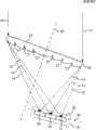
使用附图对本发明的实施例3涉及的太阳光发电装置进行说明。图5是示意性示出本发明的实施例3涉及的太阳光发电装置的构成的沿光轴剖开的剖面图。图6是示意性示出本发明的实施例3涉及的太阳光发电装置中的太阳电池单元的构成的从受光面侧观察时的平面图。A photovoltaic power generation device according to
实施例3是实施例1的变形例,其将聚光透镜20的光轴25配置成相对于太阳光10倾斜一定角度,使得在光轴25以外的规定的线34上的不同的位置上汇聚各波长带光12、13、14的焦点,并且与各波长带光12、13、14的焦点相匹配地将在各波长带具有灵敏度的太阳电池单元33、32、31的受光面35配置成直线状。实施例3的其他的构成与实施例1相同。
聚光透镜20是对平行于光轴25入射的太阳光10进行聚光的透镜。聚光透镜20是具有聚光功能和光谱分离功能的透镜,例如,优选使用轻量且廉价的菲涅耳透镜。聚光透镜20的入射侧的面为平面部23,聚光透镜20的射出侧(太阳电池单元30侧)的面为在中央侧凸出的凸面,并且聚光透镜20在凸面中具有以光轴25为中心的同心圆状的槽21。槽21的槽数在图5中为三个,但也可以为其他数量。另外,在通常的菲涅耳透镜中,由于以从光轴25偏离的角度入射的太阳光10在槽21中被反射或散射,因此存在损失增大的问题。因此,在实施例3中,对于聚光透镜20,优选使用如图5所示使槽21的侧壁面平行于入射光10也就是使槽21的侧壁面与光轴25成一定的角度的菲涅耳透镜。由此,能够抑制入射的太阳光10在槽21中被反射或散射。The condensing
聚光透镜20的光轴25相对于入射来的太阳光10倾斜一定角度。此时,由于横向色差,经过了聚光透镜20的光被进行光谱分离,并根据每个波长带光被聚光于不同的位置,由此在规定的位置上汇聚焦点。与实施例1、2的轴上色差的情况不同,在实施例3的横向色差中,各波长带光12、13、14的焦点位于规定的直线上(太阳电池单元30的受光面35上),而不位于光轴25上。The
太阳电池单元30是利用光伏效应将光能直接转换成电力的装置。太阳电池单元30被配置在经过了聚光透镜20的各波长带光12、13、14的焦点上。太阳电池单元30包括多个太阳电池单元31、32、33,并且在各波长带光12、13、14上具有灵敏度的太阳电池单元33、32、31的受光面35被配置成直线状(参照图6)。短波长带太阳电池单元31是在短波长区域上具有灵敏度波长带的太阳电池单元,并且被配置在短波长带光12的焦点上。中波长带太阳电池单元32是在中波长区域上具有灵敏度波长带的太阳电池单元,并且配置在中波长带光13的焦点上。长波长带太阳电池单元33是在长波长区域上具有灵敏度波长带的太阳电池单元,并且被配置在长波长带光14的焦点上。太阳电池单元31、32、33的各自的聚光透镜20侧的平面构成直接的受光面35。The
太阳电池单元30(太阳电池单元31、32、33)具有平板状的基板部(未图示),在该基板部的聚光透镜20侧的面上具有平坦的接合部(未图示),在该接合部的表面上具有平坦的受光面35。由于在太阳电池单元31、32、33的各自的受光面35正下方的接合部上进行光电转换,因此不存在像以往那样由于经过其他的太阳电池单元引起的损失,由此能够实现高效率的光电转换。另外,受光面35能够以接近于垂直于各波长带光12、13、14的角度配置,因此具有反射损失少的优点。The solar battery unit 30 (
根据实施例3,实现与实施例1同样的效果,其通过聚光透镜20使用廉价且轻量的菲涅耳透镜,并使菲涅耳透镜的槽21的侧壁面与太阳光10平行,从而即使使用槽21相对于光轴25倾斜了角度T的菲涅耳透镜,也能够抑制由散射或反射引起的损失。According to
实施例4Example 4
使用附图对本发明的实施例4涉及的太阳光发电装置进行说明。图7是示意性示出本发明的实施例4涉及的太阳光发电装置的构成的沿光轴剖开的剖面图。图8是示意性示出本发明的实施例4涉及的太阳光发电装置中的菲涅耳透镜的构成的概略立体图。A photovoltaic power generation device according to Embodiment 4 of the present invention will be described with reference to the drawings. 7 is a cross-sectional view taken along the optical axis schematically showing the configuration of a photovoltaic power generation device according to Embodiment 4 of the present invention. 8 is a schematic perspective view schematically showing the configuration of a Fresnel lens in a photovoltaic power generation device according to Embodiment 4 of the present invention.
实施例4是实施例3的变形例,并且使用了入射侧的平面部23形成为垂直于入射太阳光10的聚光透镜20。另外,聚光透镜20的射出侧(太阳电池单元30侧)的透镜部24为在聚光透镜20的光轴25相对于太阳光10倾斜了一定角度的状态下在中央侧凸出的凸面,并且在凸面中具有以光轴25为中心的同心圆状的槽21,这方面与实施例3的聚光透镜(图5的20)相同,其他的构成与实施例3相同。Embodiment 4 is a modified example of
根据实施例4,实现与实施例3同样的效果。另外,如果像实施例3(参照图5)那样聚光透镜(图5的20)的入射侧的平面部(图5的23)相对于太阳光(图5的10)倾斜,则平面部(图5的23)上的反射损失有可能增大,但通过使用如实施例4(参照图7)那样平面部23与入射太阳光10垂直的聚光透镜20,能够抑制该反射损失。According to the fourth embodiment, the same effect as that of the third embodiment is achieved. In addition, if the plane portion (23 in FIG. 5 ) on the incident side of the condenser lens (20 in FIG. 5 ) is inclined relative to the sunlight (10 in FIG. 5 ) as in Example 3 (see FIG. 5 ), the plane portion (20 in FIG. The reflection loss at 23) in FIG. 5 may increase, but this reflection loss can be suppressed by using the
实施例5Example 5
使用附图对本发明的实施例5涉及的太阳光发电装置进行说明。图9是示意性示出本发明的实施例5涉及的太阳光发电装置的构成的沿光轴剖开的剖面图。图10是示意性示出本发明的实施例5涉及的太阳光发电装置中的菲涅耳透镜的构成的从入射光侧观察时的平面图。A photovoltaic power generation device according to Embodiment 5 of the present invention will be described with reference to the drawings. 9 is a cross-sectional view taken along the optical axis schematically showing the configuration of a photovoltaic power generation device according to Embodiment 5 of the present invention. 10 is a plan view schematically showing the configuration of a Fresnel lens in a photovoltaic power generation device according to Embodiment 5 of the present invention, viewed from the incident light side.
实施例5是实施例3的变形例,并且使用了下述的聚光透镜20:使入射侧的面作为整体倾斜一定角度而形成台阶状,并且形成了槽22使得平面部23与入射的太阳光10垂直并且台阶部的侧壁面与入射的太阳光10平行。在槽22之间具有条状的平面部23(参照图10)。聚光透镜20中的条状的平面部23的数量可以为任意数量。另外,聚光透镜20的射出侧(太阳电池单元30侧)的面为在聚光透镜20的光轴25相对于太阳光10倾斜了一定角度的状态下在中央侧凸出的凸面,并且在凸面中具有以光轴25为中心的同心圆状的槽21,这方面与实施例3的聚光透镜(图5的20)相同。其他的构成与实施例3相同。Embodiment 5 is a modified example of
根据实施例5,实现与实施例3相同的效果,并且由于入射的太阳光10向与其垂直的平面部23入射,因此具有抑制反射损失的优点。另外,与实施例4相比,用于聚光透镜20的材料的量较少,因此聚光透镜20具有廉价且轻量的优点。另外,在聚光透镜20中,光所经过的介质的厚度被削减,因此还具有减少介质中的光损失的优点。According to the fifth embodiment, the same effect as that of the third embodiment is achieved, and since the
另外,实施例1至5中的聚光透镜20不限于圆形,例如,也可以是方形。另外,构成实施例1至5中的太阳电池单元30的、具有不同的灵敏度波长带的太阳电池单元的数量可以是任意的数量,只要大于等于两个即可。并且,上面用于说明的各波长带光的焦点位置的顺序、各灵敏度波长带的太阳电池单元的顺序仅是一个例子。根据透镜材质等条件,可改变这些顺序,但其不改变本发明的本质。In addition, the condensing
在本发明的全部公开(包括权利要求书)的范围内,可进一步基于本发明的基本的技术思想进行实施方式或实施例的变更和调整。另外,在本发明的权利要求书的范围内可进行各种公开要素的各种各样的组合或选择。即,本发明当然包括本领域技术人员根据包括权利要求的全部公开和技术思想可以作出的各种变形和修改。Within the scope of the entire disclosure of the present invention (including the claims), modifications and adjustments to the embodiments or examples can be made further based on the basic technical idea of the present invention. In addition, various combinations and selections of various disclosed elements are possible within the scope of the claims of the present invention. That is, the present invention naturally includes various variations and modifications that can be made by those skilled in the art based on the entire disclosure and technical ideas including the claims.
符号说明Symbol Description
10 太阳光(入射光)10 Sunlight (incident light)
11 聚光11 Spotlight
12 短波长带光(波长带光)12 Short wavelength band light (wavelength band light)
13 中波长带光(波长带光)13 Medium wavelength band light (wavelength band light)
14 高波长带光(波长带光)14 High wavelength band light (wavelength band light)
20、120 聚光透镜(光学系统)20, 120 Condensing lens (optical system)
21、121 槽21, 121 slots
22 槽22 slots
23 平面部23 plane part
24 透镜部24 Lens Department
25、125 光轴25, 125 optical axis
30、130 太阳电池单元30, 130 solar cell units
31、131 短波长带太阳电池单元31, 131 short wavelength band solar cell unit
32、132 中波长带太阳电池单元32, 132 mid-wavelength band solar cell unit
33、133 长波长带太阳电池单元33, 133 long wavelength band solar cell unit
34 规定的线34 prescribed lines
35 受光面35 light-receiving surface
36 基板部36 Substrate part
37 接合部37 joint
139 受光面139 light-receiving surface
141、142、143 发电效率141, 142, 143 Power generation efficiency
Claims (8)
Applications Claiming Priority (3)
| Application Number | Priority Date | Filing Date | Title |
|---|---|---|---|
| JP2009285435 | 2009-12-16 | ||
| JP2009-285435 | 2009-12-16 | ||
| PCT/JP2010/072382WO2011074535A1 (en) | 2009-12-16 | 2010-12-13 | Solar power generation apparatus |
Publications (1)
| Publication Number | Publication Date |
|---|---|
| CN102668127Atrue CN102668127A (en) | 2012-09-12 |
Family
ID=44167287
Family Applications (1)
| Application Number | Title | Priority Date | Filing Date |
|---|---|---|---|
| CN2010800574701APendingCN102668127A (en) | 2009-12-16 | 2010-12-13 | Solar power generation apparatus |
Country Status (5)
| Country | Link |
|---|---|
| US (1) | US20120247534A1 (en) |
| EP (1) | EP2515351A1 (en) |
| JP (1) | JP5811846B2 (en) |
| CN (1) | CN102668127A (en) |
| WO (1) | WO2011074535A1 (en) |
Cited By (1)
| Publication number | Priority date | Publication date | Assignee | Title |
|---|---|---|---|---|
| CN109891602A (en)* | 2016-10-14 | 2019-06-14 | 株式会社钟化 | Photovoltaic installation |
Families Citing this family (10)
| Publication number | Priority date | Publication date | Assignee | Title |
|---|---|---|---|---|
| JP5165157B2 (en)* | 2010-12-01 | 2013-03-21 | パナソニック株式会社 | Fresnel fly-eye microlens array for focusing on solar cells |
| JPWO2012161332A1 (en)* | 2011-05-24 | 2014-07-31 | 日本電気株式会社 | Concentrating solar power generator |
| US9000290B2 (en)* | 2011-10-03 | 2015-04-07 | The Boeing Company | Multi sensor solar collection system |
| WO2013191785A1 (en)* | 2012-06-21 | 2013-12-27 | Alfred Jost | Solar module |
| WO2014037757A1 (en)* | 2012-09-07 | 2014-03-13 | Doci Innovations GmbH | Concentrator system for converting light into electrical energy |
| US20150244312A1 (en)* | 2012-10-03 | 2015-08-27 | Nec Corporation | Power converter, solar energy device and solar energy power conversion method |
| JP2015231016A (en)* | 2014-06-06 | 2015-12-21 | Tdk株式会社 | solar battery |
| US11302839B2 (en)* | 2017-07-19 | 2022-04-12 | The Regents Of The University Of Michigan | Integrated micro-lens for photovoltaic cell and thermal applications |
| GB2576212B (en)* | 2018-08-10 | 2021-12-29 | X Fab Semiconductor Foundries Gmbh | Improvements in lens layers for semiconductor devices |
| WO2024157371A1 (en)* | 2023-01-25 | 2024-08-02 | 日本電信電話株式会社 | Solar battery module and conversion device |
Citations (3)
| Publication number | Priority date | Publication date | Assignee | Title |
|---|---|---|---|---|
| US4204881A (en)* | 1978-10-02 | 1980-05-27 | Mcgrew Stephen P | Solar power system |
| US4418238A (en)* | 1981-10-20 | 1983-11-29 | Lidorenko Nikolai S | Photoelectric solar cell array |
| CN101083288A (en)* | 2007-06-12 | 2007-12-05 | 邱定平 | Spectral solar energy photocell |
Family Cites Families (8)
| Publication number | Priority date | Publication date | Assignee | Title |
|---|---|---|---|---|
| JPS5877262A (en) | 1981-10-20 | 1983-05-10 | ビクト−ル・フオスカノウイツチ・アフイアン | Solar battery |
| US4427839A (en)* | 1981-11-09 | 1984-01-24 | General Electric Company | Faceted low absorptance solar cell |
| JPS61164272A (en) | 1985-01-17 | 1986-07-24 | Nec Corp | Condenser type solar power generator |
| JP2666142B2 (en) | 1987-02-04 | 1997-10-22 | 旭光学工業株式会社 | Automatic focus detection device for camera |
| JPS6446751A (en) | 1987-08-14 | 1989-02-21 | Konishiroku Photo Ind | Silver halide photographic sensitive material |
| US5517339A (en)* | 1994-06-17 | 1996-05-14 | Northeast Photosciences | Method of manufacturing high efficiency, broad bandwidth, volume holographic elements and solar concentrators for use therewith |
| KR100657949B1 (en)* | 2005-02-05 | 2006-12-14 | 삼성전자주식회사 | Cylindrical soft solar cell and manufacturing method thereof |
| US20090250095A1 (en)* | 2008-04-05 | 2009-10-08 | Brent Perry Thorley | Low-profile solar tracking module |
- 2010
- 2010-12-13CNCN2010800574701Apatent/CN102668127A/enactivePending
- 2010-12-13JPJP2011546109Apatent/JP5811846B2/ennot_activeExpired - Fee Related
- 2010-12-13USUS13/515,473patent/US20120247534A1/ennot_activeAbandoned
- 2010-12-13WOPCT/JP2010/072382patent/WO2011074535A1/enactiveApplication Filing
- 2010-12-13EPEP10837561Apatent/EP2515351A1/ennot_activeWithdrawn
Patent Citations (3)
| Publication number | Priority date | Publication date | Assignee | Title |
|---|---|---|---|---|
| US4204881A (en)* | 1978-10-02 | 1980-05-27 | Mcgrew Stephen P | Solar power system |
| US4418238A (en)* | 1981-10-20 | 1983-11-29 | Lidorenko Nikolai S | Photoelectric solar cell array |
| CN101083288A (en)* | 2007-06-12 | 2007-12-05 | 邱定平 | Spectral solar energy photocell |
Cited By (1)
| Publication number | Priority date | Publication date | Assignee | Title |
|---|---|---|---|---|
| CN109891602A (en)* | 2016-10-14 | 2019-06-14 | 株式会社钟化 | Photovoltaic installation |
Also Published As
| Publication number | Publication date |
|---|---|
| US20120247534A1 (en) | 2012-10-04 |
| JPWO2011074535A1 (en) | 2013-04-25 |
| EP2515351A1 (en) | 2012-10-24 |
| JP5811846B2 (en) | 2015-11-11 |
| WO2011074535A1 (en) | 2011-06-23 |
Similar Documents
| Publication | Publication Date | Title |
|---|---|---|
| CN102668127A (en) | Solar power generation apparatus | |
| US20070227581A1 (en) | Concentrator solar cell module | |
| JP2009188410A5 (en) | ||
| WO2013147008A1 (en) | Secondary lens, solar cell mounting body, light gathering solar energy unit, light gathering solar energy device, and light gathering solar energy module | |
| US20130153000A1 (en) | Multi-band light collection and energy conversion module | |
| JP2013545260A (en) | Focused solar induction module | |
| KR100933213B1 (en) | Condensing Lens for Solar Power Generation | |
| CN104124301B (en) | Solar concentrating system | |
| CN105144395A (en) | Spectral light splitting module and photovoltaic system including concentrator optics | |
| CN114400265A (en) | Photoelectric conversion device for solar photovoltaic power generation | |
| US20090320901A1 (en) | Concentration photovoltaic cell system with light guide | |
| WO2012026572A1 (en) | Light-condensing device, light power generation device, and photothermal conversion device | |
| JP6694072B2 (en) | Photovoltaic device | |
| US9236517B2 (en) | Solar concentrator assembly having a converging element to converge the multiple light beams with different wavelengths from a sunlight splitting element | |
| WO2012161332A1 (en) | Concentrated solar power generation device | |
| JP6670991B2 (en) | Solar cell | |
| KR101469583B1 (en) | Apparatus for condensing sunlight | |
| JP2015207570A (en) | Light collection type photovoltaic power generation device | |
| JP2012009846A (en) | Light condensing-type photovoltaic power generation apparatus | |
| US20160284912A1 (en) | Photovoltaic cell | |
| KR100991986B1 (en) | Solar cell | |
| WO2012033132A1 (en) | Light condenser, photovoltaic system, and photothermal converter | |
| KR102378110B1 (en) | Concentrated solar ray generation device and method for solar ray generation using the same | |
| JP2016181678A5 (en) | ||
| JP2015015336A (en) | Condensation type solar cell |
Legal Events
| Date | Code | Title | Description |
|---|---|---|---|
| C06 | Publication | ||
| PB01 | Publication | ||
| C10 | Entry into substantive examination | ||
| SE01 | Entry into force of request for substantive examination | ||
| AD01 | Patent right deemed abandoned | Effective date of abandoning:20161019 | |
| C20 | Patent right or utility model deemed to be abandoned or is abandoned |