CN102667542A - Optical sheet and surface light source device - Google Patents
Optical sheet and surface light source deviceDownload PDFInfo
- Publication number
- CN102667542A CN102667542ACN2010800590329ACN201080059032ACN102667542ACN 102667542 ACN102667542 ACN 102667542ACN 2010800590329 ACN2010800590329 ACN 2010800590329ACN 201080059032 ACN201080059032 ACN 201080059032ACN 102667542 ACN102667542 ACN 102667542A
- Authority
- CN
- China
- Prior art keywords
- light
- layer
- optical sheet
- diffusing
- base material
- Prior art date
- Legal status (The legal status is an assumption and is not a legal conclusion. Google has not performed a legal analysis and makes no representation as to the accuracy of the status listed.)
- Granted
Links
Images


Classifications
- G—PHYSICS
- G02—OPTICS
- G02B—OPTICAL ELEMENTS, SYSTEMS OR APPARATUS
- G02B5/00—Optical elements other than lenses
- G02B5/02—Diffusing elements; Afocal elements
- G02B5/0205—Diffusing elements; Afocal elements characterised by the diffusing properties
- G02B5/021—Diffusing elements; Afocal elements characterised by the diffusing properties the diffusion taking place at the element's surface, e.g. by means of surface roughening or microprismatic structures
- G02B5/0231—Diffusing elements; Afocal elements characterised by the diffusing properties the diffusion taking place at the element's surface, e.g. by means of surface roughening or microprismatic structures the surface having microprismatic or micropyramidal shape
- G—PHYSICS
- G02—OPTICS
- G02F—OPTICAL DEVICES OR ARRANGEMENTS FOR THE CONTROL OF LIGHT BY MODIFICATION OF THE OPTICAL PROPERTIES OF THE MEDIA OF THE ELEMENTS INVOLVED THEREIN; NON-LINEAR OPTICS; FREQUENCY-CHANGING OF LIGHT; OPTICAL LOGIC ELEMENTS; OPTICAL ANALOGUE/DIGITAL CONVERTERS
- G02F1/00—Devices or arrangements for the control of the intensity, colour, phase, polarisation or direction of light arriving from an independent light source, e.g. switching, gating or modulating; Non-linear optics
- G02F1/01—Devices or arrangements for the control of the intensity, colour, phase, polarisation or direction of light arriving from an independent light source, e.g. switching, gating or modulating; Non-linear optics for the control of the intensity, phase, polarisation or colour
- G02F1/13—Devices or arrangements for the control of the intensity, colour, phase, polarisation or direction of light arriving from an independent light source, e.g. switching, gating or modulating; Non-linear optics for the control of the intensity, phase, polarisation or colour based on liquid crystals, e.g. single liquid crystal display cells
- G02F1/133—Constructional arrangements; Operation of liquid crystal cells; Circuit arrangements
- G02F1/1333—Constructional arrangements; Manufacturing methods
- G02F1/1335—Structural association of cells with optical devices, e.g. polarisers or reflectors
- G02F1/1336—Illuminating devices
- G02F1/133602—Direct backlight
- G02F1/133606—Direct backlight including a specially adapted diffusing, scattering or light controlling members
- G02F1/133607—Direct backlight including a specially adapted diffusing, scattering or light controlling members the light controlling member including light directing or refracting elements, e.g. prisms or lenses
- H—ELECTRICITY
- H10—SEMICONDUCTOR DEVICES; ELECTRIC SOLID-STATE DEVICES NOT OTHERWISE PROVIDED FOR
- H10K—ORGANIC ELECTRIC SOLID-STATE DEVICES
- H10K50/00—Organic light-emitting devices
- H10K50/80—Constructional details
- H10K50/85—Arrangements for extracting light from the devices
- H10K50/858—Arrangements for extracting light from the devices comprising refractive means, e.g. lenses
Landscapes
- Physics & Mathematics (AREA)
- Nonlinear Science (AREA)
- General Physics & Mathematics (AREA)
- Optics & Photonics (AREA)
- Mathematical Physics (AREA)
- Chemical & Material Sciences (AREA)
- Crystallography & Structural Chemistry (AREA)
- Optical Elements Other Than Lenses (AREA)
- Planar Illumination Modules (AREA)
- Electroluminescent Light Sources (AREA)
Abstract
Translated fromChineseDescription
Translated fromChinese技术领域technical field
本发明涉及光学片材及具备有机电致发光(下面称为“有机EL”)元件的面光源装置。The present invention relates to an optical sheet and a surface light source device including an organic electroluminescent (hereinafter referred to as "organic EL") element.
背景技术Background technique
目前正在研究使用在多层电极间设置有机发光层从而获得电致发光的有机EL元件作为代替液晶盒的显示元件。另外,还在研究将其作为平面型照明、液晶显示装置用背光灯等面光源装置的有机EL装置使用,该有机EL装置充分利用了其高发光效率、低电压驱动、轻量、低成本等特征。The use of an organic EL element in which electroluminescence is obtained by disposing an organic light-emitting layer between multilayer electrodes is currently being studied as a display element instead of a liquid crystal cell. In addition, it is also being studied as an organic EL device for surface light source devices such as planar lighting and backlights for liquid crystal display devices. This organic EL device makes full use of its high luminous efficiency, low voltage drive, light weight, and low cost. feature.
将有机EL元件用作面光源装置的光源时,高效地从元件中导出有用的形态的光是一个问题。例如,虽然有机EL元件的发光层本身发光效率较高,但是,其在透过构成元件的层叠结构直到出光的期间,由于层中发生干涉等,光量会降低,因此,寻求尽可能降低这种光的损失的方法。When an organic EL element is used as a light source of a surface light source device, it is a problem to efficiently extract light in a useful form from the element. For example, although the light-emitting layer itself of an organic EL element has a high luminous efficiency, the amount of light decreases due to interference in the layer during the period from passing through the laminated structure constituting the element until light is emitted. The method of light loss.
作为用于提高光导出效率的方法,已知在比光源装置更靠近光导出面侧设置各种凹凸结构的方法(例如专利文献1的图4、图6等)。作为这种具有凹凸结构的有机EL元件的部件,已知有包含通过所谓的光聚合物法(2P法)形成了凹凸结构的层的光学片材。As a method for improving light extraction efficiency, there is known a method of providing various concavo-convex structures on the side closer to the light extraction surface than the light source device (for example, FIG. 4 and FIG. 6 of Patent Document 1). As a member of such an organic EL element having a concavo-convex structure, an optical sheet including a layer having a concavo-convex structure formed by a so-called photopolymer method (2P method) is known.
现有技术文献prior art literature
专利文献patent documents
专利文献1:(日本)特开2009-266429号公报Patent Document 1: (Japanese) Unexamined Patent Application Publication No. 2009-266429
发明的内容content of the invention
发明所要解决的问题The problem to be solved by the invention
但是,在面光源装置中,除光导出效率之外,还要求出光面内的亮度的均匀度。上面所述的形成了凹凸结构的层,在其制造工序中容易产生厚度的不均,由此,有时会损伤这种层的面内透射率的均匀度。特别是在为了提高出光面的机械强度而使用硬质的材料时容易引起上述的厚度的不均。另外,为了减少观察角度不同而引起的色彩变化,对凹凸结构层赋予光扩散性的情况下,厚度不均引起的透射率的变动,较明显地体现在面光源装置的亮度不均上。However, in the surface light source device, in addition to the light extraction efficiency, the uniformity of the luminance in the light output surface is also required. The above-mentioned layer formed with the uneven structure tends to have thickness unevenness during the manufacturing process, which may impair the uniformity of the in-plane transmittance of the layer. In particular, when a hard material is used to improve the mechanical strength of the light-emitting surface, the above-mentioned unevenness in thickness is likely to occur. In addition, in order to reduce the color change caused by different viewing angles, in the case of imparting light diffusing properties to the concave-convex structure layer, the change in transmittance caused by uneven thickness is more clearly reflected in the uneven brightness of the surface light source device.
因此,本发明的目的在于提供一种光学片材,其面内透射率的均匀度较高,透过的光很少因观察角度不同而引起色彩变化,机械强度高,且在设置于面光源装置的出光面侧时能够达到很高的光导出效率。Therefore, the object of the present invention is to provide an optical sheet, which has a high uniformity of in-plane transmittance, little color change of the transmitted light due to different viewing angles, high mechanical strength, and can be placed on a surface light source. High light extraction efficiency can be achieved when the light output surface side of the device is used.
本发明的另一目的在于提供一种面光源装置,其出光面内的亮度均匀度高,观察角度不同而引起的色彩的变化少,出光面的机械强度高,且光导出效率高。Another object of the present invention is to provide a surface light source device, which has high brightness uniformity in the light-emitting surface, less color change caused by different viewing angles, high mechanical strength of the light-emitting surface, and high light export efficiency.
解决问题的方法way of solving the problem
为了解决上述课题,本发明人等进行了研究,结果发现,通过以规定的形态配置具有规定比率的扩散能力的多个层来作为设置于面光源装置出光面的光学片材,可以解决上述课题,因此,完成了本发明。In order to solve the above-mentioned problems, the inventors of the present invention conducted studies and found that the above-mentioned problems can be solved by arranging a plurality of layers having a predetermined ratio of diffusivity in a predetermined form as an optical sheet provided on the light-emitting surface of a surface light source device. , and thus, the present invention has been accomplished.
即,根据本发明,提供下述〔1〕~〔5〕。That is, according to the present invention, the following [1] to [5] are provided.
〔1〕一种光学片材,其包含:[1] An optical sheet comprising:
具有第一面S1及第二面S2的透明基体材料、A transparent base material having a first surface S1 and a second surface S2,
设置于所述透明基体材料的所述第一面S1侧的第一光扩散层、以及a first light diffusion layer provided on the first surface S1 side of the transparent base material; and
设置于所述透明基体材料的所述第二面S2侧的第二光扩散层,the second light diffusion layer provided on the second surface S2 side of the transparent base material,
所述第一光扩散层具有第一面D1及第二面D2,所述第一面D1是与所述透明基体材料相反一侧的面,且为平滑面,The first light-diffusing layer has a first surface D1 and a second surface D2, the first surface D1 is a surface opposite to the transparent base material, and is a smooth surface,
所述第一光扩散层的雾度x1(%)和所述第二光扩散层的雾度x2(%)满足下述式(1)及式(2),The haze x1 (%) of the first light-diffusing layer and the haze x2 (%) of the second light-diffusing layer satisfy the following formula (1) and formula (2),
f(x1)/(f(x1)+f(x2))≤2/3…式(1)f(x1)/(f(x1)+f(x2))≤2/3...Formula (1)
(f(x1)+f(x2))≥12…式(2)(f(x1)+f(x2))≥12...Formula (2)
(其中,x≤88时,函数f(x)=1.9×(ln(1-x/90))2,x>88时,函数f(x)=22.5x-1952.5)。(wherein, when x≤88, the function f(x)=1.9×(ln(1-x/90))2 , when x>88, the function f(x)=22.5x-1952.5).
〔2〕一种光学片材,其包含:[2] An optical sheet comprising:
具有第一面S1及第二面S2的透明基体材料、A transparent base material having a first surface S1 and a second surface S2,
设置于所述透明基体材料的所述第一面S1侧的第一光扩散层、以及a first light diffusion layer provided on the first surface S1 side of the transparent base material; and
设置于所述透明基体材料的所述第二面S2侧的第二光扩散层,the second light diffusion layer provided on the second surface S2 side of the transparent base material,
所述第一光扩散层具有第一面D1及第二面D2,所述第一面D1是与所述透明基体材料相反一侧的面,且为具有凹凸结构的面,The first light-diffusing layer has a first surface D1 and a second surface D2, the first surface D1 is a surface opposite to the transparent base material, and has a concave-convex structure,
材料及厚度与所述第一光扩散层相同但不具有所述第一光扩散层中的凹凸结构的光扩散层的雾度x1(%)和所述第二光扩散层的雾度x2(%),满足下述式(1)及式(2),The haze x1 (%) of the light diffusion layer having the same material and thickness as the first light diffusion layer but not having the concave-convex structure in the first light diffusion layer and the haze x2 (%) of the second light diffusion layer ( %), satisfy the following formula (1) and formula (2),
f(x1)/(f(x1)+f(x2))≤2/3…式(1)f(x1)/(f(x1)+f(x2))≤2/3...Formula (1)
(f(x1)+f(x2))≥12…式(2)(f(x1)+f(x2))≥12...Formula (2)
(其中,x≤88时,函数f(x)=1.9×(ln(1-x/90))2,x>88时,函数f(x)=22.5x-1952.5)。(wherein, when x≤88, the function f(x)=1.9×(ln(1-x/90))2 , when x>88, the function f(x)=22.5x-1952.5).
〔3〕如〔1〕或〔2〕所述的光学片材,其中,[3] The optical sheet according to [1] or [2], wherein
所述第一光扩散层由含有树脂及光扩散粒子的组合物构成。The first light-diffusing layer is composed of a composition containing a resin and light-diffusing particles.
〔4〕如〔1〕~〔3〕中任一项所述的光学片材,[4] The optical sheet according to any one of [1] to [3],
所述第二光扩散层为粘合层。The second light diffusion layer is an adhesive layer.
〔5〕一种面光源装置,其具备〔1〕~〔4〕中任一项所述的光学片材和有机电致发光元件。[5] A surface light source device comprising the optical sheet according to any one of [1] to [4] and an organic electroluminescence element.
发明的效果The effect of the invention
本发明的光学片材,面内透射率的均匀度高,透过的光因观察角度不同引起的色彩变化少,机械强度高,并且在设置于面光源装置的出光面侧时,能够达到高的光导出效率。The optical sheet of the present invention has high in-plane transmittance uniformity, less color change of the transmitted light due to different viewing angles, high mechanical strength, and can achieve high light export efficiency.
本发明的面光源装置,其出光面内亮度的均匀度高,观察角度不同引起的色彩变化少,出光面的机械强度高,且光导出效率高。The surface light source device of the present invention has high brightness uniformity in the light-emitting surface, less color change caused by different viewing angles, high mechanical strength of the light-emitting surface, and high light export efficiency.
附图说明Description of drawings
图1是示意性地表示本发明的光学片材的一个例子的立体图;Fig. 1 is a perspective view schematically showing an example of the optical sheet of the present invention;
图2是剖面图,表示沿着通过图1中的线1a-1b并与透明基体材料的面方向垂直的面将图1所示的光学片材切断后得到的剖面;Fig. 2 is a sectional view, represents the cross section obtained after cutting the optical sheet shown in Fig. 1 along the plane passing through
图3是示意性地表示光学片材100表面10U结构的局部俯视图;3 is a partial top view schematically showing the structure of the
图4是表示沿着通过图3的线10a的垂直的面切断第一扩散层111的剖面的局部剖面图;FIG. 4 is a partial sectional view showing a cross section of the
图5是表示图4所示的凹部的变形例的局部剖面图;Fig. 5 is a partial sectional view showing a modified example of the recess shown in Fig. 4;
图6是表示图4所示的凹部的另一变形例的局部剖面图;Fig. 6 is a partial sectional view showing another modified example of the recess shown in Fig. 4;
图7是示意性地表示本发明的面光源装置的一个例子的立体图;7 is a perspective view schematically showing an example of the surface light source device of the present invention;
图8是表示沿着通过图7中的线1a-1b并与透明基体材料的面方向垂直的面,将图7所示的面光源装置10切断后得到的剖面的剖面图;FIG. 8 is a cross-sectional view showing a section obtained by cutting the surface
图9是用于说明本发明中规定的函数f(x)的曲线图。Fig. 9 is a graph for explaining the function f(x) specified in the present invention.
附图标记说明Explanation of reference signs
10:面光源装置10: Surface light source device
10U:片材表面10U: sheet surface
11A~11D:斜面11A~11D: slope
11E~11H:凹部底边11E~11H: The bottom edge of the concave part
111:第一光扩散层111: the first light diffusion layer
112:第二光扩散层112: second light diffusion layer
113:凹部113: concave part
114:平坦部114: flat part
121:透明基板121: Transparent substrate
131:基板131: Substrate
140:有机EL元件140: Organic EL element
141:第一电极层141: first electrode layer
142:发光层142: Luminescent layer
143:第二电极层143: Second electrode layer
151:密封基板151: Sealed substrate
具体实施方式Detailed ways
<光学片材><Optical sheet>
本发明的光学片材具有:具有第一面S1及第二面S2的透明基体材料、设置于所述透明基体材料的所述第一面S1侧的第一光扩散层、以及设置于所述透明基体材料的所述第二面S2侧的第二光扩散层。即,本发明的光学片材具有透明基体材料、设置于所述透明基体材料一侧的面上的第一光扩散层、以及设置于上述透明基体材料另一侧的面上的第二光扩散层。The optical sheet of the present invention has: a transparent base material having a first surface S1 and a second surface S2; a first light-diffusing layer provided on the first surface S1 side of the transparent base material; The second light-diffusing layer on the side of the second surface S2 of the transparent base material. That is, the optical sheet of the present invention has a transparent base material, a first light-diffusing layer provided on one side of the transparent base material, and a second light-diffusing layer provided on the other side of the transparent base material. layer.
图1是示意性地表示本发明的光学片材的一个例子的立体图,图2是表示用沿着通过图1中的线1a-1b并与透明基体材料的面方向垂直的面,将图1所示的光学片材切断后得到的截面的剖面图。Fig. 1 is a perspective view schematically showing an example of an optical sheet of the present invention, and Fig. 2 shows a plane perpendicular to the plane direction of the transparent base material along the
光学片材100具有:透明基体材料121、与透明基体材料121一侧的面直接接触而设置的第一光扩散层111、以及与透明基体材料121另一侧的面直接接触而设置的第二光扩散层112。在图1及图2中,透明基体材料121的上侧的面为第一面S1,下侧的面为第二面S2。另外,在本实施方式中,在透明基板上直接设置有各光扩散层,但也可以在透明基板上隔着其它层设置有各光扩散层。The
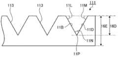
第一光扩散层111在其上面(一侧的面)具有凹凸结构,所述凹凸结构包含多个凹部113和位于凹部113的周围的平坦部114。利用该凹凸结构来限定光学片材100的表面10U。若忽略凹部113而宏观地看,表面10U为与平坦部114、透明基板121的光学片材中的其它层平行的平面,但微观上来看,其为包含由凹部113规定的斜面的凹凸面。另外,在本申请中,附图为示意性的图示,因此,在表面10U上仅表示有几个凹部,但在实际的装置中,在一个光学片材表面上,能够设置远比这几个凹部多的数量的凹部。The first light-diffusing
在本发明中,所谓“一侧”“另一侧”,是指识别光学片材的各层的表面侧的面及背面侧的面的限定,沿光学片材整体的厚度方向来规定,从透明基体材料观察时,第一光扩散层侧的方向为“一侧”,从透明基体材料观察时,第二光扩散层侧的方向为“另一侧”。In the present invention, the so-called "one side" and "the other side" refer to the definition of the surface on the front side and the back side of each layer of the optical sheet, and are defined along the thickness direction of the entire optical sheet. When viewed from the transparent base, the direction on the side of the first light-diffusing layer is "one side", and when viewed from the transparent base, the direction on the side of the second light-diffusing layer is "the other side".
例如,在本实施方式中,“一侧”相当于图2中的上侧,“另一侧”相当于图2中的下侧。即,在本实施方式中,透明基体材料121的“一侧的面”相当于透明基体材料121的上面,透明基体材料121的“另一侧的面”相当于透明基体材料121的下面。第一光扩散层111的“一侧的面”相当于第一光扩散层111的上面,第一光扩散层111的“另一侧的面”相当于第一光扩散层111的下面。For example, in the present embodiment, "one side" corresponds to the upper side in FIG. 2 , and "the other side" corresponds to the lower side in FIG. 2 . That is, in this embodiment, the “one side” of the
(透明基体材料)(transparent base material)
在本发明中,透明基体材料“透明”是指具有适合用于光学片材的材料的程度的光线透射率。在本发明中,构成光学片材的各层可以采用具有适合用于光学部件的光线透射率的材料,且可以采用光学片材整体上具有50%以上的总光线透射率的材料。In the present invention, the transparent base material "transparent" means having a light transmittance of a degree suitable for a material used in an optical sheet. In the present invention, each layer constituting the optical sheet can be made of a material having a light transmittance suitable for an optical component, and a material having a total light transmittance of 50% or more of the optical sheet as a whole can be used.
透明基体材料的材料没有特别限定,可以使用玻璃或者能够形成透明的层的各种树脂。作为透明基体材料的材料,例如能够举出:热塑性树脂、热固性树脂、紫外线固化性树脂、及电子束固化性树脂,其中,在易于加工方面,优选热塑性树脂。作为热塑性树脂,能够举出:聚酯类、聚丙烯酸酯类、及环烯烃聚合物类树脂。在此,作为透明基体材料,不限于单层的基体材料,也可以是将多个透明基体材料层叠形成的基体材料。The material of the transparent base material is not particularly limited, and glass or various resins capable of forming a transparent layer can be used. Examples of materials for the transparent substrate include thermoplastic resins, thermosetting resins, ultraviolet curable resins, and electron beam curable resins, among which thermoplastic resins are preferable in terms of ease of processing. Examples of thermoplastic resins include polyester-based, polyacrylate-based, and cycloolefin polymer-based resins. Here, the transparent base material is not limited to a single-layer base material, and may be a base material formed by laminating a plurality of transparent base materials.
在本发明的光学片材中,对于透明基体材料的厚度,例如,若由树脂构成,则优选为20~300μm。透明基体材料为玻璃时,其厚度优选为10~1100μm。需要说明的是,本发明的光学片材为薄的平板状结构,因此,称为“片材”,但挠性未必是必要条件。因此,例如采用700μm厚的玻璃作为透明基体材料制成的无挠性的层叠体的片材,也包含在本发明的光学片材内。In the optical sheet of the present invention, the thickness of the transparent base material is preferably 20 to 300 μm if it is made of a resin, for example. When the transparent base material is glass, its thickness is preferably 10 to 1100 μm. In addition, since the optical sheet of this invention is a thin flat plate structure, it is called a "sheet", but flexibility is not necessarily a requirement. Therefore, for example, an inflexible laminate sheet made of glass with a thickness of 700 μm as a transparent base material is also included in the optical sheet of the present invention.
(第一光扩散层)(first light diffusion layer)
第一光扩散层为设置于透明基体材料的第一面S1侧的层。在面光源装置设置有本发明的光学片材的情况下,通常,第一光扩散层设置于作为出光面侧(即,在光学片材中,与第二光扩散层及透明基体材料相比距离发光层更远的一侧)的面上。第一光扩散层也可以如图1及图2所示的光学片材100的第一光扩散层111的例子那样,直接设置于透明基体材料的面上,但也可以隔着其它的层来设置。从制造的容易度等观点出发,优选直接设置。The 1st light-diffusion layer is a layer provided in the 1st surface S1 side of a transparent base material. In the case where the surface light source device is provided with the optical sheet of the present invention, usually, the first light-diffusing layer is arranged on the side as the light-emitting surface (that is, in the optical sheet, compared with the second light-diffusing layer and the transparent base material on the side farther from the luminous layer). The first light-diffusing layer also can be directly arranged on the surface of the transparent base material like the example of the first light-diffusing
第一光扩散层的材料可以采用具有光扩散性的树脂组合物。具体而言,可以设定为包含各种树脂和光扩散粒子的组合物。作为所述树脂,例如,可以举出:热塑性树脂;热固性树脂;紫外线固化性树脂及电子束固化性树脂等能量线固化性树脂。其中,由于热塑性树脂容易因热而变形,另外,紫外线固化性树脂的固化性高、效率好,因此,可以高效地形成具有凹凸结构的光扩散层,从而均优选。作为热塑性树脂,能够举出聚酯类、聚丙烯酸酯类、及环烯烃聚合物类树脂。另外,作为紫外线固化性树脂,能够举出:环氧类树脂、丙烯酸类树脂、聚氨酯类树脂、硫醇和烯烃经反应而生成的树脂(エン/チオ一ル系)、异氰酸酯类树脂。作为这些树脂,可以优选使用具有多个聚合性官能团的树脂。The material of the first light-diffusing layer can be a resin composition having light-diffusing properties. Specifically, it can be set as a composition containing various resins and light-diffusing particles. Examples of the resin include thermoplastic resins; thermosetting resins; energy ray curable resins such as ultraviolet curable resins and electron beam curable resins. Among them, thermoplastic resins are easily deformed by heat, and ultraviolet curable resins are highly curable and efficient, and therefore can efficiently form a light-diffusing layer having a concavo-convex structure, and both are preferable. Examples of thermoplastic resins include polyester-based, polyacrylate-based, and cycloolefin polymer-based resins. In addition, examples of the ultraviolet curable resin include epoxy resins, acrylic resins, polyurethane resins, resins produced by the reaction of mercaptans and olefins (En/Chiol series), and isocyanate resins. As these resins, resins having a plurality of polymerizable functional groups can be preferably used.
第一光扩散层具有第一面D1及第二面D2,第一面D1是与上述透明基体材料相反侧的面。第二面D2为与上述透明基体材料的第一面S1对置的面。在本发明的某方式中,第一光扩散层的第一面D1为平滑面。在本发明的另一方式中,第一光扩散层的第一面D1上具有凹凸结构。The 1st light-diffusion layer has 1st surface D1 and 2nd surface D2, and 1st surface D1 is the surface opposite to the said transparent base material. The second surface D2 is a surface facing the first surface S1 of the above-mentioned transparent base material. In a certain aspect of this invention, the 1st surface D1 of a 1st light-diffusion layer is a smooth surface. In another aspect of this invention, the 1st light-diffusion layer has a concavo-convex structure on the 1st surface D1.
所谓第一面D1为平滑的面,是指算术平均粗糙度Ra<0.1um的面。另一方面,所谓第一面D1具有凹凸结构,是指Ra>0.15um的面。The term that the first surface D1 is smooth refers to a surface with an arithmetic average roughness Ra<0.1 μm. On the other hand, the term that the first surface D1 has a concavo-convex structure refers to a surface with Ra>0.15 um.
第一光扩散层在其第一面D1具有凹凸结构时,作为第一光扩散层的材料,从易形成凹凸结构且易获得凹凸结构的耐擦伤性的观点出发,优选固化后的硬度高的材料。具体而言,优选在基体材料上以无凹凸结构的状态形成7μm膜厚的层时,以铅笔硬度计硬度在HB以上的材料,进一步优选H以上的材料,更优选2H以上的材料。另一方面,作为透明基体材料的材料,为了容易进行形成第一光扩散层及第二光扩散层时的处理、和/或将光学片材成形后的处理,优选具有一定程度的柔软性。通过将这种材料组合,可以获得处理容易且耐久性优异的光学片材。这种材料的组合,可通过适当选用以上示例的树脂作为构成各自材料的树脂而获得。具体而言,作为构成第一光扩散层的材料的树脂,使用丙烯酸酯等紫外线固化性树脂,另一方面,作为构成透明基体材料的材料的树脂,可以使用脂环式烯烃聚合物制成的膜或聚酯膜,由此,可以获得优选的材料的组合。When the first light-diffusing layer has a concavo-convex structure on the first surface D1, the material of the first light-diffusing layer preferably has a high hardness after curing from the viewpoint of easily forming the concavo-convex structure and easily obtaining the scratch resistance of the concavo-convex structure. s material. Specifically, when a layer having a film thickness of 7 μm is formed on the base material without a concavo-convex structure, it is preferably a material with a pencil hardness of HB or higher, more preferably H or higher, and more preferably 2H or higher. On the other hand, the material of the transparent base material preferably has a certain degree of flexibility in order to facilitate handling when forming the first light-diffusing layer and the second light-diffusing layer and/or handling after molding the optical sheet. By combining such materials, an optical sheet that is easy to handle and excellent in durability can be obtained. Such a combination of materials can be obtained by appropriately selecting the resins exemplified above as the resins constituting the respective materials. Specifically, as the resin constituting the material of the first light-diffusing layer, an ultraviolet curable resin such as acrylate is used. On the other hand, as the resin constituting the material of the transparent base material, an alicyclic olefin polymer can be used. film or polyester film, whereby a preferred combination of materials can be obtained.
作为第一光扩散层可含有的光扩散粒子,能够举出各种粒子。该粒子可以透明,也可以不透明。作为粒子的材料,可以使用金属及金属化合物以及树脂等。作为金属化合物,可以举出金属的氧化物及氮化物。作为金属及金属化合物,具体而言,例如能够举出如银、铝那样反射率较高的金属、氧化硅、氧化铝、氧化锆、氮化硅、添加有锡的氧化铟、氧化钛等金属化合物。另一方面,作为树脂,能够举出甲基丙烯酸树脂、聚氨酯树脂、有机硅树脂等。Various particles can be mentioned as light-diffusion particle which a 1st light-diffusion layer can contain. The particle can be transparent or opaque. As the particle material, metals, metal compounds, resins, and the like can be used. Examples of the metal compound include metal oxides and nitrides. As metals and metal compounds, specifically, metals such as silver and aluminum with high reflectance, silicon oxide, aluminum oxide, zirconium oxide, silicon nitride, metals such as tin-added indium oxide, and titanium oxide can be mentioned. compound. On the other hand, examples of the resin include methacrylic resin, polyurethane resin, silicone resin, and the like.
粒子的形状可以为球状、圆柱状、立方体状、长方体状、棱锥状、圆锥状、星形状等形状。The shape of the particles may be spherical, cylindrical, cubic, cuboid, pyramidal, conical, star-like, and the like.
粒子的粒径优选在0.1μm以上10μm以下,更优选在5μm以下。在此,粒径是指以粒径为横轴对体积基准的粒子量累积计算得到的累积分布中的50%粒径。粒径越大,为了获得所期望的效果所需的粒子的含有比例越多,粒径越小,含量越少。因此,粒径越小,越能够用较少的粒子获得减少由于观察角度不同引起的色彩变化及提高光导出效率等所期望的效果。另外,关于粒径,在粒子的形状为球状以外的情况下,将其同等体积的球的直径作为粒径。The particle size of the particles is preferably not less than 0.1 μm and not more than 10 μm, more preferably not more than 5 μm. Here, the particle diameter refers to the 50% particle diameter in the cumulative distribution calculated by cumulatively calculating the amount of particles on a volume basis with the particle diameter as the abscissa. The larger the particle size, the larger the content ratio of particles required to obtain the desired effect, and the smaller the particle size, the less the content. Therefore, the smaller the particle size, the more desirable effects such as reducing color changes caused by different viewing angles and improving light extraction efficiency can be obtained with fewer particles. In addition, regarding the particle diameter, when the shape of the particle is other than spherical, the diameter of a sphere having the same volume is taken as the particle diameter.
在粒子为透明的粒子,且粒子被包含在透明树脂中的情况下,粒子的折射率和透明树脂的折射率之差,优选0.05~0.5,更优选0.07~0.5。在此,粒子及透明树脂的折射率,哪个更大都可以。粒子和透明树脂的折射率过于接近时,不能获得扩散效果,不能抑制色彩不均,相反,粒子和透明树脂的折射率之差过大时,则扩散变大,虽然抑制了色彩不均,但光导出效果会降低。When the particles are transparent and the particles are contained in a transparent resin, the difference between the refractive index of the particles and the refractive index of the transparent resin is preferably 0.05 to 0.5, more preferably 0.07 to 0.5. Here, the particles and the transparent resin may have a larger refractive index. If the refractive index of the particles and the transparent resin are too close, the diffusion effect cannot be obtained, and the color unevenness cannot be suppressed. Conversely, if the difference between the refractive index of the particles and the transparent resin is too large, the diffusion will become larger, and the color unevenness will be suppressed. The light export effect will be reduced.
第一光扩散层包含树脂和光扩散粒子的情况下,树脂和光扩散粒子的配合比例优选3~50重量%。When the first light-diffusing layer contains resin and light-diffusing particles, the compounding ratio of the resin and the light-diffusing particles is preferably 3 to 50% by weight.
在本发明的光学片材中,就第一光扩散层的厚度而言,其下限优选在1μm以上,更优选在5μm以上,另外,可以采用10μm以上,另一方面,其上限优选50μm以下,更优选25μm以下,另外,可以采用15μm以下。特别地,通过采用上述上限以下的厚度,可以防止固化收缩带来的光学片材的翘曲等变形,从而形成良好的形状的光学片材。In the optical sheet of the present invention, the lower limit of the thickness of the first light-diffusing layer is preferably 1 μm or more, more preferably 5 μm or more, and may be 10 μm or more. On the other hand, the upper limit is preferably 50 μm or less, It is more preferably 25 μm or less, and 15 μm or less can be used. In particular, by adopting the thickness below the above-mentioned upper limit, deformation such as warping of the optical sheet due to curing shrinkage can be prevented, and an optical sheet with a favorable shape can be formed.
上面作为第一光扩散层的材料所举出的固化后硬度较高的树脂,有容易产生固化收缩的倾向。因此,一般在采用这种材料作为光学片材的一部分的层材料时,容易使厚度变得不均匀,发生光学片材变形(卷曲等)等不良情况。特别地,为了对光学片材赋予充分的扩散性能而在第一光扩散层中配合光扩散粒子且增厚其厚度时,容易产生这种固化收缩引起的变形。但是,在本发明的光学片材中,作为第一光扩散层及第二光扩散层,采用后述的具有规定雾度比的材料,由此,即使第一光扩散层的厚度很薄,也能够形成具有规定的扩散性能的光学片材。其结果是,本发明的光学片材能够成为满足如下的全部内容的光学片材,即,表面耐久性高、由均匀的厚度产生的面内透射率的均匀度高、由充分的光扩散性能产生的由观察角度不同引起的色彩变化少、及变形小。The resins with high hardness after curing mentioned above as the material of the first light-diffusing layer tend to easily cause curing shrinkage. Therefore, in general, when such a material is used as a layer material of a part of an optical sheet, the thickness tends to become non-uniform, and defects such as deformation (curling, etc.) of the optical sheet tend to occur. In particular, when light-diffusing particles are added to the first light-diffusing layer to increase the thickness in order to impart sufficient diffusing performance to the optical sheet, such deformation due to cure shrinkage tends to occur. However, in the optical sheet of the present invention, as the first light-diffusing layer and the second light-diffusing layer, a material having a predetermined haze ratio described later is used, so that even if the thickness of the first light-diffusing layer is very thin, It is also possible to form an optical sheet having predetermined diffusion performance. As a result, the optical sheet of the present invention can be an optical sheet that satisfies all of the following, that is, high surface durability, high uniformity of in-plane transmittance due to uniform thickness, and sufficient light diffusing performance. The color change and deformation caused by different viewing angles are small.
(第二光扩散层)(second light diffusion layer)
第二光扩散层设置于透明基体材料的第二面S2侧,即透明基体材料的与设置有第一光扩散层的面相反的面侧。在本发明的光学片材被设置于面光源装置上的情况下,第二光扩散层通常为设置于入光面侧(即比第一光扩散层及透明基体材料更靠近发光层的一侧)的层。如图1及图2所示的光学片材100中的第二光扩散层112的例子那样,第二光扩散层可以直接设置于透明基体材料的面上,还可以经由其它的层设置在透明基体材料面上。从制造的容易度等观点出发,优选直接设置。The 2nd light-diffusion layer is provided in the 2nd surface S2 side of a transparent base material, ie, the surface side opposite to the surface provided with the 1st light-diffusion layer of a transparent base material. When the optical sheet of the present invention is placed on a surface light source device, the second light-diffusing layer is usually placed on the light-incident side (that is, on the side closer to the light-emitting layer than the first light-diffusing layer and the transparent base material). ) layers. Like the example of the second light-diffusing
第二光扩散层可以设定为具有光扩散性的层,但特别优选具有光扩散性的粘合层。即,第二光扩散层可以采用不仅具有使透过光学片材的光发生扩散的功能,还具有使光学片材粘合在有机EL元件其它层上的功能的层。通过将第二光扩散层设定为粘合层,能够容易地将本发明的光学片材设置于有机EL元件上,且简化有机EL元件的层结构,从而能够提高光导出效率。另外,从提高有机EL元件的光导出效率的观点出发,优选第二光扩散层的折射率比第一光扩散层的折射率高。该情况下,通过将不具有粘合性的层作为第二扩散层,并使用能量线固化性树脂、热固化性树脂等,能够制成折射率高达1.6以上,进一步优选1.67以上的层。作为能量线固化性树脂的例子,可以举出紫外线固化性树脂及电子束固化性树脂。The second light-diffusing layer may be a layer having light-diffusing properties, but an adhesive layer having light-diffusing properties is particularly preferable. That is, as the second light-diffusing layer, a layer having not only a function of diffusing light transmitted through the optical sheet but also a function of bonding the optical sheet to other layers of the organic EL element can be used. By setting the second light-diffusing layer as an adhesive layer, the optical sheet of the present invention can be easily provided on the organic EL element, and the layer structure of the organic EL element can be simplified to improve light extraction efficiency. Moreover, from a viewpoint of improving the light extraction efficiency of an organic EL element, it is preferable that the refractive index of a 2nd light-diffusion layer is higher than the refractive index of a 1st light-diffusion layer. In this case, by using a non-adhesive layer as the second diffusion layer and using an energy ray-curable resin, a thermosetting resin, or the like, a layer having a high refractive index of 1.6 or more, more preferably 1.67 or more can be obtained. Examples of energy ray curable resins include ultraviolet curable resins and electron beam curable resins.
第二光扩散层的材料可以设定为具有光扩散性的任意的材料。作为具有第二光扩散层的材料的一个例子,可以举出树脂和光扩散粒子的组合物。该情况下,作为该树脂,例如可以使用环氧树脂、(甲基)丙烯酸树脂、有机硅树脂、聚氨酯树脂、聚酰亚胺树脂、酸改性聚烯烃树脂或其混合物等。通过使用这些树脂,可以容易地形成第二光扩散层,且还能够对第二光扩散层赋予作为上述粘合层的功能。另一方面,作为光扩散粒子,可以使用与第一光扩散层的光扩散粒子同样的材料。第二光扩散层包含树脂和光扩散粒子的情况下,树脂和光扩散粒子的添加比例优选3~50重量%。The material of the second light-diffusing layer can be set to any material having light-diffusing properties. As an example of the material which has a 2nd light-diffusion layer, the composition of resin and light-diffusion particle|grains is mentioned. In this case, as the resin, for example, epoxy resin, (meth)acrylic resin, silicone resin, polyurethane resin, polyimide resin, acid-modified polyolefin resin or a mixture thereof can be used. By using these resins, the 2nd light-diffusion layer can be formed easily, and the function as the said adhesive layer can also be given to a 2nd light-diffusion layer. On the other hand, as the light-diffusing particles, the same material as that of the light-diffusing particles in the first light-diffusing layer can be used. When the second light-diffusing layer contains resin and light-diffusing particles, the addition ratio of the resin and the light-diffusing particles is preferably 3 to 50% by weight.
作为第二光扩散层的材料的其它的例子,可以举出发生了无规取向的液晶性物质的层、或使该液晶性物质的层在维持这种取向的状态下直接固化得到的固化液晶性物质的层。当使光进入这种发生了无规取向的层内时,光的行进方向会发生各种变化,因此,可以实现扩散。发生了无规取向的液晶性物质的层不限于固体的层,例如也可以是填充于合适的间隙中的液体的层。Other examples of the material of the second light-diffusing layer include a layer of a liquid crystalline material in which random orientation has occurred, or a cured liquid crystal obtained by directly curing the layer of the liquid crystalline material while maintaining this orientation. layer of sexual substance. When light enters such a randomly oriented layer, the traveling direction of the light changes in various ways, so that diffusion can be realized. The layer of the randomly oriented liquid crystal material is not limited to a solid layer, and may be, for example, a liquid layer filled in appropriate gaps.
使用液晶性物质作为第二光扩散层时,作为这种液晶性物质,可举出各种近晶态液晶、向列液晶、液晶性丙烯酸酯及其混合物等。When using a liquid crystalline substance as a 2nd light-diffusion layer, as such a liquid crystalline substance, various smectic liquid crystals, nematic liquid crystals, liquid crystalline acrylates, mixtures thereof, etc. are mentioned.
就本发明的光学片材而言,优选第二光扩散层的厚度下限为1μm以上,更优选10μm以上,进而可以设定为30μm以上或40μm以上,另一方面,优选其上限在200μm以下,更优选在60μm以下。For the optical sheet of the present invention, the lower limit of the thickness of the second light-diffusing layer is preferably 1 μm or more, more preferably 10 μm or more, and can be set to 30 μm or more or 40 μm or more. On the other hand, the upper limit is preferably 200 μm or less. More preferably, it is 60 μm or less.
(雾度的关系)(relationship of haze)
在本发明的光学片材中,上述第一光扩散层的雾度x1(%)和上述第二光扩散层的雾度x2(%),满足下述式(1)。In the optical sheet of the present invention, the haze x1 (%) of the first light-diffusing layer and the haze x2 (%) of the second light-diffusing layer satisfy the following formula (1).
f(x1)/(f(x1)+f(x2))≤2/3…式(1)f(x1)/(f(x1)+f(x2))≤2/3...Formula (1)
其中,就函数f(x)而言,在x≤88时,函数f(x)=1.9×(ln(1-x/90))2,在x>88时,函数f(x)=22.5x-1952.5。Among them, as far as the function f(x) is concerned, when x≤88, the function f(x)=1.9×(ln(1-x/90))2 , and when x>88, the function f(x)=22.5 x-1952.5.
雾度x1及雾度x2更优选的是满足下述式(1’)。The haze x1 and haze x2 more preferably satisfy the following formula (1').
f(x1)/(f(x1)+f(x2))≤1/2…式(1’)f(x1)/(f(x1)+f(x2))≤1/2...Formula (1')
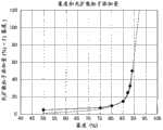
这种函数f(x)是如下导出的函数:改变添加于固化后折射率达到1.54的UV固化性树脂中的平均粒径为2μm且折射率为1.43的光扩散粒子的比例,并在基体材料膜上形成膜厚15μm的平坦光扩散层,由此时的雾度和光扩散粒子添加比例导出。图9表示该关系。图中实线为实测结果,虚线相当于f(x)的值。在本申请中,将相当于上述添加比例的值作为表示散射性能的指标,将两个光散射层的散射性能进行比较,规定了式(1)及式(2)的范围。Such a function f(x) is a function derived by changing the ratio of light-diffusing particles with an average particle diameter of 2 μm and a refractive index of 1.43 added to a UV curable resin whose cured refractive index is 1.54, and adding it to the base material A flat light-diffusing layer with a film thickness of 15 μm was formed on the film, and it was derived from the haze at that time and the addition ratio of light-diffusing particles. Fig. 9 shows this relationship. The solid line in the figure is the actual measurement result, and the dotted line corresponds to the value of f(x). In the present application, a value corresponding to the above-mentioned addition ratio is used as an index showing the scattering performance, and the scattering performance of two light scattering layers is compared, and the ranges of the formulas (1) and (2) are defined.
进而,本发明的光学片材优选Furthermore, the optical sheet of the present invention is preferably
f(x1)+f(x2)≥12…式(2)。f(x1)+f(x2)≥12...Formula (2).
换言之,优选的是具有在上述的15μm的光扩散层中光扩散粒子的添加量多于12重量%时的散射性能。进而,本发明的光学片材优选In other words, it is preferable to have the scattering performance when the added amount of the light-diffusing particles exceeds 12% by weight in the above-mentioned 15 μm light-diffusing layer. Furthermore, the optical sheet of the present invention is preferably
f(x1)+f(x2)≥18…式(2’)。f(x1)+f(x2)≥18...Formula (2').
第一光扩散层的第一面D1为平滑面时,雾度x1为第一光扩散层的雾度。另一方面,第一光扩散层在其第一面D1具有凹凸结构时,雾度x1不是第一光扩散层本身的雾度,而是与第一光扩散层具有相同材料及相同厚度但不具有第一光扩散层中的凹凸结构的其它光扩散层的雾度。When the 1st surface D1 of a 1st light-diffusion layer is a smooth surface, haze x1 is the haze of a 1st light-diffusion layer. On the other hand, when the first light-diffusing layer has a concavo-convex structure on its first surface D1, the haze x1 is not the haze of the first light-diffusing layer itself, but has the same material and the same thickness as the first light-diffusing layer but not Haze of other light-diffusing layers having the concavo-convex structure in the first light-diffusing layer.
可以通过在透明的基板上形成作为测定对象的第一光扩散层或第二光扩散层,并测定其雾度来可测定雾度x1及雾度x2。另外,对于表面具有凹凸结构的第一光扩散层,形成与其具有相同材料及相同平均厚度的平坦层,测定其雾度并作为x1。或者,对于已经形成有凹凸结构的第一光扩散层,用与第一光扩散层折射率相同的透明树脂,填埋上述的凹凸结构,进行平坦化,测定雾度并作为x1。作为测量设备,可以根据JIS K7105使用市售的浊度仪(NDH-300A日本电色工业社制等)。The haze x1 and the haze x2 can be measured by forming the first light-diffusing layer or the second light-diffusing layer to be measured on a transparent substrate and measuring the haze. Moreover, the 1st light-diffusion layer which has an uneven|corrugated structure on the surface formed the flat layer which has the same material and the same average thickness as that, and measured the haze and made it x1. Alternatively, for the first light-diffusing layer already formed with the concave-convex structure, the above-mentioned concave-convex structure is filled with a transparent resin having the same refractive index as the first light-diffusing layer, planarized, and the haze is measured as x1. As a measuring device, a commercially available turbidimeter (NDH-300A manufactured by Nippon Denshoku Kogyo Co., Ltd., etc.) can be used in accordance with JIS K7105.
雾度x1及雾度x2除满足上述式(1)之外,还满足上述式(2),从而能够满足以下所有要求,即,光学片材具有均匀的面内透射率、透射光的观察角度不同引起的色彩变化较低、光学片材表面的机械强度较高。Haze x1 and haze x2 satisfy the above-mentioned formula (2) in addition to the above-mentioned formula (1), so that all of the following requirements can be satisfied, that is, the optical sheet has a uniform in-plane transmittance, an observation angle of transmitted light The color change caused by the difference is low, and the mechanical strength of the surface of the optical sheet is high.
即,为了提高光学片材表面的机械强度,需要提高光扩散层的硬度,在为了提高光导出效率而在光学片材表面设置凹凸结构的情况下,这一点的必要性进一步突显。进而,为了抑制观察角度不同引起的色彩变化,需要提高光学片材的雾度,要求向光扩散层添加大量的光扩散粒子。但是,当使用硬度较高的材料,且较多地添加光扩散层时,则固化前的材料的粘度升高,因此,难以提高层的成形精度,而且,厚度的轻微的不均匀就会显现出很大的透射率变化,结果,难以获得均匀的面内透射率。于是,在本发明中,设置用于提高硬度的第一光扩散层和用于提高扩散性的第二扩散层,进而,通过将这些雾度的比设定在上述规定范围,能够达到上述效果。That is, in order to increase the mechanical strength of the surface of the optical sheet, it is necessary to increase the hardness of the light-diffusing layer, and the need for this becomes more pronounced when a concavo-convex structure is provided on the surface of the optical sheet to improve light extraction efficiency. Furthermore, in order to suppress the color change by different viewing angles, it is necessary to increase the haze of an optical sheet, and it is required to add a large amount of light-diffusion particles to a light-diffusion layer. However, when a material with high hardness is used and a large amount of light-diffusing layer is added, the viscosity of the material before curing increases, so it is difficult to improve the forming accuracy of the layer, and slight unevenness in thickness appears. A large change in transmittance occurs, and as a result, it is difficult to obtain uniform in-plane transmittance. Therefore, in the present invention, the first light-diffusing layer for increasing the hardness and the second diffusing layer for increasing the diffusivity are provided, and the above-mentioned effect can be achieved by setting the ratio of these hazes within the above-mentioned predetermined range. .
雾度x1及雾度x2各自的值没有特别地限定,只要满足上述必要条件即可,但x1的下限优选50%,更优选75%,x1的上限优选90%,更优选89.5%。特别地,x1的下限在上述优选的范围以上时,在第一光扩散层的表面上产生了微小的损伤的情况下,也能够良好地缓解这种损伤引起的光学片材的性能降低(例如面内透射率的均匀性降低等),因此特别优选。x2的下限优选75%,更优选85%,x2的上限优选90%,更优选89.5%。The respective values of haze x1 and haze x2 are not particularly limited as long as the above-mentioned necessary conditions are met, but the lower limit of x1 is preferably 50%, more preferably 75%, and the upper limit of x1 is preferably 90%, more preferably 89.5%. In particular, when the lower limit of x1 is more than the above-mentioned preferred range, even when minute damage occurs on the surface of the first light-diffusing layer, the degradation in performance of the optical sheet due to such damage (such as Uniformity of in-plane transmittance decreases, etc.), so it is particularly preferable. The lower limit of x2 is preferably 75%, more preferably 85%, and the upper limit of x2 is preferably 90%, more preferably 89.5%.
(凹凸结构)(concave-convex structure)
在本发明的光学片材中,优选的是第一光扩散层在其第一面D1(表侧的面)上具有凹凸结构。在此所说的第一光扩散层的“表侧的面”是指第一光扩散层的与透明基体材料侧的面相反侧的面。作为该凹凸结构,可以优选举出包含具有斜面的多个凹部和位于上述凹部的周围的平坦部的凹凸结构。在此“斜面”是指,呈现与透明基体材料的面方向不平行的角度的面。另一方面,平坦部上的面可以设定为与透明基体材料的面方向平行的面。In the optical sheet of the present invention, it is preferable that the first light-diffusing layer has an uneven structure on the first surface D1 (surface on the front side). The "front side surface" of the 1st light-diffusion layer mentioned here means the surface of the 1st light-diffusion layer opposite to the surface by the transparent base material side. As the concavo-convex structure, a concavo-convex structure including a plurality of concave portions having inclined surfaces and a flat portion positioned around the concave portions is preferably used. Here, the "inclined surface" refers to a surface that presents an angle that is not parallel to the surface direction of the transparent base material. On the other hand, the surface on the flat portion may be set to be a surface parallel to the surface direction of the transparent base material.
作为凹凸结构的例子,参照图3及图4更详细地对图1及图2所示的光学片材100的第一光扩散层111的上面的凹凸结构进行说明。图3是示意性地表示将由第一光扩散层111的表面结构所规定的光学片材100的表面10U的结构进行放大后的局部俯视图。图4是表示用通过图3的线10a并与第一扩散层111垂直的面将第一扩散层111切断后的截面的局部剖面图。As an example of the concave-convex structure, the concave-convex structure on the upper surface of the first light-diffusing
多个凹部113分别为正四棱锥形状的凹陷,因此,凹部113的斜面11A~11D为相同的形状,底边11E~11H构成正方形。线10a为通过一列凹部113的全部顶点11P的上方的线,且该线是与凹部113的底边11E及11G平行的线。The plurality of
凹部113隔开一定的间隔沿垂直的两个设置方向连续设置。这种两个设置方向中一方向X与底边11E及11G平行。在该方向X上,多个凹部113隔开一定的间隔11J排列。两个设置方向中另一方向Y与11F及11H平行。在该方向Y上,多个凹部113隔开一定的间隔11K排列。The
构成各个凹部113的斜面11A~11D与平坦部114所成的角(对于斜面11B及11D而言,分别为图4所示的角11L及11M)例如设定为60°,由此,对于构成凹部113的正四棱锥的顶角,即在顶点11P上相对向的斜面所成的角(对于斜面11B及11D所成的角,为图4所示的角11N)也设定为60°。The angles formed by the
这样,光学片材具有如下结构:即,在相当于面光源装置的装置出光面的第一扩散层侧表面上,包含多个凹部和位于各凹部的周围的平坦部,进而,光学片材具有光扩散性,从而能够提高光导出效率,且能够降低观察角度不同引起的色彩变化,而且,能够防止因外部冲击而产生凹凸结构的缺陷等,进而能够提高装置出光面的机械强度。In this way, the optical sheet has the following structure: that is, on the first diffusion layer side surface corresponding to the device light-emitting surface of the surface light source device, it includes a plurality of concave parts and a flat part positioned around each concave part, and furthermore, the optical sheet has Light diffusivity can improve light export efficiency, reduce color changes caused by different viewing angles, and prevent defects in the concave-convex structure caused by external impacts, thereby improving the mechanical strength of the light-emitting surface of the device.
本发明的光学片材由于具有上述的凹凸结构,从而与不采用上述构成的情况相比,能够进一步降低从第一光扩散层侧导出的光在半球状全方位的色度坐标中x坐标及y坐标中至少任一个的位移。因此,在具备本发明的光学片材的本发明的面光源装置中,能够进一步抑制观察角度不同造成的色彩变化。作为测定这种半球状全方位的色度的位移的方法,例如,在装置出光面的法线方向(即,忽略凹部而宏观地看到的与装置出光面垂直的方向)上设置分光辐射亮度计,安装将法线方向设定为0°时能够使该装置出光面在-90~90°范围进行旋转的机构,从而,可以从在各方向测定的发光光谱计算色度坐标,因此,可算出其位移。Since the optical sheet of the present invention has the above-mentioned concavo-convex structure, compared with the case where the above-mentioned structure is not adopted, the x-coordinate and x-coordinate of the light derived from the first light-diffusing layer side in the hemispherical omnidirectional chromaticity coordinates can be further reduced. The displacement of at least one of the y coordinates. Therefore, in the surface light source device of the present invention provided with the optical sheet of the present invention, it is possible to further suppress color changes due to differences in viewing angles. As a method of measuring the displacement of such hemispherical omnidirectional chromaticity, for example, the spectral radiance is set on the normal direction of the light-emitting surface of the device (that is, the direction perpendicular to the light-emitting surface of the device macroscopically ignoring the concave portion) When the normal direction is set to 0°, a mechanism that can make the light-emitting surface of the device rotate in the range of -90 to 90° is installed, so that the chromaticity coordinates can be calculated from the luminescence spectrum measured in each direction, therefore, it is possible to Calculate its displacement.
通过适当调节“平坦部比例”,可以提高面光源装置的光导出效率,所述“平坦部比例”是指,从与光学片材垂直的方向观察凹凸结构时,平坦部所占的面积相对于平坦部所占的面积和凹部所占的面积的总和的比例。具体而言,通过将平坦部比例设定为10~75%,可以获得良好的光导出效率,且能够提高装置出光面的机械强度。The light extraction efficiency of the surface light source device can be improved by properly adjusting the "flat portion ratio", which refers to the area occupied by the flat portion relative to the concave-convex structure when viewed from a direction perpendicular to the optical sheet The ratio of the area occupied by the flat portion to the sum of the area occupied by the concave portion. Specifically, by setting the proportion of the flat portion at 10% to 75%, good light extraction efficiency can be obtained, and the mechanical strength of the light output surface of the device can be improved.
第一光扩散层在其表面上具有凹凸结构的情况下,就凹部而言,例如,不仅可以具有上面所述的棱锥形状,还可具有圆锥形状、球面的一部分的形状、沟状的形状及将它们组合的形状。棱锥形状可以采用上述作为凹部113所列举的底面为正方形的四棱锥,但不限于此,也可以设定为三棱锥、五棱锥、六棱锥、底面不是正方形的四棱锥等棱锥形状。When the first light-diffusing layer has a concave-convex structure on its surface, for example, the concave portion may have not only the above-mentioned pyramid shape, but also a conical shape, a part of a spherical shape, a groove-like shape, and A shape combining them. The shape of the pyramid can be a quadrangular pyramid whose base is a square as mentioned above as the
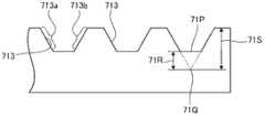
另外,本申请中所说的圆锥及棱锥,不仅包含其顶部尖锐的普通圆锥及棱锥,还包含前端带圆角的形状、或平坦倒角的形状(圆台或者棱台状的形状等)。例如,在图4所示的凹部113中,四棱锥的顶部11P为尖锐形状,但其也可以为如图5所示的凹部613的顶部61P那样带有圆角的形状。另外,也可以如图6所示的凹部71那样,在棱锥的顶部设置平坦的部分71P,成为被平坦倒角的形状。In addition, the cones and pyramids mentioned in this application include not only ordinary cones and pyramids with sharp tops, but also shapes with rounded corners or flat chamfered corners (such as truncated cones or truncated pyramids). For example, in the
如图5所示,在棱锥的顶部为带圆角的形状时,其顶部61P与该棱锥不带圆角而是尖锐形状时的顶部61Q之间的高度差61R,可以设定为该棱锥不带圆角而是尖锐形状时的棱锥的高度61S的20%以下。如图6所示,棱锥的顶部为平坦倒角的形状时,平坦的部分71P与该棱锥的顶部不是平坦而是尖锐形状时的顶部71Q之间的高度差71R,可以设定为该棱锥的顶部不是平坦而是尖锐形状时的棱锥的高度71S的20%以下。As shown in Figure 5, when the top of the pyramid is a shape with rounded corners, the height difference 61R between its top 61P and the top 61Q when the pyramid does not have rounded corners but a sharp shape can be set so that the pyramid does not have rounded corners. The height of the pyramid with a rounded but sharp shape is 20% or less of 61S. As shown in Figure 6, when the top of the pyramid is a flat chamfered shape, the
凹凸结构中的凹部的深度没有特别限定,但就沿着各个方向(与出光面平行的面内的各个方向)对形成有凹凸结构的表面进行测定得到的中心线平均粗糙度最大值(Ra(max))而言,可以设定在1~50μm的范围内。在第一光扩散层上形成凹凸结构的情况下,可以对于第一光扩散层的厚度,相对地决定优选的凹部深度。例如,在使用有利于维持第一光扩散层的耐久性的硬质材料作为第一光扩散层的材料时,使凹凸结构层的厚度变薄可以提高光学片材的挠性,且面光源装置的制造工序中光学片材的处理变得容易。具体而言,第一光扩散层111的厚度16E相对于图4所示的凹部的深度16D的比例,优选16D:16E=1:1~1:3。The depth of the concave portion in the concave-convex structure is not particularly limited, but the centerline average roughness maximum value (Ra( max)) can be set within the range of 1 to 50 μm. When forming the concavo-convex structure on the first light-diffusing layer, it is possible to relatively determine a preferable depth of the concave portion with respect to the thickness of the first light-diffusing layer. For example, when using a hard material that is conducive to maintaining the durability of the first light-diffusing layer as the material of the first light-diffusing layer, making the thickness of the concave-convex structure layer thinner can improve the flexibility of the optical sheet, and the surface light source device The handling of the optical sheet becomes easy in the manufacturing process. Specifically, the ratio of the
在本发明中,凹部的斜面与出光面所成的角优选40~70°,更优选45~60°。例如在凹部的形状为图4、11及12所示的四棱锥的情况下,其顶角(图4中的角11P)优选为60~90°。另外,从将观察角度不同造成的色彩变化控制在最小限度,同时提高光导出效率的观点出发,优选斜面与透明基体材料的面所成的角较大为好,具体而言,例如优选设定为55°以上,更加优选设定在60°以上。该情况下,若考虑维持第一光扩散层的耐久性,这种角的上限可以为70°左右。In the present invention, the angle formed by the slope of the concave portion and the light-emitting surface is preferably 40-70°, more preferably 45-60°. For example, when the shape of the concave portion is a quadrangular pyramid as shown in FIGS. 4 , 11 and 12 , the apex angle (
凹部的形状为顶部带圆角的形状或者具有平坦倒角的棱锥形状、圆锥形状或者沟状的形状时,将除了该带圆角的部分或者倒角的部分以外的斜面的角度,作为斜面的角度。例如,在图5及图6所示的例子中,将面613a、613b、713a及713b作为棱锥的斜面。通过将斜面的角度设定为这种角度,能够提高光导出效率。凹凸结构的斜面未必全部为相同的角度,也可以在上述范围内具有不同的角度的斜面共存。另外,圆锥形状的斜面和透明基体材料的面所成的角,可以采用这种圆锥的母线和透明基体材料的面所成的角。When the shape of the recess is a shape with a rounded top or a pyramid shape with a flat chamfer, a cone shape, or a groove shape, the angle of the slope other than the rounded portion or the chamfered portion is taken as the angle of the slope. angle. For example, in the example shown in FIG. 5 and FIG. 6, the
在第一光扩散层的表面,多个凹部能够以任意形态排列。例如,可以将多个凹部沿表面上的两个以上的方向进行排列。更具体而言,如图1及图3所示的凹部113那样,可以沿垂直的两个方向进行排列。On the surface of the first light-diffusing layer, a plurality of recesses can be arranged in any form. For example, a plurality of recesses may be arranged in two or more directions on the surface. More specifically, like the
在两个以上的方向排列有凹部的情况下,可以在它们中一个方向以上的方向上,设置相邻的凹部间的间隙,利用这种间隙构成平坦部。例如,在图3所示的凹部113的排列中,在垂直的两个方向上,分别设置间隔11J及11K的间隙,利用这种间隙构成平坦部114。通过采用这种构成,能够兼顾良好的光导出效率和片材表面的机械强度。When recesses are arranged in two or more directions, gaps between adjacent recesses may be provided in one or more directions among them, and the flat portion may be formed by using such gaps. For example, in the arrangement of the
(制造方法)(Manufacturing method)
本发明的光学片材例如可以通过以下方法进行制造,即,制备适于形成第一光扩散层的树脂组合物(1)及适于形成第二光扩散层的涂敷液(2),使用它们在透明基体材料的两面上分别形成第一光扩散层及第二光扩散层。The optical sheet of the present invention can be produced, for example, by preparing a resin composition (1) suitable for forming a first light-diffusing layer and a coating solution (2) suitable for forming a second light-diffusing layer, using They respectively form a first light-diffusing layer and a second light-diffusing layer on both sides of the transparent base material.
(第一光扩散层的形成方法)(Method for forming first light-diffusing layer)
作为适于形成第一光扩散层的树脂组合物(1),可以使用包含上述列举的光扩散层的材料的树脂,即固化前的树脂和扩散剂的组合物。树脂组合物(1),根据需要可以包含溶剂。但是,从能够顺利地进行后述的光敏聚合物法等观点出发,树脂组合物(1)优选采用在制备时不添加溶剂,而形成工序中很少存在或不存在必须挥发的成分的组合物。As a resin composition (1) suitable for forming a 1st light-diffusion layer, resin containing the material of the light-diffusion layer mentioned above, ie, the composition of the resin before hardening, and a diffusing agent can be used. The resin composition (1) may contain a solvent as needed. However, the resin composition (1) is preferably a composition in which no solvent is added at the time of preparation, and there are few or no components that must be volatilized in the forming process, from the viewpoint that the photopolymer method described later can be carried out smoothly. .
另一方面,这种制备时不添加溶剂的树脂组合物(1),存在涂布获得的涂膜的厚度不均增大的倾向。因此,一般地,采用这种材料作为光学片材的一部分层的材料时,容易产生厚度变得不均匀、面内的透射率的均匀度降低等不良情况。但是,在本发明的光学片材中,作为第一光扩散层及第二光扩散层,通过采用具有后述的规定雾度比的材料,即使第一光扩散层的扩散性低,也能够制成具有规定的扩散性能的光学片材,其结果,可以制成具有各种良好的特性,且通过光敏聚合物法即可容易地制造的光学片材。On the other hand, such a resin composition (1) prepared without adding a solvent tends to increase the thickness unevenness of the coating film obtained by coating. Therefore, in general, when such a material is used as a material for a part of an optical sheet, problems such as non-uniformity in thickness and decrease in uniformity of in-plane transmittance tend to occur. However, in the optical sheet of the present invention, by using a material having a predetermined haze ratio described later as the first light-diffusing layer and the second light-diffusing layer, even if the diffusivity of the first light-diffusing layer is low, it is possible to An optical sheet having a predetermined diffusion performance can be obtained, and as a result, an optical sheet having various favorable characteristics and which can be easily produced by a photopolymer method can be obtained.
将树脂组合物(1)涂布在透明基体材料的面上而获得涂膜,视需要,使涂膜中的溶剂挥发,进而,根据需要,通过能量线的照射等来进行固化处理,由此可以获得第一光扩散层。The resin composition (1) is coated on the surface of a transparent base material to obtain a coating film, and if necessary, the solvent in the coating film is volatilized, and further, if necessary, curing treatment is performed by irradiation of energy rays, etc., thereby A first light diffusing layer can be obtained.
第一光扩散层在其表面具有凹凸时,这种凹凸结构的形成可以通过以下方法形成:制备具有所期望的形状的模具等模型,在获得上述涂膜后的任意阶段转印上述模具的形状。When the first light-diffusing layer has unevenness on its surface, the formation of such an uneven structure can be formed by preparing a model such as a mold having a desired shape, and transferring the shape of the above-mentioned mold at any stage after the above-mentioned coating film is obtained. .
更具体而言,优选在获得上述涂膜后进行固化处理之前,通过光敏聚合物法形成凹凸结构。即,优选的是,将模具按压在形成的上述涂膜上,在该状态下使涂膜固化,形成具有凹凸结构并已固化的层。该情况下,作为树脂组合物(1),优选使用可利用紫外线等能量线进行固化的组合物。将这种树脂组合物(1)涂布在透明基体材料上而获得涂膜,在将模具按压在该涂膜上的状态下,从位于涂布面的背面(透明基体材料的与涂布有树脂组合物(1)的面相反的一侧)的光源照射紫外线等能量线,使树脂组合物(1)固化,然后,将模具剥离,由此可以获得具有模具的凹凸结构倒置而成的形状的凹凸结构的第一光扩散层。More specifically, it is preferable to form a concavo-convex structure by a photopolymer method before performing a curing treatment after obtaining the above coating film. That is, it is preferable to press a mold on the formed coating film, and to cure the coating film in this state to form a cured layer having a concavo-convex structure. In this case, as the resin composition (1), it is preferable to use a composition curable by energy rays such as ultraviolet rays. This resin composition (1) was coated on a transparent base material to obtain a coating film, and in a state where the mold was pressed against the coating film, the The resin composition (1) is irradiated with energy rays such as ultraviolet rays from a light source opposite to the surface of the resin composition (1) to cure the resin composition (1), and then the mold is peeled off to obtain a shape in which the concave-convex structure of the mold is reversed. The first light-diffusing layer of the concavo-convex structure.
(第二光扩散层的形成方法)(Method for forming second light-diffusing layer)
作为适于形成第二光扩散层的涂敷液(2),可以使用包含上述列举的光扩散层的材料的树脂即固化前的树脂和扩散剂的组合物。涂敷液(2)优选进一步包含溶剂。作为上述溶剂,可以列举甲苯、己烷、环己烷、甲乙酮、乙酸乙酯等。通过将涂敷液(2)制成包含上述溶剂的组合物,即使该组合物扩散性较高,也可以以均匀的厚度制造第二光扩散层。其结果,可以容易地获得下述光学片材,该光学片材兼备由透射光的观察角度不同造成的色彩变化较少、以及面内的透射率均匀。在涂敷液(2)包含树脂、光扩散粒子及溶剂的情况下,涂敷液(2)整体中的溶剂的比例,可以采用50~95重量%。As a coating liquid (2) suitable for forming a 2nd light-diffusion layer, the resin containing the material of the light-diffusion layer mentioned above, ie, the composition of the resin before hardening, and a diffusing agent can be used. The coating liquid (2) preferably further contains a solvent. As said solvent, toluene, hexane, cyclohexane, methyl ethyl ketone, ethyl acetate, etc. are mentioned. By making the coating liquid (2) a composition containing the above-mentioned solvent, even if the composition has high diffusivity, the second light-diffusing layer can be produced with a uniform thickness. As a result, it is possible to easily obtain an optical sheet having both less color change due to a difference in viewing angle of transmitted light and uniform in-plane transmittance. When the coating liquid (2) contains resin, light-diffusion particle|grains, and a solvent, the ratio of the solvent in the whole coating liquid (2) can be 50 to 95 weight%.
将涂敷液(2)涂布在透明基体材料的面上,根据需要,使溶剂挥发,进而,根据需要,通过能量线照射等进行固化处理,由此可以获得第二光扩散层。溶剂的挥发例如可以通过在规定时间、规定温度范围进行加热来进行。加热温度优选40~200℃,更优选40~140℃。加热时间优选15~600秒。The second light-diffusing layer can be obtained by coating the coating liquid (2) on the surface of the transparent base material, volatilizing the solvent if necessary, and performing curing treatment by irradiation of energy rays or the like if necessary. The volatilization of the solvent can be performed, for example, by heating for a predetermined time and within a predetermined temperature range. The heating temperature is preferably 40 to 200°C, more preferably 40 to 140°C. The heating time is preferably 15 to 600 seconds.
在将第二光扩散层形成为进一步具有作为粘合层的功能的层的情况下,在形成第二光扩散层后,根据需要,可以在第二光扩散层上粘贴隔板。在制造面光源装置时,可以在即将在其它的层上粘贴本发明的光学片材之前,将隔板剥离,实现容易的粘贴。When forming the 2nd light-diffusion layer as a layer which further has the function as an adhesive layer, after forming a 2nd light-diffusion layer, you may stick a spacer on a 2nd light-diffusion layer as needed. When the surface light source device is produced, the separator can be peeled off immediately before the optical sheet of the present invention is bonded to another layer, and easy bonding can be achieved.
〈面光源装置〉<Surface light source device>
本发明的面光源装置具备上述本发明的光学片材和有机EL元件。The surface light source device of the present invention includes the above-mentioned optical sheet of the present invention and an organic EL element.
图7是示意性地表示本发明的面光源装置的一个例子的立体图,该面光源装置具备图1及图2所示的本发明的光学片材100,图8是表示沿着通过图7中的线1a-1b且与透明基体材料的面方向垂直的面,将图7所示的面光源装置10切断后得到的截面的剖面图。Fig. 7 is a perspective view schematically showing an example of a surface light source device of the present invention, which is equipped with the
面光源装置10为具有矩形的平板状结构的装置,其具备:由玻璃等材料构成的基板131、与基板131的装置出光面侧的表面13a相接触而设置的本发明的光学片材100、与基板131的另一面13b相接触而设置的有机EL元件140。面光源装置10,在有机EL元件140的与装置出光面相反的一侧的表面145侧,还具有密封基板151作为任意的构成要素。The surface
有机EL元件140从靠近基板131的一侧起,依次具备第一电极层141、发光层142、第二电极层143。第一电极层141为透明电极,第二电极层143为反射电极。由于为这种构成,来自发光层142的光透过第一电极层141,或被第二电极层143反射并透过发光层142及第一电极层141,射向光学片材100侧。The
光学片材100如下设置:第一光扩散层111位于面光源装置10的上表面(即面光源装置10的出光面侧的最外层),第二光扩散层112与基板131相接触。第二光扩散层112还具有作为粘合层的功能,由此,将光学片材100与基板131粘合在一起。The
从有机EL元件140射出的光的大部分被第一及第二光扩散层扩散,同时,上述光依次透过第二光扩散层112、透明基体材料层121及第一光扩散层111,从表面10U射出。因此,光学片材100的表面10U成为面光源装置10的装置出光面。Most of the light emitted from the
这样,来自发光层142的光透过光学片材100而射出,由此,光在被扩散的状态下射出,其结果,如以上所说明的那样,可以抑制观察角度不同造成的色彩变化。另外,如以上所说明的那样,由于光学片材100的面内透射率的均匀度很高,因此,面光源装置10的出光面内的亮度均匀度很高。因而,可以利用光学片材100的表面10U的凹凸结构提高光导出效率。In this way, the light from the
(有机EL元件)(Organic EL element)
就上述有机EL元件140而言,如示例的那样,本发明的面光源装置中使用的有机EL元件,可以采用具备两层以上的电极层和设置于这些电极层间并通过由电极施加电压而发光的发光层的元件。Regarding the above-mentioned
有机EL元件一般为如下结构,在基板上形成构成元件的电极、发光层等层,再设置覆盖这些层的密封构件,用基板和密封部件将发光层等层进行密封。通常,在此所说的从基板侧射出光的元件称为底部发光型,从密封部件侧射出光的元件称为顶部发光型。本发明的面光源装置可以为其中的任意一种,为底部发光型时,可以将本发明的光学片材设置在基板的与形成有有机EL元件的面相反一侧的面上。另一方面,为顶部发光型时,可以将本发明的光学片材作为密封部件构成面光源装置或将本发明的光学片材和任意具有密封能力的层进行组合,将其作为密封部件构成面光源装置。An organic EL element generally has a structure in which layers such as electrodes and a light-emitting layer constituting the element are formed on a substrate, a sealing member is provided to cover these layers, and layers such as the light-emitting layer are sealed with the substrate and the sealing member. Generally, an element that emits light from the substrate side referred to herein is called a bottom emission type, and an element that emits light from the sealing member side is called a top emission type. The surface light source device of the present invention may be any of them, and when it is a bottom emission type, the optical sheet of the present invention may be provided on the surface of the substrate opposite to the surface on which the organic EL element is formed. On the other hand, in the case of a top emission type, the optical sheet of the present invention can be used as a sealing member to constitute a surface light source device, or the optical sheet of the present invention and any layer having sealing ability can be combined to form a surface as a sealing member. light source device.
在本发明中,作为构成有机EL元件的发光层,没有特别限定,可以适当选择已知的发光层。发光层中的发光材料不限于一种,另外,发光层也不限于1层,为了适合作为光源的用途,可以是一种层单独或多种层的组合。由此,可以制成发出白色的光或者与白色接近的颜色的光的元件。In the present invention, the light-emitting layer constituting the organic EL element is not particularly limited, and known light-emitting layers can be appropriately selected. The light-emitting material in the light-emitting layer is not limited to one type, and the light-emitting layer is not limited to one layer, and may be a single layer or a combination of multiple layers in order to suit the application as a light source. Thereby, an element that emits white light or light of a color close to white can be produced.
有机EL元件在电极间除具有发光层之外,还可以具有空穴注入层、空穴传输层、电子传输层、电子注入层及阻气层等其它层。有机EL元件还可具备用于与电极通电的配线、用于密封发光层的周边结构等任意构成要素。The organic EL element may have other layers such as a hole injection layer, a hole transport layer, an electron transport layer, an electron injection layer, and a gas barrier layer in addition to the light emitting layer between the electrodes. The organic EL element may also include optional components such as wiring for conducting electricity to the electrodes, and a peripheral structure for sealing the light-emitting layer.
有机EL元件的电极没有特别限定,可适当选择已知的电极。如图7及图8的有机EL元件140所示,出光面结构层侧的电极采用透明电极,相反侧的电极采用反射电极,由此可以形成向出光面结构层侧射出光的有机EL元件。另外,两侧的电极均采用透明电极,并且在出光面结构层的相反侧具有反射部件,由此也能够实现向出光面结构层侧的出光。The electrodes of the organic EL element are not particularly limited, and known electrodes can be appropriately selected. As shown in the
作为构成电极及设置于其间的层的材料,没有特别限定,但作为具体例子,可以举出下述的材料。The materials constituting the electrodes and the layers provided therebetween are not particularly limited, but specific examples include the following materials.
作为透明电极的材料,可以举出ITO等。ITO etc. are mentioned as a material of a transparent electrode.
作为空穴注入层的材料,可以举出星型(starburst)芳香族二胺化合物等。Examples of the material of the hole injection layer include starburst aromatic diamine compounds and the like.
作为空穴传输层材料,可以举出三苯基二胺衍生物等。Examples of the material for the hole transport layer include triphenyldiamine derivatives and the like.
作为黄色发光层的主体材料,同样可以举出三苯基二胺衍生物等,作为黄色发光层的掺杂剂材料,可以举出并四苯衍生物等。The host material of the yellow light-emitting layer also includes triphenyldiamine derivatives and the like, and the dopant material of the yellow light-emitting layer includes naphthacene derivatives and the like.
作为绿色发光层的材料,可以列举吡唑啉衍生物。Examples of materials for the green light emitting layer include pyrazoline derivatives.
作为蓝色发光层的主体材料,可以举出蒽衍生物等,作为蓝色发光层的掺杂剂材料,可以举出苝衍生物等。Examples of host materials for the blue light emitting layer include anthracene derivatives, and examples of dopant materials for the blue light emitting layer include perylene derivatives and the like.
作为红色发光层的材料,可以举出铕络合物等。Examples of materials for the red light-emitting layer include europium complexes and the like.
对于电子传输层材料,可以举出喹啉铝络合物(Alq)等。Examples of the material for the electron transport layer include aluminum quinoline complex (Alq) and the like.
对于阴极材料,可以举出分别使用氟化锂及铝,并通过真空成膜使它们依次层叠而成的材料。Examples of the cathode material include lithium fluoride and aluminum, which are sequentially laminated by vacuum film formation.
将上述的层或其它发光层适当组合,可以获得被称为层叠型或串联型并发出具有补色关系的发光色的发光层。By appropriately combining the above-mentioned layers or other light-emitting layers, it is possible to obtain a light-emitting layer called a stacked type or a tandem type that emits light having a complementary color relationship.
补色关系的组合可以采用黄/蓝、或绿/蓝/红等。The combination of complementary colors can be yellow/blue, or green/blue/red.
(用途)(use)
本发明的面光源装置能够用于照明器具及背光灯装置等用途。The surface light source device of the present invention can be used for applications such as lighting fixtures and backlight devices.
上述照明器具具有本发明的面光源装置作为光源,还可以包含保持光源的构件、供给电力的电路等任意构成要素。上述背光灯装置具有本发明的面光源装置作为光源,还可包含筐体、供给电力的电路、用于使射出的光进一步均匀化的扩散板、扩散片材、棱镜片材等任意构成要素。上述背光灯装置的用途是可以用作液晶显示装置等、控制像素进行显示图像的显示装置、以及广告版等显示固定图像的显示装置的背光灯。The above-mentioned lighting fixture has the surface light source device of the present invention as a light source, and may further include arbitrary constituent elements such as a member holding the light source and a circuit for supplying electric power. The above-mentioned backlight device has the surface light source device of the present invention as a light source, and may further include optional components such as a housing, a circuit for supplying power, a diffusion plate for further uniformizing emitted light, a diffusion sheet, and a prism sheet. The above-mentioned backlight device can be used as a backlight for a display device such as a liquid crystal display device, a display device that controls pixels to display an image, and a display device that displays a fixed image such as an advertising board.
(其它)(other)
本发明不限定于上述具体例,在本申请的权利要求及其等同的范围内,可以实施任意的变更。The present invention is not limited to the specific examples described above, and can be modified arbitrarily within the scope of the claims of the present application and their equivalents.
例如,本发明的光学片材除包含透明基体材料、第一光扩散层及第二光扩散层之外,还可以包含任意的层。这种任意的层不仅限于位于透明基体材料、第一光扩散层及第二光扩散层之间的层,例如也可以是进一步设置于第一光扩散层的表面的凹凸结构的上面的涂层,这种涂层可以是规定本发明的面光源装置的装置出光面的凹凸结构的层。For example, the optical sheet of the present invention may contain arbitrary layers in addition to the transparent base material, the first light-diffusing layer, and the second light-diffusing layer. Such an arbitrary layer is not limited to a layer located between the transparent base material, the first light-diffusing layer, and the second light-diffusing layer, and may be, for example, a coating layer further provided on the concave-convex structure on the surface of the first light-diffusing layer. Such a coating can be a layer that defines the concave-convex structure of the light-emitting surface of the surface light source device of the present invention.
另外,在上述实施方式的例示中,作为分布于第一光扩散层的表面的整个面的凹部,示出了仅分布有由相同的形状组成的凹部的例子,但也可以在第一光扩散层的表面,混合存在有不同的形状的凹部。例如,也可以混合存在有大小不同的棱锥形状的凹部,或者混合存在有棱锥形状的凹部和圆锥形状的凹部,或者混合存在有多个棱锥组合成的形状的凹部和单独的棱锥形状。In addition, in the illustration of the above-mentioned embodiment, the example in which only the concave portions having the same shape are distributed as the concave portions distributed over the entire surface of the first light-diffusing layer is shown, but the first light-diffusing layer may be On the surface of the layer, recesses of different shapes exist mixedly. For example, pyramid-shaped recesses of different sizes, or pyramid-shaped recesses and conical recesses, or a combination of a plurality of pyramids and a single pyramid may be mixed.
另外,在上述具体例中,对于构成凹凸结构的平坦部的宽度及相邻的平坦部的间隔,示出了总是保持固定的宽度及间隔,但也可以混合存在有宽度较窄的平坦部和较宽的平坦部,另外,也可以混合存在间隔较窄的平坦部和间隔较宽的平坦部。这样一来,在平坦部的高度、宽度及间隔的一个以上的要素中,设置有超过造成出射光的干涉的差异的尺寸差,通过设定为这种方式,可以抑制干涉造成的虹斑。In addition, in the above specific example, the width of the flat portion constituting the concavo-convex structure and the interval between adjacent flat portions are always kept constant, but flat portions with narrower widths may also exist mixedly. and wide flat portions, and flat portions with narrow intervals and flat portions with wide intervals may be mixed. In this way, one or more elements of the height, width, and interval of the flat portion are provided with a dimensional difference exceeding a difference causing interference of outgoing light, and by setting in this way, rainbow spots caused by interference can be suppressed.
另外,即使将上述具体例中的反射电极层置换为透明电极层和反射层,也可以构成与反射电极层具有相同效果的装置。Also, even if the reflective electrode layer in the above specific example is replaced with a transparent electrode layer and a reflective layer, a device having the same effect as that of the reflective electrode layer can be configured.
实施例Example
下面,参照实施例及比较例对本发明更具体地进行说明,但本发明不限定于此。Hereinafter, the present invention will be more specifically described with reference to examples and comparative examples, but the present invention is not limited thereto.
在实施例及比较例中,雾度的测定使用浊度仪(NDH-300A日本电色工业社制)进行测定。In Examples and Comparative Examples, the haze was measured using a nephelometer (NDH-300A manufactured by Nippon Denshoku Kogyo Co., Ltd.).
<实施例1><Example 1>
(1-1.树脂组合物(1))(1-1. Resin composition (1))
在以聚氨酯丙烯酸酯为主成分的UV固化树脂(折射率1.54)中添加直径2μm的粒子(有机硅树脂),进行搅拌使粒子分散,制备用于形成第一光扩散层的材料的树脂组合物(1)。粒子的含有比例为树脂组合物(1)总量中的10重量%。相对于UV固化树脂的粘度为400cP,树脂组合物(1)的粘度为500cP。Add particles (silicone resin) with a diameter of 2 μm to UV curable resin (refractive index 1.54) mainly composed of urethane acrylate, stir to disperse the particles, and prepare a resin composition for forming the material of the first light diffusion layer (1). The content of the particles was 10% by weight of the total amount of the resin composition (1). The viscosity of the resin composition (1) was 500 cP relative to the viscosity of the UV curable resin being 400 cP.
(1-2.涂敷液(2))(1-2. Coating solution (2))
将甲基环己烷和醋酸乙酯以8:2(重量比)混合成溶剂,在该溶剂中溶解以酸改性聚烯烃树脂(折射率1.49)为主成分的树脂,再添加直径2μm的粒子(有机硅树脂),进行搅拌使粒子分散,制备用于形成第二光扩散层的材料的涂敷液(2)。酸改性聚烯烃树脂的浓度为涂敷液(2)总量中的15重量%。粒子的浓度为固体成分总量(酸改性聚烯烃树脂和粒子的总和)中的15重量%。Mix methylcyclohexane and ethyl acetate at a ratio of 8:2 (weight ratio) to form a solvent, dissolve a resin mainly composed of acid-modified polyolefin resin (refractive index 1.49) in the solvent, and then add a 2 μm diameter Particles (silicone resin) are stirred to disperse the particles, and a coating solution (2) of a material for forming the second light-diffusing layer is prepared. The concentration of the acid-modified polyolefin resin was 15% by weight of the total amount of the coating liquid (2). The concentration of the particles was 15% by weight in the total solid content (the sum of the acid-modified polyolefin resin and the particles).
(1-3.粘合层)(1-3. Adhesive layer)
将涂敷液(2)分两次涂布到基体材料膜(聚酯薄膜)上,使溶剂涂布开来形成厚度45μm的粘合层(即第二光扩散层),进而对隔板进行压合,获得具有(基体材料膜)-(粘合层)-(隔板)的层结构并带粘合层的基体材料膜。测定该带粘合层的基体材料膜的雾度(即雾度x2),结果为78%。Apply the coating liquid (2) to the base material film (polyester film) twice, spread the solvent to form an adhesive layer (ie, the second light diffusion layer) with a thickness of 45 μm, and then carry out the Press bonding to obtain a base material film having a layer structure of (base material film)-(adhesive layer)-(separator) and having an adhesive layer. The haze (that is, haze x2) of the substrate film with an adhesive layer was measured and found to be 78%.
(1-4.第一光扩散层的形成)(1-4. Formation of the first light-diffusing layer)
在带粘合层的基体材料膜中露出基体材料膜的面上,涂布15μm厚的树脂组合物(1),形成涂膜,在该涂膜上压入金属模具。在该状态下,透过隔板、粘合层及基体材料膜,对树脂组合物(1)的涂膜照射1J/cm2的紫外线,使涂膜固化,形成第一光扩散层,获得具有(第一光扩散层)-(基体材料膜)-(粘合层)-(隔板)的层结构的光学片材1。金属模具的表面的形状为顶角50°、底边15μm的正四棱锥无间隙并列而成的形状,故而在获得的第一光扩散层的表面上,设置了上述四棱锥形状倒置而成的形状的凹陷。另外,获得的第一光扩散层的厚度为18μm。On the exposed surface of the substrate film with an adhesive layer, the resin composition (1) was coated to a thickness of 15 μm to form a coating film, and the coating film was pressed into a metal mold. In this state, the coating film of the resin composition (1) is irradiated with ultraviolet rays of 1 J/cm2 through the separator, the adhesive layer, and the base material film, so that the coating film is cured to form the first light-diffusing layer and obtain The optical sheet 1 of the layer structure of (1st light-diffusion layer)-(substrate film)-(adhesive layer)-(spacer). The shape of the surface of the metal mold is a shape in which regular quadrangular pyramids with an apex angle of 50° and a base of 15 μm are juxtaposed without gaps. Therefore, on the surface of the obtained first light diffusion layer, a shape in which the above-mentioned quadrangular pyramid shape is inverted is provided. of the depression. In addition, the obtained first light-diffusing layer had a thickness of 18 μm.
另外,通过使亮度计(BM-5A TOPCON公司制造)沿不均部分进行扫描,测定获得的光学片材1的光透射率的不均。将结果示于表1。In addition, the unevenness of the light transmittance of the obtained optical sheet 1 was measured by scanning a luminance meter (manufactured by BM-5A TOPCON Co., Ltd.) along the uneven portion. The results are shown in Table 1.
(1-5.第一光扩散层的雾度)(1-5. Haze of the first light-diffusing layer)
在与(1-3)中准备的基体材料膜相同的基体材料膜上,与(1-4)同样地设置第一光扩散层而制作层叠体,另外,与上述(1-4)不同的是,在第一光扩散层的正四棱锥状的凹陷内,填满与构成树脂组合物(1)的UV固化树脂具有相同折射率的树脂,与上述同样地使其固化,构成形成有平滑的面的其他扩散层,在该状态下,测定该另一扩散层的雾度(即雾度x1),结果为80%。因此,光学片材1满足式(1)。On the same base material film as that prepared in (1-3), the first light-diffusing layer was provided in the same manner as in (1-4) to produce a laminate. In addition, the difference from the above (1-4) Yes, a resin having the same refractive index as the UV curable resin constituting the resin composition (1) is filled in the regular pyramid-shaped recesses of the first light-diffusing layer, and cured in the same manner as above to form a smooth surface. The other diffusion layer on the surface, in this state, measured the haze (that is, haze x1) of the other diffusion layer, and the result was 80%. Therefore, the optical sheet 1 satisfies the formula (1).
(1-6.有机EL元件的形成)(1-6. Formation of organic EL element)
在厚度0.7mm的玻璃基板的一个主面上,依次形成透明电极层100nm、空穴传输层10nm、黄色发光层20nm、蓝色发光层15nm、电子传输层15nm、电子注入层1nm及反射电极层100nm。从空穴输送层至电子传输层,全部由有机材料形成。黄色发光层及蓝色发光层分别具有不同的发射光谱。On one main surface of a glass substrate with a thickness of 0.7mm, a transparent electrode layer of 100nm, a hole transport layer of 10nm, a yellow light-emitting layer of 20nm, a blue light-emitting layer of 15nm, an electron transport layer of 15nm, an electron injection layer of 1nm, and a reflective electrode layer were sequentially formed. 100nm. From the hole transport layer to the electron transport layer, all are formed of organic materials. The yellow light emitting layer and the blue light emitting layer have different emission spectra respectively.
形成从透明电极层至反射电极层的各层的材料,分别为如下所述。The materials forming each layer from the transparent electrode layer to the reflective electrode layer are as follows.
·透明电极层:锡掺杂氧化铟(ITO)Transparent electrode layer: tin-doped indium oxide (ITO)
·空穴传输层:4,4’-双[N-(萘基)-N-苯基氨基]联苯(α-NPD)Hole transport layer: 4,4'-bis[N-(naphthyl)-N-phenylamino]biphenyl (α-NPD)
·黄色发光层:添加红荧烯1.5重量%的α-NPD・Yellow emitting layer: α-NPD with 1.5% by weight of rubrene added
·蓝色发光层:添加了10重量%铱络合物的4,4’-二咔唑基-1,1’-联苯(CBP)・Blue light-emitting layer: 4,4'-biscarbazolyl-1,1'-biphenyl (CBP) added with 10% by weight of iridium complex
·电子传输层:菲绕啉衍生物(BCP)Electron transport layer: phenanthroline derivatives (BCP)
·电子注入层;氟化锂(LiF)Electron injection layer; lithium fluoride (LiF)
·反射电极层;AlReflective electrode layer; Al
透明电极层的形成方法,通过采用ITO靶的反应性溅射法进行,将表面电阻设定为10Ω/□以下。另外,从空穴注入层至反射电极层的形成,通过如下方法进行:在真空蒸镀装置内设置已经形成有透明电极层的玻璃基板,利用电阻加热式方法依次蒸镀从上述空穴输送层至反射电极层的材料。在系统压为5×10-3Pa、蒸发速度为0.1~0.2nm/s下进行。The method of forming the transparent electrode layer was performed by a reactive sputtering method using an ITO target, and the surface resistance was set to 10Ω/□ or less. In addition, the formation from the hole injection layer to the reflective electrode layer is carried out by setting a glass substrate on which a transparent electrode layer has been formed in a vacuum evaporation apparatus, and sequentially vapor-depositing the above-mentioned holes from the hole transport layer by a resistance heating method. to the material of the reflective electrode layer. It is carried out at a system pressure of 5×10⁻³ Pa and an evaporation rate of 0.1-0.2 nm/s.
进而,安装用于与电极层通电的配线,再将从空穴输送层至反射电极层,用密封部件进行密封,获得有机EL元件。Furthermore, wiring for conducting electricity to the electrode layer was attached, and the hole transport layer to the reflective electrode layer was sealed with a sealing member to obtain an organic EL element.
(1-7.面光源装置)(1-7. Surface light source device)
将在上述(1-4)中获得的光学片材的隔板剥离下来,并将其贴合在(1-6)中获得的有机EL元件上。贴合是按照露出的粘合层粘合于有机EL元件的玻璃基板上的方式进行。由此,获得面光源装置。获得的面光源装置,具有可从光学片材1的第一光扩散层出光白色的光的长方形出光面。The separator of the optical sheet obtained in the above (1-4) was peeled off, and this was bonded to the organic EL element obtained in (1-6). Bonding was carried out so that the exposed adhesive layer adhered to the glass substrate of the organic EL element. Thus, a surface light source device was obtained. The obtained surface light source device has a rectangular light-emitting surface capable of emitting white light from the first light-diffusing layer of the optical sheet 1 .
(1-8.评价)(1-8. Evaluation)
对于在上述(1-7)中获得的面光源装置,如下测定观察角度变化带来的颜色不均。With respect to the surface light source device obtained in the above (1-7), the color unevenness due to the change in the viewing angle was measured as follows.
在装置出光面的法线方向上设置分光辐射亮度计(TOPCON公司制造的BM-5),对面光源装置施加100mA/m2的恒定电流,旋转出光面,使分光辐射亮度计相对于出光面的观察方向发生变化,测定色度(x,y)。将正面(法线方向)设为0°时,观察方向在从法线方向至与出光面长边平行的方向之间的-90~90°范围内变化,求出观察角度在±60°范围内的色度(x,y)的变化量Δxy。将结果示于表1。Set a spectroradiance meter (BM-5 manufactured by TOPCON Company) in the normal direction of the light-emitting surface of the device, apply a constant current of 100mA/m2 to the surface light source device, rotate the light-emitting surface, and make the spectroradiance meter relative to the light-emitting surface. The viewing direction changes, and the chromaticity (x, y) is measured. When the front (normal direction) is set as 0°, the observation direction changes within the range of -90° to 90° from the normal direction to the direction parallel to the long side of the light-emitting surface, and the observation angle is obtained in the range of ±60° The change amount Δxy of the chromaticity (x, y) in . The results are shown in Table 1.
<比较例1><Comparative example 1>
除了在(1-2)的涂敷液(2)的制备中不添加粒子之外,与实施例1同样地获得光学片材及面光源装置,对其进行评价。将评价结果示于表1。An optical sheet and a surface light source device were obtained and evaluated in the same manner as in Example 1 except that no particles were added in the preparation of the coating liquid (2) of (1-2). Table 1 shows the evaluation results.
<比较例2><Comparative example 2>
除将粒子的含有比例改为树脂组合物(1)总量中的15重量%之外,与实施例1的(1-1)同样地操作,获得树脂组合物(1)。该树脂组合物(1)的粘度为700cP。A resin composition (1) was obtained in the same manner as in (1-1) of Example 1 except that the content of the particles was changed to 15% by weight in the total amount of the resin composition (1). The viscosity of this resin composition (1) was 700 cP.
除了使用该树脂组合物(1),且在(1-2)的涂敷液(2)的制备中不有添加粒子之外,与实施例1同样地操作,获得光学片材及面光源装置,并对其进行评价。将评价结果示于表1。An optical sheet and a surface light source device were obtained in the same manner as in Example 1, except that the resin composition (1) was used and no particles were added in the preparation of the coating solution (2) of (1-2). , and evaluate it. Table 1 shows the evaluation results.
<比较例3><Comparative example 3>
将在实施例1的(1-6)中获得的有机EL元件直接作为面光源装置,与(1-8)同样地测定色度(x,y)的变化量△xy。将结果示于表1。The organic EL element obtained in (1-6) of Example 1 was directly used as a surface light source device, and the change amount Δxy of chromaticity (x, y) was measured in the same manner as in (1-8). The results are shown in Table 1.
[表1][Table 1]

如从表1的结果可明确得知,在雾度x1、x2以及光学片材整体的雾度均在本发明规定范围内的实施例1中,虽然使用粘度高的树脂组合物(1)(提高表面的硬度,且有利于在光敏聚合物法的成形中提高光导出效率,但易产生透射率不均),但是也获得了透射率不均很低且颜色不均也很低的结果。As can be clearly seen from the results in Table 1, in Example 1 in which the haze x1, x2 and the haze of the entire optical sheet were within the range specified in the present invention, although the resin composition (1) with high viscosity was used ( Improve the hardness of the surface, and help to improve the light export efficiency in the forming of the photopolymer method, but it is easy to produce uneven transmittance), but also obtained very low uneven transmittance and low color unevenness.
与此相反,在雾度x2较低但不满足本发明的必要条件的比较例1中,透射率不均及颜色不均都增大。In contrast, in Comparative Example 1, which was low in haze x2 but did not satisfy the requirements of the present invention, both the unevenness in transmittance and the unevenness in color increased.
另外,在光学片材整体的雾度与实施例1同等但雾度x1和x2的关系不满足本发明的必要条件的比较例2中,虽然颜色不均能够降低,但由于树脂组合物(1)的扩散性较高且粘度较高,容易产生涂布不均,由此产生了显著的透射率不均。比较例2的透射率不均的测定值与比较例1相同,均为4.5%,但在出光面的目测的观察结果中,与比较例1相比,比较例2观察到了不均较大的倾向。In addition, in Comparative Example 2 in which the haze of the entire optical sheet was equivalent to that of Example 1, but the relationship between haze x1 and x2 did not satisfy the requirements of the present invention, although the color unevenness could be reduced, the resin composition (1 ) has high diffusivity and high viscosity, which tends to cause uneven coating, resulting in significant uneven transmittance. The measured value of the transmittance unevenness of Comparative Example 2 is the same as that of Comparative Example 1, both being 4.5%. However, in the visual observation results of the light-emitting surface, compared with Comparative Example 1, Comparative Example 2 observed larger unevenness. tendency.
<参考例1><Reference example 1>
除对树脂组合物(1)和在涂敷液(2)中添加的粒子的含有比例进行各种变更外,其它与实施例1同样地进行操作,制作第一光扩散层及第二光扩散层的雾度值各不相同的光学片材及面光源装置。各雾度x1、x2及整体雾度如表2所示。The first light-diffusing layer and the second light-diffusing layer were produced in the same manner as in Example 1, except that the resin composition (1) and the content ratio of the particles added to the coating solution (2) were changed in various ways. An optical sheet and a surface light source device in which layers have different haze values. Each haze x1, x2 and the overall haze are shown in Table 2.
对于这些光学片材及面光源装置,通过目测按照下述的评价标准对在第一光扩散层侧的表面是否观察到涂布不均进行评价。About these optical sheets and surface light source devices, it evaluated whether coating unevenness was observed on the surface by the side of a 1st light-diffusion layer by visual observation according to the following evaluation criteria.
不良:观察到涂布不均(大概相当于光透射率不均3%以上)。Defective: Coating unevenness (approximately corresponding to 3% or more of light transmittance unevenness) was observed.
良:未观察到涂布不均(大概相当于光透射率不均不到3%)。Good: Coating unevenness was not observed (approximately corresponding to light transmittance unevenness of less than 3%).
另外,对于这些光学片材及面光源装置,通过目测一并对是否改善了颜色不均进行观察,按照下述的评价标准进行评价。Moreover, about these optical sheets and surface light source devices, whether color unevenness was improved was observed collectively by visual inspection, and it evaluated according to the following evaluation criteria.
不良:观察到颜色不均。Defective: Color unevenness is observed.
良:未观察到颜色不均。Good: No color unevenness was observed.
将这些结果示于表2。These results are shown in Table 2.
[表2][Table 2]

各评价结果栏中的数值及记号分别表示下面的内容。Numerical values and symbols in each evaluation result column indicate the following contents, respectively.
最上一列:f(x1)/(f(x1)+f(x2))的值The top column: the value of f(x1)/(f(x1)+f(x2))
上数第二列:f(x1)+f(x2)Second column from the top: f(x1)+f(x2)
上数第三列:涂布不均评价结果The third column from the top: coating unevenness evaluation results
最下一列:颜色不均评价结果。The bottom column: evaluation results of color unevenness.
从表2的结果可知,在f(x1)/(f(x1)+f(x2))的值及f(x1)+f(x2)的值在本申请规定范围内的情况下,尤其能够获得兼具涂布不均较低及颜色不均较低的光学片材。From the results in Table 2, it can be seen that when the value of f(x1)/(f(x1)+f(x2)) and the value of f(x1)+f(x2) are within the range specified in this application, both An optical sheet with low coating unevenness and low color unevenness.
Claims (5)
Translated fromChineseApplications Claiming Priority (3)
| Application Number | Priority Date | Filing Date | Title |
|---|---|---|---|
| JP2009-293173 | 2009-12-24 | ||
| JP2009293173 | 2009-12-24 | ||
| PCT/JP2010/072804WO2011078092A1 (en) | 2009-12-24 | 2010-12-17 | Optical sheet and surface light source apparatus |
Publications (2)
| Publication Number | Publication Date |
|---|---|
| CN102667542Atrue CN102667542A (en) | 2012-09-12 |
| CN102667542B CN102667542B (en) | 2015-04-22 |
Family
ID=44195618
Family Applications (1)
| Application Number | Title | Priority Date | Filing Date |
|---|---|---|---|
| CN201080059032.9AExpired - Fee RelatedCN102667542B (en) | 2009-12-24 | 2010-12-17 | Optical sheet and surface light source device |
Country Status (5)
| Country | Link |
|---|---|
| US (1) | US8643259B2 (en) |
| JP (1) | JP5849704B2 (en) |
| CN (1) | CN102667542B (en) |
| TW (1) | TWI502224B (en) |
| WO (1) | WO2011078092A1 (en) |
Cited By (8)
| Publication number | Priority date | Publication date | Assignee | Title |
|---|---|---|---|---|
| CN103050639A (en)* | 2012-11-16 | 2013-04-17 | 友达光电股份有限公司 | Organic electroluminescent element |
| CN103941324A (en)* | 2014-03-18 | 2014-07-23 | 京东方科技集团股份有限公司 | Light guide plate, backlight source module and display device |
| CN104009182A (en)* | 2013-02-26 | 2014-08-27 | 海洋王照明科技股份有限公司 | Organic electroluminescent device and preparation method thereof |
| CN104508517A (en)* | 2012-07-27 | 2015-04-08 | 日本瑞翁株式会社 | Optical sheet and surface light source device |
| CN107407758A (en)* | 2015-02-27 | 2017-11-28 | 3M创新有限公司 | Optical film including collimating reflective polarizer and structured layer |
| CN107831560A (en)* | 2017-11-30 | 2018-03-23 | 宁波激智科技股份有限公司 | A kind of Pasting type optical diffusion and preparation method thereof |
| CN108603651A (en)* | 2016-02-09 | 2018-09-28 | 纳诺科普有限公司 | Light guide with multiple light paths |
| CN116068683A (en)* | 2021-10-29 | 2023-05-05 | 宁波激智科技股份有限公司 | A uniform light film, a concave diffusion uniform light film and a preparation method thereof |
Families Citing this family (5)
| Publication number | Priority date | Publication date | Assignee | Title |
|---|---|---|---|---|
| WO2013035299A1 (en)* | 2011-09-07 | 2013-03-14 | パナソニック株式会社 | Light emitting device and light sheet |
| JP2013207162A (en)* | 2012-03-29 | 2013-10-07 | Nippon Zeon Co Ltd | Organic photoelectric conversion element |
| US9891354B2 (en)* | 2013-06-12 | 2018-02-13 | Mitsubishi Chemical Corporation | Light-extraction film for EL, method for manufacturing light-extraction film for EL, and planar light-emitting body |
| JP2016524309A (en)* | 2013-07-11 | 2016-08-12 | コーニング インコーポレイテッド | Illumination unit having light diffusing optical fiber |
| EP4498133A4 (en)* | 2022-04-28 | 2025-08-13 | Keiwa Inc | Light diffusion sheet, backlight unit, liquid crystal display device and information equipment |
Citations (2)
| Publication number | Priority date | Publication date | Assignee | Title |
|---|---|---|---|---|
| CN1942788A (en)* | 2004-02-26 | 2007-04-04 | 他喜龙株式会社 | Light-diffusing sheet and backlight unit using the light-diffusing sheet |
| CN101377591A (en)* | 2007-08-28 | 2009-03-04 | 乐金显示有限公司 | Backlight unit and liquid crystal display device including the same |
Family Cites Families (13)
| Publication number | Priority date | Publication date | Assignee | Title |
|---|---|---|---|---|
| JP2000180973A (en)* | 1998-12-18 | 2000-06-30 | Mitsubishi Rayon Co Ltd | Transmission screen |
| JP2005208557A (en)* | 2003-12-25 | 2005-08-04 | Arisawa Mfg Co Ltd | Reflective screen |
| US7446827B2 (en)* | 2004-10-15 | 2008-11-04 | 3M Innovative Properties Company | Direct-lit liquid crystal displays with laminated diffuser plates |
| KR101201137B1 (en) | 2004-12-20 | 2012-11-13 | 미츠비시 가스 가가쿠 가부시키가이샤 | Plastic sheet |
| JP4839819B2 (en)* | 2004-12-20 | 2011-12-21 | 三菱瓦斯化学株式会社 | Plastic sheet |
| JP2007114409A (en)* | 2005-10-19 | 2007-05-10 | Fujifilm Corp | Optical sheet for display |
| JP2007241057A (en)* | 2006-03-10 | 2007-09-20 | Fujifilm Corp | Optical sheet, light source device and display device |
| JP2008096904A (en)* | 2006-10-16 | 2008-04-24 | Dainippon Printing Co Ltd | Surface light source device, transmissive display device |
| TWI354807B (en) | 2007-06-12 | 2011-12-21 | Eternal Chemical Co Ltd | Optical film |
| US20090091255A1 (en)* | 2007-10-09 | 2009-04-09 | Sung-Hoon Lee | White organic light emitting device |
| KR101576312B1 (en)* | 2007-12-21 | 2015-12-09 | 니폰 제온 가부시키가이샤 | Surface light source device |
| JP5251225B2 (en) | 2008-04-22 | 2013-07-31 | 日本ゼオン株式会社 | Organic electroluminescence light source device |
| TWI417581B (en)* | 2008-07-29 | 2013-12-01 | Eternal Chemical Co Ltd | Polarizing film of recycling light having uniforming light |
- 2010
- 2010-12-17JPJP2011547523Apatent/JP5849704B2/ennot_activeExpired - Fee Related
- 2010-12-17WOPCT/JP2010/072804patent/WO2011078092A1/enactiveApplication Filing
- 2010-12-17CNCN201080059032.9Apatent/CN102667542B/ennot_activeExpired - Fee Related
- 2010-12-17USUS13/514,821patent/US8643259B2/ennot_activeExpired - Fee Related
- 2010-12-21TWTW099144921Apatent/TWI502224B/ennot_activeIP Right Cessation
Patent Citations (2)
| Publication number | Priority date | Publication date | Assignee | Title |
|---|---|---|---|---|
| CN1942788A (en)* | 2004-02-26 | 2007-04-04 | 他喜龙株式会社 | Light-diffusing sheet and backlight unit using the light-diffusing sheet |
| CN101377591A (en)* | 2007-08-28 | 2009-03-04 | 乐金显示有限公司 | Backlight unit and liquid crystal display device including the same |
Cited By (10)
| Publication number | Priority date | Publication date | Assignee | Title |
|---|---|---|---|---|
| CN104508517A (en)* | 2012-07-27 | 2015-04-08 | 日本瑞翁株式会社 | Optical sheet and surface light source device |
| CN104508517B (en)* | 2012-07-27 | 2018-03-27 | 日本瑞翁株式会社 | Optical sheet and surface light source device |
| CN103050639A (en)* | 2012-11-16 | 2013-04-17 | 友达光电股份有限公司 | Organic electroluminescent element |
| CN103050639B (en)* | 2012-11-16 | 2016-04-06 | 友达光电股份有限公司 | organic electroluminescent element |
| CN104009182A (en)* | 2013-02-26 | 2014-08-27 | 海洋王照明科技股份有限公司 | Organic electroluminescent device and preparation method thereof |
| CN103941324A (en)* | 2014-03-18 | 2014-07-23 | 京东方科技集团股份有限公司 | Light guide plate, backlight source module and display device |
| CN107407758A (en)* | 2015-02-27 | 2017-11-28 | 3M创新有限公司 | Optical film including collimating reflective polarizer and structured layer |
| CN108603651A (en)* | 2016-02-09 | 2018-09-28 | 纳诺科普有限公司 | Light guide with multiple light paths |
| CN107831560A (en)* | 2017-11-30 | 2018-03-23 | 宁波激智科技股份有限公司 | A kind of Pasting type optical diffusion and preparation method thereof |
| CN116068683A (en)* | 2021-10-29 | 2023-05-05 | 宁波激智科技股份有限公司 | A uniform light film, a concave diffusion uniform light film and a preparation method thereof |
Also Published As
| Publication number | Publication date |
|---|---|
| CN102667542B (en) | 2015-04-22 |
| JP5849704B2 (en) | 2016-02-03 |
| US8643259B2 (en) | 2014-02-04 |
| JPWO2011078092A1 (en) | 2013-05-09 |
| WO2011078092A1 (en) | 2011-06-30 |
| US20120248974A1 (en) | 2012-10-04 |
| TW201131208A (en) | 2011-09-16 |
| TWI502224B (en) | 2015-10-01 |
Similar Documents
| Publication | Publication Date | Title |
|---|---|---|
| CN102667542B (en) | Optical sheet and surface light source device | |
| CN104508517B (en) | Optical sheet and surface light source device | |
| US8089208B2 (en) | Planar light source device | |
| US9431632B2 (en) | Surface light source device having specific structure; lighting device and backlight device containing the same | |
| JP4711027B2 (en) | Surface light source device, lighting apparatus and backlight device | |
| CN102959759B (en) | Surface light source device | |
| CN104968752A (en) | Adhesive composition for optical member, adhesive layer for optical member, and surface light source device | |
| WO2012002259A1 (en) | Surface light source device and lighting apparatus | |
| JP2013077410A (en) | Organic electroluminescent light-emitting device and method for manufacturing the same | |
| JP5803506B2 (en) | Light emitting device and lighting apparatus | |
| JP2012142142A (en) | Surface light source device | |
| JP5402273B2 (en) | Surface light source device, lighting apparatus and backlight device | |
| JP5850125B2 (en) | Surface light source device, lighting apparatus and backlight device | |
| US9109759B2 (en) | Light-emitting element | |
| JP5867154B2 (en) | Lighting device | |
| JP2014209439A (en) | Surface light source device | |
| JP5644929B2 (en) | Surface light source device, lighting apparatus and backlight device |
Legal Events
| Date | Code | Title | Description |
|---|---|---|---|
| C06 | Publication | ||
| PB01 | Publication | ||
| C10 | Entry into substantive examination | ||
| SE01 | Entry into force of request for substantive examination | ||
| C14 | Grant of patent or utility model | ||
| GR01 | Patent grant | ||
| CF01 | Termination of patent right due to non-payment of annual fee | Granted publication date:20150422 Termination date:20191217 | |
| CF01 | Termination of patent right due to non-payment of annual fee |