Movatterモバイル変換


[0]ホーム

URL:


CN102666366A - Method for adjusting air to liquid ratio in vapor recovery system - Google Patents

Method for adjusting air to liquid ratio in vapor recovery system
Download PDF

Info

Publication number
CN102666366A
CN102666366ACN201080056960XACN201080056960ACN102666366ACN 102666366 ACN102666366 ACN 102666366ACN 201080056960X ACN201080056960X ACN 201080056960XACN 201080056960 ACN201080056960 ACN 201080056960ACN 102666366 ACN102666366 ACN 102666366A
Authority
CN
China
Prior art keywords
vapor
steam
flow
fuel
air
Prior art date
Legal status (The legal status is an assumption and is not a legal conclusion. Google has not performed a legal analysis and makes no representation as to the accuracy of the status listed.)
Granted
Application number
CN201080056960XA
Other languages
Chinese (zh)
Other versions
CN102666366B (en
Inventor
D.博尔特
J.C.利特尔
N.斯里尼瓦桑
Current Assignee (The listed assignees may be inaccurate. Google has not performed a legal analysis and makes no representation or warranty as to the accuracy of the list.)
Veeder Root Co
Original Assignee
Veeder Root Co
Priority date (The priority date is an assumption and is not a legal conclusion. Google has not performed a legal analysis and makes no representation as to the accuracy of the date listed.)
Filing date
Publication date
Application filed by Veeder Root CofiledCriticalVeeder Root Co
Publication of CN102666366ApublicationCriticalpatent/CN102666366A/en
Application grantedgrantedCritical
Publication of CN102666366BpublicationCriticalpatent/CN102666366B/en
Activelegal-statusCriticalCurrent
Anticipated expirationlegal-statusCritical

Links

Images

Classifications

Landscapes

Abstract

An air to liquid regulator valve for a vapor recovery system that recovers vapors expelled from a vehicle receiving fuel through a fuel supply passage and returns the vapors to an underground storage tank through a vapor return passage in a service station environment. The governing valve includes: a housing defining a fuel flow path in fluid communication with the fuel supply passage and a vapor return path in fluid communication with the vapor return passage; a vapor return port defined by the housing and disposed between the first and second portions of the vapor return path; and a vapor flow bypass in fluid communication with the first portion and the second portion of the vapor return path to enable vapor to flow through both the vapor flow bypass and the vapor return port.

Description

Translated fromChinese
用于调节蒸汽回收系统中的空气与液体比率的方法Method for adjusting the air to liquid ratio in a vapor recovery system

优先权主张priority claim

本申请要求于2010年8月18日提交的美国专利申请序列号12/858,802、于2009年10月19日提交的美国临时专利申请序列号61/252,822的优先权,这些专利申请公开的全部内容在此通过引用而并入。This application claims priority to U.S. Patent Application Serial No. 12/858,802, filed August 18, 2010, and U.S. Provisional Patent Application Serial No. 61/252,822, filed October 19, 2009, the entire disclosures of which patent applications It is hereby incorporated by reference.

技术领域technical field

本发明总体上涉及与液体燃料配送设备相关的燃料蒸汽回收。更特别地,本发明涉及控制回收的燃料蒸汽的体积以保证该体积与正配送的液体燃料的体积成适当比例。The present invention relates generally to fuel vapor recovery associated with liquid fuel dispensing equipment. More particularly, the present invention relates to controlling the volume of recovered fuel vapor to ensure that the volume is in proper proportion to the volume of liquid fuel being dispensed.

背景技术Background technique

液体燃料配送设备(也就是,加油站)由于在燃料配送活动期间的不充分的蒸汽收集、在密闭罐系统中的过多的液体燃料蒸发以及在油罐卡车输油期间蒸汽的不充分的回收,通常遭受燃料泄漏到大气中。泄漏的蒸汽是一个联邦政府和州政府都在监测和控制的空气污染问题。已经通过各种蒸汽回收方法来试图最小化到大气中的泄漏。这样的方法包括:“一级蒸汽回收”,其中蒸汽从地下燃料存储罐返回到递送卡车;“二级蒸汽回收”,其中蒸汽从被加燃料的车辆罐返回到地下存储罐;蒸汽处理,其中来自地下存储罐的燃料/空气蒸汽混合物被接收并且蒸汽被液化并作为液体燃料返回到地下存储罐;燃烧掉过多的蒸汽并使得较少污染的燃烧产物流通到大气;以及其它燃料/空气混合物分离方法。Liquid fuel distribution facilities (i.e., gas stations) due to insufficient vapor collection during fuel distribution activities, excessive liquid fuel evaporation in closed tank systems, and insufficient recovery of vapors during tanker truck transfers , typically suffers from fuel leakage into the atmosphere. Leaking steam is an air pollution problem that is being monitored and controlled by both the federal and state governments. Attempts have been made to minimize leakage to the atmosphere by various methods of vapor recovery. Such methods include: "primary vapor recovery," in which vapors are returned from underground fuel storage tanks to delivery trucks; "secondary vapor recovery," in which vapors are returned from fueled vehicle tanks to underground storage tanks; vapor processing, in which A fuel/air vapor mixture is received from an underground storage tank and the vapor is liquefied and returned to the underground storage tank as liquid fuel; excess vapor is burned off and less polluting combustion products are vented to the atmosphere; and other fuel/air mixtures are separated method.

当正确工作时,二级蒸汽回收导致在主燃料存储罐和消费者的汽油罐之间的空气或者蒸汽(A)与液体(L)相等地交换。理想地,二级蒸汽回收形成非常接近于1.0的A/L比率。换句话说,在加燃料过程中,返回的蒸汽替换掉等量的主燃料存储罐中的液体。当A/L比率接近于1.0时,加燃料蒸汽被收集,进入到存储罐中的新的空气最小化,在主燃料储存箱中的过多的正压或者负压的累积得以防止。这最小化在燃料配送喷嘴处的损耗以及从存储罐的蒸发以及过多的蒸汽泄露。因此,A/L比率的测量提供正确的二级蒸汽收集操作的指示。低的A/L比率意味着适当量的燃料蒸汽没有被回收用于已经配送的燃料的量。When working correctly, secondary vapor recovery results in an equal exchange of air or vapor (A) with liquid (L) between the primary fuel storage tank and the consumer's gasoline tank. Ideally, secondary vapor recovery results in an A/L ratio very close to 1.0. In other words, during refueling, the returning vapor displaces an equal amount of liquid in the main fuel storage tank. When the A/L ratio is close to 1.0, refueling vapors are trapped, fresh air into the storage tank is minimized, and the buildup of excessive positive or negative pressure in the main fuel storage tank is prevented. This minimizes losses at fuel distribution nozzles and evaporation from storage tanks and excessive vapor leakage. Therefore, measurement of the A/L ratio provides an indication of proper secondary vapor collection operation. A low A/L ratio means that the proper amount of fuel vapor is not being recovered for the amount of fuel already dispensed.

本发明认识到并解决现有技术的结构和方法中的问题。The present invention recognizes and solves problems with prior art structures and methods.

发明内容Contents of the invention

本发明的一个实施例提供一种用于蒸汽回收系统的空气液体调节阀,该蒸汽回收系统回收从通过燃料供应通道接收燃料的车辆驱逐出的蒸汽并通过在服务站环境中的蒸汽返回通道将蒸汽返回到地下存储罐。调节阀包括:壳体,其限定与燃料供应通道流体连通的燃料流动路径和与蒸汽返回通道流体连通的蒸汽返回路径;蒸汽返回口,其由所述壳体限定并布置在蒸汽返回路径的第一部分和第二部分之间;蒸汽流动旁路,其与蒸汽返回路径的第一部分和第二部分流体连通以使得蒸汽能够流动通过蒸汽流动旁路和蒸汽返回口二者。One embodiment of the present invention provides an air liquid regulator valve for use in a vapor recovery system that recovers vapors expelled from a vehicle receiving fuel through a fuel supply passage and returns them to the vehicle through a vapor return passage in a service station environment. The vapor returns to an underground storage tank. The regulator valve includes: a housing defining a fuel flow path in fluid communication with the fuel supply passage and a vapor return path in fluid communication with the vapor return passage; Between the first portion and the second portion; a steam flow bypass in fluid communication with the first portion and the second portion of the steam return path to enable steam to flow through both the steam flow bypass and the steam return port.

本发明的另一实施例提供一种蒸汽回收系统,其回收在加燃料过程中在燃料配送点从车辆驱逐出的蒸汽并将蒸汽返回到在服务站环境的地下存储罐,所述系统包括与所述燃料配送点相关联的空气液体调节阀。调节阀包括:限定蒸汽返回路径的壳体;由壳体限定并布置在蒸汽返回路径的第一部分和第二部分之间的蒸汽返回口;和蒸汽流动旁路,其与蒸汽返回路径的第一部分和第二部分流体连通以使得蒸汽能够流动通过蒸汽流动旁路和蒸汽返回口二者。所述系统还包括蒸汽泵,其与地下存储罐流体连通;以及蒸汽流动通道,其与空气液体调节阀的蒸汽流动路径和蒸汽泵流体连通。Another embodiment of the present invention provides a vapor recovery system that recovers vapors expelled from a vehicle at a fuel distribution point during a refueling process and returns the vapors to an underground storage tank in a service station environment, the system comprising and The fuel distribution point is associated with an air-liquid regulator valve. The regulator valve includes: a housing defining a steam return path; a steam return port defined by the housing and disposed between a first portion of the steam return path and a second portion; and a steam flow bypass connected to the first portion of the steam return path is in fluid communication with the second portion to enable steam to flow through both the steam flow bypass and the steam return port. The system also includes a vapor pump in fluid communication with the underground storage tank; and a vapor flow channel in fluid communication with the vapor flow path of the air-liquid regulator valve and the vapor pump.

本发明的又一个实施例提供用于蒸汽回收系统的空气液体调节阀,该蒸汽回收系统回收从通过燃料供应通道接收燃料的车辆驱逐出的蒸汽并通过在服务站环境中的蒸汽返回通道将蒸汽返回到地下存储罐。调节阀包括:壳体,其限定与燃料供应通道流体连通的燃料流动路径和与蒸汽返回通道流体连通的蒸汽返回路径;蒸汽返回口,其由壳体限定并布置在蒸汽返回路径的第一部分和第二部分之间;包括计量元件的蒸汽活塞,其中所述计量元件能够插入到蒸汽返回口中以调节通过那里的蒸汽流,并且所述计量元件配置为当计量元件完全地位于蒸汽返回口中时防止蒸汽流动通过蒸汽返回口。蒸汽流动旁路与蒸汽返回路径的第一部分和第二部分流体连通以使得当计量鼻状件防止蒸汽流动通过蒸汽返回口时蒸汽能够流动通过蒸汽流动旁路。第一流量调节机构选择性调节蒸汽流动旁路以使得在加燃料过程中被允许绕过蒸汽返回口的蒸汽的量是可调节的。Yet another embodiment of the present invention provides an air liquid regulator valve for use in a vapor recovery system that recovers vapors expelled from a vehicle receiving fuel through a fuel supply passage and returns the vapors through a vapor return passage in a service station environment Return to the underground storage tank. The regulator valve includes: a housing defining a fuel flow path in fluid communication with the fuel supply passage and a vapor return path in fluid communication with the vapor return passage; a vapor return port defined by the housing and disposed between the first portion of the vapor return path and Between the second part; a steam piston comprising a metering element insertable into the steam return port to regulate steam flow therethrough and configured to prevent the metering element from The steam flows through the steam return port. The steam flow bypass is in fluid communication with the first and second portions of the steam return path to enable steam to flow through the steam flow bypass when the metering nose prevents steam from flowing through the steam return port. The first flow adjustment mechanism selectively adjusts the vapor flow bypass such that the amount of vapor allowed to bypass the vapor return port during fueling is adjustable.

本发明的其它目的、特征和方面在下面将予以更详细的讨论。附图被并入说明书并作为说明书的一部分,并示出本发明的一个或多个实施例。这些附图与说明书一起用以解释本发明的原理。Other objects, features and aspects of the present invention will be discussed in more detail below. The accompanying drawings, which are incorporated in and constitute a part of this specification, illustrate one or more embodiments of the invention. Together with the description, these drawings serve to explain the principles of the invention.

附图说明Description of drawings

本发明的充分公开且可实施的公开,包括对本领域技术人员而言其最佳模式,在该说明书的其它部分,包括参照附图,而更具体地给出,在附图中:A fully disclosing and enabling disclosure of the invention, including its best mode to those skilled in the art, is set forth more particularly in the remainder of this specification, including with reference to the accompanying drawings, in which:

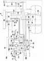
图1是根据本发明的第一实施例的燃料蒸汽回收系统的液体燃料配送设备的图示;1 is an illustration of a liquid fuel dispensing device of a fuel vapor recovery system according to a first embodiment of the present invention;

图2是如图1所示的燃料配送器的图示;Figure 2 is an illustration of the fuel dispenser shown in Figure 1;

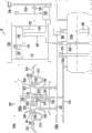
图3是示出如图2所示的燃料配送器单元的某些操作特征的示意图;Figure 3 is a schematic diagram illustrating certain operational features of the fuel dispenser unit shown in Figure 2;

图4是根据本发明的替代实施例的包括燃料蒸汽回收系统的液体燃料配送设备的图示;4 is an illustration of a liquid fuel dispensing apparatus including a fuel vapor recovery system according to an alternative embodiment of the present invention;

图5是示出如图4所示的燃料配送器的某些操作特征的示意图;Figure 5 is a schematic diagram illustrating certain operational features of the fuel dispenser shown in Figure 4;

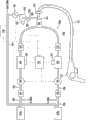
图6是根据本发明的替代实施例的包括燃料蒸汽回收系统的液体燃料配送设备的图示;Figure 6 is an illustration of a liquid fuel dispensing apparatus including a fuel vapor recovery system according to an alternate embodiment of the present invention;

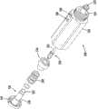
图7是可以用于如图1、4和6所示的燃料蒸汽回收系统中的空气液体蒸汽调节阀的部分地分解的透视图;Figure 7 is a partially exploded perspective view of an air liquid vapor regulating valve that may be used in the fuel vapor recovery system shown in Figures 1, 4 and 6;

图8A和8B是如图6所示的空气液体蒸汽调节阀的横截面视图;以及8A and 8B are cross-sectional views of the air-liquid-vapor regulating valve shown in FIG. 6; and

图9A和9B是示出在图7、8A和8B中的阀中的流调节机构的操作的图形。9A and 9B are graphs illustrating the operation of the flow regulating mechanism in the valve in FIGS. 7, 8A and 8B.

在本说明书和附图中,附图标记的重复使用意在表示本发明的相同或者类似特征或者元件。Repeat use of reference characters in the present specification and drawings is intended to represent same or analogous features or elements of the invention.

具体实施方式Detailed ways

现将对本发明的当前优选的实施例进行详细的描述,实施例的一个或多个例子示出在附图中。每个例子是通过解释本发明而提供,而不是限制本发明。事实上,对于本领域技术人员来说明显的是,可以在本发明中进行各种修改和变化而不超出其范围和实质。例如,作为一个实施例的一部分示出或描述的特征可以用于另一实施例以产生又另一实施例。因此,意在的是,本发明覆盖这样的修改和变化,其落在所附权利要求及其等同物的范围内。Reference will now be made in detail to the presently preferred embodiments of the invention, one or more examples of which are illustrated in the accompanying drawings. Each example is provided by way of explanation of the invention, not limitation of the invention. In fact, it will be apparent to those skilled in the art that various modifications and changes can be made in the present invention without departing from the scope and spirit thereof. For example, features illustrated or described as part of one embodiment can be used with another embodiment to yield yet a further embodiment. Thus, it is intended that the present invention covers the modifications and variations that come within the scope of the appended claims and their equivalents.

参照图1描述本发明的第一实施例,图1示出根据本发明的用于液体燃料配送设备10的蒸汽回收系统。如所示,燃料配送设备10包括站壳体100、一个或多个燃料配送器单元200a和200b(燃料配送器单元200b未示出)、主燃料存储系统300、用于连接燃料配送器单元200a和200b到主燃料存储系统300的装置以及一个或多个蒸汽(或者空气)流量传感器(AFS的)501。燃料配送器单元200a和200b可以是北卡罗来纳州的Gilbarco,inc.of Greensboro售卖的

Figure BDA00001769177100041
或者其它的燃料配送器,例如在美国专利No.4,978,029中公开的,该美国专利在此通过引用而全文并入。A first embodiment of the present invention is described with reference to Fig. 1, which shows a vapor recovery system for a liquidfuel dispensing device 10 according to the present invention. As shown, thefuel dispensing apparatus 10 includes astation housing 100, one or morefuel dispenser units 200a and 200b (fuel dispenser unit 200b not shown), a primaryfuel storage system 300, afuel dispenser unit 200a for connection to and 200b to the mainfuel storage system 300 and one or more vapor (or air) flow sensors (AFS) 501 .Fuel dispenser units 200a and 200b may be sold by Gilbarco, Inc. of Greensboro, North Carolina
Figure BDA00001769177100041
or other fuel dispensers, such as disclosed in US Patent No. 4,978,029, which is hereby incorporated by reference in its entirety.

如图1所示,站壳体100包括:中心电子控制系统110,其包括配送器控制器120(也称作现场控制器或者售卖点(point-of-sale)系统);连接配送器控制器120与燃料配送器单元200a和200b的配送器电流环接口缆线130;以及数据采集系统140。配送器控制器120控制燃料配送器单元200a和200b并处理通过电流环130从配送器200接收的交易信息。配送器控制器120与数据采集系统140例如通过第一缆线总线122电连通。接口缆线130可以通过第二缆线总线132电连接到数据采集系统140。配送器控制器120可以为Gilbarco

Figure BDA00001769177100042
或者
Figure BDA00001769177100043
售卖点系统。As shown in FIG. 1 , thestation housing 100 includes: a centralelectronic control system 110 that includes a dispenser controller 120 (also referred to as a site controller or point-of-sale system); 120 to the dispenser currentloop interface cable 130 of thefuel dispenser units 200a and 200b; and thedata acquisition system 140. Thedispenser controller 120 controls thefuel dispenser units 200 a and 200 b and processes transaction information received from thedispenser 200 through thecurrent loop 130 .Dispenser controller 120 is in electrical communication withdata acquisition system 140 , eg, viafirst cable bus 122 .Interface cable 130 may be electrically connected todata acquisition system 140 throughsecond cable bus 132 .Dispenser controller 120 can be Gilbarco
Figure BDA00001769177100042
or
Figure BDA00001769177100043
Point of sale system.

数据采集系统140优选地包括标准的计算机存储和中央处理能力、键盘输入装置以及音频和视频输出接口以及其它传统特征。诸如加利福利亚空气资源局(CARB)的单位已经提出对提高的蒸汽回收(EVR)设备的要求。这包括严格的蒸汽回收系统监测要求以持续确定系统是否正常工作。在受制于这些提高的要求的地方,数据采集系统140还可以用作站内诊断监测器。例如,如果需要,数据采集系统140可以为Veeder-Root CompanyTLS-350TM罐监测器。配送器控制器120和数据采集系统140二者可以进一步连通耦合到远离现场或者远程系统(未示出),用于远程通信和接收指令,在该情形下,两个系统都可以通过电话线或者其它网络线路,包括互联网,与远程系统通信。Data acquisition system 140 preferably includes standard computer storage and central processing capabilities, keyboard input devices, and audio and video output interfaces, among other conventional features. Organizations such as the California Air Resources Board (CARB) have placed requirements for enhanced vapor recovery (EVR) equipment. This includes stringent vapor recovery system monitoring requirements to continually determine that the system is functioning properly. Where subject to these heightened requirements, thedata acquisition system 140 can also be used as an on-site diagnostic monitor. For example, thedata acquisition system 140 can be a Veeder-Root Company TLS-350 Tank Monitor, if desired. Both thedispenser controller 120 and thedata acquisition system 140 may be further communicatively coupled to an off-site or remote system (not shown) for remote communication and receiving instructions, in which case both systems may be via a telephone line or Other network lines, including the Internet, communicate with remote systems.

此外,参照图2和3,燃料配送器单元200a和200b可以以传统的“燃油泵”的形式提供。每一燃料配送器单元200a和200b可包括典型地由喷嘴210限定的一个或多个燃料配送点。在所示的优选实施例中,燃料喷嘴210是与机械的空气液体蒸汽调节阀500(此后称作A/L调节阀)结合使用的适当的蒸汽回收喷嘴,例如如图7、8A和8B所示的。A/L调节阀500的操作在下面更详细地讨论。Furthermore, referring to Figures 2 and 3, thefuel dispenser units 200a and 200b may be provided in the form of conventional "fuel pumps". Eachfuel dispenser unit 200a and 200b may include one or more fuel dispensing points, typically defined bynozzles 210 . In the preferred embodiment shown, thefuel nozzle 210 is a suitable vapor recovery nozzle used in conjunction with a mechanical air-liquid vapor regulating valve 500 (hereinafter referred to as an A/L regulating valve), such as shown in FIGS. 7, 8A and 8B. shown. Operation of the A/L regulator valve 500 is discussed in more detail below.

燃料配送器单元200a和200b的每个燃料配送点包括混合歧管260、同轴蒸汽/液体分离器261、蒸汽返回通道220、燃料供应通道230和机械A/L调节阀500。如所示,机械A/L调节阀500优选地布置为与同轴蒸汽/液体分离器261相邻。蒸汽返回通道220可以在与共用的蒸汽返回管410(图1)连接以前结合在一起。Each fuel dispensing point offuel dispenser units 200a and 200b includes mixingmanifold 260 , coaxial vapor/liquid separator 261 ,vapor return channel 220 ,fuel supply channel 230 and mechanical A/L regulator valve 500 . As shown, the mechanical A/L regulator valve 500 is preferably disposed adjacent to the coaxial vapor/liquid separator 261 . Thesteam return channels 220 may be joined together prior to connection with the common steam return pipe 410 (FIG. 1).

燃料配送器单元200a和200b还包括液体燃料配送计240。液体燃料配送计240经由液体燃料配送计接口270或者控制系统以及接口缆线130提供配送的液体燃料数量信息给配送器控制器120。控制系统270可以为微控制器、微处理器或者与相关的存储器以及在其上运行的软件程序相关的其它的电子元器件。控制系统270典型地基于从液体燃料配送计240接收的燃油信息控制燃料配送器单元200a和200b的各个方面,例如加仑(或者升)显示器215、价格显示器216、付款交易收条等。Thefuel dispenser units 200a and 200b also include a liquidfuel dispenser gauge 240 . Liquidfuel dispensing gauge 240 providesdispenser controller 120 with liquid fuel quantity information via liquid fuel dispensinggauge interface 270 or control system andinterface cable 130 .Control system 270 may be a microcontroller, microprocessor, or other electronic component with associated memory and software programs running thereon.Control system 270 typically controls various aspects offuel dispenser units 200a and 200b such as gallon (or liter)display 215,price display 216, payment transaction receipts, etc. based on fuel information received from liquidfuel dispenser gauge 240.

主燃料存储系统300包括一个或多个主燃料存储罐310a和310b。燃料储存箱310a和310b典型地设置在地下,但是本发明的应用并不要求罐布置在地下。如在图1中最好地示出,每个燃料存储罐310a和310b通过通风管320连接到大气。通风管320端接在减压阀330中。蒸汽处理器340可连接到燃料存储罐310a和310b与减压阀330中间的通风管320。注意到,在并不受制于提高的监测要求的场所,典型地并不需要蒸汽处理器。在这种情况中,压力传感器350可操作地连接到通风管320。燃料存储罐310a和310b还可包括用于提供关于存储罐中的燃料液位的自动罐计量系统(ATGS)360。蒸汽处理器340、压力传感器350和自动罐计量系统360分别通过第三、第四和第五缆线总线342,352和362电连接到数据采集系统140。燃料存储罐310a和310b还包括充填管和充填导管370以提供给罐充填燃料的装置和浸没式泵380以从存储罐310a和310b给配送器200a和200b供应燃料。Primaryfuel storage system 300 includes one or more primaryfuel storage tanks 310a and 310b.Fuel storage tanks 310a and 310b are typically located underground, but the application of the present invention does not require the tanks to be located underground. As best shown in FIG. 1 , eachfuel storage tank 310 a and 310 b is connected to atmosphere by avent tube 320 . Thevent tube 320 terminates in apressure relief valve 330 . Thesteam processor 340 may be connected to theventilation pipe 320 between thefuel storage tanks 310 a and 310 b and thedecompression valve 330 . Note that steam handlers are typically not required in locations that are not subject to increased monitoring requirements. In this case, thepressure sensor 350 is operatively connected to thevent tube 320 . Thefuel storage tanks 310a and 310b may also include an automatic tank gauging system (ATGS) 360 for providing information about the fuel level in the storage tanks.Vapor processor 340,pressure sensor 350 and automatictank gauging system 360 are electrically connected todata acquisition system 140 via third, fourth andfifth cable buses 342, 352 and 362, respectively.Fuel storage tanks 310a and 310b also include fill tubes and fillconduits 370 to provide means for filling the tanks with fuel andsubmersible pumps 380 to supply fuel fromstorage tanks 310a and 310b todispensers 200a and 200b.

用于连接燃料配送器单元200a和200b与主燃料存储系统300的装置包括蒸汽返回管道410和一个或多个燃料供应管道420。与多个燃料配送点210相关联,蒸汽返回管道410和燃料供应管道420分别连接到蒸汽返回通道220和燃料供应通道230。燃料供应管道420可以是具有二次密闭室的双壁管,如熟知的。示例性的地下燃料递送系统示出在美国专利No.6,435,204中,该专利在此通过引用而全文并入。Means for connecting thefuel dispenser units 200a and 200b to the mainfuel storage system 300 includes avapor return conduit 410 and one or morefuel supply conduits 420 . Associated with the plurality of fuel distribution points 210, avapor return conduit 410 and afuel supply conduit 420 are connected to thevapor return passage 220 and thefuel supply passage 230, respectively.Fuel supply conduit 420 may be a double walled tube with a secondary containment chamber, as is well known. An exemplary underground fuel delivery system is shown in US Patent No. 6,435,204, which is hereby incorporated by reference in its entirety.

在图1所示的实施例中,通过电机252驱动的可变速蒸汽泵250通过共用的蒸汽返回管道410耦合到多个蒸汽返回通道220以帮助燃料蒸汽的回收。在所示的优选实施例中,可变速蒸汽泵250可以是Healy VP

Figure BDA00001769177100061
该系统的例子在美国专利No.5,040,577中有提及,该美国专利在此通过引用而全文引入。数据采集系统140从布置在蒸汽泵250的入口侧并通过接口导线257电连接到数据采集系统140的压力传感器253接收关于蒸汽返回管道410中的压力的信息。In the embodiment shown in FIG. 1 , variablespeed vapor pump 250 driven bymotor 252 is coupled to plurality of vapor returnpassages 220 through commonvapor return conduit 410 to facilitate fuel vapor recovery. In the preferred embodiment shown, variablespeed steam pump 250 may be a Healy VP
Figure BDA00001769177100061
An example of such a system is mentioned in US Patent No. 5,040,577, which is hereby incorporated by reference in its entirety. Thedata acquisition system 140 receives information about the pressure in thesteam return line 410 from apressure sensor 253 arranged at the inlet side of thesteam pump 250 and electrically connected to thedata acquisition system 140 through aninterface wire 257 .

如图1所示,AFS501布置在蒸汽返回通道220的共用分支中以测量各组燃料配送点210的蒸汽流,低至最少仅两个配送点蒸汽流。后一例子通过在每个燃料配送器单元200a和200b中安装一个AFS501而实现,每个燃料配送器单元典型地包含两个配送点210(配送器每一侧一个配送点),如所示的,或者在多产品配送器(MPD's)中多至六个配送点(每一侧3个)。从管中通过蒸汽返回通道220的蒸汽流被组合以通过配送器壳体中的单个AFS501。但是,替代实施例可以包括专用于每个个体的燃料配送点210的AFS501以使得每个AFS501测量来自个体的燃料配送点210的蒸汽流。注意到,在不受制于提高的监测要求的场所,典型地并不需要空气流传感器。As shown in Figure 1, theAFS 501 is placed in a common branch of thevapor return channel 220 to measure the vapor flow for each set of fuel distribution points 210, down to a minimum of only two distribution point vapor flows. The latter example is accomplished by installing oneAFS 501 in eachfuel dispenser unit 200a and 200b, each fuel dispenser unit typically containing two distribution points 210 (one on each side of the dispenser), as shown , or up to six distribution points (3 on each side) in Multiple Product Dispensers (MPD's). The steam flow from the tube through thesteam return channel 220 is combined to pass through asingle AFS 501 in the dispenser housing. However, alternative embodiments may include anAFS 501 dedicated to each individualfuel distribution point 210 such that eachAFS 501 measures vapor flow from the individualfuel distribution point 210 . Note that air flow sensors are typically not required in locations that are not subject to increased monitoring requirements.

额外地参照图3,本发明的一个例子的内部燃料流部件被示出。如前提及的,燃料从一个或者多个地下燃料存储罐310a和310b经由与它们各自的地下存储罐相关联的燃料供应管道420移动。燃料供应管道420通过剪切阀421(图2)通入到燃料配送器单元200a的壳体202中。如行业中公知的,如果燃料配送器单元200受到冲击,剪切阀421设计为切断流动通过它们各自的燃料供应管道420的燃料。剪切阀的示例性实施例公开在美国专利No.6,575,206中,该美国专利在此通过引用而全文并入。类似地,蒸汽返回通道220通过剪切阀221从燃料配送器单元200a中通出来(图2)。With additional reference to FIG. 3 , an internal fuel flow component of an example of the present invention is shown. As previously mentioned, fuel is moved from one or more undergroundfuel storage tanks 310a and 310b viafuel supply conduits 420 associated with their respective underground storage tanks. Thefuel supply line 420 opens into thehousing 202 of thefuel dispenser unit 200a through a shear valve 421 ( FIG. 2 ). As is known in the industry, theshear valves 421 are designed to shut off fuel flow through their respectivefuel supply conduits 420 if thefuel dispenser unit 200 is impacted. Exemplary embodiments of shear valves are disclosed in US Patent No. 6,575,206, which is hereby incorporated by reference in its entirety. Similarly,vapor return passage 220 exitsfuel dispenser unit 200a through shear valve 221 (FIG. 2).

如图3所示,从地下燃料存储罐310a和310b到燃料喷嘴210的燃料流动路径每个包括燃料过滤器246和沿着液体燃料配送计240的燃料线路230上游定位的比例阀244。或者,比例阀244可定位在液体燃料配送计240的下游。液体燃料配送计240和比例阀244定位在壳体202的燃料处理舱室203中。燃料处理舱室203与定位在蒸汽障碍件205的上方的电子元器件舱室隔离。燃料处理舱室203与可能导致燃料蒸汽燃烧的火花或其它事件隔离,如熟知的以及如在美国专利No.5,717,564中描述的,该美国专利在此通过引用而全文并入。As shown in FIG. 3 , the fuel flow paths from undergroundfuel storage tanks 310 a and 310 b to fuelnozzles 210 each include afuel filter 246 and aproportional valve 244 positioned upstream alongfuel line 230 of liquidfuel dispensing meter 240 . Alternatively,proportional valve 244 may be positioned downstream of liquidfuel dispensing meter 240 . Liquidfuel dispensing gauge 240 andproportional valve 244 are positioned infuel processing compartment 203 ofhousing 202 . Thefuel processing compartment 203 is isolated from the electronics compartment positioned above thevapor barrier 205 . Thefuel processing chamber 203 is isolated from sparks or other events that could cause combustion of fuel vapors, as is well known and as described in US Patent No. 5,717,564, which is hereby incorporated by reference in its entirety.

液体燃料配送计240经由从脉冲器241到控制系统270的脉冲器信号线与蒸汽障碍件205连通。控制系统270经由阀连通线调节比例阀244,以在加燃料操作中打开和关闭。比例阀244可以是比例电磁线圈控制阀,例如在美国专利No.5,954,080中描述的,该美国专利在此通过引用而全文并入。当控制系统270控制比例阀244以打开以允许增大燃料流时,燃料进入比例阀244中并存在于液体燃料配送器计240中。燃料的排出体积(displaced volumn)的流量通过液体燃料配送器计240测量,该液体燃料配送器计240经由脉冲器信号线将燃料的排出体积流量传递给控制系统270。在所示例子中,例如通过霍尔效应,脉冲信号产生在脉冲器信号线上,如在美国专利No.7,028,561中描述的。该美国专利在此通过引用而全文并入。这样,控制系统270使用来自脉冲器信号线的脉冲器信号以确定流动通过燃料配送器单元200a并递送给车辆12的燃料的流量。控制系统270经由加仑显示通信线路更新加仑显示器215上配送的总加仑数,以及经由价格显示通信线路更新在价格显示器216上配送的燃料的费用。Liquidfuel dispensing gauge 240 communicates withvapor barrier 205 via a pulser signal line frompulser 241 to controlsystem 270 .Control system 270 regulatesproportional valve 244 via a valve communication line to open and close during fueling operations.Proportional valve 244 may be a proportional solenoid control valve such as that described in US Patent No. 5,954,080, which is hereby incorporated by reference in its entirety. Fuel entersproportional valve 244 and is present in liquidfuel dispenser gauge 240 whencontrol system 270 controlsproportional valve 244 to open to allow increased fuel flow. The flow of the displaced volume of fuel is measured by a liquidfuel dispenser meter 240 which communicates the displaced volume flow of fuel to thecontrol system 270 via the pulser signal line. In the example shown, a pulsed signal is generated on a pulser signal line, such as by the Hall effect, as described in US Patent No. 7,028,561. This US patent is hereby incorporated by reference in its entirety. In this manner, thecontrol system 270 uses the pulser signal from the pulser signal line to determine the flow rate of fuel flowing through thefuel dispenser unit 200a and delivered to thevehicle 12 . Thecontrol system 270 updates the total number of gallons dispensed on thegallon display 215 via the gallon display communication link, and updates the cost of fuel dispensed on theprice display 216 via the price display communication link.

随着燃料离开液体燃料配送计240,燃料进入流开关(flow switch)242。流开关242经由流开关信号线产生流开关通信信号给控制系统270以传达燃料何时流动通过液体燃料配送计240。流开关通信信号为控制系统270表明燃料实际地在燃料递送路径中流动并且随后的来自液体燃料配送计240的脉冲器信号是由于实际的燃料流。As fuel exits liquid fuel dispensegauge 240, fuel entersflow switch 242.Flow switch 242 generates a flow switch communication signal to controlsystem 270 via a flow switch signal line to communicate when fuel is flowing through liquid fuel dispensemeter 240 . The flow switch communication signal indicates to thecontrol system 270 that fuel is actually flowing in the fuel delivery path and that the subsequent pulser signal from the liquidfuel dispensing meter 240 is due to actual fuel flow.

在燃料进入流开关242后,它通过燃料供应通道230退出以递送到混合歧管260。混合歧管260接收来自各地下燃料存储罐310a和310b的不同辛烷值的燃料并保证由消费者选择的辛烷值的燃料被递送到消费者的车辆12。在流动通过混合歧管260后,燃料通过燃料软管212和燃料喷嘴210,以便递送到车辆12的燃料罐24中。柔性的燃料软管212包括产品递送管线231和蒸汽返回通道220。线路231和220二者通过燃料配送器单元200a液体连接到地下燃料存储罐310a和310b,如以前讨论的。蒸汽返回通道220通过同轴蒸汽/液体分离器261与产品递送管线231分离。After fuel entersflow switch 242 , it exits throughfuel supply passage 230 for delivery to mixingmanifold 260 . The mixingmanifold 260 receives fuel of different octane ratings from each of the undergroundfuel storage tanks 310 a and 310 b and ensures that the fuel of the octane rating selected by the customer is delivered to the customer'svehicle 12 . After flowing through mixingmanifold 260 , fuel passes throughfuel hose 212 andfuel nozzle 210 for delivery intofuel tank 24 ofvehicle 12 .Flexible fuel hose 212 includesproduct delivery line 231 andvapor return channel 220 . Bothlines 231 and 220 are fluidly connected to undergroundfuel storage tanks 310a and 310b throughfuel dispenser unit 200a, as previously discussed. Thevapor return channel 220 is separated from theproduct delivery line 231 by a coaxial vapor/liquid separator 261 .

在燃料递送到车辆的燃料罐24过程中,正进入的燃料将燃料罐24中的包含燃料蒸汽的空气置换。蒸汽在蒸汽泵250的帮助下从车辆12的燃料罐24通过蒸汽返回通道220回收。如前所述,本实施例的蒸汽泵250是可变速泵。当燃料从燃料喷嘴210配送到车辆12的燃料罐24中时,流动的燃料导致机械A/L调节阀500打开,从而打开到燃料罐24的蒸汽返回通道220。During fuel delivery to thefuel tank 24 of the vehicle, the incoming fuel displaces air in thefuel tank 24 that contains fuel vapors. Vapor is recovered from thefuel tank 24 of thevehicle 12 through thevapor return passage 220 with the aid of thevapor pump 250 . As previously mentioned, thesteam pump 250 of this embodiment is a variable speed pump. When fuel is dispensed fromfuel nozzle 210 intofuel tank 24 ofvehicle 12 , the flowing fuel causes mechanical A/L regulator valve 500 to open, thereby openingvapor return passage 220 tofuel tank 24 .

更具体地,额外参照图7,8A和8B,A/L调节阀500包括液体活塞510、蒸汽活塞520、蒸汽管530和弹簧540,它们全部容纳在壳体550内。此外,A/L调节阀500包括高流量调节机构560和低流量调节机构580,用于调节关于配送的给定量的燃料而回收的蒸汽的量,如在下面更详细讨论的。如在图8A和8B中最好地看出,壳体550限定沿着它的的长度中心轴的蒸汽流动路径552,其包括在它的末端的蒸汽返回口554。此外壳体550限定大致圆柱形状并与蒸汽流动路径552同心的燃料流动路径556。壳体550配置为以使得蒸汽流动路径552与蒸汽返回通道220流体连通并且燃料流动路径556与柔性燃料软管212的产品递送线路231流体连通(图2)。More specifically, with additional reference to FIGS. 7 , 8A and 8B , the A/L regulator valve 500 includes aliquid piston 510 , asteam piston 520 , asteam tube 530 and aspring 540 , all contained within ahousing 550 . Additionally, A/L regulator valve 500 includes a highflow regulation mechanism 560 and a lowflow regulation mechanism 580 for regulating the amount of vapor recovered for a given amount of fuel delivered, as discussed in more detail below. As best seen in FIGS. 8A and 8B ,housing 550 defines asteam flow path 552 along its length central axis, which includes asteam return port 554 at its end.Further housing 550 defines afuel flow path 556 that is generally cylindrical in shape and concentric withvapor flow path 552 .Housing 550 is configured such thatvapor flow path 552 is in fluid communication withvapor return passage 220 andfuel flow path 556 is in fluid communication withproduct delivery line 231 of flexible fuel hose 212 ( FIG. 2 ).

蒸汽管530包括第一末端532、第二末端534和在它们之间延伸的圆柱部分536。蒸汽管530的第一末端532围绕蒸汽流动路径552和蒸汽返回口554同心地接收在壳体550中。在该实施例中,蒸汽管530通过围绕蒸汽管530的第二末端534形成的环形唇状件537保持在壳体550中,所述环形唇状件537与围绕壳体550的内表面形成的环形凹槽538相互作用。因此,蒸汽管530的圆柱部分536形成蒸汽返回路径552的一部分。Steam tube 530 includes afirst end 532, asecond end 534, and acylindrical portion 536 extending therebetween.First end 532 ofsteam tube 530 is received concentrically inhousing 550 aboutsteam flow path 552 andsteam return port 554 . In this embodiment, thesteam tube 530 is retained in thehousing 550 by anannular lip 537 formed around thesecond end 534 of thesteam tube 530 , which is in contact with anannular lip 537 formed around the inner surface of thehousing 550 .Annular grooves 538 interact. Thus, thecylindrical portion 536 of thesteam tube 530 forms part of thesteam return path 552 .

蒸汽活塞520包括计量元件或者鼻状件522,以及布置在梭状(shuttle)主体526上的磁体524。蒸汽活塞520可滑动地接收在蒸汽管530的圆柱部分536内以使得蒸汽活塞520在蒸汽管530内的来回运动使得计量鼻状件522调节通过蒸汽返回口554的燃料蒸汽流。Thesteam piston 520 includes a metering element ornose 522 and amagnet 524 arranged on ashuttle body 526 .Vapor piston 520 is slidably received withincylindrical portion 536 ofvapor tube 530 such that reciprocating movement ofvapor piston 520 withinvapor tube 530 causesmetering nose 522 to regulate fuel vapor flow throughvapor return port 554 .

液体活塞510包括磁体512并沿着蒸汽管530的外表面可滑动地安装。弹簧540同样围绕蒸汽管520的外表面安装并安置为以使得液体活塞510被推入到闭合位置(图8A)。类似地,液体活塞510的磁体512与蒸汽活塞520的磁体524的相互作用保证当液体活塞510处于闭合位置时,蒸汽活塞520的计量鼻状件522完全位于蒸汽返回口554中。Theliquid piston 510 includes amagnet 512 and is slidably mounted along the outer surface of thevapor tube 530 . Aspring 540 is also mounted around the outer surface of thevapor tube 520 and positioned such that theliquid piston 510 is urged into the closed position (Fig. 8A). Similarly, the interaction of themagnet 512 of theliquid piston 510 with themagnet 524 of thevapor piston 520 ensures that themetering nose 522 of thevapor piston 520 is fully seated in thevapor return port 554 when theliquid piston 510 is in the closed position.

高流量调节机构560包括可转动地接收在由壳体550限定的第一孔558中的高流量调节螺丝562。高流量调节螺丝562包括接收在第一孔558的光滑部分中的头部564和接收在第一孔558的相应的螺纹部分中的螺纹柄566。如此,高流量调节螺丝562的转动使得高流量调节螺丝562沿着第一孔558的纵轴移动,从而使得螺纹柄566的远端568要么更往前地突入到蒸汽返回路径552中,要么从蒸汽返回路径552退出。这样,高流量调节螺丝562可以用于调节关于以给定流量配送的给定量的燃料而回收的蒸汽的量,如在下面更详细地讨论的。Highflow adjustment mechanism 560 includes a highflow adjustment screw 562 rotatably received infirst bore 558 defined byhousing 550 . Highflow adjustment screw 562 includes ahead 564 received in a smooth portion offirst bore 558 and a threadedshank 566 received in a corresponding threaded portion offirst bore 558 . As such, rotation of the highflow adjustment screw 562 causes the highflow adjustment screw 562 to move along the longitudinal axis of thefirst bore 558 such that thedistal end 568 of the threadedshank 566 either protrudes further forward into thesteam return path 552 or out of thesteam return path 552.Steam return path 552 exits. As such, the highflow adjustment screw 562 may be used to adjust the amount of vapor recovered for a given amount of fuel dispensed at a given flow rate, as discussed in more detail below.

低流量调节机构580包括可转动地接收在由壳体550限定的第二孔559中的低流量调节螺丝582,以及与蒸汽返回口554的上游和下游二者的蒸汽流动路径552的一部分流体连通的蒸汽流旁路590。低流量调节螺丝582包括接收在第二孔559的光滑部分中的头部584和接收在第二孔559的相应螺纹部分中的螺纹柄586。如此,低流量调节螺旋582在第二孔559中的转动使得低流量调节螺丝582沿着第二孔559的纵轴运动,从而使得螺纹柄586的远端588要么往前突入到蒸汽流旁路590中,要么从蒸汽流旁路590退出。这样,低流量调节螺丝582可以用于调节在加燃料操作过程中被允许绕过蒸汽返回口554的蒸汽的量。注意到,低流量调节螺丝582的远端588可以完全位于蒸汽流旁路590的一部分内,以使得防止蒸汽流动通过蒸汽流旁路590。Lowflow adjustment mechanism 580 includes a lowflow adjustment screw 582 rotatably received insecond bore 559 defined byhousing 550 and in fluid communication with a portion ofsteam flow path 552 both upstream and downstream ofsteam return port 554steam flow bypass 590. Lowflow adjustment screw 582 includes ahead 584 received in a smooth portion ofsecond bore 559 and a threadedshank 586 received in a corresponding threaded portion ofsecond bore 559 . As such, rotation of the lowflow adjustment screw 582 in thesecond bore 559 causes the lowflow adjustment screw 582 to move along the longitudinal axis of thesecond bore 559 such that thedistal end 588 of the threadedshank 586 either protrudes forward into thevapor flow bypass 590, or exit fromsteam flow bypass 590. As such, the lowflow adjustment screw 582 may be used to adjust the amount of steam that is allowed to bypass thesteam return port 554 during fueling operations. Note that thedistal end 588 of the lowflow adjustment screw 582 may be located entirely within a portion of thesteam flow bypass 590 such that steam flow through thesteam flow bypass 590 is prevented.

在使用中,用户促动燃料喷嘴210,从而使得加压的燃料进入到A/L调节阀500的燃料流动路径556中,如上所述。如在图7A中最好地示出的,加压燃料作用在液体活塞510的第一末端514的表面区域上,克服弹簧540的偏压力。最终,由燃料施加的力克服弹簧540的偏压力而使得液体活塞510沿着蒸汽管530的圆柱部分536的外表面滑动,从而打开燃料流动路径556并允许燃料流入车辆的燃料罐24中。随着液体活塞510沿着蒸汽管530滑动,由于蒸汽活塞520的磁体524与液体活塞510的磁体512的相互作用,蒸汽活塞520类似地沿着蒸汽管530的圆柱部分536的内表面滑动。如此,蒸汽活塞520的计量鼻状件522从蒸汽返回口554退出,并且蒸汽流动路径552现开口到车辆的燃料罐24的内部空间,如图7B所示。In use, a user actuatesfuel nozzle 210 , causing pressurized fuel to enterfuel flow path 556 of A/L regulator valve 500 , as described above. As best shown in FIG. 7A , the pressurized fuel acts on the surface area of thefirst end 514 of theliquid piston 510 against the biasing force of thespring 540 . Eventually, the force exerted by the fuel overcomes the biasing force ofspring 540 to causeliquid piston 510 to slide along the outer surface ofcylindrical portion 536 ofvapor tube 530 , thereby openingfuel flow path 556 and allowing fuel to flow intofuel tank 24 of the vehicle. As theliquid piston 510 slides along thesteam tube 530 , thesteam piston 520 similarly slides along the inner surface of thecylindrical portion 536 of thesteam tube 530 due to the interaction of themagnet 524 of thesteam piston 520 with themagnet 512 of theliquid piston 510 . As such, themetering nose 522 of thevapor piston 520 exits thevapor return port 554 and thevapor flow path 552 now opens to the interior space of the vehicle'sfuel tank 24, as shown in FIG. 7B.

由蒸汽泵250保持的真空使得通过燃料进入燃料罐24中而位移的混有蒸汽的空气通过A/L调节阀500而被抽取到蒸汽返回通道220中。如上所述,随着燃料配送的流量增大,A/L调节阀500的蒸汽活塞进一步打开,并且更多的空气被抽入到蒸汽返回通道220以及相关的蒸汽返回管道410中。The vacuum maintained by thevapor pump 250 causes the vapor-entrained air displaced by the entry of fuel into thefuel tank 24 to be drawn into thevapor return passage 220 through the A/L regulator valve 500 . As described above, as the flow rate of fuel delivery increases, the vapor piston of A/L regulator valve 500 opens further and more air is drawn intovapor return passage 220 and associatedvapor return conduit 410 .

测试表明,当低至80毫巴的真空水平保持在A/L调节阀500的下游侧上时,公开的系统能如期望地工作。但是,在蒸汽回收过程中,少量的燃料可能通过相关联的喷嘴210被抽入到蒸汽返回通道220中。该燃料趋于收集在相关联的蒸汽返回通道220的最低部分中,从而如果燃料不被清除的话则有效地阻挡蒸汽返回通道220并防止进一步的蒸汽回收。尽管当80毫巴的真空被保持时适当的蒸汽回收通过清空蒸汽返回通道220而实现,但是,80毫巴的真空典型地并大到足以保证任何的吸入燃料通过蒸汽泵250被进一步抽取以使得蒸汽返回通道220保持通畅并且蒸汽回收继续。如此,优选地,在本实施例中,大约200毫巴的真空可以保持在A/L调节阀500的下游侧。注意到,也可以使用更高的真空水平,只要它们足以保持蒸汽返回通道220处于畅通状态。Testing has shown that the disclosed system works as expected when vacuum levels as low as 80 mbar are maintained on the downstream side of the A/L regulator valve 500 . However, during vapor recovery, a small amount of fuel may be drawn into thevapor return passage 220 through the associatednozzle 210 . This fuel tends to collect in the lowest portion of the associatedvapor return passage 220, effectively blocking thevapor return passage 220 and preventing further vapor recovery if the fuel is not purged. Although proper vapor recovery is achieved by emptying thevapor return passage 220 when a vacuum of 80 millibars is maintained, a vacuum of 80 millibars is typically not large enough to ensure that any suction fuel is further drawn through thevapor pump 250 so that Thevapor return channel 220 remains open and vapor recovery continues. As such, preferably, a vacuum of about 200 mbar can be maintained on the downstream side of the A/L regulating valve 500 in the present embodiment. Note that higher vacuum levels can also be used as long as they are sufficient to keep thevapor return channel 220 clear.

图9A和9B是示出高流量调节机构560和低流量调节机构580可以如何单独或组合使用以调节关于给定量的配送燃料而回收的蒸汽的量从而调节相关的A/L调节阀500的A/L比率的图形。首先参照图9A,高流量调节机构560的使用被讨论。对于所示的示例性实施例,曲线600示出高流量调节机构560和低流量调节机构580的初始设置,其中当燃料正以每分钟40升的速率配送时1:1的期望A/L比率被实现。图8A和8B示出实现该A/L比率的A/L调节阀500的可能的构型,其中高流量调节螺丝562部分地延伸到蒸汽流动路径552中而低流量调节螺丝582部分地延伸到蒸汽流动旁路590中,从而部分地限制蒸汽流动。A/L调节阀500的期望的初始设置,即1:1的A/L比率,通过首先通过高流量调节机构560提供A/L比率的“粗”调节,然后通过低流量调节机构580精调A/L调节阀500的设置。9A and 9B are diagrams illustrating how the highflow adjustment mechanism 560 and the lowflow adjustment mechanism 580 may be used alone or in combination to adjust the amount of vapor recovered for a given amount of dispensed fuel to adjust the associated A/L adjustment valve 500. /L ratio graph. Referring first to Figure 9A, the use of a highflow adjustment mechanism 560 is discussed. For the exemplary embodiment shown,curve 600 shows the initial settings of highflow adjustment mechanism 560 and lowflow adjustment mechanism 580 with a desired A/L ratio of 1:1 when fuel is being dispensed at a rate of 40 liters per minute be realized. 8A and 8B show a possible configuration of the A/L adjustment valve 500 to achieve this A/L ratio, where the highflow adjustment screw 562 extends partially into thesteam flow path 552 and the lowflow adjustment screw 582 extends partially into thesteam flow path 552. Steam flows inbypass 590, thereby partially restricting steam flow. The desired initial setting of the A/L adjustment valve 500 , i.e. an A/L ratio of 1:1, is achieved by first providing a "coarse" adjustment of the A/L ratio via the highflow adjustment mechanism 560 followed by a fine adjustment via the low flow adjustment mechanism 580 A/L adjustment valve 500 setting.

在本例子中,曲线600表明,对于期望的初始设置,1:1的A/L比率在相关联的燃料配送点210的操作范围的相当大部分上得以保持(图2)。但是,注意到,可能有必要调节燃料配送点操作的A/L比率。实现关于A/L调节阀500的不同的A/L比率的一个方法反映在图9A的曲线610和620中。曲线610表明高流量调节螺丝562比在它的初始设置中更向前地延伸到蒸汽流动路径552中的结果,从而进一步限制蒸汽通过蒸汽流动路径552的流动。曲线610的与曲线600的斜率相比减小的斜率表明这样的事实:当与高流量调节螺丝562的实现1:1的A/L比率的初始设置相比时,对于给定量的配送的燃料更少的蒸汽被回收。In this example, thecurve 600 shows that, for the desired initial settings, a 1:1 A/L ratio is maintained over a substantial portion of the operating range of the associated fuel dispensing point 210 ( FIG. 2 ). Note, however, that it may be necessary to adjust the A/L ratio for fuel dispensing point operation. One method of achieving different A/L ratios with respect to A/L regulator valve 500 is reflected incurves 610 and 620 of FIG. 9A .Curve 610 shows the result of highflow adjustment screw 562 extending farther forward intosteam flow path 552 than in its initial setting, thereby further restricting the flow of steam throughsteam flow path 552 . The reduced slope ofcurve 610 compared to the slope ofcurve 600 indicates the fact that for a given amount of dispensed fuel Less steam is recovered.

类似地,关于给定量的配送的燃料而回收的蒸汽的量可以通过使得高调节螺丝562从蒸汽流动路径552与它的初始设置的情形相比更进一步地退出而增大,从而减少对通过蒸汽流动路径552的蒸汽流动的限制。曲线620的与曲线600的斜率相比更大的斜率表明这样的事实:与高流量调节螺丝562的初始设置相比,对于给定量的配送的燃料,更多的蒸汽被回收。Similarly, the amount of vapor recovered for a given amount of fuel dispensed can be increased by backing out thehigh adjustment screw 562 further from thevapor flow path 552 than it was at its initial setting, thereby reducing the Restriction of steam flow inflow path 552 . The greater slope ofcurve 620 compared to the slope ofcurve 600 indicates the fact that more vapor is recovered for a given amount of fuel dispensed compared to the initial setting of highflow adjustment screw 562 .

但是,曲线610和620的与初始设置的曲线600的斜率相比减小的斜率和增大的斜率分别表明这样的事实:随着配送燃料的速率降低,在相对于配送的燃料的量调节回收的蒸汽的量方面,高流量调节机构560变得更没效率。更具体地,对于讨论的优选实施例,在40升/分种的燃料配送速率下10升/分种的蒸汽流量调节导致在20升/分种的降低的燃料流率下每分钟大约1升的蒸汽流动。低流量调节机构580促进在燃料配送速率的整个范围内的回收的蒸汽量的调节。However, the reduced and increased slopes ofcurves 610 and 620 , respectively, compared to the initially set slope ofcurve 600 indicate the fact that as the rate at which fuel is dispensed decreases, recovery is adjusted relative to the amount of fuel dispensed. The highflow regulating mechanism 560 becomes less efficient in terms of the amount of steam that is More specifically, for the preferred embodiment discussed, a steam flow adjustment of 10 liters/minute at a fuel dispensing rate of 40 liters/minute results in approximately 1 liter per minute at a reduced fuel flow rate of 20 liters/minute of steam flow. The lowflow adjustment mechanism 580 facilitates adjustment of the amount of recovered vapor over the entire range of fuel delivery rates.

此外,参照图9B,讨论低流量调节机构580的使用。低流量调节机构580可以单独使用,或者与高流量调节机构560组合使用。图9B包括以前关于图9A讨论的曲线600,610和620,但是在此被重复以便于讨论低流量调节机构580如何可以用于调节回收的蒸汽的量。如前所述,对于所示的示例性实施例,曲线600示出高流量调节机构560和低流量调节机构580的初始设置,其中1:1的期望A/L比率在A/L调节阀500的操作范围的相当大部分上实现。In addition, referring to FIG. 9B , the use of a lowflow adjustment mechanism 580 is discussed. The lowflow adjustment mechanism 580 may be used alone or in combination with the highflow adjustment mechanism 560 . Figure 9B includescurves 600, 610, and 620 previously discussed with respect to Figure 9A, but are repeated here to facilitate discussion of how the lowflow adjustment mechanism 580 may be used to adjust the amount of recovered steam. As previously mentioned, for the exemplary embodiment shown,curve 600 shows the initial settings of highflow regulator mechanism 560 and lowflow regulator mechanism 580 with a desired A/L ratio of 1:1 at A/L regulator valve 500 A substantial portion of the operating range is achieved.

改变A/L调节阀500的A/L比率的一个方法反映在图9B的曲线602和612中。曲线602表明,低流量调节螺丝582从蒸汽流动旁路590比在它的初始设置中更进一步地退出,从而减小对通过蒸汽流动旁路590的蒸汽流的限制。但是,注意到,曲线602的斜率大致与曲线600的斜率相同。曲线600和602大致相似的斜率表明这样的事实:回收的蒸汽的增加量在配送燃料的速率的整个范围内大致相同。One method of changing the A/L ratio of A/L regulator valve 500 is reflected incurves 602 and 612 of FIG. 9B .Curve 602 shows that lowflow adjustment screw 582 is withdrawn further fromsteam flow bypass 590 than in its initial setting, thereby reducing the restriction on steam flow throughsteam flow bypass 590 . Note, however, that the slope ofcurve 602 is approximately the same as the slope ofcurve 600 . The approximately similar slopes ofcurves 600 and 602 indicate the fact that the increase in recovered vapor is approximately the same over the entire range of rates at which fuel is dispensed.

类似地,关于给定量的配送燃料而回收的蒸汽的量可以通过将低流量调节螺丝582比在它的初始位置更进一步地延伸到蒸汽流动旁路590中而减小,从而进一步限制通过蒸汽流动旁路590的蒸汽流。注意到,由曲线612代表的调节低流量调节螺丝582的“开始点”是曲线610,这意味着,在调节低流量调节螺丝582之前,高流量调节螺丝562已经从初始位置更早地调节,如关于图8A讨论的。曲线610和612的相似的斜率表明这样的事实:在配送燃料的速率的大致整个范围内更少的蒸汽被回收。曲线602和612示出在期望的曲线斜率已经通过利用高流量调节螺丝562实现后仅调节低流量调节螺丝582的结果。Similarly, the amount of vapor recovered for a given amount of dispensed fuel can be reduced by extending the lowflow adjustment screw 582 further into thevapor flow bypass 590 than in its original position, thereby further restricting the passage ofvapor flow Bypass 590 for steam flow. Note that the "start point" for adjusting the lowflow adjustment screw 582 represented by curve 612 iscurve 610, which means that the highflow adjustment screw 562 has been adjusted earlier from the initial position before the lowflow adjustment screw 582 is adjusted, As discussed with respect to Figure 8A. The similar slopes ofcurves 610 and 612 indicate the fact that less vapor is recovered over substantially the entire range of rates at which fuel is dispensed.Curves 602 and 612 show the results of adjusting only lowflow adjustment screw 582 after the desired slope of the curve has been achieved by utilizing highflow adjustment screw 562 .

现参照图9B的曲线622,讨论高流量调节机构560和低流量调节机构580二者的同时调节。当从曲线600开始时,通过调节高流量调节螺丝562和低流量调节螺丝582曲线622完成,曲线600示出1:1的A/L比率的初始设置。例如,更进一步地延伸高流量调节螺丝562到蒸汽流动路径552中限制蒸汽流动通过蒸汽流动路径552,从而与曲线600的斜率相比减小曲线622的斜率。然后,低流量调节螺丝582从蒸汽流动旁路590比在它的初始位置更进一步地退出。这导致在配送燃料的速率的整个范围内回收的蒸汽的增加量有效地导致整个曲线622向上移动,同时保持与通过调节高流动调整螺丝562实现的斜率大致相同的斜率。本实施例的最终结果是,与初始设置的曲线600相比,在降低的燃料配送速率例如每一分钟15升下,更多量的蒸汽流被回收,而在增大的燃料配送速率例如每一分钟35升下更少量的蒸汽被回收。如此,高流量调节机构560和低流量调节机构580的组合使用可以实现在相关联的燃料配送单元的整个操作范围上的多个A/L比率。Referring now tocurve 622 of FIG. 9B , simultaneous adjustment of both the highflow adjustment mechanism 560 and the lowflow adjustment mechanism 580 will be discussed. When starting fromcurve 600 and completingcurve 622 by adjusting highflow adjustment screw 562 and lowflow adjustment screw 582,curve 600 shows an initial setting of an A/L ratio of 1:1. For example, extending highflow adjustment screw 562 further intosteam flow path 552 restricts steam flow throughsteam flow path 552 , thereby reducing the slope ofcurve 622 compared to the slope ofcurve 600 . The lowflow adjustment screw 582 is then backed out further from thesteam flow bypass 590 than it was in its initial position. This results in an increased amount of vapor recovered over the entire range of rates at which fuel is dispensed, effectively causing theoverall curve 622 to shift upwards while maintaining approximately the same slope as achieved by adjusting the highflow adjustment screw 562 . The end result of this embodiment is that a greater amount of vapor flow is recovered at reduced fuel delivery rates, such as 15 liters per minute, and at increased fuel delivery rates, such as 15 liters per minute, compared to the initially setcurve 600. Less steam is recovered at 35 liters per minute. As such, the combined use of the highflow adjustment mechanism 560 and the lowflow adjustment mechanism 580 can achieve multiple A/L ratios over the entire operating range of the associated fuel delivery unit.

虽然图8A和8B所示的A/L调节阀500的实施例包括蒸汽流动旁路590,其通过低流量调节螺丝582调节通过那里的流,但是,本发明所包含的A/L调节阀500的其它的实施例可以使用替代配置以实现相似的结果。例如,对于配送的给定量的燃料改变回收的蒸汽量可以如下地实现:改变计量鼻状件相对于蒸汽活塞主体的位置,通过诸如蠕动驱动器的机构轴向调节壳体的蒸汽流动路径内的蒸汽流动口的位置,改变偏压液体活塞到闭合位置的弹簧力,改变磁体在液体活塞上的位置,以及通过使用筒夹型装置改变蒸汽流动口的尺寸。While the embodiment of the A/L regulator valve 500 shown in FIGS. 8A and 8B includes avapor flow bypass 590 through which flow is regulated by a lowflow adjustment screw 582, the A/L regulator valve 500 encompassed by the present invention Other embodiments of ® may use alternative configurations to achieve similar results. For example, varying the amount of vapor recovered for a given quantity of fuel dispensed can be accomplished by varying the position of the metering nose relative to the body of the vapor piston, axially adjusting the vapor within the vapor flow path of the housing by a mechanism such as a peristaltic drive The location of the flow port, changing the spring force that biases the liquid piston to the closed position, changing the position of the magnet on the liquid piston, and changing the size of the vapor flow port by using a collet-type device.

本发明的第二实施例示出在图4和5中。第二实施例与第一实施例的不同之处主要在于,每个燃料配送器单元200a和200b包括用于回收燃料蒸汽的专门的蒸汽泵,而不是布置在共用蒸汽返回管道410中并为多个燃料配送器单元服务的单个蒸汽泵250。如所示,蒸汽泵250的入口侧为燃料配送器单元200a的两个蒸汽返回通道220共用,并且出口侧排出到共用蒸汽返回管道410。如此,是监测每个燃料配送器单元200a和200b内的蒸汽返回通道220的真空水平,而不是蒸汽返回管道410内的真空水平。因此,压力传感器253定位在蒸汽泵250的入口侧,而不是在蒸汽返回管道410上。第二实施例的其它不同之处是,每个燃料配送器单元200a和200b的控制系统270控制它的专门的蒸汽泵250的操作,而不是通过中心数据采集系统140来进行控制。A second embodiment of the invention is shown in FIGS. 4 and 5 . The second embodiment differs from the first embodiment mainly in that eachfuel dispenser unit 200a and 200b includes a dedicated vapor pump for recovering fuel vapors, instead of being arranged in the commonvapor return line 410 and being multiple Asingle vapor pump 250 serving each fuel dispenser unit. As shown, the inlet side of thevapor pump 250 is common to the twovapor return passages 220 of thefuel dispenser unit 200a and the outlet side discharges to the commonvapor return conduit 410 . As such, the vacuum level of thevapor return passage 220 within eachfuel dispenser unit 200a and 200b is monitored, rather than the vacuum level within thevapor return conduit 410 . Therefore, thepressure sensor 253 is positioned on the inlet side of thesteam pump 250 rather than on thesteam return line 410 . The other difference of the second embodiment is that thecontrol system 270 of eachfuel dispenser unit 200a and 200b controls the operation of itsdedicated vapor pump 250 rather than through the centraldata acquisition system 140 .

本发明的第三实施例示出在图6中。第三实施例与第二实施例的类似之处在于,每个燃料配送器单元200a和200b包括用于燃料蒸汽回收的专门的蒸汽泵250。如所示,蒸汽泵250的入口侧为燃料配送器单元200a的两蒸汽返回通道220共用,出口侧排出到共用蒸汽返回管道410。如此,是监测在每个燃料配送器单元200a和200b内的蒸汽返回通道220的真空水平,而不是蒸汽返回管道410内的真空水平。类似于本发明的第二实施例,在本实施例中,每个燃料配送器单元200a和200b的控制系统270控制它的专门的蒸汽泵250的操作。A third embodiment of the invention is shown in FIG. 6 . The third embodiment is similar to the second embodiment in that eachfuel dispenser unit 200a and 200b includes adedicated vapor pump 250 for fuel vapor recovery. As shown, the inlet side of thevapor pump 250 is common to the twovapor return passages 220 of thefuel dispenser unit 200a and the outlet side discharges to the commonvapor return conduit 410 . As such, the vacuum level of thevapor return passage 220 within eachfuel dispenser unit 200a and 200b is monitored, rather than the vacuum level within thevapor return conduit 410 . Similar to the second embodiment of the invention, in this embodiment, thecontrol system 270 of eachfuel dispenser unit 200a and 200b controls the operation of itsdedicated vapor pump 250 .

本发明的替代实施例与前三个实施例的不同之处在于,每个燃料配送器单元200a和200b包括一对用于燃料蒸汽回收的专门的蒸汽泵250,而不是如图1所示的布置在共用蒸汽返回管道410中的蒸汽泵250,或者如图4和6所示的共用蒸汽返回通道220,以使得泵为多个燃料配送点服务。在这个实施例中,每个蒸汽泵250的入口侧是单个燃料喷嘴210的蒸汽返回通道220,每个蒸汽泵250的出口侧排出到蒸汽返回通道220的共用部分。如此,是监测每个燃料配送器单元200a和200b内的个体蒸汽返回通道220的真空水平,而不是为超过一个燃料喷嘴210共用的共用蒸汽返回管道410或者蒸汽返回通道220内的真空水平。The alternative embodiment of the present invention differs from the first three embodiments in that eachfuel dispenser unit 200a and 200b includes a pair of dedicated vapor pumps 250 for fuel vapor recovery, rather than as shown in FIG. Thevapor pump 250 is arranged in the commonvapor return conduit 410, or the commonvapor return passage 220 as shown in Figures 4 and 6, so that the pump serves multiple fuel distribution points. In this embodiment, the inlet side of eachvapor pump 250 is thevapor return passage 220 of asingle fuel nozzle 210 , and the outlet side of eachvapor pump 250 discharges to a common portion of thevapor return passage 220 . As such, the individualvapor return passage 220 vacuum levels within eachfuel dispenser unit 200a and 200b are monitored, rather than the commonvapor return conduit 410 or vacuum level within thevapor return passage 220 common to more than onefuel nozzle 210 .

每一以前讨论的实施例公开包括一个或多个可变速蒸汽泵的蒸汽回收系统。但是,注意到,在每一以前讨论的实施例中,可变速蒸汽泵可以由固定速度的泵替换。此外,电子比例阀(未示出)可以布置在各固定速度泵的上游侧。Each of the previously discussed embodiments discloses a vapor recovery system comprising one or more variable speed vapor pumps. Note, however, that in each of the previously discussed embodiments, the variable speed vapor pump could be replaced by a fixed speed pump. In addition, an electronic proportional valve (not shown) may be arranged on the upstream side of each fixed speed pump.

如上方讨论的,控制系统270从液体燃料配送计240和脉冲计241接收关于配送的燃料量的信息。液体燃料配送计240测量配送的燃料,而脉冲器241每液体燃料配送计240的计量单位产生脉冲。在示例性实施例中,脉冲器241每一加仑配送燃料产生一千零二十四(1024)个脉冲。在本发明的又一个替代实施例中,控制系统270经由接口缆线130提供燃料流信息给数据采集系统140。在这个实施例中,蒸汽泵250用于回收蒸汽的速率通过数据采集系统140基于由液体燃料配送表240经由接口缆线130提供的信息确定的正在配送的燃料量确定。蒸汽泵250可以是可变速泵或者固定速度的泵,具有电子比例阀、跨过它的入口和出口操作的机械压力调节器等,如前所述。As discussed above,control system 270 receives information from liquidfuel dispensing gauge 240 andpulse gauge 241 regarding the amount of fuel dispensed. The liquidfuel dispensing meter 240 measures the fuel dispensed, and thepulser 241 generates pulses per unit of measure of the liquidfuel dispensing meter 240 . In the exemplary embodiment,pulser 241 produces one thousand twenty-four (1024) pulses per gallon of dispensed fuel. In yet another alternative embodiment of the present invention,control system 270 provides fuel flow information todata acquisition system 140 viainterface cable 130 . In this embodiment, the rate at which vapor pump 250 is used to recover vapor is determined bydata acquisition system 140 based on the amount of fuel being dispensed as determined by information provided by liquid fuel dispensemeter 240 viainterface cable 130 . Thevapor pump 250 may be a variable speed pump or a fixed speed pump with electronic proportional valves, mechanical pressure regulators operating across its inlet and outlet, etc., as previously described.

尽管已经示出和描述本发明的优选的实施例,但是,本领域技术人员可以对其进行修改和变化,其并不超出本发明的更特别地由所附权利要求限定的实质和范围。此外,应当理解,各个实施例的各个方面可以互换而不超出本发明的范围。而且,本领域技术人员将认识到,前面的描述仅仅是通过例子的形式,并不意在限制如在该所附权利要求中进一步描述的本发明。While preferred embodiments of the invention have been shown and described, modifications and changes can be made thereto by those skilled in the art without departing from the spirit and scope of the invention as defined more particularly by the appended claims. Furthermore, it should be understood that aspects of the various embodiments may be interchanged without departing from the scope of the present invention. Furthermore, those skilled in the art will appreciate that the foregoing description is by way of example only, and is not intended to limit the invention as further described in the appended claims.

Claims (18)

Translated fromChinese
1.一种用于蒸汽回收系统的空气液体调节阀,该蒸汽回收系统回收从通过燃料供应通道接收燃料的车辆驱逐出的蒸汽并通过在服务站环境中的蒸汽返回通道将蒸汽返回到地下存储罐,包括:1. An air liquid regulator valve for use in a vapor recovery system that recovers vapor expelled from a vehicle receiving fuel through a fuel supply channel and returns the vapor to underground storage through a vapor return channel in a service station environment tank, including:壳体,其限定与燃料供应通道流体连通的燃料流动路径和与蒸汽返回通道流体连通的蒸汽返回路径;a housing defining a fuel flow path in fluid communication with the fuel supply passage and a vapor return path in fluid communication with the vapor return passage;蒸汽返回口,其由所述壳体限定并布置在蒸汽返回路径的第一部分和第二部分之间;以及a steam return port defined by the housing and disposed between the first and second portions of the steam return path; and蒸汽流动旁路,其与蒸汽返回路径的第一部分和第二部分流体连通以使得蒸汽能够流动通过蒸汽流动旁路和蒸汽返回口二者。A steam flow bypass is in fluid communication with the first and second portions of the steam return path to enable steam to flow through both the steam flow bypass and the steam return port.2.如权利要求1所述的空气液体调节阀,进一步包括蒸汽活塞,该蒸汽活塞包括计量元件,其中计量元件能够插入到蒸汽返回口中以调节通过那里的蒸汽的流动,并且所述计量元件配置为当计量元件完全位于蒸汽返回口中时防止蒸汽流动通过蒸汽返回口。2. The air-liquid regulating valve of claim 1, further comprising a steam piston comprising a metering element, wherein the metering element is insertable into the steam return port to regulate the flow of steam therethrough, and the metering element configures To prevent steam flow through the steam return port when the metering element is fully seated in the steam return port.3.如权利要求1所述的空气液体调节阀,进一步包括第一流量调节机构,该第一流量调节机构选择性调节蒸汽流动旁路以使得在加燃料操作过程中被允许绕过蒸汽返回口的蒸汽的量是可调节的。3. The air-to-liquid regulator valve of claim 1 , further comprising a first flow adjustment mechanism that selectively adjusts the vapor flow bypass to allow bypass of the vapor return port during fueling operations The amount of steam is adjustable.4.如权利要求3所述的空气液体调节阀,所述第一流量调节机构进一步包括布置在由壳体限定的第一孔中的第一流量调节螺丝,其中第一流量调节螺丝配置为当第一流量调节螺丝完全位于蒸汽流动旁路时防止蒸汽流动通过蒸汽流动旁路。4. The air-liquid regulating valve according to claim 3, said first flow regulating mechanism further comprising a first flow regulating screw disposed in a first hole defined by the housing, wherein the first flow regulating screw is configured to be The first flow adjustment screw prevents steam flow through the steam flow bypass when the first flow adjustment screw is fully positioned.5.如权利要求3所述的空气液体调节阀,进一步包括第二流量调节机构,所述第二流量调节机构选择性调节蒸汽流动路径以使得对于给定量的配送燃料通过蒸汽流动路径的蒸汽的量是可调节的。5. The air-to-liquid regulator valve of claim 3, further comprising a second flow adjustment mechanism that selectively adjusts the vapor flow path such that for a given amount of dispensed fuel the vapor flow through the vapor flow path The amount is adjustable.6.如权利要求5所述的空气液体调节阀,所述第二流量调节机构进一步包括布置在由所述壳体限定的第二孔中的第二流量调节螺丝。6. The air-to-liquid regulator valve of claim 5, said second flow adjustment mechanism further comprising a second flow adjustment screw disposed in a second aperture defined by said housing.7.如权利要求3所述的空气液体调节阀,进一步包括液体活塞,该液体活塞可滑动地布置在壳体内并配置为完全位于燃料流动路径内,从而闭合燃料流动路径。7. The air-to-liquid regulator valve of claim 3, further comprising a liquid piston slidably disposed within the housing and configured to be positioned entirely within the fuel flow path, thereby closing the fuel flow path.8.如权利要求7所述的空气液体调节阀,进一步包括配置为调节通过蒸汽返回口的蒸汽流的蒸汽活塞,其中蒸汽活塞包括第一磁体,液体活塞包括第二磁体,第一和第二磁体之间的相互作用使得蒸汽活塞和液体活塞协调地分别在蒸汽返回路径和燃料流动路径中可滑动地运动。8. The air-to-liquid regulator valve of claim 7, further comprising a steam piston configured to regulate steam flow through the steam return port, wherein the steam piston includes a first magnet, the liquid piston includes a second magnet, the first and second The interaction between the magnets causes the vapor piston and the liquid piston to move slidably in coordination in the vapor return path and the fuel flow path, respectively.9.一种蒸汽回收系统,其回收在加燃料过程中在燃料配送点从车辆驱逐出的蒸汽并将蒸汽返回到在服务站环境的地下存储罐,所述蒸汽回收系统包括:9. A vapor recovery system that recovers vapors expelled from a vehicle at a fuel distribution point during refueling and returns the vapors to an underground storage tank in a service station environment, the vapor recovery system comprising:与所述燃料配送点相关联的空气液体调节阀,其包括:an air liquid regulator valve associated with said fuel dispensing point, comprising:限定蒸汽返回路径的壳体;a housing defining a steam return path;由壳体限定并布置在蒸汽返回路径的第一部分和第二部分之间的蒸汽返回口;和a steam return port defined by the housing and disposed between the first portion and the second portion of the steam return path; and蒸汽流动旁路,其与蒸汽返回路径的第一部分和第二部分流体连通以使得蒸汽能够流动通过蒸汽流动旁路和蒸汽返回口二者,a steam flow bypass in fluid communication with the first and second portions of the steam return path to enable steam to flow through both the steam flow bypass and the steam return port,蒸汽泵,其与地下存储罐流体连通;以及a steam pump in fluid communication with the underground storage tank; and蒸汽流动通道,其与空气液体调节阀的蒸汽流动路径和蒸汽泵流体连通。A vapor flow channel in fluid communication with the vapor flow path of the air-liquid regulator valve and the vapor pump.10.如权利要求9所述的蒸汽回收系统,其中空气液体调节阀配置为调节对于通过燃料配送点配送的给定量的燃料通过燃料配送点回收的蒸汽的量。10. The vapor recovery system of claim 9, wherein the air liquid regulator valve is configured to regulate the amount of vapor recovered by the fuel dispensing point for a given amount of fuel dispensed by the fuel dispensing point.11.如权利要求9所述的蒸汽回收系统,其中,空气液体调节阀进一步包括蒸汽活塞,该蒸汽活塞包括计量元件,其中计量元件能够插入到蒸汽返回口中以调节通过那里的蒸汽的流动,并且所述计量元件配置为当计量元件完全位于蒸汽返回口中时防止蒸汽流动通过蒸汽返回口。11. The vapor recovery system of claim 9, wherein the air-liquid regulator valve further comprises a vapor piston including a metering element, wherein the metering element is insertable into the vapor return port to regulate the flow of vapor therethrough, and The metering element is configured to prevent flow of steam through the steam return port when the metering element is fully seated in the steam return port.12.如权利要求9所述的蒸汽回收系统,其中,空气液体调节阀进一步包括第一流量调节机构,该第一流量调节机构选择性调节蒸汽流动旁路以使得在加燃料操作过程中被允许绕过蒸汽返回口的蒸汽的量是可调节的。12. The vapor recovery system of claim 9, wherein the air liquid regulator valve further comprises a first flow regulation mechanism that selectively regulates the vapor flow bypass to allow The amount of steam bypassing the steam return port is adjustable.13.如权利要求12所述的蒸汽回收系统,所述第一流量调节机构进一步包括布置在由壳体限定的第一孔中的第一流量调节螺丝,其中第一流量调节螺丝配置为当第一流量调节螺丝完全位于蒸汽流动旁路时防止蒸汽流动通过蒸汽流动旁路。13. The vapor recovery system of claim 12, the first flow adjustment mechanism further comprising a first flow adjustment screw disposed in a first hole defined by the housing, wherein the first flow adjustment screw is configured to A flow adjustment screw prevents steam flow through the steam flow bypass when fully positioned.14.如权利要求12所述的蒸汽回收系统,空气液体调节阀进一步包括第二流量调节机构,所述第二流量调节机构选择性调节蒸汽流动路径以使得对于给定量的配送燃料、通过蒸汽流动路径的蒸汽的量是可调节的。14. The vapor recovery system of claim 12, the air-liquid regulator valve further comprising a second flow regulation mechanism that selectively adjusts the vapor flow path such that for a given amount of dispensed fuel, flow through the vapor The amount of steam in the path is adjustable.15.如权利要求14所述的蒸汽回收系统,第二流量调节机构进一步包括布置在由壳体限定的第二孔中的第二流量调节螺丝。15. The vapor recovery system of claim 14, the second flow adjustment mechanism further comprising a second flow adjustment screw disposed in a second aperture defined by the housing.16.如权利要求9所述的蒸汽回收系统,进一步包括布置在蒸汽泵和空气液体调节阀之间的蒸汽流动通道中的电子比例阀。16. The vapor recovery system of claim 9, further comprising an electronic proportional valve disposed in the vapor flow path between the vapor pump and the air-liquid regulating valve.17.用于蒸汽回收系统的空气液体调节阀,该蒸汽回收系统回收从通过燃料供应通道接收燃料的车辆驱逐出的蒸汽并通过在服务站环境中的蒸汽返回通道将蒸汽返回到地下存储罐,所述空气液体调节阀包括:17. An air liquid regulator valve for use in a vapor recovery system that recovers vapor expelled from a vehicle receiving fuel through a fuel supply channel and returns the vapor to an underground storage tank through a vapor return channel in a service station environment, The air-liquid regulating valve includes:壳体,其限定与燃料供应通道流体连通的燃料流动路径和与蒸汽返回通道流体连通的蒸汽返回路径;a housing defining a fuel flow path in fluid communication with the fuel supply passage and a vapor return path in fluid communication with the vapor return passage;蒸汽返回口,其由壳体限定并布置在蒸汽返回路径的第一部分和第二部分之间;a steam return port defined by the housing and disposed between the first portion and the second portion of the steam return path;包括计量元件的蒸汽活塞,其中所述计量元件能够插入到蒸汽返回口中以调节通过那里的蒸汽流,并且所述计量元件配置为当计量元件完全地位于蒸汽返回口中时防止蒸汽流动通过蒸汽返回口;a steam piston comprising a metering element, wherein the metering element is insertable into the steam return port to regulate steam flow therethrough, and the metering element is configured to prevent flow of steam through the steam return port when the metering element is fully seated in the steam return port ;蒸汽流动旁路,其与蒸汽返回路径的第一部分和第二部分流体连通以使得当计量鼻状件防止蒸汽流动通过蒸汽返回口时蒸汽能够流动通过蒸汽流动旁路;以及a steam flow bypass in fluid communication with the first and second portions of the steam return path to enable steam to flow through the steam flow bypass when the metering nose prevents steam from flowing through the steam return port; and第一流量调节机构,其选择性调节蒸汽流动旁路以使得在加燃料过程中被允许绕过蒸汽返回口的蒸汽的量是可调节的。A first flow adjustment mechanism selectively adjusts the vapor flow bypass such that the amount of vapor allowed to bypass the vapor return port during refueling is adjustable.18.如权利要求17所述的空气液体调节阀,进一步包括第二流量调节机构,所述第二流量调节机构选择性调节蒸汽流动路径以使得对于给定量的配送燃料、通过蒸汽流动路径的蒸汽的量是可调节的。18. The air-to-liquid regulator valve of claim 17, further comprising a second flow adjustment mechanism that selectively adjusts the vapor flow path such that for a given amount of dispensed fuel, the vapor passing through the vapor flow path The amount is adjustable.
CN201080056960.XA2009-10-192010-10-18 Vapor Recovery System and Air Liquid Regulating Valve for Vapor Recovery SystemActiveCN102666366B (en)

Applications Claiming Priority (5)

Application NumberPriority DateFiling DateTitle
US25282209P2009-10-192009-10-19
US61/252,8222009-10-19
US12/858,8022010-08-18
US12/858,802US8739842B2 (en)2009-10-192010-08-18Method for adjusting air to liquid ratio in vapor recovery system
PCT/US2010/053065WO2011049874A1 (en)2009-10-192010-10-18Method for adjusting air to liquid ratio in vapor recovery system

Publications (2)

Publication NumberPublication Date
CN102666366Atrue CN102666366A (en)2012-09-12
CN102666366B CN102666366B (en)2014-05-07

Family

ID=43900629

Family Applications (1)

Application NumberTitlePriority DateFiling Date
CN201080056960.XAActiveCN102666366B (en)2009-10-192010-10-18 Vapor Recovery System and Air Liquid Regulating Valve for Vapor Recovery System

Country Status (3)

CountryLink
US (1)US8739842B2 (en)
CN (1)CN102666366B (en)
WO (1)WO2011049874A1 (en)

Families Citing this family (4)

* Cited by examiner, † Cited by third party
Publication numberPriority datePublication dateAssigneeTitle
JP5489086B2 (en)*2012-09-192014-05-14株式会社タツノ Refueling nozzle with vapor recovery function
WO2017053429A1 (en)*2015-09-212017-03-30Wayne Fueling Systems LlcFuel dispenser hose for blending fuel
CN107697879B (en)*2017-09-272024-01-26北京恒合信业技术股份有限公司Oil gas recovery on-line monitoring system of filling station
US20220402748A1 (en)*2021-06-222022-12-22Theodore CosgroveVapor control set screw valve

Citations (8)

* Cited by examiner, † Cited by third party
Publication numberPriority datePublication dateAssigneeTitle
US3081788A (en)*1962-03-281963-03-19Thomas F LewisAir bleeder valve for hydraulic systems
CN88200034U (en)*1988-01-061988-08-24北京农业工程大学Gasoline evaporation controllable recoverer
DE4028571C1 (en)*1990-09-081992-02-06Karlheinz 2000 Hamburg De EhlersGas return on vehicle fuel tank filler - has choke acting as flow metering device and gas return line encloses liq. fuel line
DE4431547C1 (en)*1994-09-051995-10-12Karlheinz EhlersTap valve for filling fuel via tap column into vehicle fuel tank
US5720325A (en)*1994-11-231998-02-24Gilbarco, Inc.Coaxial hose assembly for vapor assist fuel dispensing system
US6533254B1 (en)*2001-10-052003-03-18Walbro CorporationCarburetor fuel pump
US6866299B2 (en)*2002-08-202005-03-15Husky Corporation, A Missouri CorporationSlurpie hose connection
US20070267088A1 (en)*2006-05-042007-11-22Veeder-Root CompanySystem and method for automatically adjusting an ORVR compatible stage II vapor recovery system to maintain a desired air-to-liquid (A/L) ratio

Family Cites Families (8)

* Cited by examiner, † Cited by third party
Publication numberPriority datePublication dateAssigneeTitle
US4649970A (en)1985-10-181987-03-17Emco Wheaton, Inc.Magnetically actuated vapor valve
US5327944A (en)1991-05-291994-07-12Healy Systems, Inc.Apparatus for controlling fuel vapor flow
US5860457A (en)1995-08-151999-01-19Dresser IndustriesGasoline vapor recovery system and method utilizing vapor detection
US6332483B1 (en)1999-03-192001-12-25Healy Systems, Inc.Coaxial vapor flow indicator with pump speed control
US6347649B1 (en)2000-11-162002-02-19Marconi Commerce Systems Inc.Pressure sensor for a vapor recovery system
US8167003B1 (en)*2008-08-192012-05-01Delaware Capital Formation, Inc.ORVR compatible refueling system
US8371341B2 (en)*2009-09-242013-02-12Deleware Capital Formation, Inc.Magnetically actuated vapor recovery valve
US8539991B1 (en)*2010-09-162013-09-24Veeder-Root LlcVapor recovery fuel dispensing nozzle

Patent Citations (8)

* Cited by examiner, † Cited by third party
Publication numberPriority datePublication dateAssigneeTitle
US3081788A (en)*1962-03-281963-03-19Thomas F LewisAir bleeder valve for hydraulic systems
CN88200034U (en)*1988-01-061988-08-24北京农业工程大学Gasoline evaporation controllable recoverer
DE4028571C1 (en)*1990-09-081992-02-06Karlheinz 2000 Hamburg De EhlersGas return on vehicle fuel tank filler - has choke acting as flow metering device and gas return line encloses liq. fuel line
DE4431547C1 (en)*1994-09-051995-10-12Karlheinz EhlersTap valve for filling fuel via tap column into vehicle fuel tank
US5720325A (en)*1994-11-231998-02-24Gilbarco, Inc.Coaxial hose assembly for vapor assist fuel dispensing system
US6533254B1 (en)*2001-10-052003-03-18Walbro CorporationCarburetor fuel pump
US6866299B2 (en)*2002-08-202005-03-15Husky Corporation, A Missouri CorporationSlurpie hose connection
US20070267088A1 (en)*2006-05-042007-11-22Veeder-Root CompanySystem and method for automatically adjusting an ORVR compatible stage II vapor recovery system to maintain a desired air-to-liquid (A/L) ratio

Also Published As

Publication numberPublication date
US20110259470A1 (en)2011-10-27
CN102666366B (en)2014-05-07
WO2011049874A1 (en)2011-04-28
US8739842B2 (en)2014-06-03

Similar Documents

PublicationPublication DateTitle
EP2280903B1 (en)Dispensing equipment utilizing coriolis flow meters
EP0511599B1 (en)Gasoline dispenser with vapor recovery system
AU2010308270B2 (en)Vapor recovery pump regulation of pressure to maintain air to liquid ratio
US6347649B1 (en)Pressure sensor for a vapor recovery system
US5860457A (en)Gasoline vapor recovery system and method utilizing vapor detection
EP0653376B1 (en)Vapor recovery system for fuel dispensers
US5671785A (en)Gasoline dispensing and vapor recovery system and method
GB2320491A (en)Gasoline vapour recovery utilising vapour detection
US8573262B2 (en)System and method for automatically adjusting an ORVR compatible stage II vapor recovery system to maintain a desired air-to-liquid (A/L) ratio
WO1997034805A9 (en)Vapor recovery system accommodating orvr vehicles
CN102666366A (en)Method for adjusting air to liquid ratio in vapor recovery system
US20040177894A1 (en)Output control for turbine vapor flow meter
WO2012138623A1 (en)Fueling nozzle having boot relief valve for orvr
CA2429488A1 (en)Fuel dispensing device with vapour extraction
CN116730271A (en) Fueling equipment
WO2006120492A1 (en)Vapour extraction device for fuel dispensers and operating method thereof
HK1180655B (en)Vapor recovery pump regulation of pressure to maintain air to liquid ratio
GB2340478A (en)Vapour recovery system which measures vapour concentration in vent line

Legal Events

DateCodeTitleDescription
C06Publication
PB01Publication
C10Entry into substantive examination
SE01Entry into force of request for substantive examination
C14Grant of patent or utility model
GR01Patent grant

[8]ページ先頭

©2009-2025 Movatter.jp