CN102655824A - Medical stent - Google Patents
Medical stentDownload PDFInfo
- Publication number
- CN102655824A CN102655824ACN2010800565312ACN201080056531ACN102655824ACN 102655824 ACN102655824 ACN 102655824ACN 2010800565312 ACN2010800565312 ACN 2010800565312ACN 201080056531 ACN201080056531 ACN 201080056531ACN 102655824 ACN102655824 ACN 102655824A
- Authority
- CN
- China
- Prior art keywords
- mentioned
- coil
- stent
- medical support
- coil portion
- Prior art date
- Legal status (The legal status is an assumption and is not a legal conclusion. Google has not performed a legal analysis and makes no representation as to the accuracy of the status listed.)
- Granted
Links
Images


Classifications
- A—HUMAN NECESSITIES
- A61—MEDICAL OR VETERINARY SCIENCE; HYGIENE
- A61F—FILTERS IMPLANTABLE INTO BLOOD VESSELS; PROSTHESES; DEVICES PROVIDING PATENCY TO, OR PREVENTING COLLAPSING OF, TUBULAR STRUCTURES OF THE BODY, e.g. STENTS; ORTHOPAEDIC, NURSING OR CONTRACEPTIVE DEVICES; FOMENTATION; TREATMENT OR PROTECTION OF EYES OR EARS; BANDAGES, DRESSINGS OR ABSORBENT PADS; FIRST-AID KITS
- A61F2/00—Filters implantable into blood vessels; Prostheses, i.e. artificial substitutes or replacements for parts of the body; Appliances for connecting them with the body; Devices providing patency to, or preventing collapsing of, tubular structures of the body, e.g. stents
- A61F2/82—Devices providing patency to, or preventing collapsing of, tubular structures of the body, e.g. stents
- A61F2/86—Stents in a form characterised by the wire-like elements; Stents in the form characterised by a net-like or mesh-like structure
- A61F2/88—Stents in a form characterised by the wire-like elements; Stents in the form characterised by a net-like or mesh-like structure the wire-like elements formed as helical or spiral coils
- A—HUMAN NECESSITIES
- A61—MEDICAL OR VETERINARY SCIENCE; HYGIENE
- A61F—FILTERS IMPLANTABLE INTO BLOOD VESSELS; PROSTHESES; DEVICES PROVIDING PATENCY TO, OR PREVENTING COLLAPSING OF, TUBULAR STRUCTURES OF THE BODY, e.g. STENTS; ORTHOPAEDIC, NURSING OR CONTRACEPTIVE DEVICES; FOMENTATION; TREATMENT OR PROTECTION OF EYES OR EARS; BANDAGES, DRESSINGS OR ABSORBENT PADS; FIRST-AID KITS
- A61F2/00—Filters implantable into blood vessels; Prostheses, i.e. artificial substitutes or replacements for parts of the body; Appliances for connecting them with the body; Devices providing patency to, or preventing collapsing of, tubular structures of the body, e.g. stents
- A61F2/02—Prostheses implantable into the body
- A61F2/04—Hollow or tubular parts of organs, e.g. bladders, tracheae, bronchi or bile ducts
- A—HUMAN NECESSITIES
- A61—MEDICAL OR VETERINARY SCIENCE; HYGIENE
- A61F—FILTERS IMPLANTABLE INTO BLOOD VESSELS; PROSTHESES; DEVICES PROVIDING PATENCY TO, OR PREVENTING COLLAPSING OF, TUBULAR STRUCTURES OF THE BODY, e.g. STENTS; ORTHOPAEDIC, NURSING OR CONTRACEPTIVE DEVICES; FOMENTATION; TREATMENT OR PROTECTION OF EYES OR EARS; BANDAGES, DRESSINGS OR ABSORBENT PADS; FIRST-AID KITS
- A61F2/00—Filters implantable into blood vessels; Prostheses, i.e. artificial substitutes or replacements for parts of the body; Appliances for connecting them with the body; Devices providing patency to, or preventing collapsing of, tubular structures of the body, e.g. stents
- A61F2/82—Devices providing patency to, or preventing collapsing of, tubular structures of the body, e.g. stents
- A61F2/94—Stents retaining their form, i.e. not being deformable, after placement in the predetermined place
- A—HUMAN NECESSITIES
- A61—MEDICAL OR VETERINARY SCIENCE; HYGIENE
- A61M—DEVICES FOR INTRODUCING MEDIA INTO, OR ONTO, THE BODY; DEVICES FOR TRANSDUCING BODY MEDIA OR FOR TAKING MEDIA FROM THE BODY; DEVICES FOR PRODUCING OR ENDING SLEEP OR STUPOR
- A61M27/00—Drainage appliance for wounds or the like, i.e. wound drains, implanted drains
- A61M27/002—Implant devices for drainage of body fluids from one part of the body to another
- A61M27/008—Implant devices for drainage of body fluids from one part of the body to another pre-shaped, for use in the urethral or ureteral tract
- A—HUMAN NECESSITIES
- A61—MEDICAL OR VETERINARY SCIENCE; HYGIENE
- A61F—FILTERS IMPLANTABLE INTO BLOOD VESSELS; PROSTHESES; DEVICES PROVIDING PATENCY TO, OR PREVENTING COLLAPSING OF, TUBULAR STRUCTURES OF THE BODY, e.g. STENTS; ORTHOPAEDIC, NURSING OR CONTRACEPTIVE DEVICES; FOMENTATION; TREATMENT OR PROTECTION OF EYES OR EARS; BANDAGES, DRESSINGS OR ABSORBENT PADS; FIRST-AID KITS
- A61F2/00—Filters implantable into blood vessels; Prostheses, i.e. artificial substitutes or replacements for parts of the body; Appliances for connecting them with the body; Devices providing patency to, or preventing collapsing of, tubular structures of the body, e.g. stents
- A61F2/02—Prostheses implantable into the body
- A61F2/04—Hollow or tubular parts of organs, e.g. bladders, tracheae, bronchi or bile ducts
- A61F2002/041—Bile ducts
- A—HUMAN NECESSITIES
- A61—MEDICAL OR VETERINARY SCIENCE; HYGIENE
- A61F—FILTERS IMPLANTABLE INTO BLOOD VESSELS; PROSTHESES; DEVICES PROVIDING PATENCY TO, OR PREVENTING COLLAPSING OF, TUBULAR STRUCTURES OF THE BODY, e.g. STENTS; ORTHOPAEDIC, NURSING OR CONTRACEPTIVE DEVICES; FOMENTATION; TREATMENT OR PROTECTION OF EYES OR EARS; BANDAGES, DRESSINGS OR ABSORBENT PADS; FIRST-AID KITS
- A61F2/00—Filters implantable into blood vessels; Prostheses, i.e. artificial substitutes or replacements for parts of the body; Appliances for connecting them with the body; Devices providing patency to, or preventing collapsing of, tubular structures of the body, e.g. stents
- A61F2/02—Prostheses implantable into the body
- A61F2/04—Hollow or tubular parts of organs, e.g. bladders, tracheae, bronchi or bile ducts
- A61F2002/047—Urethrae
- A—HUMAN NECESSITIES
- A61—MEDICAL OR VETERINARY SCIENCE; HYGIENE
- A61F—FILTERS IMPLANTABLE INTO BLOOD VESSELS; PROSTHESES; DEVICES PROVIDING PATENCY TO, OR PREVENTING COLLAPSING OF, TUBULAR STRUCTURES OF THE BODY, e.g. STENTS; ORTHOPAEDIC, NURSING OR CONTRACEPTIVE DEVICES; FOMENTATION; TREATMENT OR PROTECTION OF EYES OR EARS; BANDAGES, DRESSINGS OR ABSORBENT PADS; FIRST-AID KITS
- A61F2210/00—Particular material properties of prostheses classified in groups A61F2/00 - A61F2/26 or A61F2/82 or A61F9/00 or A61F11/00 or subgroups thereof
- A61F2210/0076—Particular material properties of prostheses classified in groups A61F2/00 - A61F2/26 or A61F2/82 or A61F9/00 or A61F11/00 or subgroups thereof multilayered, e.g. laminated structures
- A—HUMAN NECESSITIES
- A61—MEDICAL OR VETERINARY SCIENCE; HYGIENE
- A61F—FILTERS IMPLANTABLE INTO BLOOD VESSELS; PROSTHESES; DEVICES PROVIDING PATENCY TO, OR PREVENTING COLLAPSING OF, TUBULAR STRUCTURES OF THE BODY, e.g. STENTS; ORTHOPAEDIC, NURSING OR CONTRACEPTIVE DEVICES; FOMENTATION; TREATMENT OR PROTECTION OF EYES OR EARS; BANDAGES, DRESSINGS OR ABSORBENT PADS; FIRST-AID KITS
- A61F2220/00—Fixations or connections for prostheses classified in groups A61F2/00 - A61F2/26 or A61F2/82 or A61F9/00 or A61F11/00 or subgroups thereof
- A61F2220/0008—Fixation appliances for connecting prostheses to the body
- A61F2220/0016—Fixation appliances for connecting prostheses to the body with sharp anchoring protrusions, e.g. barbs, pins, spikes
- A—HUMAN NECESSITIES
- A61—MEDICAL OR VETERINARY SCIENCE; HYGIENE
- A61F—FILTERS IMPLANTABLE INTO BLOOD VESSELS; PROSTHESES; DEVICES PROVIDING PATENCY TO, OR PREVENTING COLLAPSING OF, TUBULAR STRUCTURES OF THE BODY, e.g. STENTS; ORTHOPAEDIC, NURSING OR CONTRACEPTIVE DEVICES; FOMENTATION; TREATMENT OR PROTECTION OF EYES OR EARS; BANDAGES, DRESSINGS OR ABSORBENT PADS; FIRST-AID KITS
- A61F2250/00—Special features of prostheses classified in groups A61F2/00 - A61F2/26 or A61F2/82 or A61F9/00 or A61F11/00 or subgroups thereof
- A61F2250/0014—Special features of prostheses classified in groups A61F2/00 - A61F2/26 or A61F2/82 or A61F9/00 or A61F11/00 or subgroups thereof having different values of a given property or geometrical feature, e.g. mechanical property or material property, at different locations within the same prosthesis
- A61F2250/0032—Special features of prostheses classified in groups A61F2/00 - A61F2/26 or A61F2/82 or A61F9/00 or A61F11/00 or subgroups thereof having different values of a given property or geometrical feature, e.g. mechanical property or material property, at different locations within the same prosthesis differing in radiographic density
- A—HUMAN NECESSITIES
- A61—MEDICAL OR VETERINARY SCIENCE; HYGIENE
- A61F—FILTERS IMPLANTABLE INTO BLOOD VESSELS; PROSTHESES; DEVICES PROVIDING PATENCY TO, OR PREVENTING COLLAPSING OF, TUBULAR STRUCTURES OF THE BODY, e.g. STENTS; ORTHOPAEDIC, NURSING OR CONTRACEPTIVE DEVICES; FOMENTATION; TREATMENT OR PROTECTION OF EYES OR EARS; BANDAGES, DRESSINGS OR ABSORBENT PADS; FIRST-AID KITS
- A61F2250/00—Special features of prostheses classified in groups A61F2/00 - A61F2/26 or A61F2/82 or A61F9/00 or A61F11/00 or subgroups thereof
- A61F2250/0058—Additional features; Implant or prostheses properties not otherwise provided for
- A61F2250/0096—Markers and sensors for detecting a position or changes of a position of an implant, e.g. RF sensors, ultrasound markers
- A61F2250/0098—Markers and sensors for detecting a position or changes of a position of an implant, e.g. RF sensors, ultrasound markers radio-opaque, e.g. radio-opaque markers
- A—HUMAN NECESSITIES
- A61—MEDICAL OR VETERINARY SCIENCE; HYGIENE
- A61M—DEVICES FOR INTRODUCING MEDIA INTO, OR ONTO, THE BODY; DEVICES FOR TRANSDUCING BODY MEDIA OR FOR TAKING MEDIA FROM THE BODY; DEVICES FOR PRODUCING OR ENDING SLEEP OR STUPOR
- A61M25/00—Catheters; Hollow probes
- A61M25/0043—Catheters; Hollow probes characterised by structural features
- A61M25/005—Catheters; Hollow probes characterised by structural features with embedded materials for reinforcement, e.g. wires, coils, braids
- A61M25/0052—Localized reinforcement, e.g. where only a specific part of the catheter is reinforced, for rapid exchange guidewire port
- A—HUMAN NECESSITIES
- A61—MEDICAL OR VETERINARY SCIENCE; HYGIENE
- A61M—DEVICES FOR INTRODUCING MEDIA INTO, OR ONTO, THE BODY; DEVICES FOR TRANSDUCING BODY MEDIA OR FOR TAKING MEDIA FROM THE BODY; DEVICES FOR PRODUCING OR ENDING SLEEP OR STUPOR
- A61M25/00—Catheters; Hollow probes
- A61M25/0043—Catheters; Hollow probes characterised by structural features
- A61M25/005—Catheters; Hollow probes characterised by structural features with embedded materials for reinforcement, e.g. wires, coils, braids
- A61M25/0053—Catheters; Hollow probes characterised by structural features with embedded materials for reinforcement, e.g. wires, coils, braids having a variable stiffness along the longitudinal axis, e.g. by varying the pitch of the coil or braid
Landscapes
- Health & Medical Sciences (AREA)
- Engineering & Computer Science (AREA)
- Biomedical Technology (AREA)
- Animal Behavior & Ethology (AREA)
- Veterinary Medicine (AREA)
- Public Health (AREA)
- Heart & Thoracic Surgery (AREA)
- General Health & Medical Sciences (AREA)
- Life Sciences & Earth Sciences (AREA)
- Transplantation (AREA)
- Vascular Medicine (AREA)
- Oral & Maxillofacial Surgery (AREA)
- Cardiology (AREA)
- Urology & Nephrology (AREA)
- Ophthalmology & Optometry (AREA)
- Otolaryngology (AREA)
- Anesthesiology (AREA)
- Hematology (AREA)
- Gastroenterology & Hepatology (AREA)
- Pulmonology (AREA)
- Media Introduction/Drainage Providing Device (AREA)
Abstract
Description
Translated fromChinese技术领域technical field
本发明涉及一种医疗用支架。The invention relates to a medical bracket.
本申请是以2010年3月26日在日本提出申请的特愿2010-073817号作为要求优先权的基础,并在此引用其内容。This application claims priority based on Japanese Patent Application No. 2010-073817 for which it applied in Japan on March 26, 2010, and uses the content here.
背景技术Background technique
以往,针对形成于血管、消化管、胆管、胰管、尿管等生物体内管腔中的狭窄部,为了使该狭窄部扩张并维持持续开放状态,留置医疗用支架(以下,也称作“支架”)。Conventionally, medical stents (hereinafter, also referred to as " stand").
专利文献1所示那样的用于胆管的支架形成为大致管状,在其顶端侧与基端侧分别设有能够以在自然状态下张开、若施加预定的外力则闭合的方式变形的翼部。通过将这些翼部分别卡定于十二指肠乳头的入口与胆管的狭窄部的端部,来防止支架相对于狭窄部移动。A stent for a bile duct as shown in
在这种支架中,要求具有用于追随于生物体内的胆管的弯曲形状、生物体动作的易弯曲度即柔软性、以及在支架弯曲了时不会被压扁而保持自身内腔的大小的硬度(内腔保持性)这样的相反特性。In this kind of stent, it is required to have the bending shape for following the bile duct in the living body, the flexibility that the living body moves, that is, the flexibility, and the stent not to be crushed when it is bent and to maintain the size of its own lumen. Opposite properties such as hardness (cavity retention).
由于在支架在生物体内弯曲了时内腔被压扁且内腔变窄,故胆汁等难以通过是较大的问题。虽然支架闭塞的原因仍未明确判明,但是一般来说内腔较宽的支架比内腔较窄的支架更难以闭塞。When the stent is bent in the living body, the lumen is flattened and the lumen becomes narrow, making it difficult for bile and the like to pass through, which is a major problem. Although the cause of stent occlusion is not clearly understood, it is generally more difficult to occlude a stent with a wider lumen than a stent with a narrower lumen.
作为支架的一个结构,存在有将软性的树脂(例如软质聚乙烯、聚苯乙烯系弹性体、聚酰胺系弹性体、聚酯系弹性体、聚氨酯系弹性体等)形成为管状的结构。在该情况下,虽然能够提高支架的易弯曲度,但是为了防止支架沿径向被压扁而需要将支架的壁厚设定成较厚。若支架的壁厚较薄,则不仅不能够确保作为支架所需的最低限度的内腔保持性,而且有可能在留置体内后被狭窄部压扁或者胆管因癌的浸润而被拉伸导致支架弯曲。结果,支架有可能压曲或者被压扁而不能够保持内腔、也就是说不能够进行支架的重要作用即胆汁的排出。因此,对支架要求具有至少与已有产品相同程度的内腔保持性,但是若优先内腔保持性来设定支架壁厚,则壁厚变厚,不能够获得富有柔软性的支架。As one structure of the stent, there is a structure in which soft resin (such as soft polyethylene, polystyrene-based elastomer, polyamide-based elastomer, polyester-based elastomer, polyurethane-based elastomer, etc.) is formed into a tubular shape . In this case, although the flexibility of the stent can be increased, it is necessary to set the wall thickness of the stent to be thick in order to prevent the stent from being crushed in the radial direction. If the wall thickness of the stent is thin, not only the minimum lumen retention required as a stent cannot be ensured, but also the stent may be crushed by the stenosis after indwelling in the body or the bile duct may be stretched due to cancer infiltration. bending. As a result, the stent may buckle or be crushed so that the lumen cannot be maintained, that is, the important role of the stent, that is, bile drainage cannot be performed. Therefore, the stent is required to have at least the same level of lumen retention as conventional products, but if the wall thickness of the stent is set with priority given to the lumen retention, the wall thickness becomes thicker, and a flexible stent cannot be obtained.
另外,在加厚了支架壁厚的情况下,在外径(标称尺寸)为恒定时,支架的内径减小。其结果,支架的柔软性受损。而且,由于加厚支架的壁厚,支架的反弹性(弯曲的支架欲恢复成笔直的力)增大,产生对抗生物体内胆管的弯曲形状的力。该阻力有时表现为使支架从留置位置移动的力,支架有可能向胆管内的深部(肝脏侧)移动(偏离)、或者向十二指肠侧脱落(脱离)。在该情况下,由于需要进行新的追加处理,因此对患者造成负担。In addition, when the wall thickness of the stent is increased, the inner diameter of the stent decreases when the outer diameter (nominal size) is constant. As a result, the flexibility of the stent is impaired. Moreover, because the wall thickness of the stent is thickened, the resilience of the stent (the force that the bent stent wants to return to straight) increases, and a force against the curved shape of the bile duct in the living body is generated. This resistance may appear as a force that moves the stent from the indwelling position, and the stent may move (deviate) toward the deep part of the bile duct (liver side) or fall off toward the duodenum side (detachment). In this case, since new additional processing is required, it imposes a burden on the patient.
另外,该阻力有时表现为欲将弯曲的胆管拉伸成笔直的力,有可能对胆管施加不需要的载荷。特别是在支架的两端部,由于支架以所需程度以上按压胆管上皮组织、十二指肠粘膜,故有可能形成溃疡。另外,若支架两端部的内腔开口部欲与组织、粘膜相抵接,则供胆汁流入、流出的路径被堵塞,因此有可能导致胆汁无法通过。在该情况下,不能够发挥支架原有的功能。In addition, this resistance may appear as a force to straighten the bent bile duct, and unnecessary load may be applied to the bile duct. Especially at both ends of the stent, since the stent presses the bile duct epithelial tissue and the duodenal mucosa more than necessary, ulcers may be formed. In addition, if the lumen openings at both ends of the stent try to abut against tissues or mucous membranes, the passage for the inflow and outflow of bile will be blocked, which may prevent bile from passing through. In this case, the original function of the bracket cannot be exhibited.
另外,在外径(标称尺寸)恒定的情况下,若加厚支架的壁厚则支架的内腔变小这样的问题对支架的持续开放时间(到支架闭塞为止的时间)带来影响。因此,期望富有内腔保持性、柔软性、且更大内腔的支架。In addition, when the outer diameter (nominal size) is constant, the lumen of the stent becomes smaller when the wall thickness of the stent is increased, which affects the open time of the stent (the time until the stent is occluded). Therefore, a stent with rich lumen retention, flexibility, and larger lumen is desired.
另外,作为支架的其他结构,存在有使呈网状编织金属制的线材而成的叶片内置于软性的树脂中的结构。在该情况下,在弯曲了支架时,能够利用叶片的刚性来保持内腔的大小。但是,由于使硬质的叶片内置于树脂内,结果损害了支架的柔软性,导致反弹力增大。另外,叶片中的线材与线材重叠的部分在径向上变厚,支架因线材之间的摩擦而变得难以弯曲。即,在线材与线材重叠的部分,柔软性降低,反弹性增大。In addition, as another structure of the stent, there is a structure in which blades in which metal wires are braided in a mesh shape are embedded in a soft resin. In this case, when the bracket is bent, the rigidity of the blade can be used to maintain the size of the lumen. However, since the hard blades are embedded in the resin, the flexibility of the bracket is impaired, resulting in increased repulsion force. In addition, the portion where the wires overlap the wires in the blade becomes thicker in the radial direction, and the stent becomes difficult to bend due to friction between the wires. That is, in the portion where the wire rods overlap each other, the flexibility decreases and the resilience increases.
另外,在支架中需要有在X射线透视下的可视性。这是因为,在留置支架时、留置支架之后,需要通过照射X射线来确认支架的位置。为了使胆汁可靠地通过,重要的是支架的两端部横跨狭窄部。另外,为了防止留置后的支架移动(偏离、脱离),重要的是支架顶端侧的翼部可靠地超过狭窄部。即,需要确认翼部在狭窄上部处明确张开、支架卡定于狭窄部。另外,在支架偏离到胆管内的情况下,需要一边在X射线目视确认下确认支架位置、一边进行支架的拔出。通过利用把持钳子等把持支架的基端部来进行支架的拔出、回收。因而,在拔出支架时,除了在X射线透视下看到支架整体之外,还需要能够明确地确认到支架基端部。在不能够明确目视确认到支架基端部的情况下,有时把持支架需要花费时间,关系到由手法时间延长引起的对患者的负担、手术者的压力。In addition, visibility under X-ray fluoroscopy is required in the stent. This is because it is necessary to confirm the position of the stent by irradiating X-rays when placing the stent and after placing the stent. In order to pass bile reliably, it is important that both ends of the stent straddle the narrow portion. In addition, in order to prevent movement (deviation, detachment) of the stent after indwelling, it is important that the wing portion on the distal end side of the stent exceeds the narrow portion reliably. That is, it is necessary to confirm that the wings are clearly opened at the narrow upper part and that the stent is locked to the narrow part. In addition, when the stent deviates into the bile duct, it is necessary to pull out the stent while confirming the position of the stent under X-ray visual confirmation. The stent is pulled out and recovered by grasping the base end portion of the stent with grasping forceps or the like. Therefore, when pulling out the stent, it is necessary to be able to clearly confirm the base end of the stent in addition to seeing the entire stent under X-ray fluoroscopy. When the base end portion of the stent cannot be clearly visually recognized, it may take time to hold the stent, which may cause a burden on the patient and a stress on the operator due to the prolongation of the manipulation time.
另外,在支架留置中,有时留置多根支架。此时,了解第1根支架的留置位置在手法上是重要的。期望在整体上看到支架、或者看到除两端部以外的一部分。这是为了在第2根以后的手法中确认第1根支架是否移动了。在至今为止的支架中,是没有上述功能而是同时观察X射线透视下的图像与内窥镜图像这两者的手法。这关系到手术者及辅助者的压力。In addition, in stent placement, a plurality of stents may be placed in place. At this time, it is important to understand the indwelling position of the first stent in terms of technique. It is desirable to see the bracket as a whole, or to see a part other than both ends. This is to confirm whether the first support has moved in the second and subsequent techniques. In conventional stents, there is no such function but a method of simultaneously observing both an X-ray fluoroscopy image and an endoscopic image. This is related to the pressure on the operator and the assistant.
为了解决这种问题,以往的支架多是将作为X射线不透过物质的造影剂混炼于树脂中,使其具有造影性。但是,增加造影剂的添加量会使成为支架的管的初始物理属性(拉伸强度、柔软性、反弹性等)、长期的物理属性降低。另外,若长期留置在体内,则有可能引发材料劣化。In order to solve this problem, conventional stents often knead a contrast agent, which is an X-ray opaque substance, into a resin to impart contrast properties. However, increasing the amount of contrast agent added reduces the initial physical properties (tensile strength, flexibility, resiliency, etc.) and long-term physical properties of the tube used as a stent. In addition, if it is left in the body for a long time, it may cause material deterioration.
若为了提高造影性能而增加管的壁厚,则结果是内腔变窄、或者外径变粗。另外,有可能导致柔软性受损、反弹性增大。If the wall thickness of the tube is increased in order to improve contrast performance, the result is that the lumen becomes narrower or the outer diameter becomes thicker. In addition, flexibility may be impaired and repulsion may increase.
在专利文献2中,提出了一种使用设为大致圆筒状的板状构件、环状构件来局部提高X射线可视性的方法。但是,设为大致圆形形状的板状构件、环状构件至少在弯曲时以某一长度成为直线状,不能够在任意位置并且以任意形状进行弯曲。其结果,支架的柔软性降低,反弹性增大,产品性能大大降低。
在专利文献3中,提出了一种由内层材料、加强层及外层材料构成的医疗用支架,示出了仅由外层构成的翼部。但是,由于翼部的壁厚较薄,因此即使在树脂中混炼有造影剂,也不怎么能够期待X射线可视性,难以对翼部附近进行确认。
现有技术文献prior art literature
专利文献patent documents
专利文献1:日本特开2006-87712号公报Patent Document 1: Japanese Patent Laid-Open No. 2006-87712
专利文献2:日本特开2004-147700号公报Patent Document 2: Japanese Patent Laid-Open No. 2004-147700
专利文献3:日本特开平5-192389号公报Patent Document 3: Japanese Patent Application Laid-Open No. 5-192389
发明内容Contents of the invention
本发明是鉴于这种问题点而完成的,其目的在于提供一种能够维持易弯曲(具有柔软性)、反弹性较小这样的特性、同时在弯曲时内腔难以被压扁的医疗用支架。另外,其目的在于提供一种在不会降低支架的柔软性、反弹性等的情况下提高了作为支架的重要功能之一的造影性的医疗用支架。The present invention was made in view of such problems, and an object of the present invention is to provide a medical stent capable of maintaining the characteristics of being easy to bend (having flexibility) and having low resilience, and at the same time, the lumen is hard to be crushed when being bent. . Another object of the present invention is to provide a medical stent in which contrast properties, one of the important functions of the stent, are improved without degrading the stent's flexibility, resiliency, and the like.
为了解决上述问题,本发明提出了以下技术方案。In order to solve the above problems, the present invention proposes the following technical solutions.
本发明的医疗用支架包括:线圈,其绕轴线卷绕线材而形成;外部层,其由第一树脂材料形成为大致管状,并以与上述线圈同轴的方式设置在上述线圈的外周侧;以及内部层,其由第二树脂材料形成为大致管状,并以与上述线圈同轴的方式设置在上述线圈的内周侧。The medical stent of the present invention includes: a coil formed by winding a wire around an axis; an outer layer formed in a substantially tubular shape from a first resin material and provided on an outer peripheral side of the coil coaxially with the coil; and an inner layer formed in a substantially tubular shape from a second resin material and provided coaxially with the coil on the inner peripheral side of the coil.
另外,在上述医疗用支架中,更优选的是,上述外部层的上述第一树脂是聚酰胺弹性体树脂、聚乙烯弹性体树脂、聚乙烯树脂、聚苯乙烯弹性体或聚氨酯弹性体树脂,在上述外部层中,肖氏硬度为25D~70D,玻璃化转变温度高于-40℃。In addition, in the medical stent above, it is more preferable that the first resin of the outer layer is polyamide elastomer resin, polyethylene elastomer resin, polyethylene resin, polystyrene elastomer or polyurethane elastomer resin, In the above-mentioned outer layer, the Shore hardness is 25D to 70D, and the glass transition temperature is higher than -40°C.
另外,在上述医疗用支架中,更优选的是,上述外部层的弯曲弹性率为5MPa~700MPa,上述内部层的弯曲弹性率为1000MPa以下。In addition, in the above medical stent, more preferably, the outer layer has a flexural modulus of 5 MPa to 700 MPa, and the inner layer has a flexural modulus of 1000 MPa or less.
另外,在上述医疗用支架中,更优选的是,上述医疗用支架的壁厚为0.20mm~0.35mm,在设悬臂刚性试验中的最大弯曲载荷为Y1(N)、作用有上述最大弯曲载荷时的挠曲为X1(mm)时,由以下(1)式限定的指标A成为4.0以下:In addition, in the above-mentioned medical stent, it is more preferable that the wall thickness of the above-mentioned medical stent is 0.20 mm to 0.35 mm, the maximum bending load in the cantilever rigidity test is Y1 (N), and the above-mentioned maximum bending load acts When the deflection at the time is X1 (mm), the index A defined by the following formula (1) becomes 4.0 or less:
[公式1][Formula 1]
另外,在上述医疗用支架中,更优选的是,上述线材由X射线不透过性的材料形成,上述线圈包括:标记线圈部,其沿上述轴线方向以大致紧密成卷的方式卷绕上述线材而成;以及普通卷绕线圈部,其与上述标记线圈部相连接,并以上述标记线圈部中的上述线材的上述轴线方向的间距的2倍~20倍的间距沿上述轴线方向卷绕上述线材而成。In addition, in the above-mentioned medical stent, it is more preferable that the wire rod is formed of an X-ray opaque material, and the coil includes: a marker coil portion wound in a substantially tight coil along the axis direction. and a common winding coil part, which is connected to the above-mentioned marking coil part, and wound along the above-mentioned axial direction with a pitch of 2 times to 20 times the pitch of the above-mentioned wire in the above-mentioned marking coil part in the above-mentioned axial direction The above-mentioned wire is made.
另外,在上述医疗用支架中,更优选的是,上述线材由X射线不透过性的材料形成,上述线圈在上述轴线上以错开位置的方式设有多个,多个上述线圈的相邻的线圈之间用由与上述轴线平行的线材构成的连接部相连接。In addition, in the above-mentioned medical stent, it is more preferable that the above-mentioned wire rod is formed of an X-ray opaque material, the above-mentioned coils are provided in a plurality of shifted positions on the above-mentioned axis, and the adjacent positions of the plurality of the above-mentioned coils are The coils are connected by connecting parts made of wires parallel to the above-mentioned axes.
另外,在上述医疗用支架中,更优选的是,该医疗用支架还具有卡定构件,该卡定构件形成为第一端设置在上述外部层的外周面上、并且第二端沿着上述轴线延伸并向上述外部层的径向外侧张开,上述线圈的上述标记线圈部设置于在上述轴线方向上与上述卡定构件的上述第二端相对应的位置。In addition, in the above-mentioned medical stent, it is more preferable that the medical stent further has a locking member, and the locking member is formed such that the first end is provided on the outer peripheral surface of the outer layer, and the second end is along the outer surface of the outer layer. The axis extends and expands radially outward of the outer layer, and the index coil portion of the coil is provided at a position corresponding to the second end of the locking member in the axial direction.
另外,在上述医疗用支架中,更优选的是,在上述轴线方向上与上述卡定构件的上述第一端对应的位置处还设有上述标记线圈部,上述普通卷绕线圈部分别与两个上述标记线圈部相连接。In addition, in the above-mentioned medical stent, it is more preferable that the above-mentioned marking coil part is further provided at a position corresponding to the above-mentioned first end of the above-mentioned locking member in the above-mentioned axis direction, and the above-mentioned normal wound coil part is respectively connected to the two The above-mentioned marker coil parts are connected.
另外,在上述医疗用支架中,更优选的是,该医疗用支架还具有形成于至少一个端部的猪尾状的弯曲部,上述线圈的上述标记线圈部设置为自上述弯曲部的端头延伸预定的长度。In addition, in the above-mentioned medical stent, it is more preferable that the medical stent further has a pigtail-shaped bent portion formed at at least one end, and the marker coil portion of the coil is arranged to extend from the end of the bent portion. predetermined length.
根据本发明的医疗用支架,能够维持易弯曲且反弹性较小这样的特性,同时在弯曲时难以压扁内腔。另外,能够在不降低柔软性、反弹性等支架的物理属性的情况下提高造影性。According to the stent for medical use of the present invention, while maintaining the characteristics of being easy to bend and having low resilience, it is difficult to crush the lumen during bending. In addition, the contrast property can be improved without reducing the physical properties of the stent such as flexibility and resilience.
附图说明Description of drawings
图1是本发明的第1实施方式的支架的侧视图。Fig. 1 is a side view of a bracket according to a first embodiment of the present invention.
图2是本发明的第1实施方式的支架的主要部分剖视图。Fig. 2 is a sectional view of main parts of the stent according to the first embodiment of the present invention.
图3是说明进行本发明中的悬臂刚性试验时的弯曲载荷与挠曲之间的关系的图。Fig. 3 is a diagram illustrating the relationship between bending load and deflection when a cantilever rigidity test in the present invention is performed.
图4是说明本发明中的悬臂刚性试验的方法的图。Fig. 4 is a diagram illustrating a method of a cantilever rigidity test in the present invention.
图5是表示在本发明的悬臂刚性试验中使用的配件的图。Fig. 5 is a diagram showing accessories used in the cantilever rigidity test of the present invention.
图6是表示利用本发明的第1实施方式的支架进行悬臂刚性试验时的弯曲载荷与挠曲之间的关系的一个例子的图。6 is a graph showing an example of the relationship between bending load and deflection when a cantilever rigidity test is performed using the bracket according to the first embodiment of the present invention.
图7是表示利用比较例的支架进行悬臂刚性试验时的弯曲载荷与挠曲之间的关系的图。7 is a graph showing the relationship between bending load and deflection when a cantilever rigidity test is performed using a bracket of a comparative example.
图8是表示本发明的第1实施方式的支架在使用时的动作的图。Fig. 8 is a diagram showing the operation of the stent according to the first embodiment of the present invention during use.
图9是表示本发明的第1实施方式的支架在使用时的动作的图。Fig. 9 is a diagram showing the operation of the stent according to the first embodiment of the present invention during use.
图10是本发明的第2实施方式的支架的主要部分剖视图。Fig. 10 is a sectional view of main parts of a stent according to a second embodiment of the present invention.
图11是表示本发明的第2实施方式的支架在使用时的动作的图。Fig. 11 is a diagram showing the operation of the stent according to the second embodiment of the present invention during use.
图12是本发明的第2实施方式的变形例的支架的主要部分剖视图。Fig. 12 is a cross-sectional view of main parts of a bracket according to a modified example of the second embodiment of the present invention.
图13是本发明的第2实施方式的变形例的支架的主要部分剖视图。13 is a cross-sectional view of main parts of a bracket according to a modified example of the second embodiment of the present invention.
图14是本发明的第3实施方式的支架的主要部分剖视图。Fig. 14 is a sectional view of main parts of a stent according to a third embodiment of the present invention.
图15是本发明的第4实施方式的支架的主要部分剖视图。Fig. 15 is a sectional view of main parts of a stent according to a fourth embodiment of the present invention.
图16是图15中的切割线A-A的剖视图。FIG. 16 is a cross-sectional view along cutting line A-A in FIG. 15 .
图17是本发明的第5实施方式的支架的侧视图。Fig. 17 is a side view of a bracket according to a fifth embodiment of the present invention.
图18是本发明的第5实施方式的变形例的支架的侧视图。Fig. 18 is a side view of a bracket according to a modified example of the fifth embodiment of the present invention.
图19是本发明的第5实施方式的变形例的支架的侧视图。Fig. 19 is a side view of a bracket according to a modified example of the fifth embodiment of the present invention.
图20是本发明的第5实施方式的变形例的支架的侧视图。Fig. 20 is a side view of a bracket according to a modified example of the fifth embodiment of the present invention.
具体实施方式Detailed ways
(第1实施方式)(first embodiment)
以下,参照图1~图9说明本发明的支架的第1实施方式。本实施方式的支架利用经内窥镜地使用的支架输送导管等留置在生物体的胆管内。另外,在以下所有的附图中,为了易于观察附图,适当地使各个构成要素的厚度、尺寸的比例与实际的尺寸不同。Hereinafter, a first embodiment of the stent of the present invention will be described with reference to FIGS. 1 to 9 . The stent of this embodiment is indwelled in the bile duct of a living body by using a stent delivery catheter or the like used endoscopically. In addition, in all the following drawings, the thickness and dimensional ratio of each component are suitably different from the actual size in order to make the drawings easier to see.
如图1及图2所示,本实施方式的支架1具有绕轴线C1卷绕线材2而形成的线圈3、形成为大致管状并与线圈3同轴设置在线圈3外周侧的外部层4、以及形成为大致管状并与线圈3同轴设置在线圈3内周侧的内部层5。As shown in FIGS. 1 and 2 , a
线材2由作为X射线不透过性的材料的钨钢、不锈钢等金属形成,其剖面形成为圆形。在本实施方式中,例如使用了外径为0.11mm的线材2。The
线材2绕轴线C1卷绕成螺旋状而形成线圈3。若将沿轴线C1的方向上的相邻线材2的中心之间的距离作为线材2的间距,则线材2在本实施方式中以0.41mm左右的间距P1(线材2之间的间隙为0.30mm左右)进行卷绕。The
外部层4由肖氏硬度为70D以下、玻璃化转变温度高于-40℃的聚氨酯系弹性体树脂(第一树脂材料)形成,外径的标称尺寸K成为10French(3.2mm,以下将“French”记载为“Fr”)。外部层4不仅设于线圈3的外周面,也设于线材2之间的间隙。The
另外,外部层4的弯曲弹性率设定为700MPa以下。In addition, the flexural modulus of the
另外,在本实施方式中,利用上述聚氨酯系弹性体树脂形成了外部层4,但是作为用于形成外部层4的材料并不限定于此。例如,作为用于形成外部层4的材料,能够适当地使用肖氏硬度为70D以下、玻璃化转变温度高于-40℃的聚酰胺系弹性体·聚乙烯系弹性体、软质聚乙烯、聚苯乙烯系弹性体、聚酯系弹性体等。In addition, in this embodiment, the
另外,优选的是外部层4的弯曲弹性率为5MPa以上,优选的是聚氨酯系弹性体、聚酰胺系弹性体、软质聚乙烯、聚苯乙烯系弹性体、聚酯系弹性体的肖氏硬度为25D以上。In addition, it is preferable that the flexural modulus of the
如此,通过使用柔软的材料,能够获得生物体亲和性(适合在生物体内弯曲行进的性质、柔软并且低反弹性),这在抑制支架偏离、脱离、溃疡形成等、降低患者的痛苦(微创性)等方面具有效果。In this way, by using a soft material, it is possible to obtain biocompatibility (property suitable for bending and traveling in a living body, softness, and low resilience), which is effective in suppressing deviation, detachment, ulceration, etc. of the stent, and reducing the pain of the patient (micro creative) and other aspects have effects.
内部层5由作为氟树脂且具有弹性的PFA(全氟氧烷基)、FEP或PTFE等材料(第二树脂材料)形成。另外,优选的是内部层5的弯曲弹性率为1000MPa以下。The
从外部层4的外周面到内部层5的内周面之间的距离、即支架1的壁厚D 1在本实施方式中设定为0.20mm~0.35mm。The distance from the outer peripheral surface of the
更详细而言,内部层5的厚度为0.005mm~0.10mm,外部层4的厚度为0.07mm~0.34mm,配合于柔软性、反弹性、内腔的大小等而任意设定。More specifically, the thickness of the
通过设定这种壁厚,在耐压扁性、柔软性、宽内腔或外径降低等方面具有效果。By setting such a wall thickness, it is effective in terms of crush resistance, flexibility, wide inner cavity, or reduced outer diameter.
在外部层4中,在插入胆管内时成为顶端侧的顶端部4a侧的外周面上,绕轴线C1以每隔相等角度的方式设有四个翼部(卡定构件)8~11(翼部11未图示)。翼部8~11通过切割并竖起外部层4的顶端部4a的一部分而形成。In the
翼部8~11具有弹性,在朝向外部层4的径向内侧按压了翼部8~11时,翼部8~11分别容纳于切口部12~15(切口部15未图示)。The
同样,在外部层4的基端部4b的外周面上也绕轴线C1以每隔相等角度的方式设有四个翼部16~19(翼部19未图示)。翼部16~19通过切割并竖起外部层4的基端部4b的一部分而形成。翼部16~19的沿着轴线C1的方向的长度设定为比翼部8~11短。Similarly, four
通过如此使基端侧(十二指肠侧)的翼部较短,能够抑制由在内窥镜出口的钳子抬起台处发生勾挂引起的事故。By shortening the wing portion on the base end side (the duodenum side) in this way, it is possible to suppress accidents caused by catching at the forceps lifting table at the exit of the endoscope.
优选的是翼部16~19的长度为10mm以下。若翼部16~19的长度为10mm以上,则翼部难以通过钳子抬起台,难以插入支架。It is preferable that the length of the wing parts 16-19 is 10 mm or less. If the length of the wing parts 16-19 is 10 mm or more, it will become difficult for the wing part to lift up the table with forceps, and it will become difficult to insert a holder.
翼部16~19具有弹性,在朝向外部层4的径向内侧按压了翼部16~19时,翼部16~19分别容纳于切口部20~23(切口部23未图示)。The
在如此构成的支架1留置在体内时,为了与胆管的弯曲、行进等无关地保持内腔的大小,重要的是确保支架1的难压扁性、难弯折性(耐弯曲性)、生物体亲和性(适合在生物体内弯曲行进的性质、柔软并且低反弹性)。另外,重要的是不会发生在留置体内后被压扁成狭窄状态、或者胆管自身因癌的浸渍而被拉伸导致支架弯曲、压曲(折断)的情况。另外,确保内腔的充分宽度也变得重要。When the
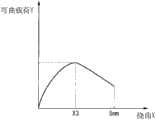
还不存在明确表示弯曲了管状支架时的内腔的保持性与柔软性的、确立的指标。因此,在本发明中,进行了以下悬臂刚性试验。如图3所示,将通过该悬臂刚性试验获得的最大弯曲载荷Y1、使最大弯曲载荷Y1起作用时的挠曲X1、作为最大弯曲载荷Y1与挠曲X1下的恢复弯曲载荷Y2之差的反弹力Z、以及支架的壁厚D1作为表示内腔的保持性、柔软性、内腔的宽度程度的指标。There is no established index that clearly indicates the lumen retention and flexibility when the tubular stent is bent. Therefore, in the present invention, the following cantilever rigidity test was performed. As shown in FIG. 3, the maximum bending load Y1 obtained by this cantilever stiffness test, the deflection X1 when the maximum bending load Y1 is applied, and the difference between the maximum bending load Y1 and the recovery bending load Y2 at the deflection X1 The rebound force Z and the wall thickness D1 of the stent serve as indexes showing the degree of retention, flexibility, and width of the lumen.
在根据上述试验获得的数据中,将最大弯曲载荷Y1除以最大弯曲载荷时的挠曲X1得到的值作为指标A。另外,将反弹力Z除以指标A得到的值的百分率作为指标B。In the data obtained by the above-mentioned test, the value obtained by dividing the maximum bending load Y1 by the deflection X1 at the time of the maximum bending load was used as the index A. In addition, the percentage of the value obtained by dividing the rebound force Z by the index A was used as the index B.
即,能够用(2)式~(4)式表示反弹力Z、指标A及指标B。That is, the rebound force Z, the index A, and the index B can be represented by the expressions (2) to (4).
(公式2)(Formula 2)
Z=Y1-Y2··(2)Z=Y1-Y2··(2)
优选的是,本实施方式的支架1适当地设定上述指标A、指标B及壁厚D1。适当地设定各个指标例如是通过将内部层5的壁厚设定为0.005mm~0.10mm、将外部层4的壁厚设定为0.07mm~0.34mm来实现。It is preferable for the
图4是说明本发明中的悬臂刚性试验的方法的图。另外,在成为测量对象的支架S1中,翼部可有可无。Fig. 4 is a diagram illustrating a method of a cantilever rigidity test in the present invention. In addition, in the stent S1 used as a measurement object, the wing part is optional.
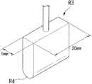
向支架S1的内腔插入具有与该内腔的直径大致相同的直径的圆柱状的芯体R1。插入芯体R1的范围是从支架S1的基端侧到距支架S1的顶端10mm的位置S2。然后,水平配置支架S1,利用夹具R2夹持支承支架S1的与插入芯体R1的范围对应部分的外周面。A cylindrical core R1 having a diameter substantially equal to the diameter of the lumen is inserted into the lumen of the stent S1. The range where the core R1 is inserted is from the base end side of the stent S1 to a
接着,以配件R3的中心在从位置S 2向顶端侧离开5mm的位置S3处从上方抵接支架S1的外周面的方式,装配配件R3。然后,利用未图示的测量装置并行测量按下了配件R3时的挠曲X和配件R3自支架S1受到的反作用力(弯曲载荷Y),同时以每分钟5mm的速度将配件R3向铅垂下方按下5mm。另外,在将配件R3按下了5mm之后,以相同速度使配件R3向反方向返回,测量自支架S1受到的力。Next, the center of the accessory R3 abuts against the outer peripheral surface of the bracket S1 from above at a position S3 that is 5 mm away from the position S2 toward the tip side, and the accessory R3 is assembled. Then, the deflection X when the fitting R3 is pushed down and the reaction force (bending load Y) received by the fitting R3 from the bracket S1 are measured in parallel with a measuring device not shown, and the fitting R3 is vertically lowered at a rate of 5 mm per minute. side press 5mm. In addition, after the attachment R3 was pushed down by 5 mm, the attachment R3 was returned in the opposite direction at the same speed, and the force received from the stand S1 was measured.
如图5所示,配件R3的形状形成为宽20mm、厚5mm的板状。配件R3相对于支架S1的接触面R4形成为曲率半径为2.5mm的曲面状,以使得对支架S1的弯曲载荷不会集中于一点。As shown in FIG. 5 , the fitting R3 is formed into a plate shape with a width of 20 mm and a thickness of 5 mm. The contact surface R4 of the fitting R3 with the bracket S1 is formed into a curved surface with a radius of curvature of 2.5 mm so that the bending load on the bracket S1 does not concentrate at one point.
在图6中示出利用本实施方式的支架1进行悬臂刚性试验的结果的一个例子。图6的纵轴表示弯曲载荷Y,横轴表示挠曲X。随着配件R3的按下量增大,支架1的挠曲X也变大,在某一挠曲X1下支架1达到最大弯曲载荷Y1。这之后即使增大挠曲X,弯曲载荷Y也减少。虽然支架1随之弯曲,但在最大弯曲载荷Y1比预定大、并且未设有用于保持内腔的加强层等特别构件的情况下,支架折断。FIG. 6 shows an example of the results of a cantilever rigidity test using the
如果最大弯曲载荷Y1较小,则支架易于弯曲,如果最大弯曲载荷Y1较大,则支架难以弯曲(柔软性较低)。但是,最大弯曲载荷Y1较小并且表示最大弯曲载荷Y1时的挠曲X1小于一定值的情况表现出在进行弯曲直至挠曲X成为5mm的期间支架折断(弯曲)、不能够保持内腔。另一方面,即使最大弯曲载荷Y1较小而表示最大弯曲载荷Y1时的挠曲X1大于一定值的情况表现出在使支架弯曲直至挠曲X成为5mm的期间支架不会折断而保持内腔。If the maximum bending load Y1 is small, the stent is easy to bend, and if the maximum bending load Y1 is large, the stent is difficult to bend (low flexibility). However, when the maximum bending load Y1 is small and the deflection X1 at the maximum bending load Y1 is smaller than a certain value, the stent breaks (bends) during bending until the deflection X reaches 5 mm, and the lumen cannot be held. On the other hand, even if the maximum bending load Y1 is small, the case where the deflection X1 at the maximum bending load Y1 is greater than a certain value means that the stent is kept without breaking while the stent is bent until the deflection X becomes 5 mm.
另外,如果最大弯曲载荷Y1与表示最大弯曲载荷Y1时的挠曲X1下的恢复弯曲载荷之差小,则表示反弹力较大,即表示欲恢复到原来形状的力大。In addition, if the difference between the maximum bending load Y1 and the recovery bending load under the deflection X1 at the time of the maximum bending load Y1 is small, the rebound force is large, that is, the force to return to the original shape is large.
指标A大于一定值的情况表示难以弯曲(较硬)、弯曲时的内腔保持性较弱。另外,指标A小于一定值的情况表示易于弯曲(柔软)、但弯曲时的内腔保持性较弱。When the index A is greater than a certain value, it is difficult to bend (stiff), and the lumen retention during bending is weak. In addition, when the index A is less than a certain value, it means that it is easy to bend (soft), but the lumen retainability at the time of bending is weak.
另外,壁厚D1大于一定值的情况表示在某一标称尺寸处内径较小。另外,壁厚D1小于一定值的情况表示在某一标称尺寸处内径较大。In addition, the case where the wall thickness D1 is larger than a certain value indicates that the inner diameter is smaller at a certain nominal size. In addition, the case where the wall thickness D1 is smaller than a certain value means that the inner diameter is larger at a certain nominal size.
另外,如果指标B大则表示反弹力大,指标B较小的情况表示易于塑性变形。作为支架,优选的是指标B较小,然而,若考虑实施的手术,则操作性降低。In addition, when the index B is large, it means that the rebound force is large, and when the index B is small, it means that plastic deformation is easy. As a stent, it is preferable that the index B is small, however, considering the operation to be performed, the operability decreases.
即,支架所要求的事项为,指标A、指标B、壁厚D1表示出适度的值。That is, what is required for the stent is that the index A, the index B, and the wall thickness D1 show moderate values.
另外,如图3所示,支架所要求的最大弯曲载荷Y1的上限值、最大弯曲载荷Y1时的挠曲X1的下限值、以及恢复弯曲载荷Y2根据支架外径的标称尺寸K(参照图1)而不同。In addition, as shown in Figure 3, the upper limit value of the maximum bending load Y1 required by the bracket, the lower limit value of the deflection X1 at the maximum bending load Y1, and the recovery bending load Y2 are based on the nominal size K of the bracket outer diameter ( Refer to Figure 1) and differ.
本实施方式的支架1是其标称尺寸K为10Fr,内径为φ2.8mm,外径为φ3.2mm。The
优选的是,指标A小于4N/mm,壁厚D1为0.20mm~0.35mm,指标B的上限值为70%。Preferably, the index A is less than 4N/mm, the wall thickness D1 is 0.20mm-0.35mm, and the upper limit of the index B is 70%.
根据对本实施方式的支架1进行悬臂刚性试验的结果可知,指标A为1.29N/mm,壁厚D1为0.24mm,指标B为56%,支架1能够增大内腔,而且能够充分保持内腔,柔软且反弹力小。According to the results of the cantilever rigidity test on the
另外,同样,根据对改变本实施方式的支架1的材料而形成的支架实施悬臂刚性试验的结果可知,指标A为0.49N/mm,指标B为0.24mm,指标C为50%,支架1能够增大内腔,而且能够充分保持内腔,柔软且反弹力小。In addition, similarly, according to the results of the cantilever rigidity test on the stent formed by changing the material of the
作为比较例,图7中示出利用标称尺寸为10French、但未使用线圈的以往支架进行悬臂刚性试验的结果的一个例子。As a comparative example, FIG. 7 shows an example of the results of a cantilever rigidity test using a conventional stent with a nominal size of 10 French but not using a coil.
可知,在小于2.0mm的某一挠曲X3处,支架折断,在使支架弯曲直至挠曲X成为5mm时,支架的内腔变小。It can be seen that the stent breaks at a certain deflection X3 of less than 2.0 mm, and the lumen of the stent becomes smaller when the stent is bent until the deflection X becomes 5 mm.
另外,示出使用不是线圈的加强层、例如叶片的以往支架进行悬臂刚性试验的结果的一个例子。In addition, an example of the results of a cantilever rigidity test using a reinforcing layer other than a coil, such as a conventional bracket of a blade, is shown.
在使支架弯曲直至成为5mm时,支架的内腔不会变小,未追随于配件R3的按下而是在较低的挠曲X3处出现最大载荷。另外可知,最大弯曲载荷时的挠曲X3下的恢复弯曲载荷也较高。When the stent is bent to 5 mm, the lumen of the stent does not become smaller, and the maximum load occurs at a lower deflection X3 without following the pressing of the fitting R3. In addition, it can be seen that the recovery bending load under the deflection X3 at the time of the maximum bending load is also high.
另外,改变叶片与外层部的材料并制作柔软的支架,再次进行验证。其结果可知,能够大幅度降低最大载荷,但是直至成为5mm,支架的内腔不会变小。另外可知,由于未仅由柔软的树脂构成,因此进行塑性变形。Also, change the material of the blade and the outer layer to make a flexible bracket and verify again. As a result, it was found that the maximum load can be significantly reduced, but the lumen of the stent does not become smaller until it reaches 5 mm. In addition, it can be seen that plastic deformation occurs because it is not composed of only soft resin.
接着,以下以将支架1留置在胆管内的手法为例说明如以上那样构成的支架1的动作。Next, the operation of the
首先,使用者将侧视型的内窥镜从口等自然开口插入患者的体腔内,如图8所示那样使内窥镜E1的顶端前进至十二指肠乳头H1附近。First, the user inserts a side-view endoscope into the patient's body cavity through a natural opening such as a mouth, and advances the tip of the endoscope E1 to the vicinity of the duodenal papilla H1 as shown in FIG. 8 .
接着,使用者从内窥镜E1的未图示的钳子口插入导线E2,一边适当地操作未图示的抬起台,一边使导线E2的顶端朝向十二指肠乳头H1突出。然后,将导线E 2的顶端从十二指肠乳头H1插入胆管H2内。Next, the user inserts the guide wire E2 from the unshown forceps port of the endoscope E1, and protrudes the tip of the guide wire E2 toward the duodenal papilla H1 while appropriately operating the unshown lifting table. Then, insert the tip of the wire E2 from the duodenal papilla H1 into the bile duct H2.
然后,使用者在X射线透视下确认十二指肠乳头H1与胆管H2的狭窄部H3的形状,选择具有各个翼部8~11、16~19张开时的、从翼部8~11的自由端到翼部16~19的自由端之间的长度长于自十二指肠乳头H1到胆管H2的狭窄部H3的长度的支架1。Then, the user confirms the shape of the narrowed part H3 of the duodenal papilla H1 and the bile duct H2 under X-ray fluoroscopy, and selects the free ends from the
接着,使用者一边确认支架1与胆管H2的位置与形状,一边利用从钳子口插入的未图示的支架输送导管沿着导线E2将支架1自顶端(即翼部8~11)侧插入胆管H2内。Next, while confirming the position and shape of the
若支架1的顶端到达胆管H2的狭窄部H3,则翼部8~11被狭窄部H3朝向轴线C1按压,翼部8~11分别容纳于切口部12~15。若支架1进一步插入胆管H2内且翼部8~11穿过狭窄部H3,则如图9所示,翼部8~11的自由端张开,翼部8~11卡定于狭窄部H3。When the distal end of the
此时,由于选择了从翼部8~11的自由端到翼部16~19的自由端之间的长度超过狭窄部H3的长度的支架1,因此翼部16~19也卡定于十二指肠乳头H1。At this time, since the
之后,使用者从患者的体腔内取出内窥镜E1,结束一连串的手法。Thereafter, the user takes out the endoscope E1 from the patient's body cavity, and ends a series of procedures.
如以上说明那样,根据本实施方式的支架1,由于在外部层4与内部层5之间具有线圈3,因此难以沿径向压扁支架1,即使施加有由胆管的弯曲、行进变化等带来的弯曲载荷,也始终能够保持内腔的大小。As described above, according to the
另外,由于未使用叶片,因此能够抑制线材2之间重叠而沿径向变厚,并且能够防止产生线材2之间的摩擦而使支架1难以弯曲。In addition, since the blades are not used, it is possible to suppress overlapping of the
另外,由于外部层4由弯曲弹性率为700MPa以下且肖氏硬度为70D以下、玻璃化转变温度高于-40℃的聚氨酯系弹性体树脂形成,因此能够抑制外部层4变硬,使支架1整体易于弯曲。而且,由于在体内将外部层4加热至大致体温,因此能够使外部层4更柔软。In addition, since the
另外,支架1的各个构件的尺寸及材料设定为,外部层4外径的标称尺寸K为10Fr,悬臂刚性试验中的最大弯曲载荷除以最大弯曲载荷时的挠曲得到的值为0.3N/mm以上,并且支架1的壁厚D1为0.35mm以下。因而,能够使支架1薄壁化,即能够确保较宽的内腔,并且易于弯曲且难以压扁。In addition, the dimensions and materials of each member of the
另外,由于设有翼部8~11、16~19,因此能够将支架1卡定于胆管H2的狭窄部H3,从而能够防止支架1偏离、或脱离。In addition, since the
通过如上述那样构成支架,能够将例如内径(内部层5的内径)为7.2Fr(2.4mm)的支架的外径(外部层4的外径)从以往产品的10.0Fr(3.3mm)细化到8.5Fr(2.8mm)的程度。另外,能够将内径为8.5Fr(2.8mm)的支架的外径从以往产品的11.5Fr~12.0Fr(3.8mm~4.0mm)细化到10.0Fr(3.2mm)的程度。By configuring the stent as described above, for example, the outer diameter (outer diameter of the outer layer 4 ) of the stent whose inner diameter (inner diameter of the inner layer 5 ) is 7.2 Fr (2.4 mm) can be reduced from 10.0 Fr (3.3 mm) of a conventional product. To the extent of 8.5Fr (2.8mm). In addition, the outer diameter of a stent with an inner diameter of 8.5Fr (2.8mm) can be reduced from 11.5Fr to 12.0Fr (3.8mm to 4.0mm) of conventional products to about 10.0Fr (3.2mm).
即,根据本实施方式的支架1,与以往的支架相比,能够提供一种内径相同且外径更细的支架、外径相同且内径更大的支架。That is, according to the
通过设置线圈3,由于不必在支架1中使用较多的造影剂,因此能够减少支架1的物理属性降低的因素。By providing the
另外,在支架1偏离了的情况下、或者在采用了故意将基端部4b插入胆管内的手法(内侧支架)的情况下,能够利用线圈3在X射线透视下确认支架1的基端部4b位置,从而能够使支架1的回收变得容易。In addition, when the
(第2实施方式)(Second embodiment)
接着,说明本发明的第2实施方式。在本实施方式中,对与第1实施方式相同的部位标注相同的附图标记并省略其说明,仅说明不同点。Next, a second embodiment of the present invention will be described. In this embodiment, the same reference numerals are assigned to the same parts as those in the first embodiment, and descriptions thereof will be omitted, and only differences will be described.
如图10所示,本实施方式的支架31取代第1实施方式的支架1的线圈3而具有线圈33,该线圈33包括绕轴线C1以大致紧密成卷的方式卷绕线圈3的轴线C1上的预定位置的线材2而成的标记线圈部32、和以与第1实施方式的线圈3的线材2相同的间距P1卷绕而成的普通卷绕线圈部34、35。As shown in FIG. 10 , instead of the
另外,此处所说的“大致紧密成卷”是指以比线材外径的1倍大且7倍以下的一定值的间距卷绕线材。例如,在使用外径为0.11mm的线材2的本实施方式中,在标记线圈部32中,相邻的线材2之间的间隙为0.01mm~0.08mm,线材2的间距P2为0.12mm~0.19mm。此时,线材2的间距P2为线材2外径的大致1.1倍~1.7倍。另外,为了便于说明,该间隙在附图中未示出。In addition, "substantially densely coiled" as used herein means that the wire rod is wound at a constant pitch that is greater than 1 time and 7 times or less the outer diameter of the wire rod. For example, in this
通过如此设置间隙,在标记线圈部32中,在相邻的线材2之间的间隙部分也能够使外部层4与内部层5相互连接、使外部层4与内部层5难以相互分离。By providing the gap in this way, the
另外,若标记线圈部32的尺寸超出上述范围,则不会产生由疏部(即普通卷绕线圈部)的线圈间距与密部(即标记线圈部)的线圈间距带来的X射线不透过度之差。In addition, if the size of the
另外,优选的是,该标记线圈部32沿轴线C1的长度为9mm以下。这是为了顺畅地通过内窥镜出口的钳子抬起台。另外,在线圈的自由度固定在某一范围内的情况下,在标记线圈部32沿轴线C1的长度为9mm以上的情况下,有可能在钳子抬起台抬起了的状态下难以通过钳子抬起台。In addition, it is preferable that the length of the
标记线圈部32的顶端在轴线C1方向上配置为处于与切口部12的基端相同的位置。The leading end of the
线圈33的除标记线圈部32以外的部分由以与第1实施方式的线圈3的线材2相同的间距P1(0.41mm左右)卷绕而成的普通卷绕线圈部34、35构成。Parts of the
优选的是,普通卷绕线圈部34、35中的线材2的间距P1是标记线圈部32的线材2的间距P2的2倍~20倍的间距。It is preferable that the pitch P1 of the
若间距P1小于间距P2的2倍,则在X射线透视下,难以区分标记线圈部32与普通卷绕线圈部34、35。另外,若间距P1比间距P2的20倍大,则在弯曲了支架31时不能够保持内腔大小。另外,树脂不会进入以间距P2卷绕的线材2的间隙中,导致该部分鼓起。If the pitch P1 is less than twice the pitch P2, it is difficult to distinguish the
普通卷绕线圈部34与标记线圈部32的顶端相连接,普通卷绕线圈部35与标记线圈部32的基端相连接。而且,由标记线圈部32、普通卷绕线圈部34及普通卷绕线圈部35构成了线圈33。The normal
在将如此构成的支架31留置在胆管H2中时,在X射线透视下,由于标记线圈部32的X射线不透过度(X射线遮蔽度)与普通卷绕线圈部34及普通卷绕线圈部35的X射线不透过度在可视程度上不同,因此能够确定标记线圈部32与普通卷绕线圈部34之间的交界、以及标记线圈部32与普通卷绕线圈部35之间的交界。When the
如图11所示,使用者在X射线透视下一边确定胆管H2的形状与线圈33的标记线圈部32的位置、一边将支架31插入胆管H2内。而且,若在标记线圈部32穿过了狭窄部H3时停止插入支架31,则翼部8~11扩张而卡定于狭窄部H3。As shown in FIG. 11 , the user inserts the
在上述日本特开2006-87712号公报所记载的支架中,在顶端部与基端部分别形成有以在自然状态下张开的方式形成的翼部。在将该支架的顶端部插入胆管内的狭窄部中时,形成于顶端部的翼部被狭窄部按压并成为闭合了的状态。而且,若该翼部通过胆管的狭窄部,则闭合的翼部张开而翼部卡定于胆管,限制支架向十二指肠侧移动。In the stent described in Japanese Patent Application Laid-Open No. 2006-87712, wing portions formed so as to expand in a natural state are formed at the distal end portion and the proximal end portion, respectively. When the distal end portion of the stent is inserted into the narrowed portion of the bile duct, the wing portions formed on the distal end portion are pressed by the narrowed portion and closed. Then, when the wings pass through the narrowed part of the bile duct, the closed wings are opened and the wings are locked to the bile duct to restrict the movement of the stent toward the duodenum.
但是,在X射线透视下,由于难以目视确认支架的翼部,因此难以获知翼部是否张开、翼部是否卡定于胆管。因此,若支架插入胆管中的深度较浅,则有时翼部未张开而支架向十二指肠侧脱离。However, under X-ray fluoroscopy, since it is difficult to visually confirm the wings of the stent, it is difficult to know whether the wings are opened and whether the wings are locked to the bile duct. Therefore, if the depth of insertion of the stent into the bile duct is shallow, the wings may not expand and the stent may detach toward the duodenum.
如以上说明那样,根据本实施方式的支架31,与支架1相同,能够抑制壁厚而维持易弯曲度、并且即使施加由胆管的弯曲、行进变化等带来的弯曲载荷也始终难以压扁。As described above, according to the
而且,在标记线圈部32与普通卷绕线圈部34、35中,卷绕线材2的间距不同。因此,在向线圈33照射了一定强度的X射线时,在标记线圈部32的X射线不透过度与普通卷绕线圈部34、35的X射线不透过度之间产生差异。通过该强度之差,能够在X射线透视下目视确认支架31中的翼部8~11顶端(自由端)的位置。Furthermore, the pitch of the winding
由于即使未在翼部8~11中使用较多的造影剂也能够目视确认翼部8~11顶端的位置,因此能够提高翼部8的强度。另外,由此能够减少翼部8的物理属性降低的因素。Since the positions of the tips of the
由于标记线圈部32设置在支架31的轴线C1方向的中间部,因此能够更明确地确认到支架31整体。这对在留置多根支架时自第2根以后的留置是有用的。Since the
另外,在支架31自顶端部4a侧在胆管H2的狭窄部H3内行进时,翼部8~11被按压卡定于狭窄部H3的内壁而自由端向外部层4的外周面侧移动。此时,在X射线透视下,使用者能够目视确认生物体的胆管H2的形状与支架31的标记线圈部32的位置。In addition, when the
另外,由于位于翼部8~11附近的X射线标记是标记线圈部32,因此即使针对局部弯曲也能够柔软地弯曲。In addition, since the X-ray marker located near the
而且,使用者通过使支架31的标记线圈部32穿过胆管H2的狭窄部H3而进入胆管H2内,来解除狭窄部H3对翼部8~11自由端的按压。此时,由于翼部8~11的自由端侧利用自身的弹性向外部层4的径向外侧张开,因此支架31在翼部8~11的作用下卡定于胆管H2的狭窄部H3里侧。Then, the user releases the pressure of the free ends of the
即,使用者通过使在X射线透视下能够确定的标记线圈部32穿过胆管H2的狭窄部H3而进入胆管H2内,能够使翼部8~11可靠地卡定于胆管H2的狭窄部H3里侧。That is, the user can securely lock the
另外,如图12所示,也可以以使标记线圈部32的基端位于在轴线C1方向上与切口部12的顶端相同的位置的方式配置标记线圈部32。In addition, as shown in FIG. 12 , the
另外,如图13所示的支架41那样,也可以在线圈33的顶端部及基端部这两者上设置与上述标记线圈部32相同地绕轴线C1以大致紧密成卷的方式卷绕线材2而成的标记线圈部42及标记线圈部43。In addition, like the holder 41 shown in FIG. 13 , it is also possible to provide both the distal end portion and the base end portion of the
通过如此构成支架41,能够利用标记线圈部42、43在X射线透视下更可靠地目视确认线圈33的顶端部及基端部的位置。By configuring the holder 41 in this way, the positions of the distal end portion and the proximal end portion of the
通过设置标记线圈部43,能够向支架41的顶端部4a侧高效地传递在插入时作用于基端部4b侧的力量。作为其理由可认为是,标记线圈部43耐轴线C1方向的压缩、以及与比较疏松地卷绕线材而成的疏部(普通卷绕线圈部)相比比较密地卷绕线材而成的密部(标记线圈部)的线材2之间的距离较小,因此树脂难以充分地填充于线材2之间的间隙内。以下进一步说明上述后者的理由。与疏部相比,密部的外径值稍微变大。这意味着向顶端部4a侧传递来自基端部4b侧的力量时的管截面面积较大。因此,通过在直接承受力量的一侧即基端部4b上设置相对较密地卷绕线材而成的标记线圈部43,能够容易地插入支架41。By providing the
(第3实施方式)(third embodiment)
接着,说明本发明的第3实施方式,但对与第1及第2实施方式相同的部位标注相同的附图标记并省略其说明,仅说明不同点。Next, a third embodiment of the present invention will be described, but the same parts as those in the first and second embodiments will be assigned the same reference numerals and their description will be omitted, and only the different points will be described.
如图14所示,本实施方式的支架51取代第2实施方式的变形例的支架41的线圈33而具有线圈53。As shown in FIG. 14 , the
线圈53包括普通卷绕线圈部35、分别设于线圈53的两端的标记线圈部42、43、设于普通卷绕线圈部35与标记线圈部42之间的疏卷线圈部54、以及设于普通卷绕线圈部35与标记线圈部43之间的疏卷线圈部55。The
在本实施方式中,优选的是,普通卷绕线圈部35中的线材2的间距P1是标记线圈部42、43的线材2间距P2的2倍~20倍,疏卷线圈部54、55中的线材2间距P3是普通卷绕线圈部35的线材2间距P1的1.1倍~5倍。In this embodiment, it is preferable that the pitch P1 of the
由于疏卷线圈部54、55的各个线材2间距是普通卷绕线圈部35的线材2间距的1.1倍以上,因此能够在X射线透视下目视确认疏卷线圈部54与普通卷绕线圈部35之间的交界以及疏卷线圈部55与普通卷绕线圈部35之间的交界。另外,由于疏卷线圈部54的线材2间距是标记线圈部42的线材2间距的2倍以上,且疏卷线圈部55的线材2间距是标记线圈部43的线材2间距的2倍以上,因此也能够在X射线透视下目视确认疏卷线圈部54与标记线圈部42之间的交界以及疏卷线圈部55与标记线圈部43之间的交界。Since the spacing between the
疏卷线圈部54及疏卷线圈部55分别设置于在沿着轴线C1的方向上与翼部8~11及翼部16~19大致对应的范围内。The sparsely wound
根据如此构成的本实施方式的支架51,与各个实施方式的支架相同,能够抑制壁厚而维持易弯曲度,同时能够难以压扁。According to the
而且,通过在X射线透视下目视确认相邻的线圈之间的交界,能够确定与翼部8~11及翼部16~19的各个固定端及自由端对应的位置。Furthermore, by visually confirming the boundaries between adjacent coils under X-ray fluoroscopy, the positions corresponding to the respective fixed ends and free ends of the
(第4实施方式)(fourth embodiment)
接着,说明本发明的第4实施方式,但对与第1~第3实施方式相同的部位标注相同的附图标记并省略其说明,仅说明不同点。Next, the fourth embodiment of the present invention will be described, but the same parts as those in the first to third embodiments will be given the same reference numerals and their description will be omitted, and only the different points will be described.
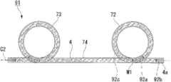
如图15所示,本实施方式的支架61取代第3实施方式的支架51的线圈53而在轴线C1上以错开位置的方式设置有标记线圈(线圈)64、普通卷绕线圈(线圈)65、标记线圈(线圈)66。As shown in FIG. 15 , in the
标记线圈64、66是以与上述标记线圈部32相同的间距P2绕轴线C1以大致紧密成卷的方式卷绕线材2而形成的。另外,普通卷绕线圈65是以与上述普通卷绕线圈部35相同的间距P1绕轴线C1卷绕线材2而形成的。The marker coils 64 and 66 are formed by winding the
普通卷绕线圈65与标记线圈64利用连接部67相连接,普通卷绕线圈65与标记线圈66利用连接部68相连接。The normal winding
如图15及图16所示,连接部67由与轴线C1平行的一组线材2形成。线材2配置为与轴线C1呈线对称,各个线材2的一端与标记线圈64相连接并且另一端与普通卷绕线圈65相连接。线材2与标记线圈64、普通卷绕线圈65之间的连接方法能够采用锡焊、点焊、或使用T字型的接合构件来连接等公知的各种方法。As shown in FIGS. 15 and 16 , the connecting
另外,能够适当地设定连接部67所使用的线材2的根数、位置。Moreover, the number and position of the
与连接部67相同,连接部68由一组线材2形成,各个线材2的一端与标记线圈66相连接并且另一端与普通卷绕线圈65相连接。Like the connecting
根据如此构成的本实施方式的支架61,能够抑制壁厚而维持易弯曲度,并且即使施加由胆管的弯曲、行进变化等带来的弯曲载荷也始终难以压扁。According to the
而且,由于连接部67、68的线材2配置为沿着轴线C1延伸,因此能够向基端部4b高效地传递在顶端部4a上沿轴线C1方向作用的力,能够向顶端部4a高效地传递在基端部4b上沿轴线C1方向作用的力。通过如此传递力,在利用公知的支架推动件将支架61留置在胆管H2内时,能够利用支架推动件向顶端部4a传递支架61的基端部4b所受到的力,从而能够更容易地将支架61插入胆管H2的狭窄部H3内。Furthermore, since the
(第5实施方式)(fifth embodiment)
接着,说明本发明的第5实施方式,但对与第1~第4实施方式相同的部位标注相同的附图标记并省略其说明,仅说明不同点。Next, a fifth embodiment of the present invention will be described, but the same parts as those in the first to fourth embodiments will be assigned the same reference numerals and their description will be omitted, and only the different points will be described.
如图17所示,在本实施方式的支架71上未设有翼部,在顶端部4a及基端部4b上分别具有以形成与轴线C2平行的环面的方式旋转1周的、形成为所谓的猪尾状的弯曲部72、73。另外,支架71的被弯曲部72与弯曲部73夹住的部分、即分别与弯曲部72和弯曲部73相邻的部分成为主体部74。As shown in FIG. 17 , the
在外部层4内设置有后述的线圈75,而且在该线圈75内设置有上述内部层5(未图示)。A
在该线圈75中,在从弯曲部72与主体部74之间的交界M1至顶端部4a侧、以及从弯曲部73与主体部74之间的交界M2至基端部4b侧,分别形成有以与上述标记线圈部32相同的间距P2绕轴线C2以大致紧密成卷的方式卷绕线材2而成的标记线圈部75a及标记线圈部75b。而且,在被标记线圈部75a、75b夹住的部分,形成有以与上述普通卷绕线圈部35相同的间距P1绕轴线C2卷绕线材2而成的普通卷绕线圈部75c。In this
根据如此构成的本实施方式的支架71,在X射线透视下,能够确定交界M1、M2的位置、以及顶端部4a与基端部4b的位置。另外,利用通过使线圈间距不同而产生的色调的浓淡,在外观上也能够确定交界。According to the
另外,如图18的支架81所示,也可以取代上述实施方式的支架71的标记线圈部75a及标记线圈部75b而具有以与上述普通卷绕线圈部35相同的间距P1绕轴线C2卷绕线材2而成的普通卷绕线圈部82a及普通卷绕线圈部82b,取代普通卷绕线圈部75c而具有以与上述标记线圈部32相同的间距P2绕轴线C2以大致紧密成卷的方式卷绕线材2而成的标记线圈部82c。In addition, as shown in the
另外,如图19所示的支架91那样,也可以取代上述实施方式的支架71的标记线圈部75a而仅在距交界M1为预定距离处和距顶端部4a为预定距离处设置以与上述标记线圈部32相同的间距P2绕轴线C2以大致紧密成卷的方式卷绕线材2而成的标记线圈部92a、92b,在标记线圈部92a、92b之间设置以与上述普通卷绕线圈部35相同的间距P1绕轴线C2卷绕线材2而成的普通卷绕线圈部92c。In addition, like the
另外,也可以与顶端部4a侧相同地构成支架91的基端部4b侧。In addition, the
另外,如图20所示的支架101那样,也可以取代上述变形例的支架91的标记线圈部92b与普通卷绕线圈部92c而设置以与上述疏卷线圈部54相同的间距P3绕轴线C2卷绕线材2而成的疏卷线圈部102a。In addition, as in the
另外,也可以与顶端部4a侧相同地构成支架101的基端部4b侧。In addition, the
以上,参照附图详细说明了本发明的第1实施方式~第5实施方式,但是具体结构并不限于该实施方式,也包含不脱离本发明的主旨的范围内的结构的变更等。Above, the first to fifth embodiments of the present invention have been described in detail with reference to the drawings, but the specific configurations are not limited to the embodiments, and structural changes within the scope of the present invention are also included.
例如,在上述第1实施方式~第5实施方式中,作为线材2,使用了金属制且剖面形成为圆形的线材。但是,作为线材,也可以使用剖面为矩形的线材,并将其卷绕为螺旋状而形成平线线圈。而且,也可以使用捻线作为线材。For example, in the above-mentioned first to fifth embodiments, as the
另外,在上述第1实施方式~第5实施方式中,利用单条绕的线材2构成了线圈3,但是也可以利用使多个线材沿径向排列而呈螺旋状卷绕而成的、所谓的多条绕的线材来构成线圈。In addition, in the above-mentioned first to fifth embodiments, the
另外,在上述第2实施方式~第5实施方式中,以大致紧密成卷的方式卷绕线材2而形成了标记线圈。但是,也可以在标记线圈的线材2之间不设置间隙,而是以紧密成卷的方式卷绕线材2。Moreover, in the said 2nd - 5th embodiment, the
而且,在上述第2实施方式~第5实施方式中,为了目视确认相邻线圈的连接部分位置而改变了卷绕线材2的间距,但是也可以在使间距恒定的状态下改变线材的直径。In addition, in the above-mentioned second to fifth embodiments, the pitch of the winding
产业上的可利用性Industrial availability
根据本发明的医疗用支架,能够维持易弯曲且反弹性较小这样的特性,同时在弯曲时难以压扁内腔。另外,能够在不降低柔软性、反弹性等支架的物理属性的情况下提高造影性。According to the stent for medical use of the present invention, while maintaining the characteristics of being easy to bend and having low resilience, it is difficult to crush the lumen during bending. In addition, the contrast property can be improved without reducing the physical properties of the stent such as flexibility and resilience.
附图标记说明Explanation of reference signs
1、31、41、51、61、71、81、91、101支架(医疗用支架)1, 31, 41, 51, 61, 71, 81, 91, 101 stents (medical stents)
2线材2 wire
3、53、63、75、82线圈3, 53, 63, 75, 82 coils
4外部层4 outer layers
5内部层5 inner layers
8~11、16~19翼部(卡定构件)8~11, 16~19 wings (locking member)
32、42、43、75a、75b、82c、92a、92b 标记线圈部32, 42, 43, 75a, 75b, 82c, 92a, 92b mark the coil part
34、35、82a、82b、75c、92c 普通卷绕线圈部34, 35, 82a, 82b, 75c, 92c Ordinary winding coil part
54、55疏卷线圈部54, 55 Sparse Coil Department
64、66标记线圈(线圈)64, 66 mark coil (coil)
65普通卷绕线圈(线圈)65 Ordinary wound coils (coils)
72、73弯曲部72, 73 bending part
C1、C2轴线C1, C2 axis
D1壁厚D1 wall thickness
Claims (10)
Applications Claiming Priority (3)
| Application Number | Priority Date | Filing Date | Title |
|---|---|---|---|
| JP2010073817 | 2010-03-26 | ||
| JP2010-073817 | 2010-03-26 | ||
| PCT/JP2010/070197WO2011118081A1 (en) | 2010-03-26 | 2010-11-12 | Medical stent |
Publications (2)
| Publication Number | Publication Date |
|---|---|
| CN102655824Atrue CN102655824A (en) | 2012-09-05 |
| CN102655824B CN102655824B (en) | 2014-10-29 |
Family
ID=44672665
Family Applications (1)
| Application Number | Title | Priority Date | Filing Date |
|---|---|---|---|
| CN201080056531.2AActiveCN102655824B (en) | 2010-03-26 | 2010-11-12 | Medical stent |
Country Status (5)
| Country | Link |
|---|---|
| US (2) | US8632606B2 (en) |
| EP (2) | EP2803339B1 (en) |
| JP (1) | JP4981994B2 (en) |
| CN (1) | CN102655824B (en) |
| WO (1) | WO2011118081A1 (en) |
Cited By (6)
| Publication number | Priority date | Publication date | Assignee | Title |
|---|---|---|---|---|
| CN104188741A (en)* | 2014-08-29 | 2014-12-10 | 东莞颠覆产品设计有限公司 | Degradable connector implanted in body |
| CN104507422A (en)* | 2013-03-07 | 2015-04-08 | 奥林巴斯医疗株式会社 | Medical stent |
| CN105769399A (en)* | 2014-12-23 | 2016-07-20 | 刘凯 | Pancreatic duct stent capable of being taken out easily |
| CN109125893A (en)* | 2013-02-28 | 2019-01-04 | 波士顿科学国际有限公司 | Medical devices used along the biliary and/or pancreatic ducts |
| CN113056243A (en)* | 2018-11-22 | 2021-06-29 | 奥林巴斯株式会社 | Medical stent and stent delivery device |
| CN113633433A (en)* | 2021-10-15 | 2021-11-12 | 微创神通医疗科技(上海)有限公司 | Vascular implant |
Families Citing this family (25)
| Publication number | Priority date | Publication date | Assignee | Title |
|---|---|---|---|---|
| US9387312B2 (en) | 2008-09-15 | 2016-07-12 | Brightwater Medical, Inc. | Convertible nephroureteral catheter |
| US20130158673A1 (en)* | 2011-12-15 | 2013-06-20 | Cook Medical Technologies Llc | Anti-Leakage Prosthesis |
| KR101382524B1 (en)* | 2012-02-27 | 2014-04-07 | 국립암센터 | Double structure stent of projection type |
| WO2014014748A1 (en)* | 2012-07-20 | 2014-01-23 | Cook Medical Technologies Llc | Anti -migration biliary stent |
| EP2749310A1 (en) | 2012-12-28 | 2014-07-02 | Cook Medical Technologies LLC | Ureteral endoluminal device |
| EP3494934B1 (en) | 2013-01-23 | 2022-12-21 | Cook Medical Technologies LLC | Stent with positioning arms |
| WO2014164308A1 (en)* | 2013-03-13 | 2014-10-09 | Boston Scientific Scimed, Inc. | Pancreatic stent drainage system |
| JP2016518162A (en)* | 2013-03-15 | 2016-06-23 | ボストン サイエンティフィック サイムド,インコーポレイテッドBoston Scientific Scimed,Inc. | Anti-migration stent coating |
| JP6037946B2 (en) | 2013-06-10 | 2016-12-07 | オリンパス株式会社 | Stent placement device |
| JP5408682B1 (en)* | 2013-06-28 | 2014-02-05 | ガデリウス・メディカル株式会社 | Stent kit |
| EP3936088A1 (en) | 2014-08-12 | 2022-01-12 | Merit Medical Systems, Inc. | Systems and methods for coupling and decoupling a catheter |
| WO2016100789A1 (en)* | 2014-12-19 | 2016-06-23 | Boston Scientific Scimed, Inc. | Stent with anti-migration features |
| WO2018012387A1 (en)* | 2016-07-12 | 2018-01-18 | 株式会社パイオラックスメディカルデバイス | Covered stent |
| JP7241405B2 (en)* | 2016-11-29 | 2023-03-17 | ファウンドリー イノベーション アンド リサーチ 1,リミテッド | Wireless resonant circuit and variable inductance vascular implant for monitoring vascular and fluid status in patients, and systems and methods utilizing same |
| CN108236751B (en)* | 2016-12-26 | 2025-03-11 | 上海英诺伟医疗器械股份有限公司 | A double-layer drainage tube |
| EP3585318A4 (en)* | 2017-02-21 | 2021-01-20 | Merit Medical Systems, Inc. | Systems and methods for coupling and decoupling a catheter |
| WO2018230435A1 (en)* | 2017-06-13 | 2018-12-20 | 株式会社カネカ | Indwelling tube in living body |
| KR102149135B1 (en)* | 2018-01-17 | 2020-08-31 | 서울대학교병원 | Stent for connection between dissimilar organs with pigtail structute |
| EP3741331A1 (en)* | 2019-05-24 | 2020-11-25 | Seoul National University Hospital | Stent for connecting dissimilar organs with pigtail structure |
| EP3998019B1 (en)* | 2019-07-10 | 2025-09-03 | Kyoto Prefectural Public University Corporation | Medical image guidance marker |
| US12226327B2 (en) | 2020-04-15 | 2025-02-18 | Merit Medical Systems, Inc. | Systems and methods for coupling and decoupling a catheter |
| US11992625B2 (en)* | 2020-07-07 | 2024-05-28 | Covidien Lp | Catheter including variable density structural support member |
| US12168102B2 (en) | 2020-07-07 | 2024-12-17 | Covidien Lp | Catheter including surface-treated structural support member |
| EP3991945A1 (en)* | 2020-10-30 | 2022-05-04 | Fundació Eurecat | 3d printing device and 3d printing method |
| US20220287818A1 (en)* | 2021-03-15 | 2022-09-15 | The Corporation Of Mercer University | Stents and methods of making and using the same |
Citations (10)
| Publication number | Priority date | Publication date | Assignee | Title |
|---|---|---|---|---|
| US5282860A (en)* | 1991-10-16 | 1994-02-01 | Olympus Optical Co., Ltd. | Stent tube for medical use |
| US5514176A (en)* | 1995-01-20 | 1996-05-07 | Vance Products Inc. | Pull apart coil stent |
| WO1999032051A1 (en)* | 1997-12-22 | 1999-07-01 | Impra, Inc. | Supported graft and methods of making same |
| WO2000007524A1 (en)* | 1998-08-05 | 2000-02-17 | Advanced Cardiovascular Systems, Inc. | Intra-luminal device for treatment of body cavities and lumens and method of use |
| CN1350471A (en)* | 1999-05-11 | 2002-05-22 | 钟渊化学工业株式会社 | Balloon catheter |
| JP2002355316A (en)* | 2001-03-30 | 2002-12-10 | Terumo Corp | Stent cover and stent |
| EP1275352A2 (en)* | 1996-09-20 | 2003-01-15 | Converge Medical, Inc. | Radially expanding prostheses and systems for their deployment |
| US20040087886A1 (en)* | 2002-10-30 | 2004-05-06 | Scimed Life Systems, Inc. | Linearly expandable ureteral stent |
| US20040230119A1 (en)* | 2003-05-15 | 2004-11-18 | Brustad John R. | Echogenic stent |
| US20080051911A1 (en)* | 2006-08-23 | 2008-02-28 | Wilson-Cook Medical Inc. | Stent with antimicrobial drainage lumen surface |
Family Cites Families (10)
| Publication number | Priority date | Publication date | Assignee | Title |
|---|---|---|---|---|
| JP3619527B2 (en) | 1991-10-16 | 2005-02-09 | オリンパス株式会社 | In-vivo indwelling tube |
| JP3507503B2 (en) | 1995-03-10 | 2004-03-15 | インプラ・インコーポレーテッド | Sealable stent for body cavity, method for producing the same, and method for introducing the same into body cavity |
| US6312457B1 (en)* | 1999-04-01 | 2001-11-06 | Boston Scientific Corporation | Intraluminal lining |
| US7169187B2 (en) | 1999-12-22 | 2007-01-30 | Ethicon, Inc. | Biodegradable stent |
| US20030040803A1 (en) | 2001-08-23 | 2003-02-27 | Rioux Robert F. | Maintaining an open passageway through a body lumen |
| JP2004147700A (en) | 2002-10-28 | 2004-05-27 | Sumitomo Bakelite Co Ltd | Catheter |
| JP4901087B2 (en) | 2004-09-24 | 2012-03-21 | オリンパス株式会社 | Stent introduction member, stent delivery catheter, and endoscope treatment system |
| WO2006071707A1 (en)* | 2004-12-23 | 2006-07-06 | Wilson-Cook Medical Inc. | Inflatable biliary stent |
| DE202005001416U1 (en)* | 2005-01-28 | 2005-03-31 | Urovision Ges Fuer Medizinisch | stent |
| US7789915B2 (en)* | 2005-08-31 | 2010-09-07 | Vance Products Incorporated | Stent for implantation |
- 2010
- 2010-11-12EPEP14172081.3Apatent/EP2803339B1/ennot_activeNot-in-force
- 2010-11-12CNCN201080056531.2Apatent/CN102655824B/enactiveActive
- 2010-11-12WOPCT/JP2010/070197patent/WO2011118081A1/enactiveApplication Filing
- 2010-11-12EPEP10848473.4Apatent/EP2489334B1/enactiveActive
- 2010-11-12JPJP2011536679Apatent/JP4981994B2/enactiveActive
- 2011
- 2011-09-26USUS13/245,157patent/US8632606B2/enactiveActive
- 2013
- 2013-12-23USUS14/138,772patent/US9192493B2/enactiveActive
Patent Citations (10)
| Publication number | Priority date | Publication date | Assignee | Title |
|---|---|---|---|---|
| US5282860A (en)* | 1991-10-16 | 1994-02-01 | Olympus Optical Co., Ltd. | Stent tube for medical use |
| US5514176A (en)* | 1995-01-20 | 1996-05-07 | Vance Products Inc. | Pull apart coil stent |
| EP1275352A2 (en)* | 1996-09-20 | 2003-01-15 | Converge Medical, Inc. | Radially expanding prostheses and systems for their deployment |
| WO1999032051A1 (en)* | 1997-12-22 | 1999-07-01 | Impra, Inc. | Supported graft and methods of making same |
| WO2000007524A1 (en)* | 1998-08-05 | 2000-02-17 | Advanced Cardiovascular Systems, Inc. | Intra-luminal device for treatment of body cavities and lumens and method of use |
| CN1350471A (en)* | 1999-05-11 | 2002-05-22 | 钟渊化学工业株式会社 | Balloon catheter |
| JP2002355316A (en)* | 2001-03-30 | 2002-12-10 | Terumo Corp | Stent cover and stent |
| US20040087886A1 (en)* | 2002-10-30 | 2004-05-06 | Scimed Life Systems, Inc. | Linearly expandable ureteral stent |
| US20040230119A1 (en)* | 2003-05-15 | 2004-11-18 | Brustad John R. | Echogenic stent |
| US20080051911A1 (en)* | 2006-08-23 | 2008-02-28 | Wilson-Cook Medical Inc. | Stent with antimicrobial drainage lumen surface |
Non-Patent Citations (1)
| Title |
|---|
| 孙酣经等: "《化工新材料及应用手册》", 1 November 2002, article "有机氟材料及制品", pages: 96* |
Cited By (7)
| Publication number | Priority date | Publication date | Assignee | Title |
|---|---|---|---|---|
| CN109125893A (en)* | 2013-02-28 | 2019-01-04 | 波士顿科学国际有限公司 | Medical devices used along the biliary and/or pancreatic ducts |
| CN104507422A (en)* | 2013-03-07 | 2015-04-08 | 奥林巴斯医疗株式会社 | Medical stent |
| CN104188741A (en)* | 2014-08-29 | 2014-12-10 | 东莞颠覆产品设计有限公司 | Degradable connector implanted in body |
| CN105769399A (en)* | 2014-12-23 | 2016-07-20 | 刘凯 | Pancreatic duct stent capable of being taken out easily |
| CN113056243A (en)* | 2018-11-22 | 2021-06-29 | 奥林巴斯株式会社 | Medical stent and stent delivery device |
| CN113056243B (en)* | 2018-11-22 | 2024-06-04 | 奥林巴斯株式会社 | Medical stents and stent delivery devices |
| CN113633433A (en)* | 2021-10-15 | 2021-11-12 | 微创神通医疗科技(上海)有限公司 | Vascular implant |
Also Published As
| Publication number | Publication date |
|---|---|
| JPWO2011118081A1 (en) | 2013-07-04 |
| US9192493B2 (en) | 2015-11-24 |
| US20140114431A1 (en) | 2014-04-24 |
| EP2803339A1 (en) | 2014-11-19 |
| EP2489334B1 (en) | 2014-07-16 |
| JP4981994B2 (en) | 2012-07-25 |
| US20120095545A1 (en) | 2012-04-19 |
| EP2803339B1 (en) | 2016-12-28 |
| EP2489334A4 (en) | 2012-08-22 |
| WO2011118081A1 (en) | 2011-09-29 |
| EP2489334A1 (en) | 2012-08-22 |
| CN102655824B (en) | 2014-10-29 |
| US8632606B2 (en) | 2014-01-21 |
Similar Documents
| Publication | Publication Date | Title |
|---|---|---|
| CN102655824B (en) | Medical stent | |
| AU2002354761B8 (en) | Torqueable soft tip medical device and method of usage | |
| RU2531345C2 (en) | Syringe catheter tip | |
| US7507218B2 (en) | Stent with flexible elements | |
| JP5284165B2 (en) | Biological organ lesion improvement device | |
| JP5252606B2 (en) | Endoscopic treatment tool | |
| CN105792726B (en) | endoscope | |
| CN108472146B (en) | synthetic resin bracket | |
| JP2005312898A (en) | Improved stent | |
| JPWO2009004876A1 (en) | Guide wire | |
| US20200121443A1 (en) | Helical hollow strand ureteral stent | |
| WO2004082735A2 (en) | Medical device | |
| JP2007507301A (en) | Removable stent | |
| EP3517162B1 (en) | A ureteral stent | |
| JP2012029872A (en) | Catheter | |
| JP6037946B2 (en) | Stent placement device | |
| US20170215712A1 (en) | Flexible tube and insertion apparatus | |
| JP2018089108A (en) | Stent | |
| JP6543948B2 (en) | Biodegradable stent | |
| JP2002224221A (en) | Endoscope catheter | |
| JP4521203B2 (en) | Endoscope curvature | |
| JP4685218B2 (en) | Medical guidewire | |
| JP2005342470A (en) | Medical guide wire | |
| JP6380757B2 (en) | Stent | |
| JP2001087390A (en) | Catheter tube and method of manufacturing the same |
Legal Events
| Date | Code | Title | Description |
|---|---|---|---|
| C06 | Publication | ||
| PB01 | Publication | ||
| C10 | Entry into substantive examination | ||
| SE01 | Entry into force of request for substantive examination | ||
| C14 | Grant of patent or utility model | ||
| GR01 | Patent grant | ||
| C41 | Transfer of patent application or patent right or utility model | ||
| TR01 | Transfer of patent right | Effective date of registration:20151116 Address after:Tokyo, Japan, Japan Patentee after:Olympus Corporation Address before:Tokyo, Japan, Japan Patentee before:Olympus Medical Systems Corp. |