CN102650896A - Electronic device - Google Patents
Electronic deviceDownload PDFInfo
- Publication number
- CN102650896A CN102650896ACN2011100462685ACN201110046268ACN102650896ACN 102650896 ACN102650896 ACN 102650896ACN 2011100462685 ACN2011100462685 ACN 2011100462685ACN 201110046268 ACN201110046268 ACN 201110046268ACN 102650896 ACN102650896 ACN 102650896A
- Authority
- CN
- China
- Prior art keywords
- input
- cable
- output device
- positioning slot
- side wall
- Prior art date
- Legal status (The legal status is an assumption and is not a legal conclusion. Google has not performed a legal analysis and makes no representation as to the accuracy of the status listed.)
- Pending
Links
Images


Classifications
- G—PHYSICS
- G06—COMPUTING OR CALCULATING; COUNTING
- G06F—ELECTRIC DIGITAL DATA PROCESSING
- G06F1/00—Details not covered by groups G06F3/00 - G06F13/00 and G06F21/00
- G06F1/16—Constructional details or arrangements
- G06F1/18—Packaging or power distribution
- G06F1/183—Internal mounting support structures, e.g. for printed circuit boards, internal connecting means
Landscapes
- Engineering & Computer Science (AREA)
- Theoretical Computer Science (AREA)
- Computer Hardware Design (AREA)
- Power Engineering (AREA)
- Human Computer Interaction (AREA)
- Physics & Mathematics (AREA)
- General Engineering & Computer Science (AREA)
- General Physics & Mathematics (AREA)
- Insertion, Bundling And Securing Of Wires For Electric Apparatuses (AREA)
Abstract
Description
Translated fromChinese技术领域technical field
本发明涉及一种电子装置,特别是指一种电子装置中的方便固定线缆的输入/输出设备。The invention relates to an electronic device, in particular to an input/output device for conveniently fixing cables in the electronic device.
背景技术Background technique
个人电脑等电子装置中机箱的前板通常都安装有一输入/输出设备,所述输入/输出设备上开设有若干外接接口,用以插接各种外接设备,如耳机、键盘、鼠标等。一般地,所述输入/输出设备都会在尾端或侧端安装若干条线缆,用以传输数据与信号。所述线缆在输入/输出设备安装于前板时插接在机箱内的一电路板上。然而,所述机箱内的可利用空间非常有限,无论所述线缆安装于尾端还是安装于侧端,所述线缆都很容易与所述电路板产生碰撞而损坏。An input/output device is usually installed on the front panel of the chassis in electronic devices such as personal computers. The input/output device is provided with a number of external interfaces for plugging in various external devices, such as earphones, keyboards, and mice. Generally, several cables are installed at the tail end or side end of the input/output device to transmit data and signals. The cable is plugged into a circuit board in the case when the input/output device is installed on the front panel. However, the available space in the case is very limited, and no matter whether the cables are installed at the rear end or the side end, the cables are easy to collide with the circuit board and be damaged.
发明内容Contents of the invention
鉴于以上内容,有必要提供一种可方便安装线缆的输入/输出设备。In view of the above, it is necessary to provide an input/output device that can be conveniently installed with cables.
一种电子装置,包括有机壳及输入/输出设备,所述输入/输出设备连接有用以传输数据与信号的线缆,并包括有第一侧壁,所述输入/输出设备开设有第一定位槽及第二定位槽,所述第二定位槽与所述第一定位槽相通,所述线缆相对所述输入/输出设备位于一第一位置或一第二位置,在第一位置时,所述线缆收容于所述第一定位槽内,并由所述第一定位槽沿一垂直于所述第一侧壁的方向延伸出所述输入/输出设备,在第二位置时,所述线缆收容于所述第二定位槽内,并由所述第二定位槽沿一垂直于所述第一侧壁的方向延伸出所述输入/输出设备。An electronic device includes an organic case and an input/output device, the input/output device is connected with a cable for transmitting data and signals, and includes a first side wall, and the input/output device is provided with a first A positioning slot and a second positioning slot, the second positioning slot communicates with the first positioning slot, the cable is located at a first position or a second position relative to the input/output device, when in the first position , the cable is accommodated in the first positioning groove, and extends out of the input/output device from the first positioning groove along a direction perpendicular to the first side wall, and at the second position, The cable is accommodated in the second positioning slot, and extends out of the input/output device from the second positioning slot along a direction perpendicular to the first side wall.
优选地,所述输入/输出设备还包括有相邻于所述第一侧壁的第二侧壁,所述第一定位槽开设于所述第一侧壁上,所述第二定位槽开设于所述第二侧壁上。Preferably, the input/output device further includes a second side wall adjacent to the first side wall, the first positioning slot is opened on the first side wall, and the second positioning slot is opened on the second side wall.
优选地,所述输入/输出设备在所述第一定位槽与第二定位槽的连接处设有凸块,所述凸块用以在所述线缆位于所述第一位置与第二位置时卡扣所述线缆。Preferably, the input/output device is provided with a protrusion at the junction of the first positioning groove and the second positioning groove, and the protrusion is used for when the cable is in the first position and the second position buckle the cable at the same time.
优选地,所述凸块大致弧形。Preferably, the protrusion is substantially arc-shaped.
优选地,所述第一定位槽的宽度与所述第二定位槽的宽度大致相等。Preferably, the width of the first positioning groove is approximately equal to the width of the second positioning groove.
优选地,所述第一定位槽的长度大于所述第二定位槽。Preferably, the length of the first positioning slot is longer than that of the second positioning slot.
优选地,所述机壳包括有用以安装所述输入/输出设备的前板,所述电路板大致垂直连接于所述前板。Preferably, the housing includes a front panel for mounting the input/output device, and the circuit board is substantially vertically connected to the front panel.
优选地,所述机壳安装有磁架,所述磁架包括有安装板,所述安装板大致平行于所述前板,所述线缆在第一位置时安装于所述安装板上。Preferably, the housing is installed with a magnetic frame, the magnetic frame includes a mounting plate, the mounting plate is substantially parallel to the front plate, and the cable is mounted on the mounting plate when it is in the first position.
与现有技术相比,上述电子装置中的输入/输出设备中的线缆可由所述第一定位槽延伸出,或可由所述第二定位槽延伸出。当所述线缆由第一定位槽延伸出来时可固定在磁架上。当所述线缆由所述第二定位槽延伸出来时可固定在电路板上。这样,所述线缆可选择地固定在磁架上或电路板上,以方便地安装所述线缆。Compared with the prior art, the cables in the input/output device in the above-mentioned electronic device can be extended from the first positioning slot, or can be extended from the second positioning slot. When the cable is extended from the first positioning slot, it can be fixed on the magnetic frame. When the cable is extended from the second positioning slot, it can be fixed on the circuit board. In this way, the cable can be selectively fixed on the magnetic frame or the circuit board, so as to facilitate the installation of the cable.
附图说明Description of drawings
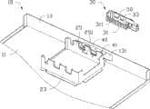
图1是本发明电子装置的一较佳实施方式的一立体分解图,其中电子装置中的线缆卡扣在一输入/输出设备中的一第一定位槽内。FIG. 1 is a three-dimensional exploded view of a preferred embodiment of the electronic device of the present invention, wherein a cable in the electronic device is buckled in a first positioning slot in an input/output device.
图2是本发明电子装置的一较佳实施方式的另一立体分解图,其中电子装置中的线缆卡扣在所述输入/输出设备中的一第二定位槽内,且仅揭示电子装置中的机壳与磁架的一部分。Fig. 2 is another perspective exploded view of a preferred embodiment of the electronic device of the present invention, wherein the cable in the electronic device is buckled in a second positioning slot in the input/output device, and only the electronic device is revealed part of the chassis and magnetic shelf in the
图3是图1的一立体组装图。FIG. 3 is a perspective assembly view of FIG. 1 .
图4是图2的一立体组装图。FIG. 4 is a perspective assembly view of FIG. 2 .
主要元件符号说明Description of main component symbols
具体实施方式Detailed ways
请参阅图1及图2,在本发明的一较佳实施方式中,一电子装置包括一机壳10(图中仅示一部分)及一输入/输出设备30。Please refer to FIG. 1 and FIG. 2 , in a preferred embodiment of the present invention, an electronic device includes a housing 10 (only a part is shown in the figure) and an input/
所述机壳10包括一底板11及一设在所述底板11一边缘上的前板13。在一较佳实施方式中,所述前板13垂直于所述底板11。The
所述底板11在靠近所述前板13安装一磁架20。所述磁架20用以安装磁碟机(图未示),包括有一固定在所述底板11上的基板21、及连接于所述基板21的两相对边缘的两安装板23、25。所述安装板25上开设有五个通孔251。所述前板13开设有一开口131,并在开口131的上方延伸有一电路板40。所述开口131用以供所述输入/输出设备30进出所述机壳10。所述电路板40开设有五个开孔41。在一较佳实施方式中,所述电路板40大致垂直于所述前板13;每一开孔41与每一通孔251的大小大致相等。A
所述输入/输出设备30包括有一第一侧壁31及一相邻于所述第一侧壁31的第二侧壁33。所述第一侧壁31开设有五个第一定位槽311,所述第二侧壁33开设有与每一第一定位槽311相通的第二定位槽331。每一第一定位槽311在与每一第一定位槽311的连接处形成有一凸块35。在一较佳实施方式中,所述第一定位槽311的宽度与所述第二定位槽331的宽度大致相等;所述第一定位槽311的长度大于所述第二定位槽331的长度;所述凸块35为一弧形凸块。The input/
所述输入/输出设备30的一侧连接有五条用以传输数据与信号的线缆50,另一侧开设有若干用以连接外接设备的接口(图未示)。每一线缆50相对所述第二侧壁33可位于一平行于所述第二侧壁33的第一位置或一垂直于所述第二侧壁33的第二位置。在第一位置时,所述凸块35卡扣住所述线缆50而使线缆50定位于所述第一定位槽311内;在第二位置时,所述凸块35卡扣住所述线缆50而使线缆50定位于所述第二定位槽331内。One side of the input/
请参阅图3将所述输入/输出设备30的线缆50定位在第一位置时,使所述线缆50由所述第一定位槽311延伸出,并对应穿过所述磁架20的安装板25上的通孔251,而插接在一电子元件(图未示)上。Referring to FIG. 3 , when the
请参阅图4,将所述输入/输出设备30的线缆50定位在第二位置时,所述线缆50由所述第二定位槽331延伸出,并对应穿过所述电路板40上的开孔41,而插接在该电子元件上。这样,即可根据机壳10内部的空间布局而选择所述线缆50的布局走向,以方便的安装所述线缆50。另外,这样也可以减小线缆50因碰撞而产生的损坏率。Please refer to FIG. 4 , when the
Claims (8)
Translated fromChinesePriority Applications (3)
| Application Number | Priority Date | Filing Date | Title |
|---|---|---|---|
| CN2011100462685ACN102650896A (en) | 2011-02-25 | 2011-02-25 | Electronic device |
| TW100106988ATW201235821A (en) | 2011-02-25 | 2011-03-02 | Electronic device |
| US13/289,999US8513521B2 (en) | 2011-02-25 | 2011-11-04 | Electronic device enclosure having a cable holding device |
Applications Claiming Priority (1)
| Application Number | Priority Date | Filing Date | Title |
|---|---|---|---|
| CN2011100462685ACN102650896A (en) | 2011-02-25 | 2011-02-25 | Electronic device |
Publications (1)
| Publication Number | Publication Date |
|---|---|
| CN102650896Atrue CN102650896A (en) | 2012-08-29 |
Family
ID=46692909
Family Applications (1)
| Application Number | Title | Priority Date | Filing Date |
|---|---|---|---|
| CN2011100462685APendingCN102650896A (en) | 2011-02-25 | 2011-02-25 | Electronic device |
Country Status (3)
| Country | Link |
|---|---|
| US (1) | US8513521B2 (en) |
| CN (1) | CN102650896A (en) |
| TW (1) | TW201235821A (en) |
Families Citing this family (4)
| Publication number | Priority date | Publication date | Assignee | Title |
|---|---|---|---|---|
| CN102811585A (en)* | 2011-06-02 | 2012-12-05 | 鸿富锦精密工业(深圳)有限公司 | electronic device |
| CN103901978A (en)* | 2012-12-27 | 2014-07-02 | 鸿富锦精密工业(武汉)有限公司 | Support for data storage device |
| DE102016007224A1 (en)* | 2015-08-04 | 2017-02-09 | Sew-Eurodrive Gmbh & Co Kg | Holding device and electrical appliance |
| CN106816763B (en)* | 2015-11-30 | 2019-01-08 | 英业达科技有限公司 | Connector limiting device and its server |
Family Cites Families (7)
| Publication number | Priority date | Publication date | Assignee | Title |
|---|---|---|---|---|
| DE7809938U1 (en)* | 1978-04-04 | 1978-08-17 | Standard Elektrik Lorenz Ag, 7000 Stuttgart | Cable holder |
| US5789702A (en)* | 1996-05-17 | 1998-08-04 | Perella; Paul | Modular component of appliance housing |
| DE19838951C1 (en)* | 1998-08-27 | 2000-05-04 | Schroff Gmbh | HF-tight bushing |
| DE10021064A1 (en)* | 2000-04-28 | 2001-11-15 | Bosch Gmbh Robert | Cover device |
| US6967283B2 (en)* | 2001-03-20 | 2005-11-22 | American Power Conversion Corporation | Adjustable scalable rack power system and method |
| DE102004058195A1 (en)* | 2004-12-02 | 2006-06-08 | Patent-Treuhand-Gesellschaft für elektrische Glühlampen mbH | Conductor holder |
| US7587795B2 (en)* | 2005-10-13 | 2009-09-15 | Yazaki Corporation | Flat cable bending holder |
- 2011
- 2011-02-25CNCN2011100462685Apatent/CN102650896A/enactivePending
- 2011-03-02TWTW100106988Apatent/TW201235821A/enunknown
- 2011-11-04USUS13/289,999patent/US8513521B2/ennot_activeExpired - Fee Related
Also Published As
| Publication number | Publication date |
|---|---|
| US8513521B2 (en) | 2013-08-20 |
| US20120217054A1 (en) | 2012-08-30 |
| TW201235821A (en) | 2012-09-01 |
Similar Documents
| Publication | Publication Date | Title |
|---|---|---|
| US7623344B2 (en) | Method and apparatus for mounting a fan in a chassis | |
| CN102854939B (en) | I/O port combinations | |
| US9523999B2 (en) | Adapter and information processing unit | |
| CN103313579A (en) | Electronic device and fan module thereof | |
| CN102548318A (en) | Electronic equipment | |
| CN102890544A (en) | Expansion card holder | |
| CN102902317A (en) | Fixing device for expansion cards | |
| US9075579B2 (en) | Mounting apparatus for expansion card | |
| TW201401978A (en) | Power module assembly of server | |
| US20120224340A1 (en) | Electronic device with mounting bracket for receiving expansion card and connector | |
| US20080212274A1 (en) | Air duct for directing airflow in a computer enclosure | |
| CN102650896A (en) | Electronic device | |
| TWI670583B (en) | Connecting Media Device and Server with the Connecting Media Device | |
| CN102811585A (en) | electronic device | |
| TWI618474B (en) | Electronic device | |
| CN102385423B (en) | Electronic installation | |
| CN103513699A (en) | Installation assembly | |
| US8824157B2 (en) | Mounting apparatus for expansion cards | |
| CN102740665A (en) | Anti-electromagnetic interference elastic sheet and electronic apparatus adopting same | |
| US20130322006A1 (en) | Computer enclosure and mounting assembly for data storage device of the same | |
| CN103376841A (en) | Electronic device shell with cable sorting rack | |
| CN106061181A (en) | Electronic module | |
| CN103513704A (en) | Electronic device and expansion card thereof | |
| CN102999090A (en) | Servo device | |
| CN102447193A (en) | Electric connector |
Legal Events
| Date | Code | Title | Description |
|---|---|---|---|
| C06 | Publication | ||
| PB01 | Publication | ||
| C02 | Deemed withdrawal of patent application after publication (patent law 2001) | ||
| WD01 | Invention patent application deemed withdrawn after publication | Application publication date:20120829 |