CN102644899B - Design method of light-emitting diode (LED) illuminating lens - Google Patents
Design method of light-emitting diode (LED) illuminating lensDownload PDFInfo
- Publication number
- CN102644899B CN102644899BCN2011100403564ACN201110040356ACN102644899BCN 102644899 BCN102644899 BCN 102644899BCN 2011100403564 ACN2011100403564 ACN 2011100403564ACN 201110040356 ACN201110040356 ACN 201110040356ACN 102644899 BCN102644899 BCN 102644899B
- Authority
- CN
- China
- Prior art keywords
- lens
- shape
- point
- illuminated
- incident
- Prior art date
- Legal status (The legal status is an assumption and is not a legal conclusion. Google has not performed a legal analysis and makes no representation as to the accuracy of the status listed.)
- Active
Links
Images


Landscapes
- Led Device Packages (AREA)
- Non-Portable Lighting Devices Or Systems Thereof (AREA)
Abstract
Translated fromChineseDescription
Translated fromChinese技术领域technical field
本发明涉及一种光学元件的设计方法,更具体地说,涉及一种给定双通光面透镜的任一面的表面曲率分布、求透镜另一面形状的设计方法。The invention relates to a design method of an optical element, more specifically, to a design method for calculating the shape of the other side of the lens given the surface curvature distribution of any one side of a double-pass optical surface lens.
背景技术Background technique
非成像光学透镜的设计在LED照明领域是一个非常关键的步骤。LED灯具所用的透镜结构是为满足不同的照明要求和照明场合进行设计的,比如,道路用照明、景观用照明等。目前,很多LED照明用透镜的设计方法仅限于将透镜的入射面固定为不影响光线走向的球面,然后对透镜的出射面进行设计。这种结构的透镜,只有其出射面对配光的要求做了贡献,而入射面对光线的走向并不产生任何影响,因此没有做出任何贡献。这种只依赖出射面来配光的设计方法得到的透镜在实际使用时势必会受到很大的局限性,对一些配光的要求也无法满足。还有,在对透镜的安装以及外观有比较严格要求的场合下,现有透镜的设计方法也很难达到实际使用的要求,而且也无法做到透镜的模块化,不能提高透镜的生产和安装效率。The design of non-imaging optical lens is a very critical step in the field of LED lighting. The lens structure used in LED lamps is designed to meet different lighting requirements and lighting occasions, such as road lighting, landscape lighting, etc. At present, many design methods of lenses for LED lighting are limited to fixing the incident surface of the lens as a spherical surface that does not affect the light direction, and then designing the exit surface of the lens. For the lens with this structure, only the outgoing surface contributes to the light distribution requirements, while the incident surface does not have any influence on the direction of the light, so it does not make any contribution. The lens obtained by this design method that only relies on the exit surface for light distribution is bound to suffer from great limitations in actual use, and cannot meet some light distribution requirements. In addition, in the case of relatively strict requirements on the installation and appearance of the lens, it is difficult for the existing lens design method to meet the requirements of actual use, and it is also impossible to achieve modularization of the lens, and cannot improve the production and installation of the lens. efficiency.
发明内容Contents of the invention
本发明为解决上述现有技术中存在的技术问题,提供一种LED照明用透镜的设计方法,采用该方法,可以在给定透镜任一面的任意表面曲率分布时,进行透镜另一面的形状设计,不仅满足透镜的各种配光需要,而且满足对透镜形状的特殊要求。该方法灵活、简单,适用于各种类型的LED。In order to solve the technical problems in the above-mentioned prior art, the present invention provides a method for designing a lens for LED lighting. By using this method, the shape of the other side of the lens can be designed when any surface curvature distribution on one side of the lens is given. , not only meet the various light distribution needs of the lens, but also meet the special requirements for the shape of the lens. The method is flexible, simple, and applicable to various types of LEDs.
为达到上述目的,本发明采用的技术方案如下:In order to achieve the above object, the technical scheme adopted in the present invention is as follows:
一种LED照明用透镜的设计方法,所述透镜由入射面和出射面组成,其中任一面的表面曲率分布为预先给定,求另一面形状的设计步骤如下:A design method of a lens for LED lighting, the lens is composed of an incident surface and an outgoing surface, wherein the surface curvature distribution of any one surface is predetermined, and the design steps for obtaining the shape of the other surface are as follows:
a)、以过LED光轴的一个平面为计算面,在该计算面上,将LED光轴任一侧的半光束角按照光源的发光强度随发光角度的分布规律划分成多个小角,使得各个小角内的光通量相等;a) Taking a plane passing through the LED optical axis as the calculation plane, on the calculation plane, the half-beam angle on either side of the LED optical axis is divided into multiple small angles according to the distribution of the luminous intensity of the light source with the luminous angle, so that The luminous flux in each small angle is equal;
b)、在所述半光束角范围内,将所述计算面与被照区域的交线段分成与所述小角数量相等的多个小段,每一小角对应一个小段;调整各小段的长度使其与LED到该小段上任一被照点的距离的平方成反比,并且与预先给定的照度随被照点离开被照区域中心的距离而变化的函数值成反比;b), within the range of the half beam angle, divide the intersection line segment between the calculation surface and the illuminated area into a plurality of small segments equal to the number of small angles, each small angle corresponds to a small segment; adjust the length of each small segment so that It is inversely proportional to the square of the distance from the LED to any illuminated point on the segment, and is inversely proportional to the function value of the predetermined illuminance changing with the distance from the illuminated point to the center of the illuminated area;
c)、若所述入射面的表面曲率分布为预先给定,根据透镜离开LED距离的要求以及透镜厚度的要求在光轴上取一点作为出射面的起始特征点,从以光轴为角边的第一小角开始,以该小角的另一角边为入射光线,由折射定律,确定该条入射光线经过入射面后的折射光线;在出射面的起始特征点处做一垂直于光轴的垂线,所述垂线与所述折射光线相交于一点,该点即为出射面的第一特征点;以所述折射光线为出射面在第一特征点处的入射光线,以在该第一特征点处,平行于LED与对应第一被照小段上任意被照点连线的直线为出射光线,由折射定律,求得出射面的第二特征点的位置;依照此方法,依次求得出射面的各个特征点的位置,将各特征点依次连接,即可得到出射面在所述计算面上的截面形状;c) If the surface curvature distribution of the incident surface is given in advance, according to the requirements of the distance from the lens to the LED and the thickness of the lens, a point is taken on the optical axis as the starting feature point of the exit surface, from the angle of the optical axis Starting from the first small angle of the side, taking the other side of the small angle as the incident ray, the refracted ray after the incident ray passes through the incident surface is determined by the law of refraction; , the perpendicular line intersects the refracted ray at one point, which is the first characteristic point of the exit surface; the incident ray at the first characteristic point of the exit surface is taken as the refracted ray, and the At the first feature point, the straight line parallel to the line connecting the LED and any illuminated point corresponding to the first illuminated section is the outgoing ray, and the position of the second feature point on the exit surface is obtained by the law of refraction; according to this method, sequentially The position of each feature point of the exit surface is obtained, and the feature points are connected in turn to obtain the cross-sectional shape of the exit surface on the calculation surface;
d)、若所述出射面的表面曲率分布为预先给定,从以光轴为角边的第一小角开始,在与该第一小角对应的第一被照小段上,平行于LED与该第一被照小段上的任意被照点连线的直线为出射光线方向,由折射定律,求得出射面上相应于第一被照小段的入射光线方向,依照此方法,求得出射面上相应于各被照小段的各入射光线方向,并将它们作为入射面上各折射光线的方向;根据透镜离开LED距离的要求以及透镜厚度的要求在光轴上取一点作为入射面的起始特征点,在该起始特征点处做一垂线与第一小角的角边相交,交点即作为入射面的第一特征点;由折射定律,求得入射面的第二特征点的位置;依照此方法,依次求得入射面的各个特征点的位置,将各特征点依次连接形成一条曲线,即可得到入射面在所述计算面上的截面形状;d) If the surface curvature distribution of the exit surface is given in advance, starting from the first small angle with the optical axis as the angle side, on the first illuminated segment corresponding to the first small angle, parallel to the LED and the The straight line connecting any illuminated points on the first illuminated segment is the direction of the outgoing light. According to the law of refraction, the direction of the incident light on the incident surface corresponding to the first illuminated segment can be obtained. According to this method, the direction of the incident light on the incident surface can be obtained. Corresponding to the direction of each incident light of each illuminated segment, and take them as the direction of each refracted light on the incident surface; according to the requirements of the distance from the lens to the LED and the thickness of the lens, take a point on the optical axis as the initial feature of the incident surface Point, draw a vertical line at the starting feature point to intersect with the corner of the first small angle, and the intersection point is the first feature point of the incident surface; by the law of refraction, the position of the second feature point of the incident surface is obtained; according to In this method, the position of each feature point of the incident surface is sequentially obtained, and each feature point is sequentially connected to form a curve, so that the cross-sectional shape of the incident surface on the calculation surface can be obtained;
e)、重复上述步骤a)~d),确定透镜另一面在多个均匀分布的计算面上的多个截面形状;e) Repeat steps a) to d) above to determine multiple cross-sectional shapes of the other side of the lens on multiple evenly distributed calculation surfaces;
f)、将上述求得的多个截面形状依次连接起来,即可得到所求的透镜另一面的形状。f) Connect the multiple cross-sectional shapes obtained above sequentially to obtain the obtained shape of the other side of the lens.
所述透镜关于一个平面呈对称分布,所述e)步骤中,在对称面一侧的两个象限内多次重复所述步骤a)~d),确定透镜另一面在该两个象限内的多个均匀分布的计算面上的多个截面形状,将求得的多个截面形状依次连接起来,得到所求的透镜另一面在该两个象限内的形状,再通过该平面对称,求得所求的透镜另一面的全部形状。The lenses are distributed symmetrically with respect to a plane, and in the step e), the steps a) to d) are repeated multiple times in the two quadrants on one side of the symmetric plane, and it is determined that the other side of the lens is in the two quadrants Multiple cross-sectional shapes on multiple uniformly distributed calculation surfaces are sequentially connected to obtain the shape of the other side of the lens in the two quadrants, and then through the plane symmetry, obtain The entire shape of the other side of the lens to be obtained.
所述透镜关于两个平面呈对称分布,所述e)步骤中,在由该两个对称面限定的一个象限内多次重复所述步骤a)~d),确定所求的透镜另一面在该象限内的多个均匀分布的计算面上的多个截面形状,将求得的多个截面形状依次连接起来,得到所求的透镜另一面在该象限内的形状,再通过两次平面对称,求得所求的透镜另一面的全部形状。The lenses are distributed symmetrically with respect to two planes. In the step e), the steps a) to d) are repeated multiple times in a quadrant defined by the two planes of symmetry, and it is determined that the other side of the lens is at Multiple cross-sectional shapes on multiple uniformly distributed calculation surfaces in this quadrant are sequentially connected to obtain the shape of the other side of the lens in this quadrant, and then through two plane symmetry , to obtain the entire shape of the other side of the lens.
所述透镜关于N个平面呈对称分布,所述e)步骤中,在180°/N范围内多次重复所述步骤a)~d),确定所求的透镜另一面在180°/N范围内的多个均匀分布的计算面上的多个截面形状,将求得的多个截面形状依次连接起来,得到所求的透镜另一面在该180°/N范围内的形状,再通过N次平面对称,求得所求的透镜另一面的全部形状,其中N≥3。The lenses are distributed symmetrically with respect to N planes. In the step e), repeat the steps a) to d) multiple times within the range of 180°/N, and determine that the other side of the lens is within the range of 180°/N Multiple cross-sectional shapes on multiple uniformly distributed calculation surfaces in the interior, connect the obtained multiple cross-sectional shapes in sequence to obtain the shape of the other side of the lens within the range of 180°/N, and then pass N times Plane symmetry, obtain the entire shape of the other side of the lens, where N≥3.
一种LED照明用旋转对称透镜的设计方法,所述透镜由入射面和出射面组成,所述任一面的表面曲率分布为预先给定,求另一面形状的设计步骤同上述的LED照明用透镜的设计方法中的步骤a)~d),然后,将所求得的透镜另一面在所述计算面上的截面形状绕光轴旋转360°,即可得到所求的透镜另一面的全部形状。A design method of a rotationally symmetric lens for LED lighting, the lens is composed of an incident surface and an outgoing surface, the surface curvature distribution of any one surface is predetermined, and the design steps for finding the shape of the other surface are the same as the above-mentioned lens for LED lighting Steps a) to d) in the design method, and then, rotate the obtained cross-sectional shape of the other surface of the lens on the calculation surface by 360° around the optical axis to obtain the entire shape of the other surface of the lens .
所述预先给定的任一面可以是平面、平面拼接面、曲面以及平面和曲面的结合。The predetermined any surface may be a plane, a plane joining surface, a curved surface and a combination of a plane and a curved surface.
所述c)、d)步骤中,各特征点依次用直线或者平滑的曲线连接起来。In steps c) and d), each feature point is sequentially connected by a straight line or a smooth curve.
所述多个截面形状依次用平滑的曲面连接起来。The plurality of cross-sectional shapes are sequentially connected by smooth curved surfaces.
所述透镜的侧周向外顺势延伸。The side circumference of the lens extends outward along the trend.
所述透镜采用折射率为1.3~4.2的透明材料。The lens adopts a transparent material with a refractive index of 1.3-4.2.
所述c)步骤中,以所述折射光线为出射面的第一特征点的入射光线,以在该第一特征点处,平行于LED与对应第一被照小段上的边缘被照点连线的直线为出射光线,由折射定律,确定该第一特征点的法线;以第二小角的角边为入射光线,由折射定律,求得该入射光线经过入射面后的折射光线,在所述计算面上,垂直于所述法线的直线与该折射光线相交,交点即作为出射面的第二特征点。In the step c), the refracted ray is used as the incident ray of the first characteristic point on the exit surface, and at the first characteristic point, it is parallel to the LED and connected to the edge illuminated point on the corresponding first illuminated segment. The straight line of the line is the outgoing ray, and the normal of the first feature point is determined by the law of refraction; the angle side of the second small angle is used as the incident ray, and the refracted ray after the incident ray passes through the incident surface is obtained by the law of refraction. On the calculation surface, a straight line perpendicular to the normal intersects the refracted ray, and the intersection point is used as a second feature point of the exit surface.
所述d)步骤中,由折射定律,确定入射面的第一特征点的法线,在所述计算面上,垂直于所述法线的直线与第二小角的角边相交于一点,交点即作为入射面的第二特征点。In the step d), the normal of the first feature point of the incident surface is determined by the law of refraction, and on the calculation surface, a straight line perpendicular to the normal intersects the side of the second small angle at one point, and the intersection point That is, as the second feature point of the incident surface.
本发明所公开的LED照明用透镜的设计方法,对透镜的任一面根据实际需要设定任意的表面曲率分布规律,可以为平面的、曲面的或平面和曲面的结合,同时,照射的光斑也可根据实际使用场合和照明要求进行具体的形状设定。在LED与被照区域之间建立起一定的对应关系,再对透镜的入射面和出射面根据折射定律,确定出若干个特征点,连接各个特征点形成所求透镜的一面的一个截面形状,重复该步骤多次,求得所求透镜的一面的多个截面形状,连接该多个截面形状即可形成所求透镜的一面的全部形状。当所取得的特征点以及所形成的截面的数量足够多时,就能形成表面比较平滑的透镜形状。In the design method of the lens for LED lighting disclosed in the present invention, any surface curvature distribution law can be set according to actual needs on any surface of the lens, which can be a plane, a curved surface, or a combination of a plane and a curved surface. Specific shape settings can be made according to actual use occasions and lighting requirements. Establish a certain correspondence between the LED and the illuminated area, and then determine a number of feature points for the incident surface and the exit surface of the lens according to the law of refraction, and connect each feature point to form a cross-sectional shape of one side of the lens. Repeat this step multiple times to obtain multiple cross-sectional shapes of one side of the desired lens, and connect the multiple cross-sectional shapes to form all the shapes of one side of the desired lens. When the obtained feature points and the number of formed cross-sections are large enough, a lens shape with a relatively smooth surface can be formed.
附图说明Description of drawings
以下通过附图对本发明透镜设计方法做进一步详细的描述:The lens design method of the present invention is further described in detail by the accompanying drawings:
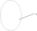
图1是给定透镜的被照区域形状为椭圆形的示意图;Fig. 1 is the schematic diagram that the shape of the illuminated area of a given lens is an ellipse;
图2是给定图1所示透镜的出射面为平面的形状示意图;Fig. 2 is a schematic diagram of the shape given that the exit surface of the lens shown in Fig. 1 is a plane;
图3是在一个计算面上LED光轴单侧光束角内划分小角的方法示意图;Fig. 3 is a schematic diagram of a method for dividing small angles within the beam angle on one side of the LED optical axis on a calculation surface;
图4是在图1所示的被照区域上划分小段的方法示意图;Fig. 4 is a schematic diagram of a method for dividing subsections on the illuminated area shown in Fig. 1;
图5是确定图1所示透镜的入射面的各特征点的位置并依次连接形成一个截面形状的方法一示意图;Fig. 5 is a schematic diagram of a method for determining the position of each feature point of the incident surface of the lens shown in Fig. 1 and sequentially connecting them to form a cross-sectional shape;
图6是将图5所示各特征点依次连接形成一个截面形状的方法二示意图;Fig. 6 is a schematic diagram of a second method for sequentially connecting each feature point shown in Fig. 5 to form a cross-sectional shape;
图7是图1所示透镜在另一计算面上的截面形状示意图;Fig. 7 is a schematic diagram of the cross-sectional shape of the lens shown in Fig. 1 on another calculation plane;
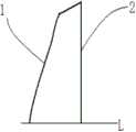
图8是图1所示透镜在一个象限内的结构示意图;Fig. 8 is a schematic structural view of the lens shown in Fig. 1 in a quadrant;
图9是本发明设计方法得到的图1所示透镜的立体图;Fig. 9 is a perspective view of the lens shown in Fig. 1 obtained by the design method of the present invention;
图10是给定透镜的被照区域形状为圆形的示意图;Fig. 10 is a schematic diagram in which the shape of the illuminated area of a given lens is circular;
图11是给定图10所示透镜的出射面为平面的形状示意图;Fig. 11 is a schematic diagram of the shape given that the exit surface of the lens shown in Fig. 10 is a plane;
图12是在一个计算面上LED光轴单侧光束角内划分小角的方法示意图;Fig. 12 is a schematic diagram of a method for dividing small angles within the beam angle on one side of the LED optical axis on a calculation surface;
图13是图10所示的被照区域上划分小段的方法示意图;Fig. 13 is a schematic diagram of a method for dividing subsections in the illuminated area shown in Fig. 10;
图14是确定图10所示透镜的入射面的各特征点的位置并依次连接形成一个截面形状的方法一示意图;Fig. 14 is a schematic diagram of a method for determining the position of each feature point of the incident surface of the lens shown in Fig. 10 and sequentially connecting them to form a cross-sectional shape;
图15是将图14所示各特征点依次连接形成一个截面形状的方法二示意图;Fig. 15 is a schematic diagram of a second method for sequentially connecting each feature point shown in Fig. 14 to form a cross-sectional shape;
图16是本发明设计方法得到的图10所示透镜的立体图;Fig. 16 is a perspective view of the lens shown in Fig. 10 obtained by the design method of the present invention;
图17是给定透镜的被照区域形状为圆形的示意图;Fig. 17 is a schematic diagram in which the shape of the illuminated area of a given lens is circular;
图18是给定图17所示透镜的入射面为平面的形状示意图;Fig. 18 is a schematic diagram of the shape of the plane given that the incident surface of the lens shown in Fig. 17 is plane;
图19是在一个计算面上LED光轴单侧光束角内划分小角的方法示意图;Fig. 19 is a schematic diagram of a method for dividing small angles within the beam angle on one side of the LED optical axis on a calculation surface;
图20是图17所示的被照区域上划分小段的方法示意图;Fig. 20 is a schematic diagram of a method for dividing subsections in the illuminated area shown in Fig. 17;
图21是确定图17所示透镜的出射面的各特征点的位置并依次连接形成一个截面形状的方法一示意图;Fig. 21 is a schematic diagram of a method for determining the position of each feature point on the exit surface of the lens shown in Fig. 17 and sequentially connecting them to form a cross-sectional shape;
图22是将图21所示各特征点依次连接形成一个截面形状的方法二示意图;Fig. 22 is a schematic diagram of a second method for sequentially connecting each feature point shown in Fig. 21 to form a cross-sectional shape;
图23是本发明设计方法得到的图17所示透镜的立体图。Fig. 23 is a perspective view of the lens shown in Fig. 17 obtained by the design method of the present invention.
具体实施方式Detailed ways
图1~图9所示是本发明设计方法的第一实施例,给定透镜的被照区域形状为如图2所示的椭圆形,给定该透镜出射面2为如图1所示的平面。该椭圆的长轴为x,短轴为y。该透镜关于过光轴L和长轴x所在的平面以及与该平面垂直的平面均呈对称分布,求透镜入射面1的形状。因为本实施例的透镜关于过光轴L和长轴x所在的平面以及与该平面垂直的平面均呈对称分布,因此只需求出透镜在由该两个对称面所限定的一个象限内的立体形状,然后通过两次平面对称,即可得到整个透镜的立体形状。Shown in Fig. 1~Fig. 9 is the first embodiment of the design method of the present invention, the shape of the illuminated region of the given lens is ellipse as shown in Fig. 2, and the given
图3所示,以过LED光源O的光轴L和椭圆的长轴x所在的平面为一个计算面,在该计算面上,以光轴L为一角边,将位于光轴单侧的半光束角按照LED光源O的发光强度随发光角度的分布规律划分成多个小角,并使得各个小角内的光通量相等。为了图示和描述清晰起见,本实施例仅划分成了四个小角,分别为第一小角α1,第二小角α2,第三小角α3,第四小角α4。As shown in Figure 3, take the plane where the optical axis L of the LED light source O and the long axis x of the ellipse are located as a calculation plane, and on this calculation plane, take the optical axis L as an angle side, and the half of the ellipse located on one side of the optical axis The beam angle is divided into multiple small angles according to the distribution law of the luminous intensity of the LED light source O with the luminous angle, and the luminous flux in each small angle is equal. For clarity of illustration and description, this embodiment is only divided into four small angles, namely the first small angle α1 , the second small angle α2 , the third small angle α3 , and the fourth small angle α4 .
图4所示,将该计算面与该被照椭圆形区域的长轴x的交线段也分成4个小段,分别为第一被照小段ab、第二被照小段bc、第三被照小段cd、第四被照小段de,并分别与小角α1,α2,α3,α4一一对应。调整各被照小段的长度,使其与LED光源O到该被照小段上任意一个被照点的距离的平方成反比(因为被照小段的长度与LED光源O到该被照小段上各被照点的距离相比较而言非常小,所以,各被照小段上任一被照点均可代表该被照小段的特性),并且与该被照点的照度随被照点离开被照区域中心点的距离而变化的函数值成反比。本实施例为描述简单起见,设定被照区域的照度为均匀照度,即该函数为一定值。As shown in Figure 4, the intersection line segment between the calculation surface and the long axis x of the illuminated elliptical area is also divided into four small segments, which are respectively the first illuminated segment ab, the second illuminated segment bc, and the third illuminated segment cd, the fourth illuminated segment de, and corresponding to the small angles α1, α2, α3, α4 respectively. Adjust the length of each illuminated section so that it is inversely proportional to the square of the distance from the LED light source O to any illuminated point on the illuminated section (because the length of the illuminated section is the same as the length of the illuminated section from the LED light source O to each illuminated point on the illuminated section). The distance between the illuminated points is very small, so any illuminated point on each illuminated segment can represent the characteristics of the illuminated segment), and the illuminance of the illuminated point moves away from the center of the illuminated area as the illuminated point The function value varies inversely proportional to the distance from the point. In this embodiment, for simplicity of description, the illuminance of the illuminated area is set to be uniform illuminance, that is, the function is a certain value.
图5所示,首先,在该计算面上,从以光轴L为角边的第一小角α1开始设计,在与该第一小角α1对应的第一被照小段ab上,平行于LED光源O与该第一被照小段ab上的被照点b连线的直线为出射光线方向,由折射定律,求得出射面2上相应于第一被照小段ab的入射光线方向。依照此方法,求得出射面2上相应于第二、第三、第四被照小段的各入射光线方向,并将它们作为入射面1上的各折射光线的方向。根据透镜离开LED光源O距离的要求以及透镜厚度的要求在光轴L上取一点作为入射面1的起始特征点0a,在该起始特征点0a处做一垂直于光轴L的垂线,该垂线与第一小角α1的另一角边相交,交点即作为入射面1的第一特征点1a,由折射定律,确定该第一特征点1a处的法线n1。在该计算面上,垂直于该法线n1的直线与第二小角α2的角边相交于一点,交点即为入射面1的第二特征点2a。依照此方法,依次求得入射面1的第三特征点3a和第四特征点4a的位置,将各特征点依次连接形成一条曲线,As shown in Figure 5, firstly, on the calculation plane, start from the first small angle α1 with the optical axis L as the corner side, and on the first illuminated segment ab corresponding to the first small angle α1, parallel to the LED light source The straight line connecting O and the illuminated point b on the first illuminated segment ab is the direction of the outgoing light, and the direction of the incident light corresponding to the first illuminated segment ab on the
图5是将各特征点用直线依次连接,图6是将各特征点用平滑的曲线依次连接,即可得到入射面1在所述计算面上的截面形状;Fig. 5 connects each characteristic point with straight line successively, and Fig. 6 connects each characteristic point with smooth curve successively, can obtain the cross-sectional shape of
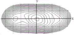
在由该透镜的两个对称面所限定的一个象限内,均匀选取过LED光源O的光轴L的多个平面分别作为计算面,按照同前述完全相同的方法,得到入射面1在该多个计算面上的多个截面形状。本实施例为描述清楚起见,仅图示了两个具有代表性的计算面上的截面形状,分别为图5和图6所示的过椭圆形被照区域的长轴x的计算面上的截面形状以及图7所示的过椭圆形被照区域的短轴y的计算面上的截面形状。In a quadrant defined by the two symmetric planes of the lens, a plurality of planes evenly passing through the optical axis L of the LED light source O are selected as the calculation planes respectively, and according to the same method as above, the
将图6和图7所示的截面形状用平滑的曲面连接起来,形成透镜入射面1在所述象限内的立体形状,该形状如图8所示。然后,通过两次平面对称,即可得到本实施例透镜入射面1的全部立体形状,从而得到如图9所示的整个透镜的立体形状。Connect the cross-sectional shapes shown in FIG. 6 and FIG. 7 with a smooth curved surface to form a three-dimensional shape of the
图10~图16所示是本发明设计方法的第二实施例,给定透镜的被照区域为如图11所示的圆形,并且给定该透镜出射面2的形状为如图10所示的平面。该透镜是以光轴L为旋转轴的旋转对称形状,求透镜入射面1的形状。因为本实施例的透镜是以光轴L为旋转轴的旋转对称形状,因此只需求出透镜入射面1的过光轴L的一个截面形状,然后以光轴L为旋转轴旋转360°,即可得到入射面1的立体形状,也即得到整个透镜的形状。Shown in Fig. 10~Fig. 16 is the second embodiment of the design method of the present invention, the illuminated area of given lens is circular as shown in Fig. 11, and the shape of given this
图12~图15所示,在LED光源O处划分小角以及在被照区域上划分小段的方法与上述实施例所描述的步骤完全相同。将所求得的如图15所示的截面形状绕光轴L旋转360°,即可得到透镜入射面1的立体形状,也即得到如图16所示的整个透镜的立体形状。As shown in FIGS. 12 to 15 , the methods of dividing small corners at the LED light source O and dividing small segments on the illuminated area are exactly the same as the steps described in the above-mentioned embodiments. By rotating the obtained cross-sectional shape as shown in FIG. 15 by 360° around the optical axis L, the three-dimensional shape of the
图17~图23所示是本发明设计方法的第三实施例,给定透镜的被照区域为图18所示的圆形,并且给定该透镜入射面1的形状为图17所示的平面。该透镜是以光轴L为旋转轴的旋转对称形状,求透镜出射面2的形状。因为本实施例的透镜是以光轴L为旋转轴的旋转对称形状,因此只需求出透镜出射面2的过光轴L的一个截面形状,然后以光轴L为旋转轴旋转360°,即可得到出射面2的立体形状,也即得到整个透镜的形状。Figures 17 to 23 show the third embodiment of the design method of the present invention, the illuminated area of the given lens is circular as shown in Figure 18, and the shape of the
图19~图20所示,在LED光源O处划分小角以及在被照区域上划分小段的方法与上述两个实施例所描述的步骤完全相同。As shown in FIGS. 19 to 20 , the methods of dividing small corners at the LED light source O and dividing small segments on the illuminated area are exactly the same as the steps described in the above two embodiments.
图21所示,首先,在所取的计算面上,根据透镜离开LED光源O距离的要求以及透镜厚度的要求在光轴L上取一点作为出射面2的起始特征点0b。从第一小角α1开始设计,以该第一小角α1的角边为入射光线,由折射定律,求得该条入射光线经过入射面1后的折射光线,该折射光线也即射向出射面2上的入射光线。在出射面2的起始特征点0b处做一垂直于光轴L的垂线,该垂线与该折射光线相交于一点,该点即作为出射面2的第一特征点1b。以经过出射面2的第一特征点1b且平行于LED光源O与第一被照小段ab上的被照点b连线的直线为折射光线,由折射定律,确定出射面2的第一特征点1b处的法线n1。以第二小角α2的另一角边为入射光线,由折射定律,求得该入射光线经过入射面1后的折射光线。在该计算面上,垂直于法线n1的直线与该折射光线相交,交点即为出射面2的第二特征点2b。依照此方法,依次求得出射面2的第三特征点3b和第四特征点4b的位置,将各特征点依次连接形成一条曲线。As shown in FIG. 21 , first, on the calculated surface, a point on the optical axis L is taken as the starting feature point 0b of the
图21是将各特征点用直线依次连接,图22是将各特征点用平滑的曲线依次连接,即可形成出射面2在该计算面上的截面形状。将该截面形状绕光轴L旋转360°,即可得到透镜出射面2的立体形状,也即得到如图23所示的整个透镜的立体形状。Fig. 21 connects the feature points sequentially with straight lines, and Fig. 22 connects the feature points sequentially with smooth curves to form the cross-sectional shape of the
上述三个实施例所得到的透镜,其侧周均可向外顺势延伸,增大透镜的通光面,将LED光源O在光束角之外发出的光线也能充分利用到,从而进一步提高光线的利用率。For the lenses obtained in the above three embodiments, the side circumferences can extend outward along the trend, so that the light-transmitting surface of the lens can be enlarged, and the light emitted by the LED light source O outside the beam angle can also be fully utilized, thereby further improving the light intensity. utilization rate.
以上实施例仅作为对本发明设计方法的一个说明,本发明设计方法所涵盖的范围应该包括在给定透镜一个面的曲率分布规律以及被照区域形状时,求透镜另一面形状的所有情况。The above embodiment is only used as an illustration of the design method of the present invention, and the scope covered by the design method of the present invention should include all situations in which the shape of the other surface of the lens is obtained when the curvature distribution law of one surface of the lens and the shape of the illuminated area are given.
Claims (10)
Translated fromChinesePriority Applications (1)
| Application Number | Priority Date | Filing Date | Title |
|---|---|---|---|
| CN2011100403564ACN102644899B (en) | 2011-02-18 | 2011-02-18 | Design method of light-emitting diode (LED) illuminating lens |
Applications Claiming Priority (1)
| Application Number | Priority Date | Filing Date | Title |
|---|---|---|---|
| CN2011100403564ACN102644899B (en) | 2011-02-18 | 2011-02-18 | Design method of light-emitting diode (LED) illuminating lens |
Publications (2)
| Publication Number | Publication Date |
|---|---|
| CN102644899A CN102644899A (en) | 2012-08-22 |
| CN102644899Btrue CN102644899B (en) | 2013-07-31 |
Family
ID=46657890
Family Applications (1)
| Application Number | Title | Priority Date | Filing Date |
|---|---|---|---|
| CN2011100403564AActiveCN102644899B (en) | 2011-02-18 | 2011-02-18 | Design method of light-emitting diode (LED) illuminating lens |
Country Status (1)
| Country | Link |
|---|---|
| CN (1) | CN102644899B (en) |
Cited By (1)
| Publication number | Priority date | Publication date | Assignee | Title |
|---|---|---|---|---|
| CN103775969A (en)* | 2014-01-30 | 2014-05-07 | 上海战古电子科技有限公司 | Curtain wall type illuminating device with large light distribution area and design method thereof |
Families Citing this family (2)
| Publication number | Priority date | Publication date | Assignee | Title |
|---|---|---|---|---|
| CN105278102B (en)* | 2015-11-19 | 2018-02-16 | 上海三思电子工程有限公司 | A kind of method that LED lens are designed using deflection of light capability distribution method |
| CN105953175B (en)* | 2016-06-20 | 2022-09-06 | 浙江光锥科技有限公司 | Projecting lamp lens, have light-emitting module and projecting lamp of this projecting lamp lens |
Citations (5)
| Publication number | Priority date | Publication date | Assignee | Title |
|---|---|---|---|---|
| CN1058474A (en)* | 1990-07-24 | 1992-02-05 | 庄臣及庄臣视力产品有限公司 | Lens design method and resulting non-spherical lens |
| JP2001517855A (en)* | 1997-09-23 | 2001-10-09 | テレダイン・ライティング・アンド・ディスプレイ・プロダクツ・インコーポレーテッド | Illumination lens designed by extrinsic differential geometry |
| EP1762776A1 (en)* | 2005-09-09 | 2007-03-14 | Valeo Vision | Method for the manufacturing of a module or a vehicle headlamp |
| CN1928624A (en)* | 2006-09-29 | 2007-03-14 | 清华大学 | Design method of three-dimensional optical lens and lens |
| CN101858557A (en)* | 2010-06-12 | 2010-10-13 | 北京航空航天大学 | A secondary optical lens for LED street lamp and its design method |
- 2011
- 2011-02-18CNCN2011100403564Apatent/CN102644899B/enactiveActive
Patent Citations (5)
| Publication number | Priority date | Publication date | Assignee | Title |
|---|---|---|---|---|
| CN1058474A (en)* | 1990-07-24 | 1992-02-05 | 庄臣及庄臣视力产品有限公司 | Lens design method and resulting non-spherical lens |
| JP2001517855A (en)* | 1997-09-23 | 2001-10-09 | テレダイン・ライティング・アンド・ディスプレイ・プロダクツ・インコーポレーテッド | Illumination lens designed by extrinsic differential geometry |
| EP1762776A1 (en)* | 2005-09-09 | 2007-03-14 | Valeo Vision | Method for the manufacturing of a module or a vehicle headlamp |
| CN1928624A (en)* | 2006-09-29 | 2007-03-14 | 清华大学 | Design method of three-dimensional optical lens and lens |
| CN101858557A (en)* | 2010-06-12 | 2010-10-13 | 北京航空航天大学 | A secondary optical lens for LED street lamp and its design method |
Non-Patent Citations (2)
| Title |
|---|
| 丁毅,郑臻荣,顾培夫.实现LED照明的自由曲面透镜设计.《光子学报》.2009,第38卷(第6期),全文.* |
| 李澄,李农.一种用于均匀照明的LED透镜设计方法.《照明工程学报》.2010,第21卷(第3期),全文.* |
Cited By (2)
| Publication number | Priority date | Publication date | Assignee | Title |
|---|---|---|---|---|
| CN103775969A (en)* | 2014-01-30 | 2014-05-07 | 上海战古电子科技有限公司 | Curtain wall type illuminating device with large light distribution area and design method thereof |
| CN103775969B (en)* | 2014-01-30 | 2019-02-05 | 上海战古电子科技有限公司 | The lighting device and its design method of the big light distribution area of curtain wall type |
Also Published As
| Publication number | Publication date |
|---|---|
| CN102644899A (en) | 2012-08-22 |
Similar Documents
| Publication | Publication Date | Title |
|---|---|---|
| CN101619834B (en) | An apparatus and method for improved illumination area fill | |
| US10539292B2 (en) | Optical device and luminaire | |
| US20110320024A1 (en) | Optical element of lighting device and design method of the same | |
| TW201832381A (en) | Array with light-emitting diodes and variable lenses | |
| CN104613416B (en) | The design method of all-round smooth light-distribution lens and corresponding light-distribution lens | |
| CN104896425B (en) | A kind of LED free-form surface lens for light microscope illuminator | |
| CN105351885B (en) | Design method of optical lens for L ED automobile front fog lamp | |
| CN102012001B (en) | Method for designing lens for LED (Light Emitting Diode) | |
| CN102901043B (en) | Optical lens with free-form surfaces for LED dipped headlight of motorcycle | |
| CN105589991B (en) | Design method of free-form surface integrated optical lens for LED motorcycle headlamp | |
| CN102644899B (en) | Design method of light-emitting diode (LED) illuminating lens | |
| CN102062348B (en) | Method for designing side lighting panoramic lens for LED | |
| CN103629614B (en) | LED car high beam | |
| US20250116391A1 (en) | Method for adjusting light-emitting angle of industrial and mining lamp without light loss | |
| CN102193193B (en) | Method for designing lens having disc-shaped uniformly illuminating faculae | |
| CN204005732U (en) | Large visual field corner LED illuminating lens | |
| CN102287754B (en) | A Lens Design Method for Square Uniform Light Spot | |
| CN205316246U (en) | Optical lens for LED automobile front fog lamp | |
| CN102606976A (en) | Light emitting diode lighting device and asymmetric lampshade thereof | |
| CN105160129A (en) | Luminous flux line method used for LED (Light Emitting Diode) secondary optical design | |
| CN205451061U (en) | Free-form surface integrated optical lens for LED motorcycle headlight | |
| CN108204572A (en) | A kind of micro-structure adding method for changing slim lens angle | |
| CN105066060B (en) | A kind of LED lens and its design method | |
| CN105652438B (en) | A kind of design method of non-imaging lens | |
| TW201903438A (en) | lens |
Legal Events
| Date | Code | Title | Description |
|---|---|---|---|
| C06 | Publication | ||
| PB01 | Publication | ||
| C10 | Entry into substantive examination | ||
| SE01 | Entry into force of request for substantive examination | ||
| C14 | Grant of patent or utility model | ||
| GR01 | Patent grant | ||
| ASS | Succession or assignment of patent right | Owner name:SHANGHAI SANSI TECHNOLOGY CO., LTD. JIASHAN SANSI Free format text:FORMER OWNER: SHANGHAI SANSI TECHNOLOGY CO., LTD. JIASHAN SANSI OPTOELECTRONICS TECHNOLOGY CO., LTD. Effective date:20150508 | |
| C41 | Transfer of patent application or patent right or utility model | ||
| C56 | Change in the name or address of the patentee | ||
| CP01 | Change in the name or title of a patent holder | Address after:201100 Shanghai city Minhang District Shuying Road No. 1280 Patentee after:SHANGHAI SANSI ELECTRONIC ENGINEERING Co.,Ltd. Patentee after:Shanghai Sansi Technology Co.,Ltd. Patentee after:JIASHAN SANSI OPTOELECTRONIC TECHNOLOGY Co.,Ltd. Address before:201100 Shanghai city Minhang District Shuying Road No. 1280 Patentee before:SHANGHAI SANSI ELECTRONIC ENGINEERING Co.,Ltd. Patentee before:Shanghai Sansi Technology Co.,Ltd. Patentee before:Jiashan Jinghui Optoelectronic Technology Co.,Ltd. | |
| TR01 | Transfer of patent right | Effective date of registration:20150508 Address after:201100 Shanghai city Minhang District Shuying Road No. 1280 Patentee after:SHANGHAI SANSI ELECTRONIC ENGINEERING Co.,Ltd. Patentee after:Shanghai Sansi Technology Co.,Ltd. Patentee after:JIASHAN SANSI OPTOELECTRONIC TECHNOLOGY Co.,Ltd. Patentee after:SANSI OPTOELECTRONICS TECHNOLOGY (SHANGHAI) Co.,Ltd. Address before:201100 Shanghai city Minhang District Shuying Road No. 1280 Patentee before:SHANGHAI SANSI ELECTRONIC ENGINEERING Co.,Ltd. Patentee before:Shanghai Sansi Technology Co.,Ltd. Patentee before:JIASHAN SANSI OPTOELECTRONIC TECHNOLOGY Co.,Ltd. | |
| TR01 | Transfer of patent right | ||
| TR01 | Transfer of patent right | Effective date of registration:20190620 Address after:201100 Shanghai city Minhang District Shuying Road No. 1280 Co-patentee after:Shanghai Sansi Technology Co.,Ltd. Patentee after:SHANGHAI SANSI ELECTRONIC ENGINEERING Co.,Ltd. Co-patentee after:JIASHAN SANSI OPTOELECTRONIC TECHNOLOGY Co.,Ltd. Co-patentee after:SANSI OPTOELECTRONICS TECHNOLOGY (SHANGHAI) Co.,Ltd. Co-patentee after:PUJIANG SANSI PHOTOELECTRIC TECHNOLOGY Co.,Ltd. Address before:201100 Shanghai city Minhang District Shuying Road No. 1280 Co-patentee before:Shanghai Sansi Technology Co.,Ltd. Patentee before:SHANGHAI SANSI ELECTRONIC ENGINEERING Co.,Ltd. Co-patentee before:JIASHAN SANSI OPTOELECTRONIC TECHNOLOGY Co.,Ltd. Co-patentee before:SANSI OPTOELECTRONICS TECHNOLOGY (SHANGHAI) Co.,Ltd. | |
| TR01 | Transfer of patent right | Effective date of registration:20191107 Address after:201100 Shanghai city Minhang District Shuying Road No. 1280 Co-patentee after:Shanghai Sansi Technology Co.,Ltd. Patentee after:SHANGHAI SANSI ELECTRONIC ENGINEERING Co.,Ltd. Co-patentee after:JIASHAN SANSI OPTOELECTRONIC TECHNOLOGY Co.,Ltd. Co-patentee after:PUJIANG SANSI PHOTOELECTRIC TECHNOLOGY Co.,Ltd. Address before:201100 Shanghai city Minhang District Shuying Road No. 1280 Co-patentee before:Shanghai Sansi Technology Co.,Ltd. Patentee before:SHANGHAI SANSI ELECTRONIC ENGINEERING Co.,Ltd. Co-patentee before:JIASHAN SANSI OPTOELECTRONIC TECHNOLOGY Co.,Ltd. Co-patentee before:SANSI OPTOELECTRONICS TECHNOLOGY (SHANGHAI) Co.,Ltd. Co-patentee before:PUJIANG SANSI PHOTOELECTRIC TECHNOLOGY Co.,Ltd. | |
| TR01 | Transfer of patent right |