CN102640381A - Portable Power Supply Units for Mobile Computing Devices - Google Patents
Portable Power Supply Units for Mobile Computing DevicesDownload PDFInfo
- Publication number
- CN102640381A CN102640381ACN2010800520701ACN201080052070ACN102640381ACN 102640381 ACN102640381 ACN 102640381ACN 2010800520701 ACN2010800520701 ACN 2010800520701ACN 201080052070 ACN201080052070 ACN 201080052070ACN 102640381 ACN102640381 ACN 102640381A
- Authority
- CN
- China
- Prior art keywords
- mcd
- power supply
- power
- mobile computing
- supply device
- Prior art date
- Legal status (The legal status is an assumption and is not a legal conclusion. Google has not performed a legal analysis and makes no representation as to the accuracy of the status listed.)
- Granted
Links
Images


Classifications
- G—PHYSICS
- G06—COMPUTING OR CALCULATING; COUNTING
- G06F—ELECTRIC DIGITAL DATA PROCESSING
- G06F1/00—Details not covered by groups G06F3/00 - G06F13/00 and G06F21/00
- G06F1/16—Constructional details or arrangements
- G06F1/1613—Constructional details or arrangements for portable computers
- G06F1/1632—External expansion units, e.g. docking stations
- G—PHYSICS
- G06—COMPUTING OR CALCULATING; COUNTING
- G06F—ELECTRIC DIGITAL DATA PROCESSING
- G06F1/00—Details not covered by groups G06F3/00 - G06F13/00 and G06F21/00
- G06F1/26—Power supply means, e.g. regulation thereof
- H—ELECTRICITY
- H02—GENERATION; CONVERSION OR DISTRIBUTION OF ELECTRIC POWER
- H02J—CIRCUIT ARRANGEMENTS OR SYSTEMS FOR SUPPLYING OR DISTRIBUTING ELECTRIC POWER; SYSTEMS FOR STORING ELECTRIC ENERGY
- H02J50/00—Circuit arrangements or systems for wireless supply or distribution of electric power
- H02J50/10—Circuit arrangements or systems for wireless supply or distribution of electric power using inductive coupling
- H—ELECTRICITY
- H02—GENERATION; CONVERSION OR DISTRIBUTION OF ELECTRIC POWER
- H02J—CIRCUIT ARRANGEMENTS OR SYSTEMS FOR SUPPLYING OR DISTRIBUTING ELECTRIC POWER; SYSTEMS FOR STORING ELECTRIC ENERGY
- H02J50/00—Circuit arrangements or systems for wireless supply or distribution of electric power
- H02J50/80—Circuit arrangements or systems for wireless supply or distribution of electric power involving the exchange of data, concerning supply or distribution of electric power, between transmitting devices and receiving devices
- H—ELECTRICITY
- H02—GENERATION; CONVERSION OR DISTRIBUTION OF ELECTRIC POWER
- H02J—CIRCUIT ARRANGEMENTS OR SYSTEMS FOR SUPPLYING OR DISTRIBUTING ELECTRIC POWER; SYSTEMS FOR STORING ELECTRIC ENERGY
- H02J50/00—Circuit arrangements or systems for wireless supply or distribution of electric power
- H02J50/90—Circuit arrangements or systems for wireless supply or distribution of electric power involving detection or optimisation of position, e.g. alignment
- H—ELECTRICITY
- H02—GENERATION; CONVERSION OR DISTRIBUTION OF ELECTRIC POWER
- H02J—CIRCUIT ARRANGEMENTS OR SYSTEMS FOR SUPPLYING OR DISTRIBUTING ELECTRIC POWER; SYSTEMS FOR STORING ELECTRIC ENERGY
- H02J7/00—Circuit arrangements for charging or depolarising batteries or for supplying loads from batteries
- H02J7/00032—Circuit arrangements for charging or depolarising batteries or for supplying loads from batteries characterised by data exchange
- H02J7/00045—Authentication, i.e. circuits for checking compatibility between one component, e.g. a battery or a battery charger, and another component, e.g. a power source
- H02J7/025—
- H—ELECTRICITY
- H02—GENERATION; CONVERSION OR DISTRIBUTION OF ELECTRIC POWER
- H02J—CIRCUIT ARRANGEMENTS OR SYSTEMS FOR SUPPLYING OR DISTRIBUTING ELECTRIC POWER; SYSTEMS FOR STORING ELECTRIC ENERGY
- H02J7/00—Circuit arrangements for charging or depolarising batteries or for supplying loads from batteries
- H02J7/0042—Circuit arrangements for charging or depolarising batteries or for supplying loads from batteries characterised by the mechanical construction
- H02J7/0044—Circuit arrangements for charging or depolarising batteries or for supplying loads from batteries characterised by the mechanical construction specially adapted for holding portable devices containing batteries
Landscapes
- Engineering & Computer Science (AREA)
- Power Engineering (AREA)
- Computer Networks & Wireless Communication (AREA)
- Theoretical Computer Science (AREA)
- General Physics & Mathematics (AREA)
- Physics & Mathematics (AREA)
- General Engineering & Computer Science (AREA)
- Computer Hardware Design (AREA)
- Human Computer Interaction (AREA)
- Charge And Discharge Circuits For Batteries Or The Like (AREA)
- Near-Field Transmission Systems (AREA)
- Power Sources (AREA)
- Telephone Function (AREA)
Abstract
Description
Translated fromChinese技术领域technical field
所公开的实施例涉及一种用于移动计算设备的便携式电源设备。The disclosed embodiments relate to a portable power supply device for a mobile computing device.
背景技术Background technique
关于移动计算设备(例如智能电话、媒体播放器等)使用插接站(docking station)和其他附件设备是公知的。传统地,插接站用于(i)给移动计算设备再充电或供电;(ii)使计算设备能够与连接至插接站的其他设备进行通信(例如与个人计算机同步);或者(iii)使用具有插接站的附加资源(例如用于音频输出的扬声器)。The use of docking stations and other accessory devices with mobile computing devices (eg, smartphones, media players, etc.) is known. Docking stations have traditionally been used to (i) recharge or power a mobile computing device; (ii) enable the computing device to communicate with other devices connected to the docking station (for example, to synchronize with a personal computer); Additional resources for the docking station (such as speakers for audio output).
在传统方案中,插接站和移动计算设备使用插入式阳性/阴性连接器(male/female connector)而连接。当设计移动设备具有连接器以与插接站一起使用时,要考虑多种因素。例如,典型地,这种连接器考虑用户可建立连接的容易度(例如,用户是否可以简单地将设备丢进吊架)以及连接器的机械可靠性。当用户重复地将设备与插接站配对时,配对动作以及从插接站对设备的移除均可以拉紧(strain)连接器结构及其元件。In conventional solutions, the docking station and the mobile computing device are connected using plug-in male/female connectors. There are several factors to consider when designing a mobile device to have a connector for use with a docking station. For example, such connectors typically take into account the ease with which a user can establish a connection (eg, whether a user can simply drop the device into a hanger) and the mechanical reliability of the connector. As the user repeatedly pairs the device with the docking station, both the pairing action and the removal of the device from the docking station can strain the connector structure and its components.
连接器还约束了设备的形状因子可在厚度和/或其他尺寸上减小的量。连接器方案(特别地,遵守工业标准的那些连接器方案)具有对连接器的阳性和阴性端的物理尺寸进行规定的限制。随着设备变小,适应连接器的大小限制变得更具挑战性。The connector also constrains the amount by which the form factor of the device can be reduced in thickness and/or other dimensions. Connector solutions, particularly those complying with industry standards, have constraints that dictate the physical dimensions of the male and female ends of the connector. As devices get smaller, accommodating the size constraints of connectors becomes more challenging.
附图说明Description of drawings
图1A是示意了根据实施例的可电感链接以将功率和/或数据信号提供给其他设备的两个计算设备的示意图。1A is a schematic diagram illustrating two computing devices that may be inductively linked to provide power and/or data signals to other devices, according to an embodiment.
图1B示意了在实施例下被模块化为将计算设备配置为与另一设备建立电感链路的移动计算设备的外壳段。Figure IB illustrates housing segments of a mobile computing device that is modularized to configure the computing device to establish an inductive link with another device, under an embodiment.
图2A是根据一个或多个实施例的电感链接的两个设备的简化框图。Figure 2A is a simplified block diagram of two devices inductively linked, according to one or more embodiments.
图2B示意了根据一个或多个实施例的从电感链接的两个设备延伸或者这两个设备之间的电感信号路径。Figure 2B illustrates an inductive signal path extending from or between two devices that are inductively linked, according to one or more embodiments.
图3A至图3C示意了在不同实施例或变型下电感信号传送的不同线圈分布实施方式。3A to 3C illustrate different implementations of coil distribution for inductive signal transmission under different embodiments or modifications.
图4示意了在实施例下提供对功率和/或数据信号的电感传送的计算系统的简化框图。Figure 4 illustrates a simplified block diagram of a computing system providing inductive transfer of power and/or data signals, under an embodiment.
图5是根据实施例配置的计算设备的简化框图。Figure 5 is a simplified block diagram of a computing device configured in accordance with an embodiment.
图6是根据实施例配置的插接站的简化框图。Figure 6 is a simplified block diagram of a docking station configured in accordance with an embodiment.
图7A是根据实施例的具有用于结合另一设备实现电感信号传送系统的部件的移动计算设备的简化框图。7A is a simplified block diagram of a mobile computing device with components for implementing an inductive signal transfer system in conjunction with another device, according to an embodiment.
图7B是示意了图7A中所示的系统的一部分的示例电路配置的电路级图。7B is a circuit level diagram illustrating an example circuit configuration of a portion of the system shown in FIG. 7A.
图8示意了根据一个或多个实施例的可在计算设备上使用的磁线圈的细节。Figure 8 illustrates details of a magnetic coil usable on a computing device in accordance with one or more embodiments.
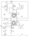
图9A是根据实施例的具有用于结合另一设备实现电感信号传送系统的部件的插接站(或其他附件设备)的简化框图。9A is a simplified block diagram of a docking station (or other accessory device) with components for implementing an inductive signal transfer system in conjunction with another device, according to an embodiment.
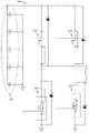
图9B是示意了在实施例下如图9A所描述的插接站的输出电路的合适电路配置的电路级图。Figure 9B is a circuit level diagram illustrating a suitable circuit configuration of an output circuit of a docking station as described in Figure 9A, under an embodiment.
图9C是描绘了在实施例下插接部上的电感接收机的合适电路配置的电路级图。9C is a circuit level diagram depicting a suitable circuit configuration for an inductive receiver on an embodiment lower receptacle.
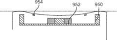
图9D和图9E示意了在另一实施例下用在一个或两个设备上的线圈组件或子组件。Figures 9D and 9E illustrate coil assemblies or subassemblies used on one or both devices under another embodiment.
图9F示意了在另一实施例下将插接部和移动计算设备进行电感耦合的可替换实施例。Figure 9F illustrates an alternative embodiment of inductively coupling the dock and the mobile computing device under another embodiment.
图10示意了在实施例下为了实现高效和安全的电感信令环境而在两个计算设备上实现的过程或方法。Figure 10 illustrates a process or method implemented on two computing devices to achieve an efficient and secure inductive signaling environment under an embodiment.
图11示意了根据实施例的在受控协议或过程下使相应的电源和功率接收设备能够彼此电感链接时在这两个设备上执行的步骤。Fig. 11 illustrates the steps performed on respective power source and power receiving devices when enabling inductive linking of the two devices with each other under a controlled protocol or process, according to an embodiment.
图12是在实施例下电源设备的操作状态的状态图。Figure 12 is a state diagram of operating states of a power supply device, under an embodiment.
图13示意了根据这里描述的实施例的可在设备之间交换的通信分组。Figure 13 illustrates communication packets that may be exchanged between devices according to embodiments described herein.
图14示意了在实施例下以二进制形式解释的各种电感信号调制。Figure 14 illustrates various inductive signal modulations explained in binary form under an embodiment.
图15示意了在实施例下其中可选择移动计算设备的定向以影响由一个或两个插接设备引起的操作或功能的方法。Figure 15 illustrates a method, under an embodiment, in which the orientation of a mobile computing device can be selected to affect the operation or functionality caused by one or both docked devices.
图16A示意了在实施例下可具有移动计算设备和/或插接部的结构表面特征的实施方式。Figure 16A illustrates an implementation of structural surface features that may have a mobile computing device and/or a dock under an embodiment.
图16B示意了在实施例下其中可以使用结构表面特征将移动计算设备机械地保持在插接部的平台上的实施方式。Figure 16B illustrates an implementation, under an embodiment, in which structured surface features may be used to mechanically retain the mobile computing device on the platform of the dock.
图16C示意了在实施例下其中可以使用插入式扣(insertive clasp)的集合将移动计算设备机械地保持在插接部的平台上的实施方式。Figure 16C illustrates an implementation, under an embodiment, in which a collection of insertive clasps may be used to mechanically hold the mobile computing device on the platform of the dock.
图17示意了在实施例下移动计算设备的背面的配置。Figure 17 illustrates the configuration of the back of a mobile computing device, under an embodiment.
图18示意了在实施例下包括磁体的装置(arrangement)的插接部的接收表面的俯视图。Figure 18 illustrates a top view of a receiving surface of a receptacle of an arrangement comprising magnets, under an embodiment.
图19示意了在另一实施例下具有磁体的装置的插接部的侧面横截面视图。Figure 19 illustrates a side cross-sectional view of the receptacle of a device with magnets under another embodiment.
图20示意了在实施例下使用磁扣而插接到插接部上的移动计算设备。Figure 20 illustrates a mobile computing device docked to a dock using a magnetic clasp, under an embodiment.
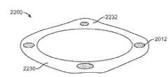
图21示意了根据实施例的用于磁扣的环形接口的透视图。Figure 21 illustrates a perspective view of a ring interface for a magnetic clasp according to an embodiment.
图22示意了根据实施例的具有机械凸起(proud)区域的环形接口的透视图。Figure 22 illustrates a perspective view of an annular interface with mechanically proud regions according to an embodiment.
图23示意了在实施例下可以用于磁扣的磁元件的实施例。Figure 23 illustrates an embodiment of a magnetic element that may be used in a magnetic clasp under an embodiment.
图24示意了在实施例下插接部和移动计算设备的横截面视图。Figure 24 illustrates a cross-sectional view of a dock and mobile computing device under an embodiment.
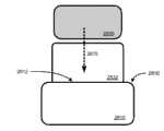
图25示意了其中移动计算设备可以耦合至背胶(sticky-back)附件设备的实施例。Figure 25 illustrates an embodiment in which a mobile computing device may be coupled to a sticky-back accessory device.
图26示意了根据实施例的电源设备。Fig. 26 illustrates a power supply device according to an embodiment.
图27示意了根据实施例的用于操作电源设备的方法。Fig. 27 illustrates a method for operating a power supply device according to an embodiment.
图28A示意了在实施例下保持和占用移动计算设备的电源设备的俯视横截面视图。Figure 28A illustrates a top cross-sectional view of a power supply device holding and engaging a mobile computing device, under an embodiment.
图28B示意了在实施例下保持移动计算设备的电源设备的前视图。Figure 28B illustrates a front view of a power supply device holding a mobile computing device, under an embodiment.
图28C示意了如图28B所示意的保持移动计算设备的电源设备的后视图。Figure 28C illustrates a rear view of the power supply device holding the mobile computing device as illustrated in Figure 28B.
图28D示意了在实施例中被插入到电源设备的车厢(carriage)中的移动计算设备。Figure 28D illustrates the mobile computing device plugged into the carriage of the power supply unit, in an embodiment.
图28E示意了在实施例中被插入到电源设备的车厢中的移动计算设备的另一视图。Figure 28E illustrates another view of the mobile computing device plugged into the compartment of the power supply unit, in an embodiment.
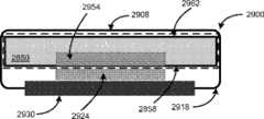
图29A是在实施例下包括移动计算设备的电源设备的侧面横截面视图。Figure 29A is a side cross-sectional view of a power supply device including a mobile computing device, under an embodiment.
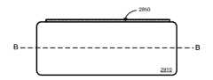
图29B示意了在实施例中包括图29A的移动计算设备的电源设备的前视图。Figure 29B illustrates a front view of a power supply device comprising the mobile computing device of Figure 29A, in an embodiment.
图29C示意了在实施例中包括图29A的移动计算设备的电源设备的后视图。Figure 29C illustrates a rear view of a power supply device comprising, in an embodiment, the mobile computing device of Figure 29A.
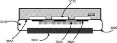
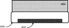
图30A是在实施例下包括移动计算设备的电源设备的侧面横截面视图。Figure 30A is a side cross-sectional view of a power supply device including a mobile computing device, under an embodiment.
图30B示意了在实施例中包括图30A的移动计算设备的电源设备的前视图。Figure 30B illustrates a front view of a power supply device comprising the mobile computing device of Figure 30A, in an embodiment.
图30C示意了在实施例中包括图30A的移动计算设备的电源设备的后视图。Figure 30C illustrates a rear view of a power supply device comprising, in an embodiment, the mobile computing device of Figure 30A.
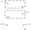
图31A示意了根据实施例的电源设备的前视图。Figure 31A illustrates a front view of a power supply device according to an embodiment.
图31B是包括图31A的移动计算设备的电源设备的横截面视图。31B is a cross-sectional view of a power supply device including the mobile computing device of FIG. 31A.
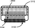
图32是在实施例中具有电感信号接口的电源设备的前等距视图。Figure 32 is a front isometric view of a power supply device with an inductive signal interface, in an embodiment.
图33是在实施例中包括电感信号接口的部件的隔离视图。Figure 33 is an isolated view of components including an inductive signal interface in an embodiment.
图34A示意了在实施例下电源设备的厢的前视图。Figure 34A illustrates a front view of a compartment for a power supply unit, under an embodiment.
图34B示意了图34B的电源设备的厢的后视图。Figure 34B illustrates a rear view of the compartment of the power supply unit of Figure 34B.
图35A示意了在实施例中可被插入到电源设备中的移动计算设备的可替换定向。Figure 35A illustrates an alternate orientation of a mobile computing device that may be plugged into a power supply unit in an embodiment.
图35B示意了在实施例下电源设备的可替换线圈配置。Figure 35B illustrates an alternative coil configuration for a power supply device, under an embodiment.
图35C示意了电源设备的线圈配置的另一实施例。Figure 35C illustrates another embodiment of a coil configuration for a power supply device.
图36示意了其中根据实施例的电源设备被配置为同时且电感接收功率并给另一设备供电的实施例。Figure 36 illustrates an embodiment in which a power supply device according to an embodiment is configured to simultaneously and inductively receive power and power another device.
图37示意了根据一个或多个实施例的将硬件和逻辑功能进行集成以关于移动计算设备的使用而实现对功能的执行的电源设备。Figure 37 illustrates a power supply device that integrates hardware and logic functions to enable execution of functions in connection with use of a mobile computing device, in accordance with one or more embodiments.
具体实施方式Detailed ways
这里描述的实施例使设备能够与另一设备进行电感链接,以便在这两个设备之间交换或杠杆(leverage)功能。一些实施例提供了在两个计算设备之间建立的电感链路。电感链路用于用信号发送(signal)功率和/或数据。如多个实施例所描述的,电感链路可以用于配置一个或所有电感链接的设备上的功能或操作。Embodiments described herein enable a device to be inductively linked with another device in order to exchange or leverage functionality between the two devices. Some embodiments provide for an inductive link established between two computing devices. Inductive links are used to signal power and/or data. As described in various embodiments, an inductive link may be used to configure a function or operation on one or all of the inductively linked devices.
这里描述的实施例提供了一种计算系统或包括该计算系统的一部分的设备。在实施例中,针对计算设备提供了插接站。该插接站可以由例如移动计算设备(例如蜂窝或无线电话/消息收发设备)使用。插接站包括外壳,该外壳包括接收和保持移动计算设备的接收顶表面。与外壳一起包括电感信号传送接口,以电感地用信号发送功率或数据中的至少一个给移动计算设备。插接站还提供了输出部件和处理资源。处理资源被配置为检测移动计算设备在接收表面上的布置。从移动计算设备接收数据,并且基于所接收的数据将输出用信号发送给输出部件。Embodiments described herein provide a computing system, or an apparatus comprising a portion thereof. In an embodiment, a docking station is provided for a computing device. The docking station may be used by, for example, a mobile computing device such as a cellular or wireless telephone/messaging device. The docking station includes a housing that includes a receiving top surface that receives and holds a mobile computing device. An inductive signal transfer interface is included with the housing to inductively signal at least one of power or data to the mobile computing device. The docking station also provides output components and processing resources. The processing resource is configured to detect the placement of the mobile computing device on the receiving surface. Data is received from the mobile computing device, and output is signaled to an output component based on the received data.
根据一些实施例,插接站是音频插接部,以便包括作为输出设备的扬声器。这里记载了插接站的其他示例。According to some embodiments, the docking station is an audio dock so as to include speakers as output devices. Additional examples of docking stations are documented here.
此外,这里描述的实施例包括计算机系统,该计算机系统包括彼此电感链接的第一计算设备和第二计算设备。两个设备之一电感地用信号发送标识符给其他设备。在接收到标识符时,该其他设备配置一个或多个操作。基于用信号发送的标识符来选择或另外配置操作。Additionally, embodiments described herein include a computer system that includes a first computing device and a second computing device that are inductively linked to each other. One of the two devices inductively signals the identifier to the other device. Upon receipt of the identifier, the other device configures one or more operations. An operation is selected or otherwise configured based on the signaled identifier.
根据一个实施例,移动计算设备(“MCD”)和插接站(“插接部”)单独地配备有在不使用连接器的情况下使充电/功率信号能够从插接部传送至MCD的特征和部件。作为附加或替换,当相对于插接部保持(即,“插接”)MCD时,插接部和/或MCD可以与该其他设备交换数据信号或者向该其他设备发送数据信号。According to one embodiment, the mobile computing device ("MCD") and the docking station ("dock") are individually equipped with features that enable charging/power signals to be passed from the dock to the MCD without the use of a connector and components. Additionally or alternatively, when the MCD is held (ie, "docked") relative to the receptacle, the receptacle and/or the MCD may exchange data signals with or send data signals to the other device.
可以使用编程元件(programmatic element)来实现这里描述的一些实施例,编程元件通常被称作模块或部件,尽管也可以使用其他名称。这种编程元件可以包括程序、子例程、程序的部分、或者能够执行一个或多个所声明的任务或功能的软件部件或硬件部件。如这里所使用,模块或部件可以存在于硬件部件上而与其他模块/部件无关,或者模块/部件可以是其他模块/部件、程序或机器的共享元件或过程。模块或部件可以驻留于一个机器上(例如客户端上或服务器上),或者模块/部件可以分布在多个机器当中(例如多个客户端上或服务器机器上)。所描述的任何系统可以整体或部分地实现在服务器上,或者被实现为网络服务的一部分。可替换地,例如这里描述的系统可以整体或部分地实现在本地计算机或终端上。在任一种情况下,本申请中提供的系统的实施方式可能需要使用存储器、处理器和网络资源(包括数据端口和数据线路(光、电等等)),除非另有声明。Some embodiments described herein may be implemented using programmatic elements, often referred to as modules or components, although other names may be used. Such programming elements may include programs, subroutines, portions of programs, or software components or hardware components capable of performing one or more stated tasks or functions. As used herein, a module or component may exist on a hardware component independently of other modules/components, or a module/component may be a shared element or process of other modules/components, programs or machines. A module or component may reside on one machine (eg, on a client or server), or a module/component may be distributed among multiple machines (eg, on multiple client or server machines). Any of the systems described may be implemented in whole or in part on a server, or as part of a web service. Alternatively, systems such as those described herein may be implemented in whole or in part on a local computer or terminal. In either case, implementation of the systems provided in this application may require the use of memory, processors, and network resources (including data ports and data lines (optical, electrical, etc.)) unless otherwise stated.
这里描述的一些实施例可能一般需要使用包括处理和存储器资源的计算机。例如,这里描述的系统可以实现在服务器或网络服务上。这些服务器可以相连接并被用户通过网络(例如互联网)或通过网络的组合(例如蜂窝网络和互联网)来使用。可替换地,这里描述的一个或多个实施例可以整体或部分地本地实现在计算机器(例如台式电脑、蜂窝电话、个人数字助理或膝上型计算机)上。因此,存储器、处理和网络资源均可以是关于这里描述的任何实施例的建立、使用或执行(与任何方法的执行或任何系统的实现一起包括)而使用的。Some of the embodiments described herein may generally require the use of computers including processing and memory resources. For example, the systems described herein can be implemented on a server or web service. These servers may be connected to and used by users through a network (eg, the Internet) or through a combination of networks (eg, a cellular network and the Internet). Alternatively, one or more embodiments described herein may be implemented in whole or in part locally on a computing machine such as a desktop computer, cell phone, personal digital assistant, or laptop computer. Accordingly, memory, processing, and network resources may all be utilized in connection with the establishment, use, or execution of any embodiment described herein, including with the execution of any method or implementation of any system.
此外,这里描述的一些实施例可以是通过使用一个或多个处理器可执行的指令来实现的。这些指令可以是在计算机可读介质上承载的。以下各图中所示的机器提供了在其上可承载和/或执行用于实现本发明实施例的指令的处理资源和计算机可读介质的示例。具体地,在本发明实施例中示出的多个机器包括处理器以及用于保持数据和指令的各种形式的存储器。计算机可读介质的示例包括永久内存存储设备,例如个人计算机或服务器上的硬盘驱动器。计算机存储介质的其他示例包括便携式存储单元(例如CD或DVD单元)、闪存(例如在许多蜂窝电话和个人数字助理(PDA)上承载)以及磁存储器。计算机、终端、网络使能设备(例如,诸如蜂窝电话之类的移动设备)是利用处理器、存储器、以及计算机可读介质上存储的指令的机器和设备的所有示例。Additionally, some of the embodiments described herein may be implemented using one or more processor-executable instructions. These instructions may be carried on a computer readable medium. The machines shown in the following figures provide examples of processing resources and computer-readable media on which instructions for implementing embodiments of the invention may be carried and/or executed. In particular, the various machines shown in the embodiments of the invention include processors and various forms of memory for holding data and instructions. Examples of computer readable media include persistent memory storage devices such as hard drives on a personal computer or server. Other examples of computer storage media include portable storage units such as CD or DVD units, flash memory (such as carried on many cell phones and personal digital assistants (PDAs), and magnetic memory. Computers, terminals, network-enabled devices (eg, mobile devices such as cellular telephones) are all examples of machines and devices that utilize processors, memory, and instructions stored on computer-readable media.
概述overview
图1A是示意了根据实施例的两个计算设备的示意图,可以使这两个计算设备相接触,以便用于使一个设备能够将功率和/或数据信号提供给其他设备的目的。这里描述的多个实施例(包括例如图1所述的实施例)将MCD和插接部称作彼此接触以在不使用传统插入式或机械耦合连接器的情况下进行功率/数据传送目的的两个设备。然而,在这里描述的实施例中可以使用不同类型的设备(例如,便携式设备和附件设备)。在这里提供的许多示例中,电感耦合的两个设备与移动计算设备(也被称作MCD)和附件设备(具体地,插接部或插接站)相对应。然而,还可以使用其他类型的设备来实现实施例。在一个实施方式中,MCD是具有蜂窝数据和电话能力的多用途设备,而附件设备对应于例如插接站(用于通信和电源)、背胶(或背载)附件、投光器、音箱或头戴式耳机站。作为蜂窝电话/数据能力的附加或替换,MCD可以包括例如用作以下各项的功能:媒体播放器、摄像机或录像机、全球定位单元、超移动个人计算机、膝上型计算机或多用途计算设备。这里描述了多个其他示例和实施方式,包括其中三个或更多个设备通过一个或多个无连接器的连接而互连的实施例。1A is a schematic diagram illustrating two computing devices that may be brought into contact for the purpose of enabling one device to provide power and/or data signals to the other device, according to an embodiment. Various embodiments described herein (including, for example, the embodiment described in FIG. 1 ) refer to the MCD and the receptacle as being in contact with each other for power/data transfer purposes without the use of conventional plug-in or mechanically coupled connectors. two devices. However, different types of devices (eg, portable devices and accessory devices) can be used in the embodiments described herein. In many of the examples provided herein, the inductively coupled two devices correspond to a mobile computing device (also referred to as an MCD) and an accessory device (specifically, a dock or docking station). However, other types of devices may also be used to implement embodiments. In one embodiment, the MCD is a multipurpose device with cellular data and telephony capabilities, while the accessory device corresponds to, for example, a docking station (for communication and power), an adhesive-backed (or back-mounted) accessory, a light projector, a speaker, or a headset headphone stand. In addition to or instead of cellular phone/data capabilities, the MCD may include functionality, for example, as a media player, video camera or video recorder, global positioning unit, ultra-mobile personal computer, laptop computer, or multipurpose computing device. A number of other examples and implementations are described herein, including embodiments in which three or more devices are interconnected by one or more connectorless connections.
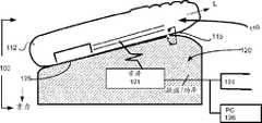
相应地,系统100包括由插接部120支撑或另外保持的MCD 110。其中支撑MCD 110的方式可以变化。此外,如利用一个或多个实施例所描述的,用户可以改变MCD在插接站上的定向,用于配置一个或两个设备的操作或行为的目的。根据所示的实施例的定向,在插接部120上在部分直立的位置处沿其长度轴(L)支撑MCD 110。这种定向可以与“肖像(portrait)”位置相对应。在其中可替换定向可能的实施例中,一个或多个“风景”位置或者肖像与风景之间的位置是可能的。Accordingly,
根据实施例,插接部120利用物理支撑结构(未示出)(例如架子、平台、钩或机械保持特征),将MCD 110保持在插接或配对位置处。在另一实施例中,针对插接部120和/或MCD 110,可以包括或提供磁扣,以牢固MCD相对于插接部的保持。全部内容以参考方式并入此处的优先权美国专利申请No. 12/239,656详述了使用磁扣和铁质(或其他)材料,以便将MCD 110物理保持在与插接部120插接的位置处。According to an embodiment, the
插接部120可以包括用于生成功率和/或数据信号并将其延伸至MCD 110的资源121。例如,插接部120可以与功率出口124或另一计算机126(例如,台式计算机)配对以延伸功率和/或数据信号。资源121可以包括电路或硬件,例如AC/DC转换器和调节器。为了使插接部120能够从个人计算机或其他计算站接收电功率,一个实施方式提供了包括物理连接器端口(例如由通用串行总线(USB)连接器提供)的插接部120。此外,插接部120可以包括数据获取能力,该数据获取能力是通过计算机126的连接器端口、无线端口(例如,蜂窝、WiMax连接、蓝牙)、互联网端口和介质馈线来提供的(例如,通过电视调谐器和线缆来提供的)。
如图1的实施例所示,MCD 110具有厚度为(t)的外壳套(housing shell)112。外壳套112可以用于保持MCD 110的内部部件,例如电路板、处理器、存储器或者显示组件的部件。MCD 110可以被构造为使得外壳套112的主面115(例如,背面板)依靠在插接部120的接收表面125上。As shown in the embodiment of FIG. 1 , the
这里描述的实施例提供了一种用于在不使用电导体的情况下短距离传送电功率的系统和技术。在一个实施例中,MCD 110和插接部120是电感耦合的。MCD 110可以物理地置于插接部120上,以将功率和数据信号中的一个或两个电感耦合。在其他实施例中,MCD 110和插接部120可以被放置为彼此接近而无物理接触。Embodiments described herein provide a system and technique for transmitting electrical power over short distances without the use of electrical conductors. In one embodiment,
作为替换地或附加地,MCD可以配备有定向传感器(例如加速计),以便供设备检测其自身关于重力的定向。MCD 110可以包括基于其在插接部120上的定向(例如风景或肖像)而实现或自动执行的功能。在一个实施例中,该设备将其定向传送至插接部(例如,以电感方式或通过无线(RF)通信介质),使得插接部120可以便于或执行与MCD在给定的定向上执行的操作一致的功能。为了使MCD的加速计(或其他传感器)能够检测其自身位置,由插接部120提供的支撑的角度可以使得传感器可操作。例如,这里描述的一些实施例采用加速计,在这种情况下,与适当支撑MCD 110的水平面的角度至少为22.5度。Alternatively or additionally, the MCD may be equipped with an orientation sensor (eg an accelerometer) for the device to detect its own orientation with respect to gravity.
可替换外壳实施方式和配置Alternative Housing Implementations and Configurations
尽管在别处描述的许多示例具体记载了其中在作为移动计算设备和插接部(或插接站)的两个设备之间发生电感充电的实施方式,但是所记载的实施例可以是在被更一般地记载为电源或功率接收设备的设备之间等同地应用的。一些实施例认识到,电感充电可以由其他类型的计算设备执行或利用其他类型的计算设备而执行。例如,不是使用在某可操作决定中支撑移动计算设备的插接站,而是附件设备可以具有使其能够在设备上承载的可替换形状因子。Although many of the examples described elsewhere specifically recite implementations in which inductive charging occurs between two devices that are a mobile computing device and a dock (or docking station), the recited embodiments may be described more generally Equivalents apply between devices described as power supply or power receiving devices. Some embodiments recognize that inductive charging may be performed by or with other types of computing devices. For example, rather than using a docking station that supports the mobile computing device in some operational decision, the accessory device may have an alternative form factor that enables it to be carried on the device.
同样地,移动计算设备可以承载作为附件特征的电感充电能力。例如,图1B示意了可被覆盖到移动计算设备110上的现有外壳段190上或取代现有外壳段190而组装的外壳段180。外壳段180包括用于实现与另一设备的电感信号传送的信号处理机资源182(如在本申请中的图7A的实施例和其他位置处所描述的)。外壳段180可以是与MCD 110分离地购买的,并可以被用户组装到MCD上以使MCD能够具有电感充电(功率接收)、电感功率信令和/或电感数据传送的能力。在一个实施例中,外壳段180是MCD的电池盖。数据和功率总线184可以将外壳段的电感信令资源182与计算设备的电池和其他电子部件互连。Likewise, mobile computing devices may carry inductive charging capabilities as an accessory feature. For example, FIG. 1B illustrates a
在其中使用磁扣将MCD 110耦合至插接部的实施例中,外壳段180的外表面可以包括设备110与插接部或附件磁耦合所需的一些或所有铁质材料(或磁体)。作为替换,可以在MCD的外壳的除段180外的其他部分上提供铁质材料。为了这里描述的应用的目的,对具有电感信号接收/发送能力的移动计算设备的参考可以包括具有制造或销售后部分地装饰或替换的其外壳的设备。In embodiments where a magnetic clasp is used to couple the
电感信号路径Inductive Signal Path
图2A是MCD 210和插接部220的简化框图,其中,一个或两个设备被配置为在具有电感信号路径部分的信号路径上对信号进行传送,以便形成部分电感信号路径。根据实施例,MCD 210可以被放置为与插接部220接触,例如以利用其他实施例所述(例如图1所述)的方式。结果是:设备外面208(例如,后面)与插接部的接收表面228接触。可替换地,可以使这两个设备很接近,但不必接触,以便发生电感信号通信。尽管MCD 210和插接部220的外表面208、228分别可以由于插接部对MCD的保持而接触,但是不进行接触以在这些设备之间导电传送信号。更确切地,插接部220上的信号源224(例如,功率入口)可以生成通过磁线圈226或其他电感机构而变换为磁场的信号228(例如功率)。可以在MCD 210上提供对应的线圈214或电感接收部件,以将信号228变换为电信号216。电信号216可以由各种电路元件和部件处理,以便给MCD 210的部件通电和/或给设备210的电池模块219充电。2A is a simplified block diagram of an
图2B示意了使用在插接部220和MCD 210上提供的磁/电感和导电元件的组合而从插接部220到MCD 210延伸或在插接部220与MCD 210之间延伸的电感信号路径250。在插接部上,信号路径250包括电流相位252和电感(或磁场)相位254。电感相位254使用磁场来承载相应外壳的边界上的信号。因此,在设备210上,信号路径250包括电感相位254后面紧接着电流相位256。相反路径也是可能的,例如,在MCD将功率和/或数据供给至插接站或另一附件设备的情况下。2B illustrates an inductive signal path extending from or between receptacle 220 to
电感线圈布置Inductor Coil Arrangement
可以通过使用在要耦合以发送或接收功率和/或数据信号的每个设备上提供的线圈来实现功率和/或数据信号的电感传送。各种线圈配置是可能的,以实现功率和/或数据的单向或双向传送。Inductive transfer of power and/or data signals may be accomplished by using coils provided on each device to be coupled to transmit or receive power and/or data signals. Various coil configurations are possible to enable unidirectional or bidirectional transfer of power and/or data.
图3A至图3C示意了在不同实施例或变型下用于电感信号传送的不同线圈分布实施方式。具体地,图3A示意了包括两个线圈(每个设备上一个)的系统或子系统。这两个线圈302、304可以用于在这两个设备之间交换的一个信号301中传送功率和/或数据。此外,功率或数据的传送可以是双向的。3A to 3C illustrate different implementations of coil distribution for inductive signal transmission under different embodiments or variants. In particular, Figure 3A illustrates a system or subsystem comprising two coils, one on each device. The two
图3B示意了三线圈实施方式,其中,两个设备之一(例如插接部220)包括两个线圈312、314,并且其他设备(例如,MCD 210)包括仅一个线圈316。该实施例可以提供以下优势:在实现分离的数据和功率交换的同时,减小从MCD所需的重量或大小。在一个实施例中,MCD 210的线圈316从插接部上的一个线圈312接收功率311,并从其他线圈314接收数据313。可选地,功率311或数据313信号可以是双向的,这意味着MCD 210上的线圈316可以将信号传送回到插接部220。在一个实施方式中,MCD 210上的线圈用信号发送数据给插接部220上的独立数据线圈。FIG. 3B illustrates a three-coil embodiment, where one of the two devices (eg, interposer 220 ) includes two
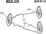
图3C示意了其中插接部320和MCD 310中的每一个包括两个线圈的另一实施方式。具体地,插接部320上的功率和数据线圈322、324可以将功率321和数据323信号传送至MCD 310上的相应线圈332、334。在实施例中,功率和数据通信是双向的。FIG. 3C illustrates another embodiment in which each of the interposer 320 and the
使用电感信号路径的计算机系统Computer systems using inductive signal paths
图4示意了在实施例下提供功率和/或数据信号的电感传送的计算系统的简化框图。根据这里描述的多个实施例,计算系统400包括被构造为实现电感信号传送交换的MCD 410和插接部420。在实施例中,插接部420包括中央处理器424、功率子系统422和通信子系统426。MCD 410包括功率子系统412、信号处理器414和通信子系统416。此外,MCD 410(以及可选地,插接部420)包括多个其他部件,例如,用于实现应用执行、蜂窝和数据通信以及作为MCD 410的使用的一部分的多个其他功能的中央处理器和存储器资源。Figure 4 illustrates a simplified block diagram of a computing system providing inductive transfer of power and/or data signals, under an embodiment. According to various embodiments described herein, computing system 400 includes MCD 410 and receptacle 420 configured to enable inductive signaling exchanges. In an embodiment, receptacle 420 includes a central processing unit 424 , a power subsystem 422 and a communication subsystem 426 . MCD 410 includes power subsystem 412, signal processor 414, and communication subsystem 416. In addition, the MCD 410 (and optionally the socket 420) includes a number of other components, such as a central processing unit for application execution, cellular and data communications, and a number of other functions as part of the use of the MCD 410 and memory resources.
在插接部420上,功率子系统422包括与持续电源421的连接,例如墙上插座。此外,功率子系统422包括以下部件:这些部件用于将来自电源的信号转换和调节为适于使用例如电感介质传送的形式。此外,功率子系统422包括用于将源自电源421的电信号转换为电感信号的一个或多个线圈。通信子系统426可以包括用于向其他设备接收和发送数据的无线或有线端口,这些其他设备包括其他计算机或数据源(例如,来自其他设备(例如机顶盒)的介质馈线)或介质输出设备。在实施例中,通信子系统426还实现对通过在这两个设备之间延伸的电感信号路径之一而传送的数据的电感数据处理。如所提及的,可以通过对电感功率信号进行调制或使用分离的数据信号路径来传送这种数据。On receptacle 420 , a power subsystem 422 includes a connection to a continuous power source 421 , such as a wall outlet. Additionally, power subsystem 422 includes components for converting and conditioning signals from the power supply into a form suitable for transmission using, for example, inductive media. Additionally, power subsystem 422 includes one or more coils for converting electrical signals originating from power supply 421 into inductive signals. Communication subsystem 426 may include wireless or wired ports for receiving and sending data to other devices, including other computers or data sources (eg, media feed lines from other devices such as set-top boxes) or media output devices. In an embodiment, the communications subsystem 426 also enables inductive data processing of data communicated over one of the inductive signal paths extending between the two devices. As mentioned, such data may be communicated by modulating the inductive power signal or using a separate data signal path.
插接部420的中央处理器424可以被配置为处理来自通信子系统426的输入数据信号,不论是来自其他源还是来自MCD 410。此外,中央处理器424可以控制向外传送至其他资源或MCD 410(使用电感信号路径)的数据。Central processor 424 of jack 420 may be configured to process incoming data signals from communications subsystem 426, whether from other sources or from MCD 410. In addition, the central processing unit 424 may control data transfer out to other resources or to the MCD 410 (using an inductive signal path).
在MCD 410上,实施例提供了:功率子系统412从插接部420接收输入功率信号408,并以修改或调节的形式将功率信号分发至其他部件或电池以供再充电。以单向的方式通过从插接部420至MCD 410的电感路径用信号发送功率信号408。通信子系统416被配置为与插接部420进行通信,以接收和/或发送数据信号409。一个实施例提供了:通信子系统416可以包括用于对在功率信号上承载的数据进行解调的资源。具体地,通信子系统416可以使用其资源来实现一个或多个协议,例如:(i)用于调节在接收设备上对电流/电压信息(例如使用级别)进行传送的数据交换的功率的电感传送的协议;(ii)用于从功率信号408的调制的特性中检索并使用证书信息(例如,用于建立后续无线通信的预备数据)的证书协议。一个或两个协议还可以提供通信子系统416使用由功率信号408传送的证书信息和/或其他数据来切换至例如标准化无线通信介质(例如蓝牙)。此外,另一实施例可以提供使通信子系统416能够生成调制后的功率或其他信号,以传送至插接部420或其他设备。例如,如图3B所示,可以在插接部上使用两个线圈,包括对功率和数据进行传送的一个线圈和从MCD 410接收数据的另一线圈。通信子系统416可以执行以下功能:从调制的数据信号中检索数据并将数据向外传送至MCD 410上的数据接收线圈。On MCD 410, embodiments provide that power subsystem 412 receives input power signal 408 from jack 420 and distributes the power signal in a modified or conditioned form to other components or batteries for recharging. The power signal 408 is signaled through the inductive path from the receptacle 420 to the MCD 410 in a unidirectional manner. Communication subsystem 416 is configured to communicate with receptacle 420 to receive and/or transmit data signal 409 . One embodiment provides that the communication subsystem 416 may include resources for demodulating data carried on the power signal. Specifically, communication subsystem 416 may use its resources to implement one or more protocols, such as: (i) an inductance for regulating the power of data exchanges communicating current/voltage information (e.g., usage levels) at a receiving device The protocol transmitted; (ii) the credential protocol for retrieving and using credential information (eg, preliminary data for establishing subsequent wireless communications) from the modulated characteristics of the power signal 408 . One or both protocols may also provide for communication subsystem 416 to use credential information and/or other data conveyed by power signal 408 to switch to, for example, a standardized wireless communication medium (eg, Bluetooth). Additionally, another embodiment may provide for enabling communications subsystem 416 to generate modulated power or other signals for transmission to receptacle 420 or other devices. For example, as shown in FIG. 3B, two coils may be used on the receptacle, including one coil to transmit power and data and another coil to receive data from the MCD 410. The communication subsystem 416 may perform the following functions: retrieve data from the modulated data signal and transmit the data out to a data receiving coil on the MCD 410.
如利用一些其他实施例所述,还通过对功率信号进行调制将数据信号409与功率信号408进行组合。在一个实施方式中,插接部420用信号发送具有功率信号408的数据409,作为建立不同无线通信关系的预备步骤。在另一实施例中,可以与功率信号分离地向MCD或从MCD传送数据信号409。As described with some other embodiments, the data signal 409 is also combined with the power signal 408 by modulating the power signal. In one embodiment, the receptacle 420 signals the data 409 with the power signal 408 as a preliminary step to establishing a different wireless communication relationship. In another embodiment, the data signal 409 may be transmitted to or from the MCD separately from the power signal.
设备框图Device Block Diagram
图5是根据实施例的MCD的简化框图。MCD 500可以被配置为包括利用其他实施例所述的任何功能或能力,包括使用导电或电感信号路径接收电信号(功率和/或数据)的能力。因此,如利用其他实施例所述,MCD 500可以对应于例如“智能电话”、移动伴侣、媒体播放器、数码摄像机或GPS单元(或者可作为所描述的许多设备而执行的多功能设备)。Figure 5 is a simplified block diagram of an MCD, according to an embodiment.
更具体地,一个或多个实施例提供了:MCD 500可以对应于移动电话/数据消息收发计算设备,例如蜂窝电话或具有语音电话能力的移动设备(有时被称作“智能电话”)。例如所描述的计算设备可以足够小以适配于一只手,同时结合其他应用提供蜂窝电话特征,这些其他应用例如是消息收发、网页浏览、媒体回放、个人信息管理(例如,联系人记录管理、日程表应用、任务列表)、图像或视频/媒体捕获和其他功能。可从MCD 500提供的功能的其他示例包括音频和/或视频回放或全球定位服务(GPS),作为首要或使能功能。MCD 500可以具有多种类型的输入机制和用户界面特征,例如键盘或键区、多方向或导航按钮、应用或动作按钮、以及接触或触摸敏感显示屏或按钮。在数据消息收发/通信设备的情况下,可执行的具体类型的消息收发或通信包括用于电子邮件应用、短消息服务(SMS)、多媒体消息服务(MMS)和专有语音交换应用(例如SKYPE)的消息收发。此外,MCD 500可以对应于多种其他类型的计算设备,例如笔记本计算机、超移动计算机或个人数字助理。More specifically, one or more embodiments provide that
根据实施例,MCD 500包括一个或多个处理器510、存储器资源520、显示组件528、一个或多个通信端口530和电源模块540。在实施例中,MCD 500包括信号处理机资源550(或模块),信号处理机资源550包括用于使用电感通信介质接受和/或发送功率或数据信号的硬件和逻辑。作为另一选项,MCD 500包括一个或多个检测器560(或传感器),用于在设备插接至附件设备时检测MCD 500的定向或位置。According to an embodiment, the
处理器510可以包括信号处理资源550或与信号处理资源550进行通信,以实现用于实现对信号的电感接收或发送的一些或所有信号处理能力。通信端口530可以包括无线或有线端口。可以通过例如局部无线通信协议(例如,由蓝牙标准、无线保真(802.11(b)或(g))提供)来实现无线通信端口。无线通信端口还可以通过蜂窝网络进行通信。更具体地,MCD 500可以包括用于提供特定类型的无线连接以执行任何一种或多种类型的无线操作目的的一个或多个无线通信端口。例如,通信端口530可以包括或对应于:(i)用于发送和接收蜂窝语音/数据的广域网(WAN)无线电模块;(ii)局部无线通信端口,例如蓝牙或无线USB;(iii)红外端口;(iv)全球定位系统无线电;和/或(v)WiMAX无线电。Processor 510 may include or be in communication with
例如,存储器资源520可以包括闪存、随机存取存储器和/或永久存储器(即ROM)。存储器资源520包括用于实现(例如在任何所述实施例中提供的)功能和程序动作的指令和数据。可选地,存储器资源520可以承载记录的数据库或数据存储器,其包含与主计算机同步或通信的活动数据项目(例如以上所述)和/或在这种数据项目上实现保存数据项目的动作。For example,
根据实施例,信号处理机资源550包括用于向和/或从插接部接收或发送功率信号和/或数据信号(被调制或组合为一个信号)的硬件。在上述各个实施例中详述了信号处理器资源550的用于实现电感信号路径的部件和元件的附加细节。在一个实施例中,信号处理器资源550被配置为接收功率信号,用于给MCD 500的其他部件(例如,显示组件528)通电或给电源模块540的电池再充电的目的。在一个实施方式中,可以使用与MCD 500的中央处理器分离的电路和部件来处理输入的功率信号。因此,处理器510可以包括多于一个单元或资源。在一个实施方式中,例如,MCD 500包括信号处理器(其可以与信号处理机550合并)和中央处理单元(CPU)。According to an embodiment, the
如其他地方所述,实施例提供了:MCD被配置为使用信号处理机资源550来传送和/或接收实现设备之间的后续通信的一些数据。该数据可以包括证书数据552,证书数据552使用例如经由局部无线通信端口530之一的局部无线通信链路来实现后续无线通信。可以将证书数据552存储在存储器资源的一部分内,并使其对处理资源来说可用,以与由信号处理机资源550执行的功能一起包括或使用。在一个实施例中,信号处理资源550能够通过调制的功率信号来对证书数据中的至少一些进行电感传送。作为附加或变型,信号处理资源550能够识别或使用从插接部电感传送的证书数据552,以标识插接部并与插接部配成对。As described elsewhere, embodiments provide that the MCD is configured to use the
在一个实施例中,以独立检测MCD 500的定向的传感器的形式提供检测器560。例如,检测器560可以对应于检测MCD 500在任何给定时刻处的定向的加速计或垂直位置传感器。在另一实施例中,检测器560感测数据或信号或将其传送至定位在插接部的暴露表面上的电气或导电(或电感)板。因此,可以通过确定哪些检测器560和/或传感器或导电板在这两个设备插接时相接触来检测MCD的位置。In one embodiment, the
标识MCD 500在插接时的定向的信息可以影响MCD和/或其部件的各种操作或模式/状态。检测器560可以用信号发送定向信息562至MCD 的处理器510或传送至MCD 的处理器510。在一个实施方式中,例如,处理器510被配置为使用定向信息562用信号发送显示状态529给显示组件528。例如,响应于信号,可以在肖像和风景模式之间切换显示组件528。Information identifying the orientation of the
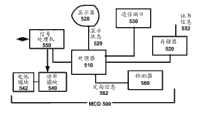
图6是在实施例下插接部的简化框图。插接部600可以对应于利用这里的其他实施例所描述的任何插接部。具体地,所描述的插接部可以用于实现(取决于实施例)电感信号路径,该电感信号路径用于与MCD传送功率和数据,例如图6所述。在实施例中,插接部600包括处理资源610、信号处理机620、存储器资源630和电源(power resource)640。插接部600还可以包括一个或多个通信端口,该一个或多个通信端口包括无线通信端口642和/或一个或多个有线通信端口644。Figure 6 is a simplified block diagram of a socket under an embodiment. The
处理资源610实现智能操作,例如认证MCD 500或与MCD 500配成对(参见图5)(例如通过无线链路)和/或数据共享/同步操作(与MCD 500)。在一个变型中,插接部600还能够与计算资源(例如其他设备或计算机)进行对接,以实现MCD 500与第三设备之间或者插接部与第三设备之间的同步或数据共享操作。在实施例中,处理资源610对应于或包括信号处理器,该信号处理器能够通过功率信号中的调制来接收或发送数据。
信号处理机620包括用于实现与驻留于MCD的面板或外壳内的对应元件的电感耦合的电路和元件。信号处理机620可以包括用于发送和/或接收功率或数据的一个或多个线圈。如上所述,可选地,可以以对数据进行承载或传送的方式对通过磁线圈而传送的功率信号进行调制。因此,信号处理机620可以使用在电感信号路径上承载的功率信号来传送或接收数据。
电源640处理通过标准出口而接收的功率。作为可替换地或附加地,电源640可以从另一计算设备提取功率。此外,电源640可以包括给插接部和其他设备提供功率的电池。
可以以标准化端口(例如,由蓝牙或无线USB标准定义)的形式提供无线通信端口642。物理端口也可以是标准化的(例如,由USB或固线标准提供)。The
可选地,插接部600包括可检测MCD在插接位置处的定向的定向检测机构612。作为附加或可替换,定向检测机构612检测是否存在(即,插接有)MCD。如其他实施例所描述,定向检测机构612可以使用指示MCD在插接位置处的定向的信息来执行或配置状态或模式或操作。可替换地,插接部600可以将定向信息传送至MCD。Optionally, the
在插接部可执行的可能功能当中,插接部可以发送或接收与MCD的无线通信611。这种通信可以完成各种任务或操作,包括:(i)数据文件或记录661的同步或通信(例如,对联系人和电子邮件进行同步);(ii)使用证书信息663和设备通信662来与MCD建立配对关系以用于后续操作;(iii)在MCD与连接至插接部的第三计算设备之间建立配对关系(例如,实现与所附着的个人计算机的蓝牙或有线通信);(iv)通过将通信662转发至第三计算机(例如,个人计算机或膝上型计算机),用作与另一设备(例如,显示屏的电视)的贯通或数据接口;和/或(v)交换数据以共享或提供资源或扩展MCD的功能(例如,通过将音频路由至与插接部相连接的扬声器,实现驻留于设备上的媒体数据665的回放)。Among the possible functions that the dock can perform, the dock can send or receive
插接部600可服务的一个主要目的在于:使用通过信号处理机620而传送的功率来给MCD再充电或通电。此外,实施例提供了:插接部600检测MCD的定向,并且然后将定向信息传送至MCD。One main purpose that the
尽管图6的实施例描述了与插接部相对应的附件设备,但是应当清楚,其他形式的附件设备可以包括类似的部件或功能。例如,可以以“背胶”设备的形式提供附件设备。例如,这种设备可以使用信号处理机620来导电或电感接收功率或数据。这种设备还可以执行与MCD的无线通信,以对记录进行同步,执行媒体回放和/或另外共享其他形式的数据(例如,提供GPS数据、接收图像等)。Although the embodiment of FIG. 6 depicts accessory equipment corresponding to a receptacle, it should be clear that other forms of accessory equipment may include similar components or functionality. For example, accessory devices may be provided in the form of "adhesive-backed" devices. For example, such a device may use
因此,对于所记载的示例,实施例提供了:MCD 500(参见图6)可以被配置为:(i)从附件设备(例如插接部600)接收功率;和/或(ii)使用局部无线通信端口来执行与附件设备(即,插接部600或其他设备)的无线通信。附加地,MCD可以使用功率信号或无连接器的介质来交换并以程序方式执行认证或授权无线配对和通信的步骤中的至少一些。在例如附件设备需要功率的一些情况下,MCD可以使用电感信号传送来供电。Thus, for the documented example, embodiments provide that MCD 500 (see FIG. 6 ) can be configured to: (i) receive power from an accessory device (eg, dock 600); and/or (ii) use local wireless Communication port to perform wireless communication with an accessory device (ie,
MCD上的信号处理机Signal processor on MCD
图7A是根据实施例的具有用于结合另一设备(例如,如图6所述的插接站)实现电感信号传送系统的部件的移动计算设备(例如图5所述)的简化框图。在图7A中,示出了信号处理资源550,包括用于与另一设备电感接收和/或传送功率/数据的各个部件。更具体地,信号处理资源550包括形成对应电感信号路径的端子的一个或多个线圈722。此外,信号处理资源550包括通信电路728、电源电路726和用于使用电感信号路径处理输入和输出信号的信号处理器740(CPU或处理资源)。处理器740被编程为实现针对功率的受控使用和电感链路上的数据的交换的协议。更具体地,信号处理器740(i)实现可借以通过电感信号路径对数据进行传送和/或解释、部分地通过线圈722而使能数据的协议;以及(ii)控制接收/通信功率。为此,其可以使能处理输入信号路径的电源电路726。通过经由调节器732从线圈722接收到的电压711来给信号处理器740通电。在一个实施方式中,调节器电源732给处理器740供应3伏特。信号处理器740还监视电流(电流值744),以检测通过线圈722接收到的功率信号的电流电平。电源电路726在电源总线747上将功率信号748供给至设备电子装置770。这样,功率信号748给MCD 500(图5)的部件独立通电。功率信号748还可以给设备的电池再充电。7A is a simplified block diagram of a mobile computing device (eg, as described in FIG. 5 ) having components for implementing an inductive signal transfer system in conjunction with another device (eg, a docking station as described in FIG. 6 ), according to an embodiment. In FIG. 7A, a
根据一些实施例,信号处理器740在数据总线742上用信号发送数据749,以与设备的另一处理资源(如CPU)交换数据。该数据可以对应于例如证书信息或者与从插接站接收到的数据有关的信息(例如,对证书信息交换的确认)。According to some embodiments,
此外,MCD 500(图5)可以被配置为将用于检测外部对象(即,插接部)的检测器(例如传感器)组合用于检测与插接部有关的信息的机构。Additionally, the MCD 500 (FIG. 5) can be configured as a mechanism that combines a detector (eg, a sensor) for detecting an external object (ie, the receptacle) for detecting information related to the receptacle.
根据一个或多个实施例,电源电路726包括同步电桥730、调节器732、电流感测器734和输出钳位器(clamp)736。线圈722从插接部600(参见图6)或其他附件设备接收输入电感信号721。同步电桥730将未调节的DC信号输出至调节器732和电流感测器734。如上所述,一个实施方式提供了:调节器732是3伏调节器,以将3伏功率信号供给至信号处理器740。电流感测器734将电流值744用信号发送给处理器740,处理器740接通或关断输出钳位器736。更具体地,在所供给的电感信号721超过期望功率电平的时刻处,输出钳位器进行操作736(具有来自处理器740的使能信号737)以导通和钳断过电压。输出钳位器736可以充当电压调节器或“降压”(buck)转换器。这样,输出钳位器736确保输出(用于给设备500通电或给其电池再充电)被调节。因此,在输入电感信号721太高的时刻处,信号处理机可以将电压调节至设备电子装置。According to one or more embodiments, the power supply circuit 726 includes a
如上所述,可以对输入信号721进行调制以在功率传送时承载数据。通信电路728(其部分可以被分布或与处理器或其他位置集成)可以包括用于在给定的持续时间上检测输入信号721的信号调制的频移键控(FSK)检测器716。FSK调制仅是可针对该设备而实现的一种类型的调制。例如,检测器可以用于处理AM信号调制、相位调制、QAM、CDMA、极位置或各种其他形式的信号调制。这种FSK调制可以与这里记载的一个或多个协议一致。将从检测器检测到的输入数据717传送至处理器740。输入数据717可以包括协议数据(用于发起协议事件的序列以控制从插接部600供给至MCD 500的功率的数据)或者证书或使用率数据。处理器740可以通过数据总线742将一些数据从输入信号721传送至设备(例如,设备的CPU)。可以对其他数据进行处理以确定协议响应,或提供/使用反馈以调谐功率信号721的特性。处理器740可以使用AM调制(或者可替换地,FM调制)在电感信道上将数据用信号发送出。在一个实施例中,相同线圈722用于在MCD 500上发送出数据并接收进数据。更具体地,数据输出可以与以下协议数据相对应,该协议数据:(i)响应于协议事件,例如从插接部600传送的信号;(ii)提供反馈,包括电源信息(例如,需要多少功率)或用于实现对输入功率信号721的受控调节的其他数据。As described above, the input signal 721 may be modulated to carry data while power is transferred. Communications circuitry 728 (parts of which may be distributed or integrated with a processor or elsewhere) may include a frequency shift keying (FSK)
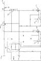
图7B是示意了图7A所示的系统的一部分的示例电路配置的电路级图。图7B中的电路元件包括输入/输出(I/O)端口751和752、晶体管二极管对753、754、755和756、运算放大器757和758、平滑电容器759、去耦合元件760、输出数据信号线路761、DC功率线路762。I/O端口751和752可以表示可电感耦合以接收和发送数据和功率的线圈。I/O端口751和752可以表示单个电感耦合线圈,例如图7A的线圈722。I/O端口751和752通过电感耦合来接收AC信号。所接收的AC信号包括功率分量和数据分量中的至少一个。使用由二极管753、754、755和756形成的同步电桥或整流器将所接收的AC信号的功率分量转换为DC功率信号。同步电桥与图7A的同步电桥730相对应。可替换地,可以使用半同步电桥。7B is a circuit-level diagram illustrating an example circuit configuration of a portion of the system shown in FIG. 7A. Circuit elements in FIG. 7B include input/output (I/O)
在晶体管二极管对753、754、755和756中的每一个中,晶体管(典型地,MOSFET)与二极管串联连接,以在二极管正向偏置时消除二极管上的电压降。在晶体管二极管对755和756中,晶体管的栅极分别由运算放大器757和758控制。运算放大器757被配置和耦合以输出电压电平,以便在晶体管二极管对755的二极管变为正向偏置时导通晶体管二极管对755中的晶体管。运算放大器758类似地被配置为执行晶体管二极管对756上的相同功能。晶体管二极管对753和754中的晶体管是通过分别经过I/O端口751和752的电压来控制的。平滑电容器759耦合至同步电桥,以减小同步电桥DC功率线路762的输出的振荡。平滑电容器电容性地加载DC功率线路762,使得可以实现平滑的DC功率输出。去耦合元件760包括与用于将AC功率转换为DC功率的去耦合电路(同步电桥)和输出数据信号线路761耦合的电容器、电阻器和电感器。输出数据信号线路761将输出数据从设备内的电路发送至I/O端口752。根据至少一个实施例,输出数据是调制的信号。In each of transistor diode pairs 753, 754, 755 and 756, a transistor (typically a MOSFET) is connected in series with the diode to cancel the voltage drop across the diode when it is forward biased. In
图8示意了根据一个或多个实施例的可在MCD 500上使用的磁线圈722的细节。在一个实施方式中,线圈722包括16匝、24股、40线规的绝缘无氧铜,其中,所有24股同时卷绕在12 mm直径的内核上。线圈被提供电感屏蔽的材料作衬里(back),以便保护设备电子装置和电路免于用于将信号发送至设备上的磁场。在一个实施例中,将Finemet材料的层用作图7A的线圈722的衬里以提供磁通导管。FIG. 8 illustrates details of a
上的信号处理机signal processor
图9A是根据实施例的具有用于结合另一设备(例如图5所述的MCD)实现电感信号传送系统的部件的插接站(或其他附件设备)的简化框图。在一个实施例中,插接部600的信号处理机620包括用于从外部源接收功率806的功率接收部件810、信号处理器820、功率线圈830、通信线圈832和接收机850。在一个实施方式中,功率接收部件810包括与例如USB型连接器端口(例如,微USB端口)相对应的连接器端口822。处理器820与连接器端口822进行通信,以检测正在使用的电源的类型。在所示的实施方式中,连接器端口822是USB类型的,连接器端口822能够辨别连接设备何时是另一计算计算机或电气出口适配器(通过检测数据信号线路D+和D-何时短路)。此外,处理器820与电流感测器824进行通信,以便检测输入功率供给的电流电平。具体地,连接器端口822将输入功率用信号发送给电流感测器824。电流感测器824检测电流电平并将电流值825用信号发送给处理器820。这样,处理器能够控制到插接部600(参见图6)的输入功率供给,以确保电流/功率电平是充分的。在一个实施方式中,需要1安培最小值,作为来自外部源的电流供给。9A is a simplified block diagram of a docking station (or other accessory device) having components for implementing an inductive signal transfer system in conjunction with another device (eg, the MCD described in FIG. 5 ), according to an embodiment. In one embodiment, the
功率接收部件810包括输出部826,输出部826生成功率信号,该功率信号驱动功率线圈830以电感的方式将PWM信号831用信号发送给MCD 500。因此,输出部826包括用于对来自电源的功率信号进行调制的电路。如以上其他位置处所述,该调制可以具有频移键控(FSK)的形式,以将与通信协议(如这里描述的一个或多个实施例所述)一致的命令、响应和/或肯定应答传送至MCD。用于确定具体命令的逻辑是源自处理器820的数据比特,处理器820与输出部826进行通信。在一个实施方式中,调制频率(如输出部826所提供)是125 KHz并用于使用与信号峰值相对应的“1”和“0”值来对数据进行传送。如前所述,MCD 500(参见图5)可以被配备为电感地接收来自功率线圈830的传输。The
插接部600(图6)使用通信线圈832来接收在电感信道上发送的入站数据信号。在一个实施例中,通过在功率信号上叠加的启闭键控(OOK)3MHz信号(被示作AM频率电感信号833)来提供从MCD 500回来的通信。该信号由数据线圈832单独检测,数据线圈832被定位为它不与主功率线圈830太强耦合,这是由于这可能不利地衰减信号。在一个实施方式中,通信线圈832是与功率线圈830充分远离地定位的六匝线圈。数据线圈832形成调谐电路的一部分,这将3MHz信号与125 KHz功率驱动加以区分。MCD 500将协议数据(例如,响应、功率需求、用于建立证书、许可、状态信息的数据等等)用信号发送给插接部600的通信线圈832,作为AM频率电感信号833。AM接收机850接收电感信号833并将电感信号833转换为被传送至处理器820的数据流852。处理器820使用数据流852,以例如图12和图13所述的实施例中所述的方式、经由功率线圈830来控制功率输出。The receptacle 600 (FIG. 6) uses the
图9B是示意了图9A的输出电路826的示例电路配置的电路级图。输出电路包括电容器组851、晶体管852、853、854和855、输出电容器856、扼流圈(choke)857和DC功率线路858。如上所述,晶体管852、853、854和855形成可被驱动以增大或调节功率输出的插接部(或电源设备)的H电桥。电容器组81耦合至DC功率线路858。DC功率线路858还耦合至晶体管852和853的端子,晶体管852和853与晶体管854和855一起形成公知的H电桥。H电桥进行操作以将经由DC功率线路858传送的DC功率转换为AC功率。电容器组851具有足够大以防止DC功率线路858上的显著电压振荡的等效电容。根据一个实施例,晶体管852、853、854和855的栅极由微控制器控制。FIG. 9B is a circuit level diagram illustrating an example circuit configuration of the
输出电容器856在一端耦合至晶体管852和853的端子。输出电容器856的另一端耦合至扼流圈857。根据一个实施例,输出电容器856的电容值被设计为使得当图9A的线圈830电感耦合至接收线圈时,输出AC功率信号的频率处于期望频率。根据一个实施例,当图9A的线圈830电感耦合时,输出AC功率信号的频率是120 kHz,而当线圈830耦合时,输出AC信号的频率是90 kHz。An
输出电容器856被设计为具有针对期望输出AC功率信号的最小电阻。根据一个实施例,两个电容器并联连接以形成输出电容器856。这两个电容器中的一个是金属化聚丙烯薄膜电容器,其具有非常低的损耗特性。这两个电容器中的另一个是调整电容器,其可以是聚碳酸酯薄膜电容器。调整电容器具有使输出电容器的总体电容成为期望电容值的电容值。扼流圈857是具有以下电感值的电感器:该电感值被调谐为从输出AC功率信号中阻挡住不期望的非对称切换瞬变信号分量。The
图9C是示意了图9A的AM接收机/调节电路850的示例电路配置的电路级图。AM接收机850包括肖特基二极管861、比较器862、二极管863、定时器电路864、反相器865和输入866。AM接收机耦合以从图9A的线圈832接收调制后的数据信号。所接收的调制后的数据信号占据与从线圈830发送的输出信号不同的频率范围。根据一个实施例,所接收的调制后的数据信号具有3 MHz的中心频率。线圈832被相对于线圈830定位以尽可能地最小化两个线圈之间的电感耦合,以便防止对所接收的调制后的数据信号的衰减。根据一个实施例,线圈832是被定位在插接部的顶表面侧上的6匝线圈。在与线圈832耦合的输入866处接收所接收的调制后的数据信号。然后,将所接收的调制后的数据信号发送至肖特基二极管861和二极管863。肖特基二极管861生成从所接收的调制后的数据信号的幅度导出的低频信号。结合所附着的电阻性和电容性电路元件,将该低频信号与由二极管863生成的平均电压电平进行比较。该比较由比较器862执行,并且,比较器的输出是解调后的数据信号。在将解调后的数据信号发送至信号处理器820(参见图9C)之前,将其发送至定时器电路864,然后发送至反相器,以便调整解调后的数据信号的定时和电压电平。FIG. 9C is a circuit level diagram illustrating an example circuit configuration of the AM receiver/
图9D和图9E示意了在另一实施例下用在一个或两个设备上的线圈组件或子组件。在一个实施例中,可以在插接部600(参见图6)上实现两线圈子组件,以用在向MCD 500(参见图5)的电感信号传送中。如所示,子组件包括其中安装有功率线圈952的铁氧体磁芯950。数据线圈954“浮”在其中接收设备的外壳内表面上。铁氧体磁芯950延伸通过功率线圈952的中心。Figures 9D and 9E illustrate coil assemblies or subassemblies used on one or both devices under another embodiment. In one embodiment, a two-coil subassembly may be implemented on receptacle 600 (see FIG. 6 ) for use in inductive signal transmission to MCD 500 (see FIG. 5 ). As shown, the subassembly includes a
图9F示意了在另一实施例下将插接部和MCD进行电感耦合的替换实施例。在所示的实施例中,MCD 910和插接部920中的每一个包括两个线圈或线圈部分。具体地,MCD 910包括功率线圈912和数据线圈914,在所示的实施方式中,功率线圈912和数据线圈914是作为一个线圈的分离的内(电源)和外(数据)部分而提供的。类似地,插接部920包括功率线圈922和数据线圈924,功率线圈922和数据线圈924是作为公共线圈的分离的内和外部分而提供的。MCD的功率线圈912经由这里描述的电桥型电路延伸至功率总线915。MCD的数据线圈914延伸至数据总线917。同样地,插接部的功率线圈922从功率总线925延伸,并且其数据线圈延伸至数据总线927。MCD 910的功率线圈912可以连接至同步电桥916,与图7A的电桥730类似。同步电桥可以供给功率输出,如图7A所述,该功率输出可以延伸至功率总线747(图7A),至设备电子装置770(图7A)。可以将数据从插接部920承载至通信电路918,其中然后,将其延伸至信号处理器740(图7A)。插接部的功率线圈922可以具有延伸通过H电桥926(如图9A的输出926所述)的电源,该电源被驱动以给MCD 910的功率线圈912供电。可以经由通信电路928将插接部920上的数据可以延伸(双向)通过数据线圈924至MCD 910上的对应线圈914。FIG. 9F illustrates an alternative embodiment of inductively coupling the receptacle and the MCD under another embodiment. In the illustrated embodiment, each of the
用于控制电感功率/数据传送的协议Protocol for controlling inductor power/data transfer
图10示意了在实施例下在两个计算设备上实现以实现高效且安全的电感信令环境的过程或方法。参照以电感的方式供给功率的第一设备和以电感的方式接收功率并处理功率的第二设备。如其他实施例所述,电感信号传送中的这两个计算设备可以与移动计算设备和附件插接部相对应。然而,多个变型和替换是可能的,例如,使用两个类似设计的移动计算设备来替换附件设备。Figure 10 illustrates a process or method implemented on two computing devices to achieve an efficient and secure electro-signaling environment under an embodiment. Reference is made to a first device that inductively supplies power and a second device that inductively receives and processes power. As with other embodiments, the two computing devices in inductive signaling may correspond to the mobile computing device and the accessory dock. However, many variations and substitutions are possible, for example, using two similarly designed mobile computing devices to replace the accessory device.
在步骤1010中,在两个设备之间建立电感链路。如各个实施例所述,可以通过将两个设备的磁线圈置于彼此非常接近来建立电感链路。例如,MCD的背面可以重叠,或者已经在其中嵌入用于从其他设备接收功率和/或数据的一个或多个磁线圈。该其他设备可以与包括一个或多个对应线圈的插接部(或另一计算设备)相对应,当彼此接触(或者可选地,接近)地放置这两个设备时,该一个或多个对应线圈以电感方式发送/接收来自MCD设备的线圈的信号。In step 1010, an inductive link is established between the two devices. As described in various embodiments, an inductive link can be established by placing the magnetic coils of two devices in close proximity to each other. For example, the back of the MCD may overlap, or have embedded within it one or more magnetic coils for receiving power and/or data from other devices. The other device may correspond to a dock (or another computing device) that includes one or more corresponding coils that, when placed in contact with (or, alternatively, in proximity to) each other, the one or more The corresponding coil inductively transmits/receives a signal from the coil of the MCD device.
步骤1020提供了:执行一个或两个设备的识别过程。在实施例中,子步骤1022提供了:这两个设备中的一个或两个通过类别或类型来识别其他设备。例如,插接部可以通过类别或类型来识别MCD设备。同样地,MCD可以通过类别来识别插接部。识别过程可以涉及:例如,MCD识别是否其以电感方式与插接部或另一设备(例如另一MCD)配对。作为另一示例,MCD可以确定是否其专门地(例如,给仅可能消耗功率的另一附件设备而不是给插接部)供电。
作为替换或附加,识别过程包括:设备中的一个或两个确定其他设备硬件、固件或软件,包括版本以及两个设备之间的兼容性。例如,可以确定软件/固件版本以识别和/或解决兼容性问题。Alternatively or additionally, the identification process includes one or both of the devices determining the other device hardware, firmware or software, including versions, and compatibility between the two devices. For example, software/firmware versions may be determined to identify and/or resolve compatibility issues.
在子步骤1024中,认证过程识别是否授权使用电感耦合的一个或两个设备。在一个实施方式中,MCD确定插接部是被授权的设备。授权过程可以包括:一个或两个设备交换通信,例如以文本库许可协定的形式。协定的编程交换可以实现或确认授权。在一个变型中,协定的编程交换提供了对以电感方式与其他设备配对的条款/条件的准许(来自另外未授权设备的制造商)。这样,电感链路下的技术的制造商/设计者可以实现用于维持对其电感链路技术的控制的授权步骤。In sub-step 1024, the authentication process identifies whether the use of the inductively coupled one or both devices is authorized. In one embodiment, the MCD determines that the receptacle is an authorized device. The authorization process may involve one or both devices exchanging communications, for example in the form of a text library license agreement. A programmatic exchange of agreements may implement or confirm authorization. In one variation, the agreed programming exchange provides permission to inductively pair with the other device's terms/conditions (from the manufacturer of the otherwise unauthorized device). In this way, the manufacturer/designer of the technology under the inductive link can implement an authorization step for maintaining control over its inductive link technology.
可替换地,存在用于使一个设备能够通过类别或类型识别另一设备的其他技术。例如,在一个实施方式中,两个电感耦合的设备上的线圈承载将该设备与另一设备进行识别的数据。作为另一示例,可以使用另一通信介质(例如射频(RF)通信介质(例如蓝牙))将两个设备彼此识别。Alternatively, other techniques exist for enabling one device to identify another device by class or type. For example, in one embodiment, a coil on two inductively coupled devices carries data that identifies the device from another device. As another example, two devices may be identified to each other using another communications medium, such as a radio frequency (RF) communications medium (eg, Bluetooth).
根据实施例,这两个设备以电感方式链接以便智能地发送/接收功率。具体地,功率接收设备能够对指示设备的电压或电流状态的信息进行传送。该状态可以对应于例如:(i)过电压/电流状况(例如,电源设备供给太多功率);(ii)功率接收设备中的可再充电电池的电荷电平;和/或(iii)功率接收设备的负载。相应地,在步骤1030中,针对这些设备中从另一设备抽取功率的那一个设备确定功率使用率状况。在第一设备(MCD)从第二设备(插接部)接收功率的实施方式中,针对MCD确定功率使用率状况。MCD和/或插接部可以确定一个或多个功率使用率状况。在子步骤1032中,功率接收设备(例如MCD)确定与电流/电压测量相对应的功率使用率状况。可以在假定在设备上接收到的功率可以或者用于给设备的电池再充电的假设下进行这些测量。功率接收设备的电流/电压测量可以对应于:(i)由电池再充电电路抽取的量;(ii)对功率接收设备上的电池容量的直接测量;(iii)对功率接收设备上的负载的测量,包括对正在操作的设备和部件的功率电平的识别(例如,高功率照明相对于暗淡显示);和/或(iv)对输出功率的测量。在一个实施方式中,与电池再充电电路/部件合并的智能识别了功率接收设备的功率消耗需求。According to an embodiment, the two devices are linked inductively in order to send/receive power intelligently. In particular, the power receiving device is capable of communicating information indicative of the voltage or current state of the device. This state may correspond to, for example: (i) an overvoltage/current condition (e.g., too much power being supplied by the power supply device); (ii) the charge level of the rechargeable battery in the power receiving device; and/or (iii) power Receive device load. Accordingly, in step 1030, a power usage condition is determined for the one of the devices that draws power from the other device. In embodiments where the first device (MCD) receives power from the second device (the dock), a power usage condition is determined for the MCD. The MCD and/or the receptacle may determine one or more power usage conditions. In sub-step 1032, the power receiving device (eg, MCD) determines a power usage condition corresponding to the current/voltage measurement. These measurements may be made under the assumption that the power received on the device may or may be used to recharge the device's battery. The current/voltage measurement of the power receiving device may correspond to: (i) the amount drawn by the battery recharging circuit; (ii) a direct measurement of the battery capacity on the power receiving device; (iii) the measurement of the load on the power receiving device Measurements, including identification of power levels of operating equipment and components (e.g., high power lighting versus dimmed displays); and/or (iv) measurement of output power. In one embodiment, intelligence incorporated with battery recharging circuitry/components identifies the power consumption requirements of the power receiving device.
然后将该信息报告回到电源设备。可以通过电感链路,或者可替换地,通过RF通信(例如蓝牙),报告回功率使用率状况。This information is then reported back to the power supply. The power usage status may be reported back through an inductive link, or alternatively, through RF communication (eg Bluetooth).
作为选项,子步骤1034可以根据其自身的输出来测量或检测功率状况。在实施例中,测量电源设备的输出可以提供可用作实时安全性检查的比较的基础。As an option, sub-step 1034 may measure or detect power conditions from its own output. In an embodiment, measuring the output of a power device may provide a basis for comparison that can be used as a real-time safety check.
在正在进行的基础上,步骤1040提供了:实时调节电感链路上的功率传输。电源设备(例如插接部)可以使用来自MCD的反馈,以便在实时的基础上确定功率使用率状况。实时控制环路对应于:电源设备响应于其根据功率接收设备确定(子步骤1032)的信息,以便使电源能够跟踪并调整其功率输出,以便与接收设备的需求或功率模式相匹配。电源设备还可以将其自身的输出与根据功率接收设备而确定的信息进行比较,作为安全性检查,以保护免于例如伪金属接触或故障。在一个实施例中,电源设备测量局部电流和电压值(在电源设备上),然后将测量与从电源接收设备传送的对应电流/电压值进行比较。对H电桥(如图8所述)进行调制,以在根据从电源接收设备接收到的信息而实时确定的校正的情况下驱动功率。如下所述,功率接收设备可以使用电感传送的信号的AM OOK范围来对电流/电压读数进行传送。On an ongoing basis,
图11示意了根据实施例的在受控协议或过程下使相应的电源和功率接收设备彼此电感链接时在这两个设备上执行的步骤。例如所描述的实施例可以实现在例如插接部(电源设备)与MCD(功率接收设备)之间,或者两个MCD之间,或者充电MCD(电源设备)与附件设备(功率接收设备)之间。如所述,两个设备电感链接,其中,根据电感通信协议在电感链路上对一系列数据通信或交换进行传送。Figure 11 illustrates the steps performed on respective power source and power receiving devices when the two devices are inductively linked to each other under a controlled protocol or process, according to an embodiment. For example the described embodiments can be implemented eg between a socket (power supply device) and an MCD (power receiving device), or between two MCDs, or between a charging MCD (power supply device) and an accessory device (power receiving device) between. As mentioned, two devices are inductively linked, wherein a series of data communications or exchanges are carried over the inductive link according to an inductive communication protocol.
在步骤1110中,电源设备关于功率接收设备是否电感链接进行周期性检查。例如,电源设备检查以查看是否已经在其线圈上触发以电感方式触发的电荷。使用以小间隔(例如20 ms)设置的PWM的一小部分(例如25%),在短时段(例如400 ms)内重复进行电源设备所进行的检查。在步骤1112中,将功率接收设备置于电源设备上或附近,并且功率接收设备触发电源设备上的电感信号。一旦给功率接收设备通电,功率接收设备就通过电感通信链路来发送分组(例如,三个分组),直到接收到肯定应答为止(步骤1120)。在步骤1120中,电源设备向其他设备进行肯定应答,并且功率接收设备处理肯定应答步骤1122。In step 1110, the power supply device periodically checks whether the power receiving device is inductively linked. For example, a power supply device checks to see if an inductively triggered charge has been triggered on its coil. The checks made by the power supply are repeated in short periods of time (eg 400 ms) using a fraction (eg 25%) of the PWM set at small intervals (eg 20 ms). In
在步骤1130中,功率接收设备将认证信息电感传送至电源设备。步骤1132提供了:电源设备将对应的认证信息用信号发送返回(可替换地,精确的定时可以反转)。例如,如其他实施例所述,电源设备可以将许可协定作为认证信息的一部分进行发送。功率接收设备发送回接受或所接受的许可协定。In
在步骤1140中,功率接收设备使用电感链路来对枚举信息进行传送。同样地,电源设备对其枚举信息进行传送。枚举信息可以用于识别硬件、固件或软件。该信息可以用于识别在这两个设备之间是否存在兼容性问题(步骤1142)。枚举信息还可以使一个或两个设备能够通过类型来识别其他设备。该信息可以用于使设备能够选择性能水平或操作、功能、通信协议或者其他方面,以用于这两个设备通信或传送功率。In
在步骤1150中,功率接收设备对与其电压/电流使用率有关的信息进行传送。在一个实施方式中,功率接收设备使用定时器中断,以短间隔(例如2.2 ms)重复检查功率和状态参数,然后使用电感链路将该信息传送至电源设备。这些测量提供了在调节或控制向接收设备的功率时在电源设备上进行的功率(或者电压、电流)计算。相应地,在步骤1152中,电源设备接收该信息,并基于识别功率接收设备的需求或功率电平来调节其功率输出。信息的交换形成了反馈环路,该反馈环路使功率接收设备能够在基于从功率接收设备供给的信息而控制的过程中在电感链路上将功率用信号发送。在一个实施例中,在电感链路上对该信息进行传送。在另一实施例中,在其他通信介质上(例如通过RF通信介质)对该信息进行传送。In
参照图9A至图9C的实施例,一个实施例提供了:插接部(充当电源设备)持续地取得局部电流和电压读数,然后将局部电流/电压读数与根据功率接收设备确定的值进行比较(步骤1150、1152)。通过驱动H电桥(由图9B的元件852、853、854和855形成)来进行对功率传送的调整。Referring to the embodiment of Figures 9A-9C, one embodiment provides that the receptacle (acting as a power supply device) continuously takes local current and voltage readings and then compares the local current/voltage readings to values determined from the power receiving device (
图12是在实施例下电源设备(例如,MCD的插接站)的操作状态的状态图。如其他实施例所述,电源设备包括多个状态。基于四个或更多个状态,电源设备可以操作于四个或更多个模式。四个状态包括:(i)功率电平;(ii)是否存在功率接收设备;(iii)功率接收设备是否被认证;以及(iv)两个设备之间的枚举是否完成。电源设备的模式对应于通电初始化模式1210、待机模式1220、认证模式1230、枚举模式1240和运行模式1250。12 is a state diagram of operational states of a power supply device (eg, a docking station for an MCD), under an embodiment. As described in other embodiments, a power device includes multiple states. Based on four or more states, the power supply can operate in four or more modes. The four states include: (i) power level; (ii) whether a power receiving device is present; (iii) whether a power receiving device is authenticated; and (iv) whether enumeration between two devices is complete. The modes of the power supply device correspond to power-on initialization mode 1210 , standby mode 1220 , authentication mode 1230 , enumeration mode 1240 , and run mode 1250 .
在通电初始化模式1210中,电源设备承载以下状态:(i)待机中的功率电平;(ii)状态不可用;(iii)功率接收设备未被认证;以及(iv)功率接收设备未被枚举。在待机模式1220中,电源设备承载以下状态;(i)待机中的功率电平;(ii)不存在功率接收设备;(iii)功率接收设备未被认证;以及(iv)功率接收设备未被枚举。当检测到另一设备时,功率接收设备可以从待机模式移至认证模式。在认证1230中,电源设备承载以下状态:(i)认证模式的功率电平;(ii)存在功率接收设备;(iii)功率接收设备未被认证;以及(iv)功率接收设备未被枚举。如果认证模式1230失败,则该设备返回至待机模式1220。认证失败还可以指示功率泄漏状况(例如,伪金属)。如果认证模式1230成功,则该设备切换至枚举模式1240。In power-on initialization mode 1210, the power supply device carries the following states: (i) power level in standby; (ii) state unavailable; (iii) power receiving device not authenticated; and (iv) power receiving device not enumerated lift. In standby mode 1220, the power supply device carries the following states; (i) power level in standby; (ii) no power receiving device present; (iii) power receiving device not authenticated; enumerate. The power receiving device may move from standby mode to authentication mode when another device is detected. In authentication 1230, the power supply device carries the following states: (i) the power level of the certified mode; (ii) the power receiving device is present; (iii) the power receiving device is not certified; and (iv) the power receiving device is not enumerated . If authentication mode 1230 fails, the device returns to standby mode 1220. Authentication failures can also indicate power leakage conditions (eg, false metals). If authentication mode 1230 is successful, the device switches to enumeration mode 1240 .
在枚举模式1240中,电源设备承载以下状态:(i)认证模式的功率电平;(ii)存在功率接收设备;(iii)功率接收设备被认证;以及(iv)功率接收设备未被枚举。枚举模式可能失败,指示功率泄漏状况(例如,伪金属)。否则,枚举模式完成,设备模式转移至待机运行模式1250。枚举模式1240可以更改或设置操作模式1250。在操作模式中,电源设备承载以下状态:(i)通过枚举或协议而设置的功率电平(全功率可用);(ii)存在功率接收设备;(iii)功率接收设备被认证;以及(iv)功率接收设备被枚举。In enumeration mode 1240, the power supply device carries the following states: (i) the power level of the authentication mode; (ii) the power receiving device is present; (iii) the power receiving device is authenticated; and (iv) the power receiving device is not enumerated lift. Enumeration mode may fail, indicating a power leakage condition (for example, pseudo-metal). Otherwise, the enumeration mode is complete and the device mode transitions to the standby mode of operation 1250 . Enumeration mode 1240 may change or set operation mode 1250 . In operational mode, the power supply device carries the following states: (i) power level set by enumeration or protocol (full power available); (ii) power receiving device present; (iii) power receiving device authenticated; and ( iv) The power receiving device is enumerated.
关于电源设备的操作模式,任何时候对功率接收设备进行去耦合(例如,从插接部移除)然后将其置回到电感咬合中时,功率接收设备返回至认证模式1230并前进至标准运行模式。Regarding the operating mode of the power supply device, any time the power receiving device is decoupled (e.g., removed from the receptacle) and then placed back into the inductive snap, the power receiving device returns to certified mode 1230 and proceeds to standard operation model.
在一些实施例中,插接部(或其他电源设备)和MCD(作为功率接收设备)之间的电感信号传送协议遵照“来回(ping pong)”格式,其中,MCD发送分组,并且附件进行响应。分组可能不是相同大小的,并可以通过不同调制方案而发送。每个往返(例如,MCD发起,并且插接部响应)可以:(i)实现对MCD的功率传送信号的调节;以及(ii)实现这两个设备之间的外围通信。In some embodiments, the inductive signaling protocol between the jack (or other power supply device) and the MCD (as the power receiving device) follows a "ping pong" format, where the MCD sends packets and the accessory responds . Packets may not be the same size and may be sent with different modulation schemes. Each round trip (eg, the MCD initiates, and the dock responds) may: (i) effectuate adjustments to the MCD's power transfer signal; and (ii) effectuate peripheral communication between the two devices.
图13示意了根据这里描述的实施例的可在设备之间交换的通信分组。在描述图13时,出于示意的目的,参照先前实施例的元件(具体地,分别为图5和图6的MCD 500和插接部600)。具体地,图13示意了两个设备之间的通信是非对称的,其中,MCD通信比从插接部至MCD的通信更长(并且可能更快)。在图13中,MCD通信1310是4字节。如一些先前实施例详述,一个实施方式提供了:MCD通信是作为AM OOK 3MHz而用信号发送的。在一个实施例中,信号传送协议提供了:插接部通信1320是2字节并且是使用FSK 110/120 KHz来传送的(以分别表示“1”和“0”值)。可替换地,可以使用更多定义的范围(例如,113/119 KHz)。每个设备使用结构化数据格式(可以使用其他格式)来实现协议。可以通过对插接部600(参见图6)的相应信号处理器740(图7A,对于MCD)、820(图9A)的编程或配置来提供协议的实现。Figure 13 illustrates communication packets that may be exchanged between devices according to embodiments described herein. In describing FIG. 13 , for illustrative purposes, reference is made to elements of previous embodiments (specifically,
在实施例中,插接部600(图6)在以下条件期间操作于待机模式:(i)没有检测到有设备被“插接”;(ii)已经检测到设备,但是存在故障状况,迫使插接部掉电。如果伪金属置于插接部上或者发生了一些其他故障,则可能出现后一个状况。一旦检测到故障,插接部就可以周期性地尝试与设备重连。一个实施方式提供了:周期性间隔(400ms),插接部600(图6)尝试提供小功率量,以查看MCD 500(图5)是否处于范围内。MCD可以被配置(例如经由对图7A中的信号处理器740的编程)为在短时间段(例如25ms)内返回肯定应答,否则,插接部返回至休眠状态。另外,如果检测到MCD 500,则插接部进入认证状态。In an embodiment, the docking station 600 (FIG. 6) operates in standby mode during the following conditions: (i) no device is detected to be "docked"; (ii) a device has been detected, but a fault condition exists, forcing The socket is powered off. The latter condition may occur if false metal is placed on the socket or if some other failure has occurred. Once a failure is detected, the receptacle may periodically attempt to reconnect with the device. One embodiment provides that at periodic intervals (400ms), the jack 600 (Fig. 6) attempts to provide a small amount of power to see if the MCD 500 (Fig. 5) is within range. The MCD may be configured (eg, via programming of
当插接部成功检测到MCD 500(图5)时,从待机模式继续至认证模式。在认证模式中,插接部尝试验证所检测到的MCD设备事实上是有效的、被许可的设备。在一个实施方式中,认证模式的分组格式与在枚举模式(参见以下段落)中使用的相同,其中,对于MCD通信1310与命令字节相对应,并且接下来的3个比特包含合法协定文本(LAT)。重复格式化的该分组,直到已经将LAT完全发送至插接部为止。插接部执行校验和分析。响应于接收到LAT和执行校验和分析,插接部将合法响应文本提交回到MCD 500。提供了MCD 500的分组格式(即,信令LAT)的示例如下:When the
字节0 字节1 字节2 字节3
表1:供MCD 500使用的分组格式。Table 1: Packet format for use with
提供了插接部600的分组格式(即,信令合法响应文本)的示例如下:An example of a packet format (ie, signaling legal response text) for the
字节0 字节1
表2:供插接部600使用的分组格式。Table 2: Packet format for use with the
命令字节在各个模式中具有相同含义。以下提供了示例命令的列表。The command bytes have the same meaning in each mode. A list of example commands is provided below.
在MCD 500和插接部600已通过认证之后达到枚举模式。可利用枚举而实现的一个目的在于:确定两个设备上的硬件和固件的特定组合是否兼容。例如,一个设备可以具有与另一设备不兼容的固件的随后版本。Enumeration mode is reached after the
在枚举模式期间,来自MCD 500的通信1310使用以下序列:During enumeration mode, communications 1310 from the

表3:来自MCD 500的枚举模式序列。Table 3: Enumerated pattern sequences from
插接部600返回通信1320如下:The

表4:来自插接部600的枚举模式序列。Table 4: Sequence of enumerated patterns from
表5列出了在枚举模式期间从MCD 500发送的通信1310的描述符:Table 5 lists the descriptors for communications 1310 sent from the
表5:用于MCD 500的枚举模式描述符。Table 5: Enumerated pattern descriptors for
表6列出了在枚举模式期间从插接部600发送的通信1320的描述符:Table 6 lists the descriptors for communications 1320 sent from the
表6Table 6
表6:用于MCD 600的枚举模式描述符。Table 6: Enumeration Mode Descriptors for
一旦枚举完成,插接部600和MCD 500就移至标准操作模式。在该模式中,插接部600给MCD 500提供功率,以给该设备再充电和/或操作该设备。在标准操作模式期间,插接部600操作PID环路,以基于由MCD 500报告的所测量出的电流和电压来调节功率。具体地,MCD 500的信号处理器740(图7A)可以通过通信电路728(图7A)的AM输出738(图7A)向外传送指示所测量出的电流/电压的数据。在插接部上,在数据线圈832(图9A)上接收信号,并通过接收机850(图9A)将该信号转换为比特流。MCD 500(图5)在通信1310中报告所测量出的电流/电压,其被构造如下:Once the enumeration is complete, the

表7:用于MCD对电流/电压进行传送的结构。Table 7: Structure for MCD to transfer current/voltage.
表8显示了通信1310中MCD 500的分组描述。 Table 8 shows the packet description of
表8:MCD 500的分组描述。Table 8: Group descriptions of the
表9示意了在标准操作模式就绪时从MCD 500至插接部600的通信的比特字段标准。 Table 9 illustrates the bit field criteria for communications from the
表4Table 4

表9:来自MCD通信的比特字段标准。Table 9: Bit field criteria from MCD communication.
表10表示来自插接部600的响应分组。注意,在一个实施方式下,插接部600可以限于在其接收到分组的情况下发送分组。响应分组的大小和格式也是固定的。 Table 10 shows the response packets from the

表10:响应分组。Table 10: Response grouping.
表11列出了用于插接部600的示意分组描述符。 Table 11 lists exemplary group descriptors for the
表11。Table 11.
表12示意了通信1320(插接部至MCD)的比特字段。 Table 12 illustrates the bit fields for Communication 1320 (Jack to MCD). the

表12。Table 12.
如图7A至7B和图9A至9C所述的实施例详述了用于实现协议的通信分组的硬件和其他部件。如一些先前实施例中所提及的,通信1310(从MCD至插接部)可以是经由OOK在3 MHz处被传送。例如,如前所述,插接部600的信号处理器820(图9A)接收AM解调的OOK信号,AM解调的OOK信号直接馈送至处理器或其硬件(例如UART)中。The embodiments described in FIGS. 7A-7B and 9A-9C detail the hardware and other components used to implement the communication packets of the protocol. As mentioned in some previous embodiments, communication 1310 (from MCD to jack) may be transmitted at 3 MHz via OOK. For example, as mentioned above, the signal processor 820 ( FIG. 9A ) of the
从插接部600(图6)至MCD 500(图5)的通信可以是使用FSK在110-125KHz(或其他范围,例如113/119 KHz)处被传送。例如,来自插接部600的通信可以被构造为具有针对传号以110 KHz为中心和针对空号以125 KHz为中心的两个音的二进制频移键控(BFSK)。Communications from jack 600 (FIG. 6) to MCD 500 (FIG. 5) may be transmitted using FSK at 110-125 KHz (or other ranges such as 113/119 KHz). For example, communications from the
如各个实施例所述,对来自插接部600的PWM功率信号的主要控制是以下各项的函数:(i)输入电流;以及(ii)来自MCD 500的电压和电流反馈。从MCD 500发送回的所测量出的输出电压将PWM修改由从所需的设置点的输出电压方差确定的量。As described in various embodiments, the primary control over the PWM power signal from
图14示意了在实施例下以二进制形式解释的各个电感信号调制。在描述图14时,再次参照图5、6和其他部分。在实施例中,在设备之间交换的标准通信分组具有11个比特:一个比特起始,八个比特数据,一个比特奇偶性,一个比特停止。所提供的示例示出了与值0x85HEX=090091 相对应的通信分组的信令。Figure 14 illustrates various inductive signal modulations interpreted in binary form under an embodiment. In describing Fig. 14, refer again to Figs. 5, 6 and others. In an embodiment, a standard communication packet exchanged between devices has 11 bits: one bit for start, eight bits for data, one bit for parity, and one bit for stop. The provided example shows the signaling of a communication packet corresponding to the value 0x85HEX=090091.
插接部600(图6)(或电源设备)或MCD 500(图5)上的处理器生成或接收被构造为方波1402的信号。A processor on the jack 600 ( FIG. 6 ) (or power supply unit) or MCD 500 ( FIG. 5 ) generates or receives a signal structured as a square wave 1402 .
如一些实施例中所述,在两个设备之间交换的一个信号介质与幅度调制(AM)或启闭键控(OOK)调制数据信号格式1404相对应,该数据信号格式1404可以是在两个设备之间以电感方式传送的。在一些实施例中,信号格式1040是MCD 500(图5)借以将数据发送至插接部600(图6)的介质。在所示的示例中,OOK调制数据信号格式1404导致由方波1402示意的解释。调制的持续时间与比特值(“1”)相对应,并且非调制的持续时间与另一比特值(“0”)相对应。As described in some embodiments, one signal medium exchanged between two devices corresponds to an amplitude modulation (AM) or on-off keying (OOK) modulated data signal format 1404, which may be between the two devices. Inductively transmitted between devices. In some embodiments,
如一些实施例进一步描述,还可以使用频移键控(FSK)调制,特别是在从插接部600至MCD 500的信令数据的上下文中。FSK信号1406使用高频(例如119KHz)和低频(例如113KHz)的持续时间来传送比特值。在所提供的示例中,FSK信号1406也与方波1402等效。As further described in some embodiments, Frequency Shift Keying (FSK) modulation may also be used, particularly in the context of signaling data from the
作为替换,在两个设备之间交换的信号格式类型可以是相同类型的。例如,电源和功率接收设备均可以使用OOK调制数据信号格式1404。为了实现这两个设备对OOK调制数据信号的使用,如图7A所描绘的,MCD及其信号接口部件可以被修改为包括AM接收机(例如图9A或图9C所描绘的)。可替换地,这两个设备均可以使用FSK调制数据信号类型1406。该信号类型是可以在任一设备上没有接收机的情况下实现的(或者可以提供FM接收机)。Alternatively, the type of signal format exchanged between the two devices may be of the same type. For example, both the power source and the power receiving device may use the OOK modulated data signal format 1404 . To enable the use of OOK modulated data signals by these two devices, as depicted in Figure 7A, the MCD and its signal interface components can be modified to include an AM receiver (eg, as depicted in Figure 9A or Figure 9C). Alternatively, both devices may use FSK modulated data signal type 1406 . This signal type is achievable without a receiver on either device (or an FM receiver may be provided).
MCD在插接时的定向相关功能Orientation-related functions of the MCD when mated
参照根据这里描述的任何实施例的MCD和插接部,实施例提供了:MCD置于插接部上的定向可由用户选择,并且该定向可以确定或配置任一设备的功能。例如,设备在插接时的定向可以由用户选择,以供用户输入关于一个或两个设备如何(组合或独立地)操作的输入或命令的形式。Referring to the MCD and dock according to any of the embodiments described herein, embodiments provide that the orientation of the MCD placed on the dock can be selected by the user and that this orientation can determine or configure the functionality of either device. For example, the orientation of the devices when docked may be selected by the user in the form of user input or commands as to how one or both devices operate (combined or independently).
图15示意了在本发明的实施例下可选择MCD的定向以影响由一个或两个插接设备引起的操作或功能的方法。作为前身,插接部和/或MCD中的每一个被物理配置为使MCD能够在插接时具有许多可能位置中的任一个。可以使用许多物理特征或设计来使设备能够具有多于一个定向。Figure 15 illustrates a method by which the orientation of the MCD may be selected to affect the operation or function caused by one or both docked devices under an embodiment of the present invention. As a precursor, each of the receptacle and/or the MCD is physically configured to enable the MCD to assume any of a number of possible positions when mated. Many physical features or designs may be used to enable a device to have more than one orientation.
图16A至16C示意了在本发明的不同实施例下可具有MCD和/或插接部的结构表面特征的实施方式。更具体地,在图15和图16A至图16C所述的实施例中,MCD 1620和插接部1610中的每一个被假定为包括根据所讨论的任何实施例而配对和执行的电感信号接口。在图16A的实施方式中,插接部1610被配置为包括平台1612或架子,以便以电气咬合的方式接收和支撑MCD 1620。平台1612可以是任何形状的,例如椭圆或圆形,如图16A所示。平台1612可以从主体1605延伸为部分直立或垂直。尽管实施例考虑了插接部1610与MCD 1620之间的导电的信号传送接口(对于具体示例,参见优先权申请:美国专利申请No. 12/239,656),但是多个实施例提供了:信号传送接口是电感性的。此外,尽管可以使用机械特征将MCD 1620保持在插接部1610上的咬合位置处,但是一些实施例提供了对磁扣的使用(参见以下描述的实施例以及在美国专利申请No. 12/239,656)。例如,可以提供模板结构1622、1623,以将MCD 1620保持在插接部1610上的咬合位置处。在所示的实施方式中,模板结构1622的第一集合在肖像(或纵向)插接定位中支撑MCD 1620,而模板结构1623的第二集合在风景(或横向)插接定位中支撑MCD 1620。16A to 16C illustrate implementations of structured surface features that may have MCDs and/or receptacles under different embodiments of the invention. More specifically, in the embodiments depicted in FIGS. 15 and 16A-16C , each of
可以使用许多其他类型的结构或表面特征来使MCD 1620能够插接在多个位置中的任一个处。例如,插接部1610可以包括:切掉部或凹槽形成部,形成模板保持结构以使得MCD 1620保持在所选的插接位置处。作为替换或变型,可以使用表面保持特征将MCD 1620维持(或便于将其保持)在适当位置处。Many other types of structures or surface features can be used to enable the
更详细地,图16B和图16C示意了其中可以使用表面特征将MCD 1620机械地保持在插接部1610的平台1612上的另一实施方式。具体地,例如所示的实施例可以提供:MCD 1620的背面1662(或者可替换地,插接部1610的平台1612)包括表面凸起1632。平台1612(或者可替换地,背面1662)可以包括对准的保持凹槽1634。可以提供凸起1632/凹槽1634的两个或更多个集合,以使MCD 1620能够插接在可替换的位置处(例如,肖像或风景)。例如,平台1612可以被配置为包括凹口(indentation),这些凹口对准以接收MCD 1620的背面1662上的对应凸起1632。背面1662可以包括可替换的形成部,以使MCD 1620能够在风景或肖像模式中插接。In more detail, FIGS. 16B and 16C illustrate another embodiment in which surface features can be used to mechanically retain the
图16C示意了另一变型,其中,插接部1610的平台1612包括插入式扣1680的集合,其可以固定至MCD 1620的背面1662上的对应接收孔1650中。如同先前实施例,背面1662可以包括孔1650的不同集合,以使设备能够具有可替换的插接位置。可以以许多方式中的任一个实现这些扣。例如,可以以在推向彼此时偏置的相对的钳的形式实现每个扣1680。在偏置时,钳可以被插入到孔1650之一中,在孔1650处,这些钳释放并保持。在一个实施方式中,机械扣的不同集合可以用于在肖像或风景模式中相对于插接部保持MCD。16C illustrates another variation in which the
尽管利用图16A至16C描述了机械保持特征,但是以下描述的其他实施例利用了磁扣或磁保持特征。在一个实施例中,插接部1610包括磁体的布置,这些磁体将金属元件保持在MCD 1620的背面1662中。以下描述的实施例描述了磁体的各种其他布置,这些磁体可以与一个或两个设备进行组合以将这两个设备保持在可替换的插接位置处。Although mechanical retention features are described using FIGS. 16A-16C , other embodiments described below utilize magnetic clasps or magnetic retention features. In one embodiment, the
例如如图15所述的方法可以是在其他图所述的元件的上下文中以及具体地在图16A至图16C的上下文中描述的。相应地,可以参照这些图的元件,以便示意用于执行所描述的步骤或子步骤的合适元件。图15的步骤1510提供了:进行程序确定,以检测MCD 1620在依靠或安装在插接部1610的平台1612上时的定向。在一个实施方式中,一个或两个设备上的资源可以检测MCD 1620的定向,并且然后相应地进行响应。以下示意了一些实施方式:(i)MCD 1620可以利用传感器来检测其自身位置,然后针对所执行的配置或操作而配置其操作(并且可选地,与插接部1610进行通信);(ii)MCD 1620可以使用检测与插接站上的对应元件的对准的检测器,并基于哪些检测器形成接触来确定其自身定向;(iii)插接部1610可以检测MCD的位置并将该位置传送回到MCD 1620;和/或(iv)插接部1610使用对准接触部(参见项目(ii))或传感器(例如,光学传感器)来检测信息,然后,该信息被传送至MCD 1620,在MCD 1620处,使用该信息来检测MCD 1620上的定向。因此,例如,在一个实施例下,MCD 1620包括传感器或传感器装置(例如,加速计)来检测其自身位置。作为另一示例,MCD 1620可以包括检测与插接部的接触的传感器或检测器。根据哪些检测器活动,可以确定定向。作为替换或附加,可以在插接部上提供类似的布置。For example, a method as described in FIG. 15 may be described in the context of elements described in other figures and in particular in the context of FIGS. 16A-16C . Accordingly, reference may be made to elements of the figures in order to illustrate suitable elements for performing the described steps or sub-steps.
根据实施方式或变型,用于执行定向检测的资源可以变化。在实施例中,可以在插接部1610的平台1612上以及在MCD 1620的背面1662上提供金属接触部。例如,可选地,平台1612上的金属接触部1655与MCD 1620上的对应接触部1656对准。可以通过在一个或两个设备上对给哪些接触部激励来反映对插接位置的确定。在一个实施方式中,用于在插接部与MCD之间建立持续导电的信号路径的相同接触部可以用于识别MCD在插接位置处的定向。例如,可以通过实际上使用(或未使用)以在设备之间传递功率或数据的金属接触部的模式来反映MCD的位置。Depending on the implementation or variant, the resources used to perform orientation detection may vary. In an embodiment, metal contacts may be provided on the
作为替换,MCD 1620可以利用加速计来确定倾斜,并且从而确定设备的位置。作为另一替换,可以在插接部上提供磁簧开关或霍尔效应开关,以感测MCD 1620的存在性和/或定向。当还使用磁体将两个设备保持在插接位置处时,可以便于这种实现。Alternatively, the
在步骤1520中,通过置于插接部1610上的MCD 1620的检测到的定向来更改一个或两个设备的功能。在实施例中,插接设备中的一个或两个包括以下资源:这些资源用于基于MCD 1620在插接时的检测到的定向来选择、更改或另外配置一个或两个设备上的功能。在一个实施例中,MCD 1620的处理器基于其所确定的插接配置来选择或另外配置要执行的一个或多个操作。在MCD 1620上,功能的更改可以对应于例如:(i)应用或指令集的执行;和/或(ii)基于硬件和/或软件的模式设置的实现。同样地,在插接部1610上,可以执行类似的操作/步骤。在插接时,MCD 1620的定向可以用于将相应的插接设备的功能配置为独立地操作其他插接设备或者组合/共享功能或资源。以下记载了多个示例。In
可选地,步骤1530提供了:可以在插接了设备之后更改MCD在插接部上的位置。在例如使用保持和/或机械特征来保持两个设备时的实施方式中,用户可以将MCD 1620从例如肖像位置移动至风景位置。在使用磁扣将两个设备保持在一起时的另一实施方式中,可以将MCD 1620从肖像位置移动至与垂直呈45度、风景位置或者其间的一个或多个位置。Optionally, step 1530 provides that the position of the MCD on the dock can be changed after the device is docked. In an embodiment such as when using holding and/or mechanical features to hold two devices, the user can move the
在实施例中,步骤1540提供了:以如步骤1520所述的方式,通过在插接部1610上插接的MCD 1620的检测到的定向来重新更改一个或两个设备的功能。In an embodiment,
作为替换或变型,可以通过移除设备来更改定向。但是,插接动作在设备之间建立配对,其扩展至MCD的第一实例,其中,MCD在第一位置处插接,然后在第二位置处移除并重新插接。As an alternative or variation, the orientation may be changed by removing the device. However, the act of docking establishes a pairing between devices, which extends to a first instance of an MCD, where the MCD is docked at a first location, then removed and re-docked at a second location.
以下实例示意了可以如何执行实施例以在插接位置处实现一个或两个设备上的状态、模式或功能(独立地或协作地)。设备和插接部的不同状态取决于设备的位置或定向。由于定向或对设备进行控制的方式是用户控制的,因此用户可以通过在插接部上手动定位或定向MCD来控制设备的状态/模式或功能。The following examples illustrate how embodiments may be implemented to achieve a state, mode or function on one or both devices (independently or cooperatively) at a docked location. The different states of the device and the socket depend on the position or orientation of the device. Since the manner in which the device is oriented or controlled is user controlled, the user can control the state/mode or function of the device by manually positioning or orienting the MCD on the receptacle.
在一个实施方式中,两个定向是可能的(例如,风景对肖像),并且,通过所选的定向来传送用户对例如一个状态或另一状态的选择。例如,用户可以通过在风景或肖像模式中在接收表面上简单地设置MCD 1620的背面来选择插接设备中的任一个的设备状态。作为另一示例,用户可以将MCD 1620向下设置在肖像位置处以实现第一功能,例如对大时钟、来自预选择或指定的互联网站点的信息(例如,天气)或来自相册的图像的显示。可替换地,用户可以将MCD 1620向下置于风景位置处,以实现功能或模式/状态的另一个。例如,当在风景模式中将MCD 1620置于插接部上时,MCD 1620可以显示日程表或所谓的“今天”屏幕。In one embodiment, two orientations are possible (eg, landscape versus portrait), and the user's selection of, eg, one state or the other is conveyed through the selected orientation. For example, a user can select the device state of either of the docked devices by simply placing the back of the
在一个实施例中,用户可以在MCD 1620处于插接位置处时切换MCD 1620的位置。此外,设备在处于插接位置处时的改变可以处于和自身是特殊类型的输入。例如,用户更改MCD 1620在插接时的定向可以表示与用户初始将设备置于插接部1610中的更改位置处不同的状态改变。In one embodiment, the user can toggle the position of the
根据一个或多个实施例,MCD 1620是能够接收输入呼叫(例如通过蜂窝连接)或发出输出呼叫的电话设备。在这些实施例中,设备在插接部上的所选定向可以影响呼叫处理例程和功能。在一个实施方式中,设备的呼叫处理可以在插接时改变,例如,如果MCD 1620在插接时接收到输入呼叫,则设备可以将其自身配置为:(i)使得能够在不对设备进行解除插接的情况下容易地应答或处理呼叫;以及(ii)使用户能够杠杆插接部的资源或能力,以便结合输入呼叫或相关任务而使用。例如,可以使用户能够轻敲MCD 1620的显示器,以便引导MCD 1620进入扬声器电话模式(在不将设备从插接部1610中逐出的情况下),并可选地使用插接部的(或附着至插接部的)扬声器。According to one or more embodiments,
作为另一示意,设备可以被配置为通过插接部1610来实现媒体回放。但是在呼叫处理模式中,扬声器电话模式可以自动中止在设备上播放的任何音乐,以允许用户发出或应答呼叫。As another illustration, a device may be configured to enable media playback via
作为另一替换或附加特征,当以特定定向插接MCD 1620时,可以触发MCD 1620执行或显示如下信息:(i)互联网或网络内容,例如股票、天气或新闻;(ii)提供时钟;(iii)显示画面或图像的幻灯片;(iv)显示日程表或任务列表或事件列表;或者(v)通过它们来提供一般个性化显示,例如“工作”、“个人”或“财经”。此外,可以实现状态信息,例如通过降低功率消耗和/或关断设备的选择部件的方式。例如,当插接了设备时,可以接通(或可替换地,关断)一个或多个部件(显示器、蜂窝无线电、GPS无线电)。如上提及的,MCD 1620在插接部1610上的位置可以确定设备的操作的功能、状态或模式。As another alternative or additional feature, when the
此外,作为另一替换或附加,可以使用MCD的定向来指示用户的存在性或状态,以便接收在线或其他形式的通信。例如,用户可以将MCD的定向与接收瞬时消息或文本消息的在线状态进行相关(例如,风景模式意味着这个人离开,而肖像意味着这个人可用于响应或在线)。同样地,可以使用定向来确定用户是否愿意接受输入的电话呼叫或者是否应当将输入的电话呼叫传送至语音邮件或其他位置。此外,可以基于MCD在插接部上的定向来接通、关断或配置消息答复功能,例如实现对输入呼叫的文本消息答复。Furthermore, as another alternative or in addition, the orientation of the MCD may be used to indicate the user's presence or status in order to receive online or other forms of communication. For example, a user may correlate the orientation of the MCD with the presence status of receiving an instant message or text message (eg, landscape mode means the person is away, while portrait means the person is available for response or online). Likewise, targeting can be used to determine whether the user is willing to accept an incoming phone call or whether an incoming phone call should be routed to voicemail or other location. In addition, message answering functionality can be switched on, off or configured based on the orientation of the MCD on the dock, eg enabling text message answering of incoming calls.
在实施例中,MCD 1620在插接部1610上的位置也可以影响由插接部1610执行的状态或功能。作为示例,MCD 1620在插接部1610中的定向可以用信号发送插接部1610以经由有线(例如通用串行总线)或无线连接而连接至特定计算机。作为替换或附加,插接部1610可以无线地和/或通过有线连接至多于一个计算机或设备。MCD 1620在插接时的定向可以用作一种形式的选择输入,以使用户能够选择一个计算机优于另一个,以便与插接部1610进行通信或者经由插接部1610或通过从插接部1610接收到的证书信息进行访问。In an embodiment, the position of the
可触发或另外根据MCD在插接部上的位置选择的功能或模式设置的其他示例包括:(i)经由特定输入源(例如,模拟输入、流传输、无线通信、经由USB或火线连接器(FIREWIRE connector))的媒体回放(音频或视频);(ii)通过插接连接的媒体输出(例如,插接部可以连接至扬声器或大型显示设备);(iii)从设备流传输的音乐;(iv)有线键盘/鼠标可以连接至插接部并能够与被选择时的MCD一起使用。Other examples of function or mode settings that may be triggered or otherwise selected based on the location of the MCD on the dock include: (i) via a particular input source (e.g., analog input, streaming, wireless communication, via a USB or FireWire connector ( FIREWIRE connector)); (ii) media output through a dock connection (for example, the dock can connect to speakers or a large display device); (iii) music streamed from the device; ( iv) A wired keyboard/mouse can be connected to the dock and can be used with the MCD when selected.
如上所述,用户的与更改MCD 1620在插接时的定向相对应的动作可以是并且自身用作一种形式的输入。例如,当设备具有一个定向时,针对一个或两个设备实现或选择一个功能。当用户将插接部上的设备旋转至新位置时,用户界面可以切换至缺省设置。然后,用户可以将MCD 1620的定向改变回到原始位置(或者改变到第三位置),以便(i)恢复例如先前功能或模式设置和/或(ii)执行新功能或实现新模式设置。As noted above, the user's action corresponding to changing the orientation of the
作为另外的示例,MCD 1620可以处于肖像或风景模式,使得MCD 1620的顶部中心被定向为0度(肖像)、90度(风景)、180度(倒置肖像)或270度(反转风景)。此外,插接部1610可以包括可在中间位置处向肖像/风景定向中的任一个支撑MCD 1620的磁体(或其他支撑结构)。As further examples, the
磁扣magnetic buckle
这里描述的许多实施例提供了通过表面接触而电耦合至插接部的MCD。在这些实施例中,不存在传统地用于相对于插接部而保持设备的连接器力或机制。例如,一个传统的设计提供了将连接器集成至设备的表面边缘中的便携式计算设备。然后,可以将这些设备置于插接站的接收表面上,使得设备的连接器(通常是阴性)从插接部接收延伸的接收器。这些传统的设备至插接设计需要用户将设备对准,使得计算设备和插接部的连接器端口对准。除了需要用户进行对准然后将设备插入到插接部的适当区域上的努力之外,设备和插接部的连接器配对的方式必须考虑以下的力:由于计算设备的重量或者计算设备从插接部撤回,这些力磨损或损坏连接器。此外,这些连接器可以占据MCD的外壳中的显著的厚度和尺寸。Many of the embodiments described herein provide an MCD electrically coupled to a receptacle through surface contact. In these embodiments, there are no connector forces or mechanisms conventionally used to hold the device relative to the receptacle. For example, one conventional design provides a portable computing device with the connector integrated into the surface edge of the device. These devices can then be placed on the receiving surface of the docking station so that the connector (usually female) of the device receives the extended receiver from the dock. These traditional device-to-dock designs require the user to align the device such that the computing device and the connector ports of the dock line up. In addition to the effort required by the user to align and then plug the device into the appropriate area of the receptacle, the way the device and the connectors of the receptacle mate must take into account forces due to the weight of the computing device or the movement of the computing device from the receptacle. These forces wear or damage the connector. Furthermore, these connectors can occupy significant thickness and size in the housing of the MCD.
与这些和其他传统方案相比,这里描述的实施例实现了在物理上相对于插接部限制MCD的无连接器耦合,同时实现了功率和/或数据在设备之间的传输。具体地,这里描述的实施例通过使用户能够执行将MCD置于插接部的接收表面上的简单动作,便于用户参与将MCD与插接部进行插接。用户不需要使MCD与插接部之间的连接器配对有效。因此,减小或消除了用户将接触元件或槽进行对准的需求。用户不必须将连接器进行对准或迫使插接部和MCD的连接器之间的机械连接。此外,消除了与连接器的磨损或损坏相关的机械问题。In contrast to these and other conventional approaches, the embodiments described herein enable connectorless coupling that physically confines the MCD relative to the receptacle while enabling the transfer of power and/or data between devices. In particular, embodiments described herein facilitate user participation in docking an MCD with a receptacle by enabling the user to perform the simple act of placing the MCD on a receiving surface of the receptacle. The user does not need to enable the connector mating between the MCD and the receptacle. Thus, the need for the user to align the contact elements or slots is reduced or eliminated. The user does not have to align the connectors or force a mechanical connection between the receptacle and the MCD's connectors. Additionally, mechanical problems associated with wear or damage to the connectors are eliminated.
根据设计和实现,将便携式设备或MCD置于插接部上可以是被动的或主动的。在被动表面配对的情形中,重力是将设备维持在适当位置处的首要的力,使得MCD上的适当表面与插接部的对应点相接触。具体地,实施例提供了使用以下任何一项或多项将MCD和插接部的保持为有效:(i)使用支撑结构和/摩擦压力(具有重力或其他力)的机械保持;(ii)机械扣;和/或(iii)磁场或钳位。Depending on design and implementation, placing the portable device or MCD on the receptacle can be passive or active. In the case of passive surface mating, gravity is the primary force holding the device in place so that the appropriate surface on the MCD is in contact with the corresponding point of the socket. Specifically, embodiments provide for effective retention of the MCD and receptacle using any one or more of: (i) mechanical retention using support structures and/or frictional pressure (with gravity or other forces); (ii) mechanical clasp; and/or (iii) magnetic field or clamp.
如前所述,可以通过横档(ledge)、平台、架子或其他表面特征来提供机械保持。可以利用创建摩擦压力的特征来辅助或实现机械保持。具体地,可以通过在MCD或插接部上提供的表面特征来促进摩擦压力。表面特征(例如,缩进(indent)、隆起和/或横档)可以用于将MCD对准并将MCD保持在插接部的接收表面上的适当位置处。表面特征还可以用于增强MCD相对于插接部之间的电气接触。As previously mentioned, mechanical retention may be provided by ledges, platforms, shelves or other surface features. Features that create frictional pressure may be utilized to assist or achieve mechanical retention. In particular, frictional pressure may be facilitated by surface features provided on the MCD or socket. Surface features (eg, indents, bumps, and/or ledges) may be used to align and hold the MCD in place on the receiving surface of the receptacle. Surface features may also be used to enhance electrical contact between the MCD relative to the receptacle.
作为对机械保持特征的替换,可以使用磁扣将两个设备牢固地抓在一起在多个可能或期望位置中的任一个处。此外,磁扣使用户能够简单地将MCD置于插接部的接收表面上。As an alternative to mechanical retention features, a magnetic clasp may be used to securely hold the two devices together in any of a number of possible or desired positions. In addition, the magnetic clasp enables the user to simply place the MCD on the receiving surface of the receptacle.
根据实施例,可以将磁体与插接部(或者可选地,与MCD)进行组合,以在插接时将两个设备扣在一起。这种磁扣可以提供多个优点,包括使MCD插接的定向能够被更改的能力。如其他位置所述,一些实施例提供了:可以使用MCD在插接部上的定向来影响MCD和/或插接部的状态、模式或功能。此外,设备之间的磁扣可以增强在MCD与插接部之间实现无连接器信号交换的能力,由于MCD可以简单地置于插接部上以用于保持。因此,在一个实施方式下,在置于特定可允许区域内时,磁体将设备拉到无连接器信号交换和充电的合适位置中。According to an embodiment, a magnet may be combined with the dock (or, alternatively, the MCD) to snap the two devices together when plugged. Such a magnetic clasp may provide several advantages, including the ability to enable the orientation of the MCD dock to be changed. As noted elsewhere, some embodiments provide that the orientation of the MCD on the receptacle can be used to affect the state, mode or function of the MCD and/or the receptacle. In addition, a magnetic clasp between devices can enhance the ability to achieve a connector-less signal exchange between the MCD and the dock, since the MCD can simply be placed on the dock for retention. Thus, in one embodiment, when placed within a certain allowable area, the magnet pulls the device into position for connectorless handshaking and charging.
图17描绘了在实施例下MCD的背面的配置。在一个实施例中,MCD的外壳表面(即,背面1717)具有对磁性材料吸引的材料。然而,为了使设备能够便携且不受影响,实施例提供了:在MCD上不提供磁性材料(以便避免例如碎屑的聚集)。更确切地,实施例提供了:MCD的背面1717包括铁质拉环(ferrous tab)1712。可以在背面1717的外面上或附近提供铁质拉环1712。例如,一些铁质材料可以与外壳套的厚度进行组合,或粘附至外壳套的外面。可以针对铁质拉环1712提供各种空间布置。例如,铁质拉环1712的分布可以与各种几何形状相对应。可替换地,背面1717的一部分可以包括铁质层或厚度。Figure 17 depicts the configuration of the back side of the MCD under an embodiment. In one embodiment, the housing surface (ie, back side 1717) of the MCD has a material that attracts magnetic materials. However, in order to enable the device to be portable and unaffected, embodiments provide that no magnetic material is provided on the MCD (in order to avoid eg accumulation of debris). Rather, an embodiment provides that the
图18描绘了用于包括磁体的布置的插接部的接收表面的俯视图。在实施例中,插接部的接收表面1810包括磁体1812的布置。这样,接收表面能够提供用于接收并与MCD的背面1717(图17)插接的磁化着陆空间。接收表面1810可以使用磁体和/或表面或者机械特征,以便进行对准并维持MCD的背面1717。具体地,对准可以使磁体1812与铁质拉环1712之间的磁扣有效。在其他目的中,在一个实施例中,用户可以简单地将背面1717置于保持表面上,以便使磁耦合有效。Figure 18 depicts a top view of a receiving surface for a receptacle for an arrangement comprising magnets. In an embodiment, the receiving surface 1810 of the spigot includes an arrangement of magnets 1812 . In this way, the receiving surface can provide a magnetized landing space for receiving and docking with the back 1717 (FIG. 17) of the MCD. The receiving surface 1810 may use magnets and/or surface or mechanical features to align and maintain the
参照图17和图18,一个或多个实施例提供了使用电感信号路径在两个设备之间传送功率和/或数据。可以通过将线圈和相关部件嵌入到MCD的背面1717和插接部的接收表面1810内来实现电感信号路径。因此,可以通过使用磁机械耦合来实现电感信号传输,如所示和所述。Referring to Figures 17 and 18, one or more embodiments provide for transferring power and/or data between two devices using an inductive signal path. The inductive signal path can be achieved by embedding the coil and associated components within the
图19是在实施例下具有用于提供接收表面1910的磁体1912的插接部1900的侧面横截面视图。可以在恰处于接收表面1910之下的孔或开口1922中提供磁体1912。这使接收表面1910能够是平滑的,同时使接收表面1910能够在MCD置于接收表面上时接收并磁性地保持MCD。插接部1900的主体1917可以将接收表面1910对准,以接收MCD的背面1717(参见图17)。在一个实施方式中,接收表面1910可以至少部分地在垂直方向倾斜,尽管可替换的变型可以提供水平的接收表面。19 is a side cross-sectional view of a
使用磁耦合的一个优点在于磁体可以被分布以便以实现以下两项的方式保持MCD:(i)多个耦合定向(例如四个位置、八个位置);以及(ii)在多个可能定向之一中对MCD进行自对准。具体地,磁体或铁质材料布置可以被配置以便将MCD吸引至特定定向,并从吸引的位置之间的定向排斥该MCD。因此,实现了离散的定向,并且这些设备可以使用磁力来进行“自对准”。通过使MCD能够在插接时占据不同定向,可以实现定向相关功能,如以下所述以及参照图15和图16A至图16C的实施例所述。One advantage of using magnetic coupling is that the magnets can be distributed to hold the MCD in a manner that achieves both: (i) multiple coupling orientations (e.g., four positions, eight positions); and (ii) between multiple possible orientations. One is self-aligning the MCD. In particular, the magnet or ferrous material arrangement may be configured to attract the MCD to a particular orientation and to repel the MCD from the orientation between the attracted locations. Thus, discrete orientations are achieved, and the devices can use magnetic forces to "self-align." By enabling the MCD to assume different orientations when mated, orientation dependent functionality can be achieved, as described below and with reference to the embodiments of Figures 15 and 16A-16C.
在磁耦合的情况下,移动计算机的背面1717和插接部1900的接收表面1910上的期望区的对准是所期望的,由于对准使磁力更佳或者使磁力有效,从而实现了耦合。可以使用机械几何来实现在两个设备配对时对准的期望精度,使得将两个配对表面对准,以使磁耦合有效。尽管实施例考虑了非磁性机械特征以用于在使用磁体的情况下将MCD对准和/或在插接位置处支撑MCD,但是使用非磁性特征以便于磁耦合可能具有一些不期望的结果。具体地,便于磁对准的表面特征和机械保持特征可能妨碍或禁止用户更改MCD在插接时的位置的能力(如例如图15的实施例所期望)。此外,表面特征和机械保持特征防止插接部的接收表面具有平滑且在审美方面有吸引力的表面。In the case of magnetic coupling, alignment of the
为了便于对准,还可以在MCD的接收表面1910和背面1717上均使用强磁体。然而,对于许多应用,在MCD中包含磁体是不期望的(例如,对于在人的口袋中携带的设备来说)。在两侧均使用磁体允许磁极性进一步限制用于将MCD置于插接部上的可允许的定向。To facilitate alignment, strong magnets may also be used on both the receiving
图20示意了根据另一实施例的使用磁扣而插接到插接部2000上的MCD 2020。在所提供的示例中,假定MCD 2020具有肖像定位,尽管可替换的定向也是可能的(例如,风景、与垂直成45度、与垂直成30或60度),特别是在使用磁扣时。在所示的实施例中,插接部2000包括:在所描述的配置中的任一个中使用磁体2012来保持MCD 2020。FIG. 20 illustrates an MCD 2020 plugged into a
由于MCD 2020的衬里材料2010经由磁扣而不是机械锁来附着至插接部2000,因此可以使衬里材料2010的接收表面相对平滑。例如,插接部1910(来自图19)的衬里材料2010和/或表面可以由光滑材料(例如,特氟龙、PFA、FEP、丙烯酸、涤纶、尼龙、PVC、含氟聚合物和/或、Rulon)制成。因此,用户可以通过简单地将设备的衬里材料2010置于插接部2000的接收表面1910上来插接MCD 2020。Since the liner material 2010 of the MCD 2020 is attached to the
图21示意了根据实施例的磁扣的环形接口的透视图。磁扣2100包括在环2130周围的圆形配置中定位的四个磁体2012(也在图20中描绘)。可以在对应的插接部2000(图20)上实现磁扣2100,使得当MCD 2020(图20)的衬里材料2010(图20)与插接部2000相接触时,磁体2012“锁定到”(即,吸引至)MCD 2020的外壳上的铁质环(和/或板),以将设备维持在适当位置处。Figure 21 illustrates a perspective view of a ring interface of a magnetic clasp according to an embodiment.
尽管与插接部2000相接触,但是MCD 2020可以被重新定向为期望的外观(例如,肖像或风景)。例如,在与环2130始终重叠时(即,在维持与四个磁体2012中的每一个的接触时),可以在磁扣2100上以圆形方式旋转衬里材料2010上的铁质环。根据实施例,磁扣2100可以与插接部2000(图20)的接收表面1910(图19)齐平。可替换地,磁扣2100可以从接收表面1910凸起,以允许与MCD 2020的外壳的铁质环更容易地对准和/或接触。While in contact with
图22示意了根据实施例的具有机械隆起区域的环形接口的透视图。磁扣2200与磁扣2100(图21)类似,除了环2230包括围绕四个磁体2012中的每一个的四个机械“隆起”区域2232之外。这些隆起区域2232提供了MCD 2020的外壳可以与磁体2012相接触的更大表面区域。此外,磁扣2200的棘齿状设计可以有益于相对于插接部2000定向或定位MCD 2020。Figure 22 illustrates a perspective view of an annular interface with mechanically raised regions according to an embodiment.
在图21和22所示的实施例中,在“菱形”(或“正方形”)形成中,四个磁体2012被定位为彼此等距。然而,磁体2012的间距和/或定位可以根据设备配置而变化。例如,在可替换实施例中,可以使用以下几何配置中任一个:(i)在左上、右上、左下和右下定向中的每一个中各有一个磁体;(ii)在梯形形成中;以及(iii)两个磁体(被定位为相隔180度)和环2130周围均匀间隔的四个磁拉环的组合。In the embodiment shown in Figures 21 and 22, four
在插接时,一个或多个实施例提供了通过使用导电或电感信号路径将功率信号从插接部传送至MCD 2020(图20),如其他实施例所述。除功率信号外,一个或多个实施例提供了与使用功率信号同时或通过使用功率信号传送数据。此外,在插接位置处(以及此后不久),MCD 2020(图20)和插接部2000(图20)可以使用局部无线通信链路来传送数据。When mated, one or more embodiments provide for the power signal to be delivered from the receptacle to the MCD 2020 ( FIG. 20 ) by using a conductive or inductive signal path, as described in other embodiments. In addition to the power signal, one or more embodiments provide for transmitting data simultaneously with or by using the power signal. Additionally, at the docked location (and shortly thereafter), the MCD 2020 (FIG. 20) and the dock 2000 (FIG. 20) can communicate data using a local wireless communication link.
图23示意了可以用于磁扣(如上述实施例中的任一个中所述)的磁元件的实施例。磁元件2320由在基础层2325之上提供的两个条形磁体2321和2323构成。基础层2325可以由低磁阻材料构成,以允许高的磁导率。条形磁体2321和2323由非磁性间隔部2327分离,并被布置为平行且相对极性面向上。例如,磁体2321被定向为其“北”极面向基础层2325,并且其“南”极面向上。相反,磁体2323被定位为其“南”极面向基础层2325,并且其“北”极面向上。因此,磁元件2320有效地充当“马蹄形”(U形)磁体。在特定实施例中,条形磁体2321或2323中的一个可以比另一个更长(或更短)。Figure 23 illustrates an embodiment of a magnetic element that may be used in a magnetic clasp (as described in any of the embodiments above). The
磁元件2320可以与上述实施例中的磁体1912(参见例如图19)中的任一个相对应,并且因此执行磁体1912中的任一个的功能。如以下更详细描述,在将MCD 2020以磁性方式扣至插接部2000时,磁元件2320的磁属性提供了多个优势。例如,平行的两个条形磁体的配对产生强得多的磁引力(例如,单个条形磁体的磁力的两倍)。The
马蹄形配置还允许从磁元件2320发出的磁场2328更加局部集中(即,向着磁元件2320的顶部)。进而,减小磁场2328的总体扩展可以减轻插接部2000和MCD 2020中的磁干扰的发生和/或影响。The horseshoe configuration also allows for a more local concentration of the
例如,由磁体1912产生的磁场(参见图19)可能在MCD 2020(图20)和/或插接部2000(图20)的电气部件中引发不期望的电流。在MCD 2020与插接部2000之间的通信期间,该问题可能进一步复杂,尤其是在插接部以电感方式与MCD进行通信时。由于这种通信取决于引发电动势(EMF),因此所引发的EMF的改变(例如由来自磁体1912的磁场导致)可以更改或不利地影响所传送的数据。因此,对由磁体1912产生的磁场2328进行局部化可以允许MCD 2020与插接部2000之间的更健壮的通信。For example, the magnetic field generated by magnet 1912 (see FIG. 19 ) may induce undesired electrical currents in electrical components of MCD 2020 ( FIG. 20 ) and/or receptacle 2000 ( FIG. 20 ). This issue can be further complicated during communication between the MCD 2020 and the
应当注意,在这里描述的特定实施例中,马蹄形磁体组件2320可以替代“实际”马蹄形磁体。实际马蹄形磁体可以由单片磁化材料单一地构成。例如,实际马蹄形磁体可以对应于被弯曲或形成为U形配置的单个条形磁体。It should be noted that in certain embodiments described herein, the
图24示意了根据一个或多个实施例的插接部2000和MCD 2020沿图20的线A-A的横截面视图。插接部2000可以包括具有马蹄形或U形配置的磁体2012。在可替换的实施例中,马蹄形磁体组件2012可以替代实际马蹄形磁体。FIG. 24 illustrates a cross-sectional view of
在所示的具体布置中,磁体2012的内部磁极具有相同极性,并且磁体2012的外部磁极具有相同极性。例如,磁体2012被配置为使得内部条形磁体中的每一个被定向为其北极面向上,并且外部条形磁体中的每一个被定向为其南极面向上。可替换地,内部条形磁体可以被定向为使得其南极面向上,并且外部条形磁体可以被定向为使得其北极面向上。In the particular arrangement shown, the inner poles of the
关于图24而描述的实施例的配置具有多个优势。例如,磁体2012的马蹄形配置提供了非常强的引力(例如,单个条形磁体的磁力的两倍)。因此,可以将铁质拉环2412设置为距MCD外壳2418的表面更远,以便在使MCD外壳2418的表面与插接部2000的接收表面2424相接触时,允许铁质拉环2412与插接部2000的接收表面2415(图24)之间显著间隙2450。The configuration of the embodiment described with respect to Figure 24 has several advantages. For example, the horseshoe configuration of
更深地放置铁质拉环2412可以允许在外壳2418和/或MCD 2020的总体设计和构造方面有更多的多功能性。例如,在从外壳2418的外部观察时,可以实质上隐藏(或者“不可见”)铁质拉环2412。此外,外壳2418的表面可以被构造为实质上均匀和/或与MCD 2020的外面齐平。A deeper placement of the ferrous pull ring 2412 may allow for more versatility in the overall design and construction of the housing 2418 and/or MCD 2020. For example, ferrous tab 2412 may be substantially hidden (or "invisible") when viewed from the exterior of housing 2418 . Additionally, the surface of housing 2418 may be configured to be substantially uniform and/or flush with the outside of MCD 2020.
此外,将磁体2012(图20)配置为使得其内磁极均具有相同极性,导致经过设备中心的DC磁通量更低。例如,如果磁体2012被布置为使得内磁极具有相反极性(例如,一个是北极面向上,并且另一个是南极面向上),则将在插接部2000的中心上创建从磁体2012中的一个至另一个的磁场。如上所述,经过设备中心的磁通量可能对插接部2000和/或MCD 2020内的其他电路有不利影响。因此,在当前实施例中,磁体2012的布置提供了插接部2000和/或MCD 2020内(以及之间)的更健壮的通信。Furthermore, configuring the magnet 2012 (FIG. 20) such that its inner poles are all of the same polarity results in a lower DC flux through the center of the device. For example, if the
在可替换的实施例中,可以在插接部2000和MCD 2020上均实现马蹄形磁体组件(或实际马蹄形磁体)(例如,代替铁质拉环)。除上面已经描述的优势外,参照图36,这些实施例提供了插接部2000与MCD 2020之间的更强的磁耦合。相应地,这允许在继续维持彼此的相对强的磁关联的同时将插接部2000和MCD 2020中的对应磁体设置为甚至相距更远(即,距其相应外壳的表面更远)。In an alternative embodiment, a horseshoe magnet assembly (or an actual horseshoe magnet) may be implemented on both the
在另一实施例中,接收表面2015可以是轮廓向内的。MCD 2020的背面2424可以包括与马蹄形磁体对准的铁质拉环2412。结果可以包括磁耦合,如这里提供的任何实施例所述的。In another embodiment, the receiving surface 2015 may be contoured inwardly. The back 2424 of the MCD 2020 may include a ferrous pull ring 2412 aligned with the horseshoe magnet. The result can include magnetic coupling, as described in any of the examples provided herein.
背胶附件设备Adhesive accessory equipment
尽管上述许多实施例提供了插接部用作MCD的基座,但是图25示意了以下实施例:其中,根据这里描述的其他实施例,MCD 2520可以在电感信号接口上耦合至背胶附件设备2500。在实施例中,磁杯2550可以包含附件设备2500的配对表面上或附近的磁体2525。例如,磁体2525可以对应于马蹄形磁体组件(或实际马蹄形磁体),如上述实施例中的任一个中所述。如同其他实施例,可以在MCD 2520的面(例如,如图24所示,以外壳2418示出)上提供拉环2512。背胶附件设备2500可以磁扣至MCD 2520的背侧,并且从而充当便携式附件以与MCD 2520一起使用。上述实施例中的任一个所述的功能和特征可以适用于附件设备2500的构造和使用。While many of the embodiments described above provide a receptacle for use as a base for the MCD, Figure 25 illustrates an embodiment in which, according to other embodiments described herein, the
便携式电源和皮套应用Portable Power and Holster Applications
根据一些实施例,便携式电源设备可以包括用于以电感方式用信号发送功率至另一计算设备的资源。在实施例中,便携式电源设备是作为用于承载移动计算设备(MCD)并给MCD充电的附件而提供的。如这里所描述,这种便携式电源设备可以包括:电感信号接口(如一个或多个其他实施例所述),用于以电感方式用信号发送功率至由便携式电源设备承载或另外保持的MCD。According to some embodiments, a portable power supply device may include resources for inductively signaling power to another computing device. In an embodiment, a portable power supply device is provided as an accessory for carrying and charging a mobile computing device (MCD). As described herein, such a portable power device may include an inductive signal interface (as described in one or more other embodiments) for inductively signaling power to an MCD carried or otherwise held by the portable power device.
图26示意了根据实施例的电源设备。电源设备2600包括外壳2610,外壳2610包括电源单元(被示作可再充电电池模块2620)和电感信号接口2630。电感信号接口2630包括一个或多个线圈2632和电路/逻辑2634,电路/逻辑2634包括功率电桥电路(例如先前实施例所述)。电感信号接口2630可操作用于生成电感功率信号2648。电源设备2600被构造为便携式的(以便在人身上携带)并能够承载或保持移动计算设备(MCD)2650。在图26中,MCD 2650被示作在由电源设备2600承载或另外保持时与电源设备2600电感耦合。MCD 2650是兼容的;即,其包括对应的电感信号接口2652,该电感信号接口2652包括一个或多个线圈2654和功率电桥电路2656。MCD 2650的电感信号接口2652可以处理输入电感功率信号2648。可以以各种配置提供外壳2610。这些配置中的一些包括:(i)将MCD 2650锁在或主动保持在电感咬合的位置处的结构;或者(ii)用于维持MCD 2650的小袋或口袋。Fig. 26 illustrates a power supply device according to an embodiment. The
电源设备2600能够从外部电源2640接收功率。例如,可以使用功率适配器2642从壁适配器接收功率。来自外部电源2640的功率可以用于给电池模块2620再充电。在一些实施例中,电源设备2600能够将功率从外部源供给至MCD 2650。功率输入接口2644可以处理来自外部电源2640的功率,并在指定的条件下将功率路由至MCD 2650。The
在操作中,电源设备2600使用电感信号接口2630将从可再充电电池模块2620至MCD 2650的功率放电。当连接了外部电源2640并且MCD 2650由外壳2610保持时,电源设备2600还可以将功率从外部电源2640供给至MCD 2650(或至可再充电电池模块2620)。In operation,
图27示意了根据一个或多个实施例的用于操作电源设备的方法。在描述图27的方法时,参照图26的元件以示意用于实现所描述的步骤或子步骤的合适元件或部件的目的。Figure 27 illustrates a method for operating a power supply device in accordance with one or more embodiments. In describing the method of FIG. 27, reference is made to elements of FIG. 26 for the purpose of illustrating suitable elements or components for carrying out the described steps or sub-steps.
如图27所述的方法可以以电源设备2600处于以下至少两个状态之一开始:耗尽状态2702(其中,电源设备2600承载不足以给MCD 2650充电的电荷);或者完全/部分充电状态2704。在一个实施例下,电源设备2600彼此独立地重复进行两个确定。在步骤2710中,电源设备2600确定是否存在外部电源2640。该确定对应于例如是否将电源设备2600的壁适配器插入到出口中。The method as depicted in FIG. 27 may begin with the
在步骤2720中,对MCD 2650是否与电源设备2600咬合进行确定。在被咬合时,MCD 2650由电源设备2600保持,并且MCD 2650的电感信号接口2652被定位为与电源设备2600的电感信号接口2630邻近(或充分邻近)(以便能够以电感方式用信号发送功率到MCD 2650)。可以使步骤2710和2720的确定彼此无关。更具体地,对电源设备2600是否从外部电源2640接收功率的确定(步骤2710)可以与对MCD 2650是否与电源设备2600咬合的确定(步骤2720)无关地执行。在一个实施方式中,可以重复执行这些步骤,作为对外部电源2640或MCD 2650的检查。为了简明,对MCD 2650是否咬合的确定被示作在对外部电源2640是否连接至电源设备2600的确定之后。然而,这不是必须的。In
如果未检测到外部电源(步骤2710),并且初始耗尽了电源设备2600(步骤2702),则直到检测到外部电源2640(步骤2725)之前不执行进一步的步骤。If no external power source is detected (step 2710), and the
如果未检测到外部电源(步骤2710),初始给电源设备2600 充电(步骤2704),并且电源设备2600确定了MCD 2650是咬合的(步骤2720),则步骤2750提供了:使用电源设备2600的电荷来给MCD 2650充电。这可以对应于电源设备的以下主要使用情形之一:用户给电源设备2600的可再充电电池模块2620充电,并将MCD 2650与电源设备2600(例如,作为承载皮套)咬合,以给MCD 2650再充电或维持MCD 2650上的电荷。If no external power source is detected (step 2710),
如果检测到外部电源(步骤2710)但是MCD 2650不是咬合的(步骤2720),则步骤2730提供了:电源设备2600使用来自外部电源2640的输入功率来给其电池模块2620再充电。例如,用户可以分别给电源设备2600和MCD 2650充电。给电源设备2600供电将电源设备2600置于或维持于部分或完全充电状态2704。If an external power source is detected (step 2710) but the
如果检测到外部电源(步骤2710),并且MCD 2650是咬合的(步骤2720),则根据一些实施例,启用优先级排序方案以在电源设备2600与MCD 2650之间分发输入功率信号。例如,在简单的优先级排序方案中,首先给MCD 2650完全充电(步骤2750),并且然后在步骤2760中,给电源设备2600充电。在更智能或复杂的方案中,在步骤2740中进行确定,以检查将一些或所有输入功率供给至MCD 2650的条件。该条件可以是预定的、由设计参数设置和/或由用户偏好设置。如先前实施例所述,该条件可以对应于例如对电压/电流电平的确定或对MCD 2650的需要。例如,电源设备2600可以被设置为:如果MCD的电池的电荷电平低于50%(或某其他电荷电平量),或者如果MCD的电池模块的电荷电平小于电源设备2600的电荷电平,则首先给MCD 2650充电。在一个实施例中,如果存在功率消耗状况,则将功率中的至少一些供给至MCD 2650(步骤2750)。如果不存在该状况(例如,MCD 2650被完全充电),则将一些或所有输入功率路由至电源设备2600(步骤2760)。在实施例中,重复检查电源设备2600的功率消耗状况(步骤2770),以确保优先级排序方案的最优实现。If an external power source is detected (step 2710), and the
根据一些实施例,一旦确定了MCD 2650与电源设备2600咬合(步骤2720),就实现电感通信协议,使得控制从电源设备2600至MCD 2650的电感功率传送并且响应于接收设备的功率需求。如一些先前实施例所述,可以通过在电源设备2600和MCD 2650中的每一个的相应电感信号接口上用信号发送数据来实现控制协议。来自MCD 2650电感地用信号发送的数据可以反映当前电压/电流/功率值或需要。还可以实现通信协议以确定是否存在MCD 2650的功率消耗状况(步骤2740)。作为电感信号接口的替换,可以通过使用另一通信介质(例如RF(如蓝牙))将数据从MCD 2650传送至电源设备2600。According to some embodiments, once the
以下示例示意了如图27所述的实施例。在一个实施方式中,MCD 2650的电荷被耗尽,并且MCD 2650套有电源设备2600。电源设备2600通过电感耦合将功率从电池模块2620传送至MCD 2650。随后,通过将电源设备2600与功率出口对接来给组合设备(MCD 2650套有电源设备2600)充电。功率输入接口2644可以将功率从出口直接路由至MCD 2650,直到MCD 2650被充电为止或者直到MCD 2650被部分充电至某指定电平为止。然后,功率输入接口2644可以将输入功率路由至电源设备2600的电池模块2620。The following example illustrates an embodiment as described in FIG. 27 . In one embodiment, the charge of the
作为图26和图27所述的实施例的替换或变型,一个或多个实施例可以提供:电源设备2600被配置为以电感方式从另一合适配置的设备(例如,任何先前实施例所述的插接站)接收功率。因此,电感信号接口2630可以用于:(i)接收功率,以便给可再充电电池供电并给可再充电电池模块2620供电;以及(ii)将功率从可再充电电池模块2620传送至MCD 2650。可以以先前实施例所述的任何方式完成以电感方式接收功率的动作。例如,可以实现实时控制协议,以便在电源设备2600上以电感方式接收功率。As an alternative or variation to the embodiments described in FIGS. 26 and 27 , one or more embodiments may provide that the
参照图36,电源设备2600可以以电感方式从另一电感插接站2603接收电荷,同时保持MCD 2650。在这样的实施例中,电源设备的电感信号接口2630是向MCD 2650的功率的接收机和供给器。可以在电源设备上使用多于一个电感信号接口和/或线圈来同时以电感方式接收和发送功率。Referring to FIG. 36 , a
图28A至图28C示意了在实施例下的电源设备配置。图28A描绘了根据一些实施例的保持并咬合MCD的电源设备的顶部横截面视图(沿图28B的线A-A)。在实施例中,电源设备2800具有皮套的形式,该皮套包括厢2810作为其用于将MCD 2850保持在电感咬合定向的结构。“厢”指代用于承载另一设备(例如移动计算设备)的结构。厢2810可以具有小袋或口袋结构,其具有用于接收MCD 2850的开口2812。在所示的配置中,开口2812超过设备的长度,使MCD 2850能够横向插入到厢2810中。在一个实施方式中,厢2810由例如布、皮革、橡胶、塑料、乙烯基、微纤维、聚亚安酯或材料的组合形成。在其他实施方式中,厢2810由刚性材料(例如塑料或金属)形成。28A-28C illustrate power supply configurations under an embodiment. 28A depicts a top cross-sectional view (along line A-A of FIG. 28B ) of a power device holding and engaging an MCD, according to some embodiments. In an embodiment, the
根据一些实施例,厢2810包括携带(carry-on)特征2830,携带特征2830用于使厢能够紧固或扣至携带厢2810的人。携带特征可以对应于腰带(belt-strap)、腰夹(belt clip)、夹式、尼龙搭扣夹持器或其他皮带型特征,这些特征用于实现厢2810与使用厢2810的人的某种形式的紧固。According to some embodiments, the
图28B和图28C示意了保持MCD 2850的厢2810的前和后视图。电源设备2800的电感信号接口2824与翻板结构(flap structure)2832集成,翻板结构2832可从厢2810的背侧2818延伸通过开口2812至与MCD 2850咬合的位置处。作为替换,不存在翻板结构2832。在实施例中,如图28A所示,电源设备2800的电感信号接口2824与厢的正侧2816集成,正侧2816被定向为与携带特征2830相反。28B and 28C illustrate front and rear views of the
图28D和图28E示意了将MCD 2850插入到电源设备2800的厢2810中。在所示的实施例中,抬起翻板结构2832以不堵塞开口2812。沿方向2815插入MCD 2850,并在MCD 2850的顶部上关闭翻板结构2832。如图32和图33所示意的实施例所示,可以在翻板结构的内部上承载电源设备的电感信号接口,以与MCD 2850的后面邻接。在另一实施例中,如上所述,厢2810不包括翻板结构2832。28D and 28E illustrate the insertion of the
再次参照图28C,在厢2810的背侧2818上或附近提供携带特征2830。在图28A所示的配置中,将MCD 2850插入到厢2810中,使得:(i)其背侧2806(或者包括电感线圈的面)面向外,远离用户(或携带特征2830);以及(ii)其前面2808被定向为向着用户(或携带特征2830)。为了使MCD 2850能够被电源设备2800保持和咬合,电源设备2800的相应电感信号接口2824被定向为与MCD 2850的电感信号接口2854邻接或者被定位为与电感信号接口2854相邻(如一些先前实施例所述,可以在其后面上提供MCD 2850的电感信号接口2854)。Referring again to FIG. 28C , a carrying
图29A至图29C示意了根据另一实施例的电源设备。该电源设备包括电感信号接口,如一个或多个先前实施例所述。图29A是包括MCD 2850的电源设备290的侧面横截面视图,如沿图29B的线B-B所切割。图29B和图29C示意了电源设备2900的相应的前和后视图。在一个实施例中,电源设备2900的电感信号接口2924与电源设备2900的背侧2918集成。图29A至图29C所示的电源设备2900被构造为沿以下定向接收和咬合MCD 2850:其中(i)MCD 2850被定位为其后面与电源设备2900的背侧2918邻接;以及(ii)MCD 2850的前面2962被定向为向外以与电源设备的前面2908邻接。该定向将使MCD 2850的电感信号接口2854能够位于与电源设备2900的电感信号接口2924邻近(或充分邻近)。29A to 29C illustrate a power supply device according to another embodiment. The power supply device includes an inductive signal interface, as described in one or more previous embodiments. 29A is a side cross-sectional view of a power supply device 290 including an
图29B和图29C还示意了不具有翻板结构的电源设备的实施例。该电源设备包括电感信号接口,如一个或多先前实施例所述。如图29B和图29C所示,电源设备2900的厢2910在不使用翻板结构(例如,图28B中的元件2832)的情况下接收MCD 2850。电源设备2900还可以包括携带特征2930。29B and 29C also illustrate an embodiment of a power supply device without a flap structure. The power supply device includes an inductive signal interface as described in one or more previous embodiments. As shown in FIGS. 29B and 29C ,
图30A至图30C示意了根据另一实施例的电源设备。与图29A至图29C的实施例类似,电源设备包括电感信号接口。图30A是包括MCD 2850的电源设备3000的侧面横截面视图,如沿图30B的线C-C所切割。图30B和图30C示意了电源设备3000的相应的前和后视图。如所示,电源设备3000包括保持结构3010,保持结构3010不是小袋或口袋厢。更确切地,保持结构3010包括主动将MCD 2850耦合并保持在咬合定向处的耦合机构。在一个实施例中,电源设备3000包括磁体3028,磁体3028主动耦合至MCD 2850的后面2858上的铁质或磁拉环3025。可以在保持结构3010的前侧上提供电感信号接口3024。携带特征3030(例如,腰带、腰夹、夹式、尼龙搭扣夹持器或其他皮带型特征)可以具有保持结构3010,以便使电源设备3000能够是便携式的并在人身上携带。30A to 30C illustrate a power supply device according to another embodiment. Similar to the embodiment of FIGS. 29A-29C , the power supply device includes an inductive signal interface. Figure 30A is a side cross-sectional view of a
图31A是示意了根据另一实施例的电源设备的前视图。图31B是沿图31A的线D-D的横截面视图。在实施例中,电源设备3100包括以给定定向接收MCD 2850的口袋厢3110。口袋厢的开口3112可以包括:形状因子或极化结构,用于迫使用户在将MCD 2850插入到口袋厢3110中之前将MCD 2850合适地对准。在所示的示例中,将MCD 2850垂直插入到开口3112中。在合适地对准时,将MCD 2850的电感信号接口2854进行对准以咬合电源设备3100的电感信号接口3124。Fig. 31A is a front view illustrating a power supply device according to another embodiment. Fig. 31B is a cross-sectional view along line D-D of Fig. 31A. In an embodiment, the power supply device 3100 includes a pocket compartment 3110 that receives the
如上所讨论的,在实施例中,电源设备3100的厢3110还可以包括携带特征3130。电源设备3100还可以包括翻板结构(参见图28A至28C)。As discussed above, in an embodiment, compartment 3110 of power supply device 3100 may also include carrying
图32是根据一个或多个实施例的具有电感信号接口的电源设备的前等距视图。电源设备3200可以包括与图28A至图28C的实施例所述的翻板构造类似的翻板构造。相应地,电源设备3200包括厢3210,厢3210包括接收MCD 2850的开口3212(图32未示出)。厢3210包括前面3206和外后面3208。翻板结构3232从后面3208延伸,并可以延伸通过开口3212。电感信号接口3224集成或嵌入到翻板结构3232的内表面中,使得当插入MCD时,翻板结构3232可以定位于MCD 2850的电感信号接口上。Figure 32 is a front isometric view of a power supply device with an inductive signal interface according to one or more embodiments. The power supply device 3200 may include a flipper configuration similar to that described for the embodiment of FIGS. 28A-28C . Accordingly, the power supply device 3200 includes a compartment 3210 that includes an opening 3212 (not shown in FIG. 32 ) that receives the
图33是包括如图32的实施例所示或所使用的电感信号接口的部件的隔离视图。电感信号接口3324可以包括一个或多个线圈3352。分离结构3300可以承载用于进行以下操作的电路元件、逻辑和处理器或资源:(i)实现与兼容设备的电感数据/功率传送;和/或(ii)经由到外部电源的功率输入接口3358来接收输入功率。结构3300还可以包括用于电源设备的可再充电电池。当MCD与电源设备咬合时,可再充电电池可以将功率从电源设备分配至MCD,尽管反向的路径(将功率从MCD分配至可再充电电池)也是可能的。柔性线缆3310使结构3300能够与电感信号接口3324的一个或多个线圈3352分离。这可以增强或促进厢3210(图32)的优化参数,由于一个或多个线圈3352可以与翻板结构3232(图32)集成或嵌入翻板结构3232。FIG. 33 is an isolated view of components including an inductive signal interface as shown or used in the embodiment of FIG. 32 .
图34A和图34B是根据一个或多个实施例的用于电源设备的厢的相应的前和后视图。例如所示,厢3410可以与电感信号接口和/或关联电路/元件(如图33所示)进行组合,以便形成电源设备。如图34A所示,厢3410可以包括容纳MCD的形状因子。在一个实施例中,包括厢翻板结构3420的厢3410可以由诸如塑料、布或皮革之类的材料形成。如图34B所示,厢3410还可以包括携带特征3430。在该示例中,携带特征3430具有腰夹的形式。34A and 34B are respective front and rear views of a compartment for a power supply device, according to one or more embodiments. For example, as shown,
线圈定向coil orientation
实施例认识到:在许多情况下,一些用手习惯(handedness)可以与包括所套住(或被插入到电源设备的厢中)的设备的电感信号接口的线圈的放置相关联。例如,MCD的线圈可以定位于MCD的后面的上部。如果电源设备以横向方式套住MCD,则根据用户如何将MCD插入到皮套中(即,插入到电源设备的厢中),MCD的电感信号接口可以被定向为左或右。同样地,如果电源设备以纵向方式套住MCD,则根据MCD在用户将其插入时的定向,MSD的电感信号接口可以定位于皮套的顶或底段。Embodiments recognize that in many cases, some handedness may be associated with the placement of coils including the inductive signal interface of the device that is nested (or inserted into the compartment of the power device). For example, the coils of the MCD may be positioned on the upper back of the MCD. If the power supply holsters the MCD in a landscape orientation, the MCD's inductive signal interface may be oriented left or right depending on how the user inserts the MCD into the holster (ie, into the compartment of the power supply). Likewise, if the power supply device is holstered over the MCD in a portrait orientation, the MSD's inductive signal interface can be positioned on the top or bottom section of the holster, depending on the orientation of the MCD when the user inserts it.
相应地,实施例认识到:相应MSD和电源设备的电感信号接口可能不对准,除非适当地规定以确保对准发生。Accordingly, embodiments recognize that the inductive signal interfaces of respective MSDs and power devices may not be aligned unless properly specified to ensure alignment occurs.
在一些实施例中,厢的开口被极化为使得仅可以以特定的定向插入MSD。极化开口可能限制MSD的插入。例如,极化开口可以将插入限于一种对准,该对准指定了MSD面向外还是面向内以及其顶部被定向为向左还是向下(根据开口是需要横向放置还是需要纵向放置)。In some embodiments, the opening of the compartment is polarized so that the MSD can only be inserted in a certain orientation. Polarization openings may limit MSD insertion. For example, a polarized opening may restrict insertion to an alignment that specifies whether the MSD faces outward or inward and whether its top is oriented left or downward (depending on whether the opening requires a landscape orientation or a portrait orientation).
作为附加或替换,电源设备包括使MCD能够沿多于一个定向插入的线圈配置。图35A示意了将MCD 3550插入到电源设备3500中的可替换定向。电源设备3500可以包括容纳MCD 3550的线圈3510的线圈配置,而不论插入MCD 3550时其顶部是被定向为左至右还是右至左。具体地,在图35A的实施例中,电源设备3500的线圈配置包括多个线圈3512、3514,线圈3512、3514被定位为与MCD 3550的线圈3510咬合,而不论插入MCD 3550的定向如何。Additionally or alternatively, the power supply device includes a coil arrangement enabling insertion of the MCD in more than one orientation. FIG. 35A illustrates an alternate orientation for inserting the
图35B示意了在另一实施例下电源设备3500的可替换的线圈配置。在图35B中,电源设备3500包括线圈3530的“图8”布置。“图8”布置的每个线圈被定位为满足MCD 3550的线圈3512,使得可以以任一横向定向(左至右或者右至左)插入MCD 3550。Figure 35B illustrates an alternative coil configuration for a
此外,图35C示意了另一实施例,其中,电源设备3500的线圈配置是具有长方形形状的单个线圈3540,该单个线圈3540沿任一插入方向延伸至咬合MCD 3550的线圈3512的位置。在图35B所示的配置中,线圈3540具有跑道定向(矩形中心、圆形端)。Additionally, FIG. 35C illustrates another embodiment in which the coil configuration of the
附件功能和增强Add-on features and enhancements
除供电外,实施例还提供了:电源设备(如许多实施例所述)可以包括用于集成附加功能以增强其所承载的MCD的可用性的硬件和/或逻辑。参照图37,电源设备3710保持MCD 3720。电源设备3710包括硬件特征3712,硬件特征3712使电源设备能够增强MCD 3720的总体功能。在所示的示例中,硬件特征3712与用于使音频能够输出至用户的音频输出插孔或扬声器相对应。音频源可以源自MCD 3720,经由电感数据连接、无线射频(例如蓝牙)连接器、有线连接器(例如所示出的插头)、与MCD 3720无关的无线电接收机,或者源自被集成到电源设备中的存储器(未示出)。可从电源设备提供的功能的其他示例包括:(i)全球定位系统功能(例如,电源设备可以承载用于接收GPS信号的硬件(例如GPS接收机)并将数据传送至MCD 3720);(ii)数据存储设备(例如大容量存储设备),用于保存在MCD 3720上捕获或使用的数据。如同其他示例,可以使用电感数据连接、无线射频(例如蓝牙)连接器或有线连接器中的一个或多个,在电源设备与MCD之间传送数据。In addition to powering, embodiments also provide that a power supply device (as described in many embodiments) may include hardware and/or logic for integrating additional functionality to enhance the usability of the MCD it hosts. Referring to FIG. 37 , the
尽管这里参照附图详细描述了示意性实施例,但是这里也包含具体实施例和细节的变型。旨在本发明的范围由权利要求及其等同替换限定。此外,应当考虑到,所描述的特定特征可以单独地或作为实施例的一部分与其他单独描述的特征或其他实施例的部分进行组合。因此,描述组合的缺乏不应妨碍发明人要求保护这些组合的权利。Although illustrative embodiments have been described in detail herein with reference to the drawings, variations in specific embodiments and details are also encompassed herein. It is intended that the scope of the invention be defined by the claims and their equivalents. Furthermore, it should be taken into account that certain features described may be combined alone or as part of an embodiment with other individually described features or parts of other embodiments. Therefore, the lack of describing combinations should not prevent the inventors from claiming these combinations.
Claims (31)
Translated fromChinesePriority Applications (1)
| Application Number | Priority Date | Filing Date | Title |
|---|---|---|---|
| CN201510345895.7ACN105048646B (en) | 2009-11-18 | 2010-11-17 | Portable power supply for mobile computing device |
Applications Claiming Priority (4)
| Application Number | Priority Date | Filing Date | Title |
|---|---|---|---|
| US12/621087 | 2009-11-18 | ||
| US12/621,087US8234509B2 (en) | 2008-09-26 | 2009-11-18 | Portable power supply device for mobile computing devices |
| US12/621,087 | 2009-11-18 | ||
| PCT/US2010/057093WO2011063033A2 (en) | 2009-11-18 | 2010-11-17 | Portable power supply device for mobile computing devices |
Related Child Applications (1)
| Application Number | Title | Priority Date | Filing Date |
|---|---|---|---|
| CN201510345895.7ADivisionCN105048646B (en) | 2009-11-18 | 2010-11-17 | Portable power supply for mobile computing device |
Publications (2)
| Publication Number | Publication Date |
|---|---|
| CN102640381Atrue CN102640381A (en) | 2012-08-15 |
| CN102640381B CN102640381B (en) | 2015-07-01 |
Family
ID=44060320
Family Applications (2)
| Application Number | Title | Priority Date | Filing Date |
|---|---|---|---|
| CN201510345895.7AActiveCN105048646B (en) | 2009-11-18 | 2010-11-17 | Portable power supply for mobile computing device |
| CN201080052070.1AActiveCN102640381B (en) | 2009-11-18 | 2010-11-17 | Portable Power Supply Units for Mobile Computing Devices |
Family Applications Before (1)
| Application Number | Title | Priority Date | Filing Date |
|---|---|---|---|
| CN201510345895.7AActiveCN105048646B (en) | 2009-11-18 | 2010-11-17 | Portable power supply for mobile computing device |
Country Status (5)
| Country | Link |
|---|---|
| US (1) | US8234509B2 (en) |
| CN (2) | CN105048646B (en) |
| DE (1) | DE112010004487T5 (en) |
| GB (1) | GB2488279B (en) |
| WO (1) | WO2011063033A2 (en) |
Cited By (5)
| Publication number | Priority date | Publication date | Assignee | Title |
|---|---|---|---|---|
| CN103870419A (en)* | 2012-12-12 | 2014-06-18 | 马克西姆综合产品公司 | System to Determine Associated Electronic Devices |
| CN104377748A (en)* | 2013-08-13 | 2015-02-25 | 广达电脑股份有限公司 | Wireless charging device |
| CN105324905A (en)* | 2013-06-04 | 2016-02-10 | 皇家飞利浦有限公司 | Wireless inductive power transfer |
| CN105594093A (en)* | 2013-09-30 | 2016-05-18 | 苹果公司 | Inductive charging interface with magnetic retention for electronic devices and accessories |
| CN108832732A (en)* | 2018-05-31 | 2018-11-16 | 维沃移动通信有限公司 | A charging device, terminal and wireless charging system |
Families Citing this family (274)
| Publication number | Priority date | Publication date | Assignee | Title |
|---|---|---|---|---|
| US7065658B1 (en) | 2001-05-18 | 2006-06-20 | Palm, Incorporated | Method and apparatus for synchronizing and recharging a connector-less portable computer system |
| US20130198867A1 (en)* | 2011-12-09 | 2013-08-01 | Z124 | A Docking Station for Portable Devices Providing Authorized Power Transfer and Facility Access |
| US11201500B2 (en) | 2006-01-31 | 2021-12-14 | Mojo Mobility, Inc. | Efficiencies and flexibilities in inductive (wireless) charging |
| US11329511B2 (en) | 2006-06-01 | 2022-05-10 | Mojo Mobility Inc. | Power source, charging system, and inductive receiver for mobile devices |
| KR101594286B1 (en)* | 2008-02-22 | 2016-02-15 | 액세스 비지니스 그룹 인터내셔날 엘엘씨 | Magnetic positioning for inductive coupling |
| US20110050164A1 (en) | 2008-05-07 | 2011-03-03 | Afshin Partovi | System and methods for inductive charging, and improvements and uses thereof |
| USD660228S1 (en) | 2008-08-28 | 2012-05-22 | Hewlett-Packard Development Company, L.P. | Power supply unit |
| USD640976S1 (en) | 2008-08-28 | 2011-07-05 | Hewlett-Packard Development Company, L.P. | Support structure and/or cradle for a mobile computing device |
| US8401469B2 (en)* | 2008-09-26 | 2013-03-19 | Hewlett-Packard Development Company, L.P. | Shield for use with a computing device that receives an inductive signal transmission |
| US8868939B2 (en)* | 2008-09-26 | 2014-10-21 | Qualcomm Incorporated | Portable power supply device with outlet connector |
| US8527688B2 (en)* | 2008-09-26 | 2013-09-03 | Palm, Inc. | Extending device functionality amongst inductively linked devices |
| US20110106954A1 (en)* | 2008-09-26 | 2011-05-05 | Manjirnath Chatterjee | System and method for inductively pairing devices to share data or resources |
| US8688037B2 (en)* | 2008-09-26 | 2014-04-01 | Hewlett-Packard Development Company, L.P. | Magnetic latching mechanism for use in mating a mobile computing device to an accessory device |
| US8385822B2 (en)* | 2008-09-26 | 2013-02-26 | Hewlett-Packard Development Company, L.P. | Orientation and presence detection for use in configuring operations of computing devices in docked environments |
| US8850045B2 (en) | 2008-09-26 | 2014-09-30 | Qualcomm Incorporated | System and method for linking and sharing resources amongst devices |
| US8712324B2 (en) | 2008-09-26 | 2014-04-29 | Qualcomm Incorporated | Inductive signal transfer system for computing devices |
| US9083686B2 (en)* | 2008-11-12 | 2015-07-14 | Qualcomm Incorporated | Protocol for program during startup sequence |
| WO2010078557A2 (en)* | 2009-01-05 | 2010-07-08 | Palm, Inc. | Interior connector scheme for accessorizing a mobile computing device with a removeable housing segment |
| US11344140B2 (en) | 2009-01-10 | 2022-05-31 | Mobile Tech, Inc. | Display for hand-held electronics |
| US10373456B2 (en) | 2009-01-10 | 2019-08-06 | Mobile Tech, Inc. | Display for hand-held electronics |
| US20140159898A1 (en) | 2010-06-21 | 2014-06-12 | Mobile Technologies, Inc. | Display for hand-held electronics |
| US9602167B2 (en)* | 2012-03-28 | 2017-03-21 | Triune Systems, LLC | Remote energy transfer system |
| US10854378B2 (en) | 2009-02-23 | 2020-12-01 | Triune Ip Llc | Wireless power transmittal |
| US8954001B2 (en)* | 2009-07-21 | 2015-02-10 | Qualcomm Incorporated | Power bridge circuit for bi-directional wireless power transmission |
| US8437695B2 (en)* | 2009-07-21 | 2013-05-07 | Hewlett-Packard Development Company, L.P. | Power bridge circuit for bi-directional inductive signaling |
| US9395827B2 (en)* | 2009-07-21 | 2016-07-19 | Qualcomm Incorporated | System for detecting orientation of magnetically coupled devices |
| US8755815B2 (en) | 2010-08-31 | 2014-06-17 | Qualcomm Incorporated | Use of wireless access point ID for position determination |
| US8395547B2 (en) | 2009-08-27 | 2013-03-12 | Hewlett-Packard Development Company, L.P. | Location tracking for mobile computing device |
| USD674391S1 (en) | 2009-11-17 | 2013-01-15 | Hewlett-Packard Development Company, L.P. | Docking station for a computing device |
| US8320961B2 (en)* | 2009-12-30 | 2012-11-27 | Nokia Corporation | Apparatus for a tangible interface |
| US9350170B2 (en)* | 2010-01-26 | 2016-05-24 | Broadcom Corporation | Smart power management system and related method |
| US9178363B2 (en)* | 2010-01-26 | 2015-11-03 | Broadcom Corporation | Smart powering and pairing system and related method |
| US9153993B2 (en)* | 2010-01-26 | 2015-10-06 | Broadcom Corporation | Smart charging system and related method |
| US9153995B2 (en)* | 2010-01-26 | 2015-10-06 | Broadcom Corporation | Smart power delivery system and related method |
| EP2367263B1 (en)* | 2010-03-19 | 2019-05-01 | TDK Corporation | Wireless power feeder, wireless power receiver, and wireless power transmission system |
| WO2011156768A2 (en) | 2010-06-11 | 2011-12-15 | Mojo Mobility, Inc. | System for wireless power transfer that supports interoperability, and multi-pole magnets for use therewith |
| JP5539069B2 (en) | 2010-06-30 | 2014-07-02 | キヤノン株式会社 | Power supply device |
| JP5539068B2 (en)* | 2010-06-30 | 2014-07-02 | キヤノン株式会社 | Power supply device |
| WO2012007942A2 (en)* | 2010-07-12 | 2012-01-19 | Powermat Ltd. | Power management system and method for an inductive power transfer system |
| TWM393922U (en)* | 2010-07-19 | 2010-12-01 | ming-xiang Ye | Bidirectional wireless charge and discharge device |
| TWM393923U (en)* | 2010-07-19 | 2010-12-01 | ming-xiang Ye | Wrap-type bi-directional wireless charge/discharge device |
| US20120235474A1 (en)* | 2010-09-14 | 2012-09-20 | Joseph Mannino | Windshield embedded power coil for wireless charging |
| CN103222319B (en) | 2010-09-29 | 2016-08-10 | 高通股份有限公司 | A kind of method for mobile computing device and mobile computing device |
| US8695934B2 (en)* | 2010-11-03 | 2014-04-15 | Palm Coast Imports Llc | Remote control unit wall docking system |
| US8760294B2 (en)* | 2011-01-05 | 2014-06-24 | Blackberry Limited | Electronic device having an electronic compass adapted to detect when the device is in a holster |
| EP3584675B1 (en)* | 2011-01-11 | 2023-10-18 | Avago Technologies International Sales Pte. Limited | Smart powering and pairing system and related method |
| KR20120082119A (en)* | 2011-01-13 | 2012-07-23 | 삼성전자주식회사 | Method and apparatus for identifying accessaries using no contact interface |
| US11342777B2 (en) | 2011-01-18 | 2022-05-24 | Mojo Mobility, Inc. | Powering and/or charging with more than one protocol |
| TWI434122B (en)* | 2011-01-21 | 2014-04-11 | Delta Electronics Inc | A magnetic fix structure apply on a projection device |
| US20120300245A1 (en)* | 2011-05-25 | 2012-11-29 | Manjirnath Chatierjee | Inductive charging and data transfer based upon mutual device capabilities |
| US8898489B2 (en)* | 2011-07-25 | 2014-11-25 | Dell Products L.P. | Information handling system wireless power docking station module with shared power source and wireless peripheral support |
| KR20140048319A (en) | 2011-08-05 | 2014-04-23 | 지유아이 글로벌 프로덕츠 엘티디. | Apparatus for cleaning view screens and lenses and method for the use thereof |
| US9401768B2 (en) | 2011-09-16 | 2016-07-26 | Nokia Technologies Oy | Near field communication apparatus |
| US20130083472A1 (en)* | 2011-09-30 | 2013-04-04 | Igt | Ruggedized data storage and communication apparatus and method |
| CN103858357B (en)* | 2011-09-30 | 2016-10-05 | 皇家飞利浦有限公司 | Wireless inductive power transfer |
| US9508487B2 (en)* | 2011-10-21 | 2016-11-29 | Qualcomm Incorporated | Systems and methods for limiting voltage in wireless power receivers |
| KR101327081B1 (en)* | 2011-11-04 | 2013-11-07 | 엘지이노텍 주식회사 | Apparatus for receiving wireless power and method for controlling thereof |
| JP5790434B2 (en)* | 2011-11-18 | 2015-10-07 | ソニー株式会社 | Electronic device, charging control method, charging system, and data transfer system |
| JP5906691B2 (en)* | 2011-11-28 | 2016-04-20 | 株式会社Ihi | Non-contact power transmission device and mobile vehicle |
| CN102591835B (en)* | 2011-12-30 | 2014-12-10 | 武汉电信器件有限公司 | Portable downloader |
| US8665599B2 (en)* | 2012-01-06 | 2014-03-04 | Hugee Technology Co., Ltd. | Portable external power-supplying device |
| JP2015510309A (en)* | 2012-01-09 | 2015-04-02 | イメイション・コーポレイションImation Corp. | Wireless audio player / speaker system |
| US8740630B2 (en)* | 2012-01-23 | 2014-06-03 | Lenovo (Singapore) Pte. Ltd. | Logo connector |
| US9601929B2 (en)* | 2012-03-05 | 2017-03-21 | Cellco Partnership | Self-aligning data connectivity for charger |
| KR20130118413A (en)* | 2012-04-20 | 2013-10-30 | 삼성전자주식회사 | Charge apparatus and circuit which can use wired charging method and wireless charging method |
| US9436220B2 (en)* | 2012-05-04 | 2016-09-06 | Jpmorgan Chase Bank, N.A. | System and method for mobile device docking station |
| US9442526B2 (en) | 2012-05-04 | 2016-09-13 | JPMorgan Chase, Bank, N.A. | System and method for mobile device docking station |
| US9218031B2 (en) | 2012-05-18 | 2015-12-22 | Dell Products, Lp | System and method for providing wireless power feedback in a wireless power delivery system |
| US9041347B2 (en) | 2012-06-21 | 2015-05-26 | Blackberry Limited | Multi-orientation stand for a portable electronic device |
| US9166438B2 (en) | 2012-06-29 | 2015-10-20 | Dell Products, Lp | System and method for providing wireless power in a removable wireless charging module |
| US10223717B1 (en) | 2014-05-23 | 2019-03-05 | Energous Corporation | Systems and methods for payment-based authorization of wireless power transmission service |
| US10090886B1 (en) | 2014-07-14 | 2018-10-02 | Energous Corporation | System and method for enabling automatic charging schedules in a wireless power network to one or more devices |
| US20150326070A1 (en) | 2014-05-07 | 2015-11-12 | Energous Corporation | Methods and Systems for Maximum Power Point Transfer in Receivers |
| US10211680B2 (en) | 2013-07-19 | 2019-02-19 | Energous Corporation | Method for 3 dimensional pocket-forming |
| US10211682B2 (en) | 2014-05-07 | 2019-02-19 | Energous Corporation | Systems and methods for controlling operation of a transmitter of a wireless power network based on user instructions received from an authenticated computing device powered or charged by a receiver of the wireless power network |
| US10230266B1 (en) | 2014-02-06 | 2019-03-12 | Energous Corporation | Wireless power receivers that communicate status data indicating wireless power transmission effectiveness with a transmitter using a built-in communications component of a mobile device, and methods of use thereof |
| US10124754B1 (en) | 2013-07-19 | 2018-11-13 | Energous Corporation | Wireless charging and powering of electronic sensors in a vehicle |
| US10008889B2 (en) | 2014-08-21 | 2018-06-26 | Energous Corporation | Method for automatically testing the operational status of a wireless power receiver in a wireless power transmission system |
| US9124125B2 (en) | 2013-05-10 | 2015-09-01 | Energous Corporation | Wireless power transmission with selective range |
| US10038337B1 (en) | 2013-09-16 | 2018-07-31 | Energous Corporation | Wireless power supply for rescue devices |
| US9853458B1 (en) | 2014-05-07 | 2017-12-26 | Energous Corporation | Systems and methods for device and power receiver pairing |
| US10186913B2 (en) | 2012-07-06 | 2019-01-22 | Energous Corporation | System and methods for pocket-forming based on constructive and destructive interferences to power one or more wireless power receivers using a wireless power transmitter including a plurality of antennas |
| US10205239B1 (en) | 2014-05-07 | 2019-02-12 | Energous Corporation | Compact PIFA antenna |
| US9887584B1 (en) | 2014-08-21 | 2018-02-06 | Energous Corporation | Systems and methods for a configuration web service to provide configuration of a wireless power transmitter within a wireless power transmission system |
| US10312715B2 (en) | 2015-09-16 | 2019-06-04 | Energous Corporation | Systems and methods for wireless power charging |
| US11502551B2 (en) | 2012-07-06 | 2022-11-15 | Energous Corporation | Wirelessly charging multiple wireless-power receivers using different subsets of an antenna array to focus energy at different locations |
| US10270261B2 (en) | 2015-09-16 | 2019-04-23 | Energous Corporation | Systems and methods of object detection in wireless power charging systems |
| US9825674B1 (en) | 2014-05-23 | 2017-11-21 | Energous Corporation | Enhanced transmitter that selects configurations of antenna elements for performing wireless power transmission and receiving functions |
| US9871398B1 (en) | 2013-07-01 | 2018-01-16 | Energous Corporation | Hybrid charging method for wireless power transmission based on pocket-forming |
| US10381880B2 (en) | 2014-07-21 | 2019-08-13 | Energous Corporation | Integrated antenna structure arrays for wireless power transmission |
| US10063106B2 (en) | 2014-05-23 | 2018-08-28 | Energous Corporation | System and method for a self-system analysis in a wireless power transmission network |
| US9843201B1 (en) | 2012-07-06 | 2017-12-12 | Energous Corporation | Wireless power transmitter that selects antenna sets for transmitting wireless power to a receiver based on location of the receiver, and methods of use thereof |
| US10206185B2 (en) | 2013-05-10 | 2019-02-12 | Energous Corporation | System and methods for wireless power transmission to an electronic device in accordance with user-defined restrictions |
| US9787103B1 (en) | 2013-08-06 | 2017-10-10 | Energous Corporation | Systems and methods for wirelessly delivering power to electronic devices that are unable to communicate with a transmitter |
| US9438045B1 (en) | 2013-05-10 | 2016-09-06 | Energous Corporation | Methods and systems for maximum power point transfer in receivers |
| US9876394B1 (en) | 2014-05-07 | 2018-01-23 | Energous Corporation | Boost-charger-boost system for enhanced power delivery |
| US9867062B1 (en) | 2014-07-21 | 2018-01-09 | Energous Corporation | System and methods for using a remote server to authorize a receiving device that has requested wireless power and to determine whether another receiving device should request wireless power in a wireless power transmission system |
| US10128699B2 (en) | 2014-07-14 | 2018-11-13 | Energous Corporation | Systems and methods of providing wireless power using receiver device sensor inputs |
| US10199835B2 (en) | 2015-12-29 | 2019-02-05 | Energous Corporation | Radar motion detection using stepped frequency in wireless power transmission system |
| US10141768B2 (en) | 2013-06-03 | 2018-11-27 | Energous Corporation | Systems and methods for maximizing wireless power transfer efficiency by instructing a user to change a receiver device's position |
| US10063105B2 (en) | 2013-07-11 | 2018-08-28 | Energous Corporation | Proximity transmitters for wireless power charging systems |
| US10063064B1 (en) | 2014-05-23 | 2018-08-28 | Energous Corporation | System and method for generating a power receiver identifier in a wireless power network |
| US10224758B2 (en) | 2013-05-10 | 2019-03-05 | Energous Corporation | Wireless powering of electronic devices with selective delivery range |
| US10103582B2 (en) | 2012-07-06 | 2018-10-16 | Energous Corporation | Transmitters for wireless power transmission |
| US10263432B1 (en) | 2013-06-25 | 2019-04-16 | Energous Corporation | Multi-mode transmitter with an antenna array for delivering wireless power and providing Wi-Fi access |
| US10291066B1 (en) | 2014-05-07 | 2019-05-14 | Energous Corporation | Power transmission control systems and methods |
| US10141791B2 (en) | 2014-05-07 | 2018-11-27 | Energous Corporation | Systems and methods for controlling communications during wireless transmission of power using application programming interfaces |
| US9859797B1 (en) | 2014-05-07 | 2018-01-02 | Energous Corporation | Synchronous rectifier design for wireless power receiver |
| US10965164B2 (en) | 2012-07-06 | 2021-03-30 | Energous Corporation | Systems and methods of wirelessly delivering power to a receiver device |
| US10256657B2 (en) | 2015-12-24 | 2019-04-09 | Energous Corporation | Antenna having coaxial structure for near field wireless power charging |
| US10291055B1 (en) | 2014-12-29 | 2019-05-14 | Energous Corporation | Systems and methods for controlling far-field wireless power transmission based on battery power levels of a receiving device |
| US10090699B1 (en) | 2013-11-01 | 2018-10-02 | Energous Corporation | Wireless powered house |
| US10193396B1 (en) | 2014-05-07 | 2019-01-29 | Energous Corporation | Cluster management of transmitters in a wireless power transmission system |
| US10243414B1 (en) | 2014-05-07 | 2019-03-26 | Energous Corporation | Wearable device with wireless power and payload receiver |
| US10148097B1 (en) | 2013-11-08 | 2018-12-04 | Energous Corporation | Systems and methods for using a predetermined number of communication channels of a wireless power transmitter to communicate with different wireless power receivers |
| US10439448B2 (en) | 2014-08-21 | 2019-10-08 | Energous Corporation | Systems and methods for automatically testing the communication between wireless power transmitter and wireless power receiver |
| US10199849B1 (en) | 2014-08-21 | 2019-02-05 | Energous Corporation | Method for automatically testing the operational status of a wireless power receiver in a wireless power transmission system |
| US10992187B2 (en) | 2012-07-06 | 2021-04-27 | Energous Corporation | System and methods of using electromagnetic waves to wirelessly deliver power to electronic devices |
| US10128693B2 (en) | 2014-07-14 | 2018-11-13 | Energous Corporation | System and method for providing health safety in a wireless power transmission system |
| US12057715B2 (en) | 2012-07-06 | 2024-08-06 | Energous Corporation | Systems and methods of wirelessly delivering power to a wireless-power receiver device in response to a change of orientation of the wireless-power receiver device |
| US10211674B1 (en) | 2013-06-12 | 2019-02-19 | Energous Corporation | Wireless charging using selected reflectors |
| US10218227B2 (en) | 2014-05-07 | 2019-02-26 | Energous Corporation | Compact PIFA antenna |
| US10992185B2 (en) | 2012-07-06 | 2021-04-27 | Energous Corporation | Systems and methods of using electromagnetic waves to wirelessly deliver power to game controllers |
| US9812890B1 (en) | 2013-07-11 | 2017-11-07 | Energous Corporation | Portable wireless charging pad |
| DE102012213363A1 (en) | 2012-07-30 | 2014-01-30 | Siemens Aktiengesellschaft | Docking station for a wireless power and data connection |
| US9632969B2 (en)* | 2012-08-07 | 2017-04-25 | Google Inc. | Systems and methods for managing a wireless connection between a computing device and a peripheral module |
| TWI472905B (en)* | 2012-08-13 | 2015-02-11 | Gunitech Corp | Mobile power device |
| US9538313B2 (en) | 2012-08-23 | 2017-01-03 | Intel Corporation | Apparatus, system and method of docking a mobile device with wireless connector |
| US9130369B2 (en) | 2012-08-29 | 2015-09-08 | Qualcomm Incorporated | Wireless power overvoltage protection circuit with reduced power dissipation |
| WO2014038265A1 (en)* | 2012-09-05 | 2014-03-13 | ルネサスエレクトロニクス株式会社 | Non-contact charging device, and non-contact power supply system using same |
| US20140077763A1 (en)* | 2012-09-14 | 2014-03-20 | Research In Motion Limited | Multi-orientation stand for a portable electronic device |
| US20200137906A9 (en) | 2012-11-05 | 2020-04-30 | Gui Global Products, Ltd. | Devices and accessories employing a living hinge |
| US9229503B2 (en)* | 2012-11-27 | 2016-01-05 | Qualcomm Incorporated | Thermal power budget allocation for maximum user experience |
| US8547061B1 (en)* | 2012-11-27 | 2013-10-01 | Gigastone America Corp | Wireless hotpoint device |
| US8541985B1 (en)* | 2012-11-27 | 2013-09-24 | Gigastone America Corp | Multifunctional portable power bank |
| EP2926465B1 (en) | 2012-11-29 | 2020-02-12 | Koninklijke Philips N.V. | Wireless inductive power transfer |
| US9124112B2 (en)* | 2013-03-14 | 2015-09-01 | Tyco Fire & Security Gmbh | Accelerometer-based battery charge status indicator |
| US9837846B2 (en) | 2013-04-12 | 2017-12-05 | Mojo Mobility, Inc. | System and method for powering or charging receivers or devices having small surface areas or volumes |
| US9678537B2 (en)* | 2013-04-30 | 2017-06-13 | Victor Kupferstein | Mobile device case and peripheral system |
| WO2014184864A1 (en) | 2013-05-14 | 2014-11-20 | 株式会社Ihi | Contactless power transmission device and moving vehicle |
| US10103552B1 (en) | 2013-06-03 | 2018-10-16 | Energous Corporation | Protocols for authenticated wireless power transmission |
| JP2015015525A (en)* | 2013-07-03 | 2015-01-22 | 富士通株式会社 | Wireless communication system, wireless base station apparatus, program, and wireless communication control method |
| US10021523B2 (en) | 2013-07-11 | 2018-07-10 | Energous Corporation | Proximity transmitters for wireless power charging systems |
| US9425640B2 (en)* | 2013-09-26 | 2016-08-23 | The Charles Stark Draper Laboratory, Inc. | System and method of inductive charging and localization through using multiple primary inductive coils to detect the induced voltage of a secondary inductive coil |
| US9400529B2 (en)* | 2013-09-27 | 2016-07-26 | Apple Inc. | Electronic device having housing with embedded interconnects |
| US20150091523A1 (en)* | 2013-10-02 | 2015-04-02 | Mediatek Singapore Pte. Ltd. | Wireless charger system that has variable power / adaptive load modulation |
| US10075017B2 (en) | 2014-02-06 | 2018-09-11 | Energous Corporation | External or internal wireless power receiver with spaced-apart antenna elements for charging or powering mobile devices using wirelessly delivered power |
| CN104902050A (en)* | 2014-03-06 | 2015-09-09 | 中兴通讯股份有限公司 | Terminal bracket and wireless charging device |
| US9791297B2 (en)* | 2014-03-07 | 2017-10-17 | Nokia Technologies Oy | Determination of a charge surface position |
| US9589461B1 (en) | 2014-03-29 | 2017-03-07 | Hkc-Us, Llc | Battery powered wall mounted remote control for ceiling fans and lights |
| US10158257B2 (en) | 2014-05-01 | 2018-12-18 | Energous Corporation | System and methods for using sound waves to wirelessly deliver power to electronic devices |
| US10170917B1 (en) | 2014-05-07 | 2019-01-01 | Energous Corporation | Systems and methods for managing and controlling a wireless power network by establishing time intervals during which receivers communicate with a transmitter |
| US10153653B1 (en) | 2014-05-07 | 2018-12-11 | Energous Corporation | Systems and methods for using application programming interfaces to control communications between a transmitter and a receiver |
| US10153645B1 (en) | 2014-05-07 | 2018-12-11 | Energous Corporation | Systems and methods for designating a master power transmitter in a cluster of wireless power transmitters |
| US10068703B1 (en) | 2014-07-21 | 2018-09-04 | Energous Corporation | Integrated miniature PIFA with artificial magnetic conductor metamaterials |
| US10116143B1 (en) | 2014-07-21 | 2018-10-30 | Energous Corporation | Integrated antenna arrays for wireless power transmission |
| KR102232279B1 (en)* | 2014-08-25 | 2021-03-26 | 삼성전자주식회사 | Cradle for electronic device |
| US9424048B2 (en) | 2014-09-15 | 2016-08-23 | Microsoft Technology Licensing, Llc | Inductive peripheral retention device |
| US20170248999A1 (en)* | 2014-09-15 | 2017-08-31 | Microsoft Technology Licensing, Llc | Inductive Peripheral Retention Device |
| US9530550B2 (en)* | 2014-10-22 | 2016-12-27 | Grand Mate Co., Ltd. | Remote control kit |
| DK3131171T3 (en)* | 2014-11-11 | 2019-04-15 | Guangdong Oppo Mobile Telecommunications Corp Ltd | POWER ADAPTERS, TERMINAL AND CHARGING SYSTEM |
| US10088188B2 (en)* | 2014-12-22 | 2018-10-02 | Lennox Industries Inc. | Rotatable wall-mounted thermostat having a leveling feature |
| US10110018B2 (en) | 2014-12-23 | 2018-10-23 | Intel Corporation | Wireless power repeating |
| US10122415B2 (en) | 2014-12-27 | 2018-11-06 | Energous Corporation | Systems and methods for assigning a set of antennas of a wireless power transmitter to a wireless power receiver based on a location of the wireless power receiver |
| US10356230B2 (en)* | 2015-03-19 | 2019-07-16 | Joseph Romain | Battery replacement techniques and enhancement features for a mobile computing device |
| CN104852428A (en)* | 2015-04-30 | 2015-08-19 | 成都迈奥信息技术有限公司 | Smart watch charging base integrated with lighting function |
| US20160352133A1 (en)* | 2015-05-26 | 2016-12-01 | Intel Corporation | Wireless power transmitting coil disposed at an input device |
| US20160380454A1 (en)* | 2015-06-25 | 2016-12-29 | Intel Corporation | Wireless charging sleeve for electronic devices |
| US9734120B2 (en) | 2015-07-14 | 2017-08-15 | Medtronic, Inc. | Methods, devices, and systems where an accessory controls power delivery from a host device to the accessory through an accessory port |
| KR20170020144A (en)* | 2015-08-13 | 2017-02-22 | 삼성전자주식회사 | Electronic device and method for wireless charging in the electronic device |
| US10523033B2 (en) | 2015-09-15 | 2019-12-31 | Energous Corporation | Receiver devices configured to determine location within a transmission field |
| US12283828B2 (en) | 2015-09-15 | 2025-04-22 | Energous Corporation | Receiver devices configured to determine location within a transmission field |
| US10186893B2 (en) | 2015-09-16 | 2019-01-22 | Energous Corporation | Systems and methods for real time or near real time wireless communications between a wireless power transmitter and a wireless power receiver |
| US10211685B2 (en) | 2015-09-16 | 2019-02-19 | Energous Corporation | Systems and methods for real or near real time wireless communications between a wireless power transmitter and a wireless power receiver |
| US10778041B2 (en) | 2015-09-16 | 2020-09-15 | Energous Corporation | Systems and methods for generating power waves in a wireless power transmission system |
| US10158259B1 (en) | 2015-09-16 | 2018-12-18 | Energous Corporation | Systems and methods for identifying receivers in a transmission field by transmitting exploratory power waves towards different segments of a transmission field |
| US10008875B1 (en) | 2015-09-16 | 2018-06-26 | Energous Corporation | Wireless power transmitter configured to transmit power waves to a predicted location of a moving wireless power receiver |
| US9871387B1 (en) | 2015-09-16 | 2018-01-16 | Energous Corporation | Systems and methods of object detection using one or more video cameras in wireless power charging systems |
| US11710321B2 (en) | 2015-09-16 | 2023-07-25 | Energous Corporation | Systems and methods of object detection in wireless power charging systems |
| US10199850B2 (en) | 2015-09-16 | 2019-02-05 | Energous Corporation | Systems and methods for wirelessly transmitting power from a transmitter to a receiver by determining refined locations of the receiver in a segmented transmission field associated with the transmitter |
| US10033222B1 (en) | 2015-09-22 | 2018-07-24 | Energous Corporation | Systems and methods for determining and generating a waveform for wireless power transmission waves |
| US10020678B1 (en) | 2015-09-22 | 2018-07-10 | Energous Corporation | Systems and methods for selecting antennas to generate and transmit power transmission waves |
| US10128686B1 (en) | 2015-09-22 | 2018-11-13 | Energous Corporation | Systems and methods for identifying receiver locations using sensor technologies |
| US10135294B1 (en) | 2015-09-22 | 2018-11-20 | Energous Corporation | Systems and methods for preconfiguring transmission devices for power wave transmissions based on location data of one or more receivers |
| US10135295B2 (en) | 2015-09-22 | 2018-11-20 | Energous Corporation | Systems and methods for nullifying energy levels for wireless power transmission waves |
| US10050470B1 (en) | 2015-09-22 | 2018-08-14 | Energous Corporation | Wireless power transmission device having antennas oriented in three dimensions |
| US10153660B1 (en) | 2015-09-22 | 2018-12-11 | Energous Corporation | Systems and methods for preconfiguring sensor data for wireless charging systems |
| US10027168B2 (en) | 2015-09-22 | 2018-07-17 | Energous Corporation | Systems and methods for generating and transmitting wireless power transmission waves using antennas having a spacing that is selected by the transmitter |
| US10333332B1 (en) | 2015-10-13 | 2019-06-25 | Energous Corporation | Cross-polarized dipole antenna |
| US10734717B2 (en) | 2015-10-13 | 2020-08-04 | Energous Corporation | 3D ceramic mold antenna |
| WO2017073872A1 (en) | 2015-10-26 | 2017-05-04 | Lg Electronics Inc. | Display device |
| US9853485B2 (en) | 2015-10-28 | 2017-12-26 | Energous Corporation | Antenna for wireless charging systems |
| JP2017085418A (en)* | 2015-10-29 | 2017-05-18 | キヤノン株式会社 | Electronic apparatus |
| US9838064B2 (en) | 2015-10-30 | 2017-12-05 | Essential Products, Inc. | Wireless accessory bus for electronic devices |
| US10063108B1 (en) | 2015-11-02 | 2018-08-28 | Energous Corporation | Stamped three-dimensional antenna |
| US10027180B1 (en) | 2015-11-02 | 2018-07-17 | Energous Corporation | 3D triple linear antenna that acts as heat sink |
| KR102369540B1 (en) | 2015-11-02 | 2022-03-03 | 삼성전자주식회사 | Electronic devices including near field communication device and mobile systems having the same |
| US10135112B1 (en) | 2015-11-02 | 2018-11-20 | Energous Corporation | 3D antenna mount |
| EP3168953A1 (en)* | 2015-11-13 | 2017-05-17 | TE Connectivity Germany GmbH | Contactless connector system having feedback from secondary side |
| US10027159B2 (en) | 2015-12-24 | 2018-07-17 | Energous Corporation | Antenna for transmitting wireless power signals |
| US11863001B2 (en) | 2015-12-24 | 2024-01-02 | Energous Corporation | Near-field antenna for wireless power transmission with antenna elements that follow meandering patterns |
| US10320446B2 (en) | 2015-12-24 | 2019-06-11 | Energous Corporation | Miniaturized highly-efficient designs for near-field power transfer system |
| US10116162B2 (en) | 2015-12-24 | 2018-10-30 | Energous Corporation | Near field transmitters with harmonic filters for wireless power charging |
| US10256677B2 (en) | 2016-12-12 | 2019-04-09 | Energous Corporation | Near-field RF charging pad with adaptive loading to efficiently charge an electronic device at any position on the pad |
| US10038332B1 (en) | 2015-12-24 | 2018-07-31 | Energous Corporation | Systems and methods of wireless power charging through multiple receiving devices |
| US10079515B2 (en) | 2016-12-12 | 2018-09-18 | Energous Corporation | Near-field RF charging pad with multi-band antenna element with adaptive loading to efficiently charge an electronic device at any position on the pad |
| US10008886B2 (en) | 2015-12-29 | 2018-06-26 | Energous Corporation | Modular antennas with heat sinks in wireless power transmission systems |
| US10692024B2 (en) | 2016-03-16 | 2020-06-23 | Triax Technologies, Inc. | Wireless mesh network system for monitoring worksite events including detecting false events |
| US10769562B2 (en) | 2016-03-16 | 2020-09-08 | Triax Technologies, Inc. | Sensor based system and method for authorizing operation of worksite equipment using a locally stored access control list |
| US11170616B2 (en) | 2016-03-16 | 2021-11-09 | Triax Technologies, Inc. | System and interfaces for managing workplace events |
| US11810032B2 (en) | 2016-03-16 | 2023-11-07 | Triax Technologies, Inc. | Systems and methods for low-energy wireless applications using networked wearable sensors |
| US11079799B2 (en)* | 2016-05-04 | 2021-08-03 | Hewlett-Packard Development Company, L.P. | Mateable computing devices |
| CN205882739U (en)* | 2016-05-18 | 2017-01-11 | 严兵 | Omnipotent cell phone stand that charges of wireless |
| EP3267283B1 (en)* | 2016-07-06 | 2018-12-26 | Siemens Aktiengesellschaft | Holder apparatus for a portable electronic device |
| US10923954B2 (en) | 2016-11-03 | 2021-02-16 | Energous Corporation | Wireless power receiver with a synchronous rectifier |
| CN106648006B (en)* | 2016-12-03 | 2020-01-14 | 新乡学院 | Intelligent computer power storage power supply |
| KR102185600B1 (en) | 2016-12-12 | 2020-12-03 | 에너저스 코포레이션 | A method of selectively activating antenna zones of a near field charging pad to maximize transmitted wireless power |
| US10439442B2 (en) | 2017-01-24 | 2019-10-08 | Energous Corporation | Microstrip antennas for wireless power transmitters |
| US10389161B2 (en) | 2017-03-15 | 2019-08-20 | Energous Corporation | Surface mount dielectric antennas for wireless power transmitters |
| US10680319B2 (en) | 2017-01-06 | 2020-06-09 | Energous Corporation | Devices and methods for reducing mutual coupling effects in wireless power transmission systems |
| EP3355253A1 (en)* | 2017-01-26 | 2018-08-01 | Straub, Gabriel Á. | Portable module with product element detector and integral mains plug |
| DE102017102353B4 (en) | 2017-02-07 | 2019-12-05 | Charging Energy Partner Gmbh | Device, system and method for loading a terminal |
| US11011942B2 (en) | 2017-03-30 | 2021-05-18 | Energous Corporation | Flat antennas having two or more resonant frequencies for use in wireless power transmission systems |
| US10873203B2 (en)* | 2017-03-31 | 2020-12-22 | Flir Commercial Systems, Inc. | Systems and methods for wireless charging of devices |
| EP3462564A4 (en)* | 2017-04-07 | 2019-05-08 | Guangdong Oppo Mobile Telecommunications Corp., Ltd. | SYSTEM, APPARATUS AND METHOD FOR WIRELESS LOADING, AND DEVICE FOR CHARGING |
| WO2018184285A1 (en) | 2017-04-07 | 2018-10-11 | 广东欧珀移动通信有限公司 | Wireless charging system, apparatus, method, and device to be charged |
| US11218006B2 (en)* | 2017-04-13 | 2022-01-04 | Enphase Energy, Inc. | Method and system for an AC battery |
| CN110268361A (en) | 2017-04-24 | 2019-09-20 | 惠普发展公司有限责任合伙企业 | Low profile tablet computer docks solution |
| US20180314296A1 (en)* | 2017-05-01 | 2018-11-01 | Essential Products, Inc. | Mobile docking station for handheld mobile device |
| US10511097B2 (en) | 2017-05-12 | 2019-12-17 | Energous Corporation | Near-field antennas for accumulating energy at a near-field distance with minimal far-field gain |
| WO2018208476A1 (en)* | 2017-05-12 | 2018-11-15 | Microsoft Technology Licensing, Llc | Inductive peripheral retention device |
| US12074460B2 (en) | 2017-05-16 | 2024-08-27 | Wireless Electrical Grid Lan, Wigl Inc. | Rechargeable wireless power bank and method of using |
| US12074452B2 (en) | 2017-05-16 | 2024-08-27 | Wireless Electrical Grid Lan, Wigl Inc. | Networked wireless charging system |
| US11462949B2 (en) | 2017-05-16 | 2022-10-04 | Wireless electrical Grid LAN, WiGL Inc | Wireless charging method and system |
| CN110574504B (en)* | 2017-06-22 | 2021-04-23 | 惠普发展公司,有限责任合伙企业 | Magnetic components for docking equipment |
| US10283952B2 (en) | 2017-06-22 | 2019-05-07 | Bretford Manufacturing, Inc. | Rapidly deployable floor power system |
| US10848853B2 (en) | 2017-06-23 | 2020-11-24 | Energous Corporation | Systems, methods, and devices for utilizing a wire of a sound-producing device as an antenna for receipt of wirelessly delivered power |
| US10440544B2 (en) | 2017-07-03 | 2019-10-08 | Essential Products, Inc. | High-frequency motion sensor modules for electronic devices |
| US20190090090A1 (en)* | 2017-09-15 | 2019-03-21 | Intel Corporation | Proof of location using proximity records and distributed ledger |
| US10122219B1 (en) | 2017-10-10 | 2018-11-06 | Energous Corporation | Systems, methods, and devices for using a battery as a antenna for receiving wirelessly delivered power from radio frequency power waves |
| US11342798B2 (en) | 2017-10-30 | 2022-05-24 | Energous Corporation | Systems and methods for managing coexistence of wireless-power signals and data signals operating in a same frequency band |
| US10615647B2 (en) | 2018-02-02 | 2020-04-07 | Energous Corporation | Systems and methods for detecting wireless power receivers and other objects at a near-field charging pad |
| TWI662761B (en)* | 2018-03-02 | 2019-06-11 | 英業達股份有限公司 | Intelligent electronic product having wireless charging function |
| US11159057B2 (en) | 2018-03-14 | 2021-10-26 | Energous Corporation | Loop antennas with selectively-activated feeds to control propagation patterns of wireless power signals |
| US11515732B2 (en) | 2018-06-25 | 2022-11-29 | Energous Corporation | Power wave transmission techniques to focus wirelessly delivered power at a receiving device |
| US10727695B2 (en)* | 2018-09-11 | 2020-07-28 | Apple Inc. | Inductive charging module |
| US11437735B2 (en) | 2018-11-14 | 2022-09-06 | Energous Corporation | Systems for receiving electromagnetic energy using antennas that are minimally affected by the presence of the human body |
| GB2579251B (en)* | 2018-11-28 | 2020-12-09 | Alfatronix Ltd | Accessory for a portable electronic device |
| CN113784656A (en)* | 2018-12-12 | 2021-12-10 | 泰斯艾科特健康公司 | Optical devices and related devices for biometric identification and health status determination |
| US11539243B2 (en) | 2019-01-28 | 2022-12-27 | Energous Corporation | Systems and methods for miniaturized antenna for wireless power transmissions |
| US11444485B2 (en) | 2019-02-05 | 2022-09-13 | Mojo Mobility, Inc. | Inductive charging system with charging electronics physically separated from charging coil |
| EP3921945A1 (en) | 2019-02-06 | 2021-12-15 | Energous Corporation | Systems and methods of estimating optimal phases to use for individual antennas in an antenna array |
| USD881122S1 (en) | 2019-02-19 | 2020-04-14 | Kenu, Inc. | Power bank with kickstand |
| US12155231B2 (en) | 2019-04-09 | 2024-11-26 | Energous Corporation | Asymmetric spiral antennas for wireless power transmission and reception |
| US11737665B2 (en) | 2019-06-21 | 2023-08-29 | Tesseract Health, Inc. | Multi-modal eye imaging with shared optical path |
| CN114980602B (en) | 2019-07-31 | 2024-06-14 | 尖峰设计公司 | Mobile device installation system |
| WO2021055899A1 (en) | 2019-09-20 | 2021-03-25 | Energous Corporation | Systems and methods of protecting wireless power receivers using multiple rectifiers and establishing in-band communications using multiple rectifiers |
| WO2021055898A1 (en) | 2019-09-20 | 2021-03-25 | Energous Corporation | Systems and methods for machine learning based foreign object detection for wireless power transmission |
| CN114731061A (en) | 2019-09-20 | 2022-07-08 | 艾诺格思公司 | Classifying and detecting foreign objects using a power amplifier controller integrated circuit in a wireless power transmission system |
| WO2021055901A1 (en) | 2019-09-20 | 2021-03-25 | Energous Corporation | Asymmetric spiral antennas with parasitic elements for wireless power transmission |
| US11381118B2 (en) | 2019-09-20 | 2022-07-05 | Energous Corporation | Systems and methods for machine learning based foreign object detection for wireless power transmission |
| WO2021076150A1 (en)* | 2019-10-18 | 2021-04-22 | Hewlett-Packard Development Company, L.P. | Detect mechanism using electrical connections |
| GB2591434B (en)* | 2019-10-29 | 2022-04-20 | Prevayl Innovations Ltd | Wearable article, textile article and method |
| DE102019129185A1 (en)* | 2019-10-29 | 2021-04-29 | Hamberger Industriewerke Gmbh | Wall, floor, ceiling panel and covering |
| US11355966B2 (en) | 2019-12-13 | 2022-06-07 | Energous Corporation | Charging pad with guiding contours to align an electronic device on the charging pad and efficiently transfer near-field radio-frequency energy to the electronic device |
| US10985617B1 (en) | 2019-12-31 | 2021-04-20 | Energous Corporation | System for wirelessly transmitting energy at a near-field distance without using beam-forming control |
| US12068631B2 (en)* | 2020-04-13 | 2024-08-20 | Spark Connected LLC | Alignment method for sub-surface wireless charger |
| US11799324B2 (en) | 2020-04-13 | 2023-10-24 | Energous Corporation | Wireless-power transmitting device for creating a uniform near-field charging area |
| US11469629B2 (en) | 2020-08-12 | 2022-10-11 | Energous Corporation | Systems and methods for secure wireless transmission of power using unidirectional communication signals from a wireless-power-receiving device |
| US12306285B2 (en) | 2020-12-01 | 2025-05-20 | Energous Corporation | Systems and methods for using one or more sensors to detect and classify objects in a keep-out zone of a wireless-power transmission field, and antennas with integrated sensor arrangements |
| US20240213819A1 (en)* | 2021-04-19 | 2024-06-27 | Hewlett-Packard Development Company, L.P. | Wireless charging device detection with photosensors |
| US11916398B2 (en) | 2021-12-29 | 2024-02-27 | Energous Corporation | Small form-factor devices with integrated and modular harvesting receivers, and shelving-mounted wireless-power transmitters for use therewith |
| US12142939B2 (en) | 2022-05-13 | 2024-11-12 | Energous Corporation | Integrated wireless-power-transmission platform designed to operate in multiple bands, and multi-band antennas for use therewith |
| US20240106271A1 (en)* | 2022-09-28 | 2024-03-28 | Lenovo (Singapore) Pte. Ltd. | Power Supply System |
Citations (6)
| Publication number | Priority date | Publication date | Assignee | Title |
|---|---|---|---|---|
| JPH10290705A (en)* | 1997-04-17 | 1998-11-04 | Swanee:Kk | PC bag with built-in power supply |
| US20060145660A1 (en)* | 2004-12-30 | 2006-07-06 | Black Greg R | Method and apparatus for near field communications |
| CN1956288A (en)* | 2005-10-24 | 2007-05-02 | 三星电子株式会社 | Method for devices sharing power wirelessly by inductive method |
| CN101095272A (en)* | 2004-12-30 | 2007-12-26 | 摩托罗拉公司 | Method and device for near field communication |
| CN101228678A (en)* | 2005-07-25 | 2008-07-23 | 香港城市大学 | Rechargeable battery circuit and structure for compatible planar inductive charging platform |
| US20090096413A1 (en)* | 2006-01-31 | 2009-04-16 | Mojo Mobility, Inc. | System and method for inductive charging of portable devices |
Family Cites Families (126)
| Publication number | Priority date | Publication date | Assignee | Title |
|---|---|---|---|---|
| US916388A (en)* | 1906-03-03 | 1909-03-23 | Keasbey & Mattison Company | Multiple spooler. |
| FR2601161B1 (en) | 1986-07-02 | 1990-01-05 | Crouzet Sa | INFORMATION PROCESSING DEVICE. |
| CA2006788C (en) | 1988-12-29 | 1999-07-27 | Shigeaki Sano | Portable type data input terminal |
| FR2646744B1 (en) | 1989-05-05 | 1991-10-11 | France Etat | DEVICE FOR EXTRACTING RECURRENT INFORMATION OF A PARTICULAR STRUCTURE, PARTICULARLY SYNCHRONIZATION, FROM A TELEVISION SIGNAL |
| US5666530A (en) | 1992-12-02 | 1997-09-09 | Compaq Computer Corporation | System for automatic synchronization of common file between portable computer and host computer via communication channel selected from a plurality of usable channels there between |
| US5455466A (en) | 1993-07-29 | 1995-10-03 | Dell Usa, L.P. | Inductive coupling system for power and data transfer |
| SE9401448L (en) | 1994-04-26 | 1995-10-27 | Rso Corp | Methods and apparatus for excitation and detection of magnetic elements |
| JP2671809B2 (en) | 1994-06-30 | 1997-11-05 | 日本電気株式会社 | Non-contact charging device |
| US5596567A (en) | 1995-03-31 | 1997-01-21 | Motorola, Inc. | Wireless battery charging system |
| JPH09326736A (en) | 1996-06-03 | 1997-12-16 | Mitsubishi Electric Corp | Secondary side circuit device for wireless transmission / reception system and induction coil for wireless transmission / reception system |
| US5733313A (en) | 1996-08-01 | 1998-03-31 | Exonix Corporation | RF coupled, implantable medical device with rechargeable back-up power source |
| US5958051A (en) | 1996-11-27 | 1999-09-28 | Sun Microsystems, Inc. | Implementing digital signatures for data streams and data archives |
| US6006274A (en) | 1997-01-30 | 1999-12-21 | 3Com Corporation | Method and apparatus using a pass through personal computer connected to both a local communication link and a computer network for indentifying and synchronizing a preferred computer with a portable computer |
| US6405049B2 (en) | 1997-08-05 | 2002-06-11 | Symbol Technologies, Inc. | Portable data terminal and cradle |
| JP3161388B2 (en) | 1997-11-05 | 2001-04-25 | 日本電気株式会社 | Docking bay system |
| US6266539B1 (en) | 1998-06-12 | 2001-07-24 | Cisco Technology, Inc. | Telephone docking station for personal digital assistant |
| US6810405B1 (en) | 1998-08-18 | 2004-10-26 | Starfish Software, Inc. | System and methods for synchronizing data between multiple datasets |
| US6532152B1 (en) | 1998-11-16 | 2003-03-11 | Intermec Ip Corp. | Ruggedized hand held computer |
| US7149473B1 (en) | 1999-01-15 | 2006-12-12 | Nokia Corporation | Interface |
| US6138245A (en) | 1999-02-05 | 2000-10-24 | Neopoint, Inc. | System and method for automatic device synchronization |
| JP3254434B2 (en) | 1999-04-13 | 2002-02-04 | 三菱電機株式会社 | Data communication device |
| US6330436B1 (en) | 1999-04-30 | 2001-12-11 | Lucent Technologies, Inc. | Enhanced wireless messaging notification system |
| US6795110B1 (en) | 1999-06-15 | 2004-09-21 | Philip Kossin | Weatherproof and watertight digital electronic camera, including a solid or fluid-filled digital camera operating at great depths |
| US7126450B2 (en) | 1999-06-21 | 2006-10-24 | Access Business Group International Llc | Inductively powered apparatus |
| US6731071B2 (en) | 1999-06-21 | 2004-05-04 | Access Business Group International Llc | Inductively powered lamp assembly |
| US6436299B1 (en) | 1999-06-21 | 2002-08-20 | Amway Corporation | Water treatment system with an inductively coupled ballast |
| US6825620B2 (en) | 1999-06-21 | 2004-11-30 | Access Business Group International Llc | Inductively coupled ballast circuit |
| US7212414B2 (en) | 1999-06-21 | 2007-05-01 | Access Business Group International, Llc | Adaptive inductive power supply |
| US7522878B2 (en) | 1999-06-21 | 2009-04-21 | Access Business Group International Llc | Adaptive inductive power supply with communication |
| US7612528B2 (en) | 1999-06-21 | 2009-11-03 | Access Business Group International Llc | Vehicle interface |
| US6673250B2 (en) | 1999-06-21 | 2004-01-06 | Access Business Group International Llc | Radio frequency identification system for a fluid treatment system |
| US7518267B2 (en) | 2003-02-04 | 2009-04-14 | Access Business Group International Llc | Power adapter for a remote device |
| US7385357B2 (en) | 1999-06-21 | 2008-06-10 | Access Business Group International Llc | Inductively coupled ballast circuit |
| US6510424B1 (en) | 1999-10-22 | 2003-01-21 | International Business Machines Corporation | Electronic notification agent |
| US6803744B1 (en) | 1999-11-01 | 2004-10-12 | Anthony Sabo | Alignment independent and self aligning inductive power transfer system |
| US6445936B1 (en) | 1999-11-16 | 2002-09-03 | Agere Systems Guardian Corp. | Low power consumption quick charge for wireless device |
| US6184651B1 (en) | 2000-03-20 | 2001-02-06 | Motorola, Inc. | Contactless battery charger with wireless control link |
| US6986051B2 (en) | 2000-04-13 | 2006-01-10 | International Business Machines Corporation | Method and system for controlling and filtering files using a virus-free certificate |
| DE60109023T2 (en) | 2000-11-20 | 2006-04-13 | Draeger Medical Systems, Inc., Danvers | AN ELECTRICALLY INSULATED SUPPLY AND SIGNAL COUPLER FOR A PATIENT CONNECTED DEVICE |
| US20020103008A1 (en) | 2001-01-29 | 2002-08-01 | Rahn Michael D. | Cordless communication between PDA and host computer using cradle |
| US7532901B1 (en) | 2001-03-16 | 2009-05-12 | Radeum, Inc. | Methods and apparatus to detect location and orientation in an inductive system |
| DE60126999T2 (en) | 2001-05-14 | 2007-11-08 | Innovision Research & Technology Plc, Cirencester | A portable communication device |
| US7065658B1 (en) | 2001-05-18 | 2006-06-20 | Palm, Incorporated | Method and apparatus for synchronizing and recharging a connector-less portable computer system |
| US6501364B1 (en) | 2001-06-15 | 2002-12-31 | City University Of Hong Kong | Planar printed-circuit-board transformers with effective electromagnetic interference (EMI) shielding |
| US6888438B2 (en) | 2001-06-15 | 2005-05-03 | City University Of Hong Kong | Planar printed circuit-board transformers with effective electromagnetic interference (EMI) shielding |
| JP3671881B2 (en) | 2001-07-18 | 2005-07-13 | ソニー株式会社 | COMMUNICATION SYSTEM AND METHOD, INFORMATION PROCESSING DEVICE AND METHOD, COMMUNICATION TERMINAL AND METHOD, EXPANSION DEVICE, AND PROGRAM |
| GB0213374D0 (en) | 2002-06-10 | 2002-07-24 | Univ City Hong Kong | Planar inductive battery charger |
| GB2399466B (en) | 2003-03-10 | 2005-11-16 | Univ City Hong Kong | Battery charging system |
| JP4358635B2 (en) | 2002-02-19 | 2009-11-04 | アクセス ビジネス グループ インターナショナル リミテッド ライアビリティ カンパニー | Starter assembly for gas discharge lamp |
| GB0210886D0 (en) | 2002-05-13 | 2002-06-19 | Zap Wireless Technologies Ltd | Improvements relating to contact-less power transfer |
| GB0213375D0 (en) | 2002-06-10 | 2002-07-24 | Univ City Hong Kong | Apparatus for energy transfer by induction |
| EP2479866B1 (en) | 2002-06-10 | 2018-07-18 | City University of Hong Kong | Planar inductive battery charger |
| US20030233455A1 (en) | 2002-06-14 | 2003-12-18 | Mike Leber | Distributed file sharing system |
| US7164950B2 (en) | 2002-10-30 | 2007-01-16 | Pacesetter, Inc. | Implantable stimulation device with isolating system for minimizing magnetic induction |
| EP1593133A2 (en) | 2003-02-04 | 2005-11-09 | Access Business Group International LLC | Inductive coil assembly |
| US8350655B2 (en) | 2003-02-26 | 2013-01-08 | Analogic Corporation | Shielded power coupling device |
| US7627343B2 (en) | 2003-04-25 | 2009-12-01 | Apple Inc. | Media player system |
| WO2005015766A1 (en) | 2003-08-08 | 2005-02-17 | Koninklijke Philips Electronics N.V. | Unidirectional power and bi-directional data transfer over a single inductive coupling |
| CN100426719C (en) | 2003-09-01 | 2008-10-15 | 台均科技(深圳)有限公司 | Method of identification between user device and local client use or remote-network service |
| GB0320960D0 (en) | 2003-09-08 | 2003-10-08 | Splashpower Ltd | Improvements relating to improving flux patterns of inductive charging pads |
| US7286880B2 (en) | 2003-10-02 | 2007-10-23 | Medtronic, Inc. | System and method for transcutaneous energy transfer achieving high efficiency |
| US20050075696A1 (en) | 2003-10-02 | 2005-04-07 | Medtronic, Inc. | Inductively rechargeable external energy source, charger, system and method for a transcutaneous inductive charger for an implantable medical device |
| US7375492B2 (en) | 2003-12-12 | 2008-05-20 | Microsoft Corporation | Inductively charged battery pack |
| US7471986B2 (en) | 2004-02-20 | 2008-12-30 | Cardiac Pacemakers, Inc. | System and method for transmitting energy to and establishing a communications network with one or more implanted devices |
| WO2006004990A2 (en) | 2004-06-30 | 2006-01-12 | Threshold Corporation | Method and apparatus for configuring a network appliance |
| US7743151B2 (en) | 2004-08-05 | 2010-06-22 | Cardiac Pacemakers, Inc. | System and method for providing digital data communications over a wireless intra-body network |
| US7462951B1 (en) | 2004-08-11 | 2008-12-09 | Access Business Group International Llc | Portable inductive power station |
| US7502225B2 (en) | 2004-09-17 | 2009-03-10 | Hewlett-Packard Development Company, L.P. | Portable computer docking station |
| US7414380B2 (en) | 2004-09-21 | 2008-08-19 | Lear Corporation | Apparatus for inductively recharging batteries of a portable convenience device |
| US7271569B2 (en) | 2004-09-21 | 2007-09-18 | Motorola Inc. | Contact less charger with alignment indicator |
| EP1829273A2 (en) | 2004-12-07 | 2007-09-05 | Kestrel Wireless, Inc. | Device and method for selectively controlling the utility of a target |
| US20060132045A1 (en) | 2004-12-17 | 2006-06-22 | Baarman David W | Heating system and heater |
| US7262700B2 (en) | 2005-03-10 | 2007-08-28 | Microsoft Corporation | Inductive powering surface for powering portable devices |
| US7446672B2 (en) | 2005-03-24 | 2008-11-04 | M&Fc Holding, Llc | Method and apparatus for coupling a meter register to an automatic meter reading communication device |
| GB0507285D0 (en) | 2005-04-11 | 2005-05-18 | Innovision Res & Tech Plc | Nfc enabled high-speed data |
| KR20060113069A (en)* | 2005-04-29 | 2006-11-02 | 목봉현 | Portable Recharge System for Mobile Devices Using Thin Film Battery |
| US20070024238A1 (en)* | 2005-07-27 | 2007-02-01 | Nokia Corporation | Mobile charging |
| KR100792311B1 (en)* | 2005-07-30 | 2008-01-07 | 엘에스전선 주식회사 | Charging power supply, charging device, battery unit, contactless charging system and contactless charging method |
| US7352567B2 (en) | 2005-08-09 | 2008-04-01 | Apple Inc. | Methods and apparatuses for docking a portable electronic device that has a planar like configuration and that operates in multiple orientations |
| US8565839B2 (en)* | 2005-10-13 | 2013-10-22 | Abbott Medical Optics Inc. | Power management for wireless devices |
| US7382636B2 (en) | 2005-10-14 | 2008-06-03 | Access Business Group International Llc | System and method for powering a load |
| JP4982078B2 (en) | 2005-11-30 | 2012-07-25 | 株式会社東芝 | Information processing apparatus, system, and wireless communication control method |
| US7331793B2 (en) | 2005-12-16 | 2008-02-19 | Motorola, Inc. | Magnetic connector |
| US7521890B2 (en) | 2005-12-27 | 2009-04-21 | Power Science Inc. | System and method for selective transfer of radio frequency power |
| US7952322B2 (en) | 2006-01-31 | 2011-05-31 | Mojo Mobility, Inc. | Inductive power source and charging system |
| JP4355711B2 (en) | 2006-04-20 | 2009-11-04 | フェリカネットワークス株式会社 | Information processing terminal, IC card, portable communication device, wireless communication method, and program |
| US7948208B2 (en)* | 2006-06-01 | 2011-05-24 | Mojo Mobility, Inc. | Power source, charging system, and inductive receiver for mobile devices |
| US20070290654A1 (en) | 2006-06-14 | 2007-12-20 | Assaf Govari | Inductive charging of tools on surgical tray |
| US8156545B2 (en) | 2007-02-09 | 2012-04-10 | Sony Corporation | Method and apparatus for authorizing a communication interface |
| US8090130B2 (en) | 2006-09-11 | 2012-01-03 | Apple Inc. | Highly portable media devices |
| KR101253669B1 (en) | 2006-10-10 | 2013-04-11 | 엘에스전선 주식회사 | A contact-less charger |
| KR100836634B1 (en) | 2006-10-24 | 2008-06-10 | 주식회사 한림포스텍 | Portable terminal using a contactless charger, a battery pack for charging and a contactless charger for wireless data communication and power transmission |
| US8041227B2 (en) | 2006-11-16 | 2011-10-18 | Silicon Laboratories Inc. | Apparatus and method for near-field communication |
| KR101366243B1 (en) | 2006-12-04 | 2014-02-20 | 삼성전자주식회사 | Method for transmitting data through authenticating and apparatus therefor |
| US7772802B2 (en) | 2007-03-01 | 2010-08-10 | Eastman Kodak Company | Charging display system |
| US7683851B2 (en) | 2007-03-19 | 2010-03-23 | Broadcom Corporation | Method and system for using a single transformer for FM transmit and FM receive functions |
| EP3975372B1 (en) | 2007-03-22 | 2024-01-31 | Powermat Technologies Ltd. | Efficiency monitor for inductive power transmission |
| US20080278894A1 (en) | 2007-05-11 | 2008-11-13 | Miradia Inc. | Docking station for projection display applications |
| JP4743173B2 (en) | 2007-06-29 | 2011-08-10 | セイコーエプソン株式会社 | Power transmission control device, power transmission device, non-contact power transmission system, and electronic device |
| US20090001941A1 (en) | 2007-06-29 | 2009-01-01 | Microsoft Corporation | Inductive Powering Surface for Powering Portable Devices |
| JP5041897B2 (en) | 2007-07-03 | 2012-10-03 | 新光電気工業株式会社 | Inductor-formed wiring board with shielding function |
| US20090069869A1 (en) | 2007-09-11 | 2009-03-12 | Advanced Bionics Corporation | Rotating field inductive data telemetry and power transfer in an implantable medical device system |
| CA2701394A1 (en) | 2007-10-17 | 2009-04-23 | Access Business Group International Llc | Laptop and portable electronic device wireless power supply systems |
| US8193769B2 (en) | 2007-10-18 | 2012-06-05 | Powermat Technologies, Ltd | Inductively chargeable audio devices |
| US8026693B2 (en)* | 2007-10-18 | 2011-09-27 | Wi.U, Llc | Induction charger for portable battery-powered devices |
| JP2009117887A (en) | 2007-11-01 | 2009-05-28 | Meidensha Corp | Electronic authentication device, electronic authentication system, electronic authentication method and program of the method |
| US8884468B2 (en)* | 2007-12-21 | 2014-11-11 | Access Business Group International Llc | Circuitry for inductive power transfer |
| GB0725265D0 (en) | 2007-12-28 | 2008-02-06 | Rhodes Mark | Inductive communication system |
| KR101594286B1 (en) | 2008-02-22 | 2016-02-15 | 액세스 비지니스 그룹 인터내셔날 엘엘씨 | Magnetic positioning for inductive coupling |
| US8228026B2 (en) | 2008-02-25 | 2012-07-24 | L & P Property Management Company | Inductively coupled shelving and storage containers |
| JP5188211B2 (en)* | 2008-03-07 | 2013-04-24 | キヤノン株式会社 | Power supply apparatus and power supply method |
| US8816806B2 (en) | 2008-04-03 | 2014-08-26 | Tait Towers Manufacturing, LLC | Magnetically coupled device |
| US9124113B2 (en) | 2008-07-07 | 2015-09-01 | Powerbyproxi Limited | Inductively coupled power receiver and method of operation |
| US7855529B2 (en)* | 2008-07-16 | 2010-12-21 | ConvenientPower HK Ltd. | Inductively powered sleeve for mobile electronic device |
| USD640976S1 (en) | 2008-08-28 | 2011-07-05 | Hewlett-Packard Development Company, L.P. | Support structure and/or cradle for a mobile computing device |
| US8401469B2 (en) | 2008-09-26 | 2013-03-19 | Hewlett-Packard Development Company, L.P. | Shield for use with a computing device that receives an inductive signal transmission |
| US8712324B2 (en) | 2008-09-26 | 2014-04-29 | Qualcomm Incorporated | Inductive signal transfer system for computing devices |
| US8688037B2 (en) | 2008-09-26 | 2014-04-01 | Hewlett-Packard Development Company, L.P. | Magnetic latching mechanism for use in mating a mobile computing device to an accessory device |
| US8527688B2 (en) | 2008-09-26 | 2013-09-03 | Palm, Inc. | Extending device functionality amongst inductively linked devices |
| US8385822B2 (en) | 2008-09-26 | 2013-02-26 | Hewlett-Packard Development Company, L.P. | Orientation and presence detection for use in configuring operations of computing devices in docked environments |
| US9083686B2 (en) | 2008-11-12 | 2015-07-14 | Qualcomm Incorporated | Protocol for program during startup sequence |
| WO2010062201A1 (en) | 2008-11-26 | 2010-06-03 | Auckland Uniservices Limited | Primary-side power control for inductive power transfer |
| CN101919139B (en) | 2008-12-12 | 2014-08-20 | 翰林Postech株式会社 | Non-contact power transmission equipment |
| GB0823436D0 (en) | 2008-12-23 | 2009-01-28 | Rhodes Mark | Inductively coupled memory transfer system |
| WO2010078557A2 (en) | 2009-01-05 | 2010-07-08 | Palm, Inc. | Interior connector scheme for accessorizing a mobile computing device with a removeable housing segment |
| WO2010091269A1 (en) | 2009-02-06 | 2010-08-12 | Baylor College Of Medicine | Real-time magnetic dipole detection and tracking |
- 2009
- 2009-11-18USUS12/621,087patent/US8234509B2/enactiveActive
- 2010
- 2010-11-17CNCN201510345895.7Apatent/CN105048646B/enactiveActive
- 2010-11-17DEDE112010004487Tpatent/DE112010004487T5/ennot_activeWithdrawn
- 2010-11-17CNCN201080052070.1Apatent/CN102640381B/enactiveActive
- 2010-11-17GBGB1209511.3Apatent/GB2488279B/ennot_activeExpired - Fee Related
- 2010-11-17WOPCT/US2010/057093patent/WO2011063033A2/enactiveApplication Filing
Patent Citations (7)
| Publication number | Priority date | Publication date | Assignee | Title |
|---|---|---|---|---|
| JPH10290705A (en)* | 1997-04-17 | 1998-11-04 | Swanee:Kk | PC bag with built-in power supply |
| US20060145660A1 (en)* | 2004-12-30 | 2006-07-06 | Black Greg R | Method and apparatus for near field communications |
| CN101095272A (en)* | 2004-12-30 | 2007-12-26 | 摩托罗拉公司 | Method and device for near field communication |
| CN101228678A (en)* | 2005-07-25 | 2008-07-23 | 香港城市大学 | Rechargeable battery circuit and structure for compatible planar inductive charging platform |
| CN1956288A (en)* | 2005-10-24 | 2007-05-02 | 三星电子株式会社 | Method for devices sharing power wirelessly by inductive method |
| US20070103110A1 (en)* | 2005-10-24 | 2007-05-10 | Samsung Electronics Co., Ltd. | Apparatus and method of wirelessly sharing power by inductive method |
| US20090096413A1 (en)* | 2006-01-31 | 2009-04-16 | Mojo Mobility, Inc. | System and method for inductive charging of portable devices |
Cited By (8)
| Publication number | Priority date | Publication date | Assignee | Title |
|---|---|---|---|---|
| CN103870419A (en)* | 2012-12-12 | 2014-06-18 | 马克西姆综合产品公司 | System to Determine Associated Electronic Devices |
| CN105324905A (en)* | 2013-06-04 | 2016-02-10 | 皇家飞利浦有限公司 | Wireless inductive power transfer |
| CN105324905B (en)* | 2013-06-04 | 2018-05-15 | 皇家飞利浦有限公司 | Wireless induction type power transmission |
| CN104377748A (en)* | 2013-08-13 | 2015-02-25 | 广达电脑股份有限公司 | Wireless charging device |
| CN105594093A (en)* | 2013-09-30 | 2016-05-18 | 苹果公司 | Inductive charging interface with magnetic retention for electronic devices and accessories |
| CN105594093B (en)* | 2013-09-30 | 2018-11-20 | 苹果公司 | The inductive charging interface with magnetic holder for electronic equipment and attachment |
| CN108832732A (en)* | 2018-05-31 | 2018-11-16 | 维沃移动通信有限公司 | A charging device, terminal and wireless charging system |
| CN108832732B (en)* | 2018-05-31 | 2021-01-08 | 维沃移动通信有限公司 | Charging equipment, terminal and wireless charging system |
Also Published As
| Publication number | Publication date |
|---|---|
| US20100146308A1 (en) | 2010-06-10 |
| CN105048646A (en) | 2015-11-11 |
| CN105048646B (en) | 2018-08-03 |
| US8234509B2 (en) | 2012-07-31 |
| WO2011063033A3 (en) | 2011-10-27 |
| GB2488279A (en) | 2012-08-22 |
| GB201209511D0 (en) | 2012-07-11 |
| GB2488279B (en) | 2016-09-21 |
| CN102640381B (en) | 2015-07-01 |
| WO2011063033A2 (en) | 2011-05-26 |
| DE112010004487T5 (en) | 2012-10-25 |
Similar Documents
| Publication | Publication Date | Title |
|---|---|---|
| CN102640381B (en) | Portable Power Supply Units for Mobile Computing Devices | |
| CN102341986B (en) | Extending device functionality amongst inductively linked devices | |
| US8712324B2 (en) | Inductive signal transfer system for computing devices | |
| US8385822B2 (en) | Orientation and presence detection for use in configuring operations of computing devices in docked environments | |
| US8688037B2 (en) | Magnetic latching mechanism for use in mating a mobile computing device to an accessory device | |
| CN102646081B (en) | Inductively paired device is with the system and method for shared resource or data | |
| US8868939B2 (en) | Portable power supply device with outlet connector | |
| TWI404349B (en) | Apparatuses and methods that facilitate the transfer of power and information among electrical device | |
| US8344874B2 (en) | Intelligent power-enabled communications port | |
| US20160072327A1 (en) | Dock for Portable Electronic Devices | |
| US10965159B2 (en) | Scalable antenna system | |
| TW201627897A (en) | Cascading power for accessories | |
| US20180314296A1 (en) | Mobile docking station for handheld mobile device | |
| EP1602160A1 (en) | Improvements relating to automatically configuring rechargeable devices | |
| US9857846B2 (en) | Portable computing device cover including a keyboard | |
| CN219959530U (en) | Charging devices and equipment combinations |
Legal Events
| Date | Code | Title | Description |
|---|---|---|---|
| C06 | Publication | ||
| PB01 | Publication | ||
| C10 | Entry into substantive examination | ||
| SE01 | Entry into force of request for substantive examination | ||
| ASS | Succession or assignment of patent right | Owner name:PAM SA Free format text:FORMER OWNER: HEWLETT PACKARD DEVELOPMENT CO., LLP Effective date:20140106 Owner name:HEWLETT PACKARD DEVELOPMENT CO., LLP Free format text:FORMER OWNER: PAM SA Effective date:20140106 | |
| C41 | Transfer of patent application or patent right or utility model | ||
| TA01 | Transfer of patent application right | Effective date of registration:20140106 Address after:Texas, USA Applicant after:HEWLETT-PACKARD DEVELOPMENT Co.,L.P. Address before:California, USA Applicant before:PALM, Inc. Effective date of registration:20140106 Address after:California, USA Applicant after:PALM, Inc. Address before:Texas, USA Applicant before:HEWLETT-PACKARD DEVELOPMENT Co.,L.P. | |
| ASS | Succession or assignment of patent right | Owner name:QUALCOMM INC. Free format text:FORMER OWNER: HEWLETT PACKARD DEVELOPMENT CO., LLP Effective date:20140303 | |
| TA01 | Transfer of patent application right | Effective date of registration:20140303 Address after:California, USA Applicant after:QUALCOMM Inc. Address before:Texas, USA Applicant before:HEWLETT-PACKARD DEVELOPMENT Co.,L.P. | |
| TA01 | Transfer of patent application right | ||
| C14 | Grant of patent or utility model | ||
| GR01 | Patent grant |