CN102640224A - Electronic device - Google Patents
Electronic deviceDownload PDFInfo
- Publication number
- CN102640224A CN102640224ACN2009801627135ACN200980162713ACN102640224ACN 102640224 ACN102640224 ACN 102640224ACN 2009801627135 ACN2009801627135 ACN 2009801627135ACN 200980162713 ACN200980162713 ACN 200980162713ACN 102640224 ACN102640224 ACN 102640224A
- Authority
- CN
- China
- Prior art keywords
- housing
- electronic device
- electronic component
- hdd
- electronic
- Prior art date
- Legal status (The legal status is an assumption and is not a legal conclusion. Google has not performed a legal analysis and makes no representation as to the accuracy of the status listed.)
- Pending
Links
Images


Classifications
- G—PHYSICS
- G11—INFORMATION STORAGE
- G11B—INFORMATION STORAGE BASED ON RELATIVE MOVEMENT BETWEEN RECORD CARRIER AND TRANSDUCER
- G11B33/00—Constructional parts, details or accessories not provided for in the other groups of this subclass
- G11B33/02—Cabinets; Cases; Stands; Disposition of apparatus therein or thereon
- G11B33/027—Covers
- G—PHYSICS
- G06—COMPUTING OR CALCULATING; COUNTING
- G06F—ELECTRIC DIGITAL DATA PROCESSING
- G06F1/00—Details not covered by groups G06F3/00 - G06F13/00 and G06F21/00
- G06F1/16—Constructional details or arrangements
- G06F1/1613—Constructional details or arrangements for portable computers
- G06F1/1615—Constructional details or arrangements for portable computers with several enclosures having relative motions, each enclosure supporting at least one I/O or computing function
- G06F1/1616—Constructional details or arrangements for portable computers with several enclosures having relative motions, each enclosure supporting at least one I/O or computing function with folding flat displays, e.g. laptop computers or notebooks having a clamshell configuration, with body parts pivoting to an open position around an axis parallel to the plane they define in closed position
- G—PHYSICS
- G06—COMPUTING OR CALCULATING; COUNTING
- G06F—ELECTRIC DIGITAL DATA PROCESSING
- G06F1/00—Details not covered by groups G06F3/00 - G06F13/00 and G06F21/00
- G06F1/16—Constructional details or arrangements
- G06F1/1613—Constructional details or arrangements for portable computers
- G06F1/1633—Constructional details or arrangements of portable computers not specific to the type of enclosures covered by groups G06F1/1615 - G06F1/1626
- G06F1/1656—Details related to functional adaptations of the enclosure, e.g. to provide protection against EMI, shock, water, or to host detachable peripherals like a mouse or removable expansions units like PCMCIA cards, or to provide access to internal components for maintenance or to removable storage supports like CDs or DVDs, or to mechanically mount accessories
- G06F1/1658—Details related to functional adaptations of the enclosure, e.g. to provide protection against EMI, shock, water, or to host detachable peripherals like a mouse or removable expansions units like PCMCIA cards, or to provide access to internal components for maintenance or to removable storage supports like CDs or DVDs, or to mechanically mount accessories related to the mounting of internal components, e.g. disc drive or any other functional module
- G—PHYSICS
- G06—COMPUTING OR CALCULATING; COUNTING
- G06F—ELECTRIC DIGITAL DATA PROCESSING
- G06F1/00—Details not covered by groups G06F3/00 - G06F13/00 and G06F21/00
- G06F1/16—Constructional details or arrangements
- G06F1/1613—Constructional details or arrangements for portable computers
- G06F1/1633—Constructional details or arrangements of portable computers not specific to the type of enclosures covered by groups G06F1/1615 - G06F1/1626
- G06F1/1684—Constructional details or arrangements related to integrated I/O peripherals not covered by groups G06F1/1635 - G06F1/1675
- G06F1/169—Constructional details or arrangements related to integrated I/O peripherals not covered by groups G06F1/1635 - G06F1/1675 the I/O peripheral being an integrated pointing device, e.g. trackball in the palm rest area, mini-joystick integrated between keyboard keys, touch pads or touch stripes
- G—PHYSICS
- G06—COMPUTING OR CALCULATING; COUNTING
- G06F—ELECTRIC DIGITAL DATA PROCESSING
- G06F3/00—Input arrangements for transferring data to be processed into a form capable of being handled by the computer; Output arrangements for transferring data from processing unit to output unit, e.g. interface arrangements
- G06F3/01—Input arrangements or combined input and output arrangements for interaction between user and computer
- G06F3/03—Arrangements for converting the position or the displacement of a member into a coded form
- G06F3/033—Pointing devices displaced or positioned by the user, e.g. mice, trackballs, pens or joysticks; Accessories therefor
- G06F3/0354—Pointing devices displaced or positioned by the user, e.g. mice, trackballs, pens or joysticks; Accessories therefor with detection of 2D relative movements between the device, or an operating part thereof, and a plane or surface, e.g. 2D mice, trackballs, pens or pucks
- G06F3/03547—Touch pads, in which fingers can move on a surface
- G—PHYSICS
- G06—COMPUTING OR CALCULATING; COUNTING
- G06F—ELECTRIC DIGITAL DATA PROCESSING
- G06F3/00—Input arrangements for transferring data to be processed into a form capable of being handled by the computer; Output arrangements for transferring data from processing unit to output unit, e.g. interface arrangements
- G06F3/01—Input arrangements or combined input and output arrangements for interaction between user and computer
- G06F3/03—Arrangements for converting the position or the displacement of a member into a coded form
- G06F3/033—Pointing devices displaced or positioned by the user, e.g. mice, trackballs, pens or joysticks; Accessories therefor
- G06F3/0362—Pointing devices displaced or positioned by the user, e.g. mice, trackballs, pens or joysticks; Accessories therefor with detection of 1D translations or rotations of an operating part of the device, e.g. scroll wheels, sliders, knobs, rollers or belts
- G—PHYSICS
- G06—COMPUTING OR CALCULATING; COUNTING
- G06F—ELECTRIC DIGITAL DATA PROCESSING
- G06F3/00—Input arrangements for transferring data to be processed into a form capable of being handled by the computer; Output arrangements for transferring data from processing unit to output unit, e.g. interface arrangements
- G06F3/01—Input arrangements or combined input and output arrangements for interaction between user and computer
- G06F3/048—Interaction techniques based on graphical user interfaces [GUI]
- G06F3/0484—Interaction techniques based on graphical user interfaces [GUI] for the control of specific functions or operations, e.g. selecting or manipulating an object, an image or a displayed text element, setting a parameter value or selecting a range
- G06F3/0485—Scrolling or panning
Landscapes
- Engineering & Computer Science (AREA)
- Theoretical Computer Science (AREA)
- General Engineering & Computer Science (AREA)
- Computer Hardware Design (AREA)
- Physics & Mathematics (AREA)
- Human Computer Interaction (AREA)
- General Physics & Mathematics (AREA)
- Mathematical Physics (AREA)
- Casings For Electric Apparatus (AREA)
Abstract
Description
Translated fromChinese技术领域technical field
本发明涉及电子设备。The present invention relates to electronic equipment.
背景技术Background technique
以往以来,对于例如笔记本型个人计算机(以下,简记为“笔记本PC”)等便携式电子设备,期望设备的小型化、轻量化。因此,在设备的壳体内部,多数的电子部件以没有多余空间的程度紧密地搭载。在如上所述的电子设备之中,例如以笔记本PC为代表,存在搭载了HDD(硬盘驱动器)等大型电子部件的设备。当举出笔记本PC及HDD为例子时,在将HDD搭载到笔记本PC时,采用如下所述的结构:在HDD的两侧、或者跨过HDD的两侧安装安装配件,将HDD收纳在壳体内的收纳部中并将两侧的安装配件螺纹固定在壳体上。该HDD具有机械式的可动部,是伴随机械式的动作而访问信息的存储装置,由于伴随机械式的动作,寿命较短。因此,在将该HDD收纳在壳体内的收纳部中时,多采用如下所述的结构:在该收纳部形成开口,将HDD从该开口收纳到收纳部中,用盖来盖住该开口。该HDD等大型电子部件不仅尺寸大而且也重,因此对于安装配件也采用结实、大型且重的配件,成为导致设备大型化、大重量化的一个原因。Conventionally, for portable electronic devices such as notebook personal computers (hereinafter, abbreviated as “notebook PCs”), miniaturization and weight reduction of the devices have been desired. Therefore, inside the casing of the device, many electronic components are closely packed so that there is no extra space. Among the above-mentioned electronic devices, for example, notebook PCs are typified by devices equipped with large electronic components such as HDDs (Hard Disk Drives). Taking a notebook PC and HDD as an example, when installing the HDD in a notebook PC, adopt the following structure: install mounting parts on both sides of the HDD, or across both sides of the HDD, and store the HDD in the case In the receiving part of the housing and the mounting accessories on both sides are screwed to the housing. This HDD has a mechanical movable part, and is a storage device that accesses information accompanying mechanical operations, and its lifespan is short due to the mechanical operations. Therefore, when storing the HDD in the storage portion in the case, a configuration is often adopted in which an opening is formed in the storage portion, the HDD is stored in the storage portion through the opening, and the opening is covered with a cover. This HDD and other large electronic components are not only large in size but also heavy, so strong, large and heavy components are also used for mounting components, which is one of the reasons for increasing the size and weight of equipment.
现有技术文献prior art literature
专利文献patent documents
专利文献1:日本特开2007-328531号公报Patent Document 1: Japanese Patent Laid-Open No. 2007-328531
发明概要Summary of the invention
发明所要解决的课题The problem to be solved by the invention
本发明公开的电子设备的课题在于,用较轻的安装配件将电子部件收纳在较窄的收纳部中。An object of the electronic device disclosed in the present invention is to store electronic components in a narrow storage portion with a light mounting bracket.
用于解决课题的手段means to solve the problem
本发明公开的电子设备具有壳体、电子部件、安装部件和罩部件。An electronic device disclosed in the present invention has a casing, an electronic component, a mounting component, and a cover component.
壳体具有收纳部,该收纳部具有开口。The housing has a storage portion with an opening.
电子部件收纳在壳体的收纳部中。Electronic components are accommodated in the housing portion of the housing.
安装部件固定在上述电子部件上,将该电子部件的第1侧面固定在壳体内。The mounting member is fixed to the electronic component, and the first side surface of the electronic component is fixed in the case.
罩部件装卸自如地盖住上述开口,并具有弹性片,该弹性片按压收纳上述收纳部中的状态下的电子部件的、朝向上述开口侧的面的、与上述第1侧面分开一侧的第2侧面附近。The cover member detachably covers the opening, and has an elastic piece that presses the first side of the surface facing the opening side of the electronic component in the state of being accommodated in the storage portion, which is separated from the first side surface. 2 near the sides.
发明效果Invention effect
根据本发明公开的电子设备,只需要电子部件的第1侧面侧的安装部件,而不需要第2侧面侧的安装部件,能够相应地实现装置的小型化、轻量化。According to the electronic equipment disclosed in the present invention, only the mounting parts on the first side surface side of the electronic components are required, and no mounting parts are required on the second side side side, so that the size and weight of the device can be reduced accordingly.
附图说明Description of drawings
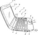
图1是作为本发明的电子设备一例的笔记本PC的、开状态的立体图。FIG. 1 is a perspective view of an open state of a notebook PC as an example of the electronic device of the present invention.
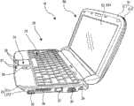
图2是示出图1所示的笔记本PC的左侧面的、开状态的立体图。FIG. 2 is a perspective view showing the left side of the notebook PC shown in FIG. 1 in an open state.
图3是示出图1所示的笔记本PC的右侧面的、开状态的立体图。FIG. 3 is a perspective view showing the right side of the notebook PC shown in FIG. 1 in an open state.
图4是在图1~图3示出开状态的笔记本PC的、闭状态的立体图。4 is a perspective view of the closed state of the notebook PC shown in the open state in FIGS. 1 to 3 .
图5是示出在图1~图4所示的笔记本PC处于闭状态时的、主体单元的底面的立体图。5 is a perspective view showing the bottom surface of the main unit when the notebook PC shown in FIGS. 1 to 4 is in a closed state.
图6是主体单元底面的分解立体图。Fig. 6 is an exploded perspective view of the bottom surface of the main body unit.
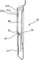
图7是示出盖住收纳了HDD的收纳部的盖的内面的图。FIG. 7 is a diagram showing the inner surface of a cover that covers a housing portion in which an HDD is housed.
图8是将朝向主体单元的底面侧的面为上来示出了HDD的立体图。8 is a perspective view showing the HDD with the surface facing the bottom surface of the main body unit facing upward.
图9是将朝向主体单元的上面侧的面为上来示出了HDD的立体图。FIG. 9 is a perspective view showing the HDD with the surface facing the upper surface of the main body unit facing upward.
图10是示出收纳在主体单元的收纳部中的、连接器结合前状态的HDD的图。FIG. 10 is a diagram showing the HDD stored in the storage portion of the main body unit before the connector is connected.
图11是示出HDD的最终收纳状态的图。FIG. 11 is a diagram showing the final storage state of the HDD.
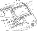
图12是示出取下了盖住收纳HDD的收纳部的盖、以及盖住存储器基板收纳部的盖这双方的状态的图。FIG. 12 is a diagram showing a state where both the cover covering the storage section for housing the HDD and the cover covering the memory substrate storage section are removed.
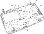
图13是示出取下了盖住收纳HDD的收纳部的盖、以及盖住存储器基板收纳部的盖这双方的状态的图。FIG. 13 is a diagram showing a state in which both the cover covering the storage section for housing the HDD and the cover covering the memory substrate storage section are removed.
图14是示出从图13所示的状态进一步拔出了存储器基板的状态的图。FIG. 14 is a diagram showing a state where the memory substrate is further pulled out from the state shown in FIG. 13 .
图15是示出遍布在主体单元壳体内的基板的图。Fig. 15 is a diagram showing a substrate spread throughout the body unit case.
图16是主体单元仰视图。Fig. 16 is a bottom view of the main body unit.
图17是沿着图16所示的箭头A-A的主体单元的剖视图。Fig. 17 is a sectional view of the main body unit along the arrow A-A shown in Fig. 16 .
图18是示出图1等所示的笔记本PC 10的主体单元上表面的一部分的放大立体图。FIG. 18 is an enlarged perspective view showing part of the upper surface of the main body unit of the notebook PC 10 shown in FIG. 1 and the like.
图19是示出构成主体单元的壳体的上罩的内面的立体图。Fig. 19 is a perspective view showing an inner surface of an upper cover constituting a casing of the main body unit.
图20是该上罩的一部分的放大立体图。Fig. 20 is an enlarged perspective view of a part of the upper cover.
图21是示出传感器基板的传感器面的图。FIG. 21 is a diagram showing a sensor surface of a sensor substrate.
具体实施方式Detailed ways
以下,举出笔记本PC的一例来对本发明的实施方式进行说明。Hereinafter, an embodiment of the present invention will be described with reference to an example of a notebook PC.
图1是作为本发明的电子设备一例的笔记本PC的、开状态的立体图。另外,图2、图3是分别示出图1所示的笔记本PC的左侧面及右侧面的、开状态的立体图。而且,图4是在图1~图3示出开状态的笔记本PC的、闭状态的立体图。FIG. 1 is a perspective view of an open state of a notebook PC as an example of the electronic device of the present invention. 2 and 3 are perspective views showing the left side and the right side of the notebook PC shown in FIG. 1 in an open state, respectively. 4 is a perspective view of the closed state of the notebook PC shown in the open state in FIGS. 1 to 3 .
该笔记本PC 10具有主体单元20和显示单元50。显示单元50与主体单元20铰链连接,在图1~图3所示的开状态与图4所示的闭状态之间进行开闭。The notebook PC 10 has a
该笔记本PC 10的主体单元20的壳体21具有上面罩211和底面罩212。在该主体单元20的上表面配置有电源按钮22、多个指示灯23、键盘24、触控板25、左右2个按压按钮26、多个指示灯27。当用手指在该触控板25上进行描绘时,后述的显示单元50的显示画面上的光标向与触控板25上的手指的移动对应的方向移动。左右2个按压按钮26相当于通用的指向设备、即鼠标的左右按压按钮。The
另外,在该主体单元20的壳体21的上面罩211的上表面12,在触控板25的右侧附近形成有凹部28。该凹部28形成为,在从上面侧俯视观察时呈圆形且越是该圆形的中央侧越向底面侧凹陷得大的曲面,例如典型地形成为构成球的一部分的曲面。当在该凹部28上放上手指而以沿着其外形描出圆形轨迹的方式用手指进行描绘时,显示在显示画面上的图像根据其描绘的方向,向上或向下滚动。Further, on the upper surface 12 of the
另外,在笔记本PC 10的主体单元20的前端面上配置有存储卡插入用卡插槽29、未图示的扬声器出声口、未图示的麦克风/耳机的插孔。In addition, on the front face of the
另外,如图2所示,在该笔记本PC 10的主体单元20的左侧面上,在底面罩212上形成有安全锁孔31及吸气口32,而且,在设置于底面罩212的各开口内配置有2个USB连接器33、微型USB连接器34。In addition, as shown in FIG. 2, on the left side of the
另外,如图3所示,在该笔记本PC 10的主体单元20的右侧面上配置有USB连接器35、设置于底面罩212的排气口36、LAN连接器37、CRT用连接器38及DC电源插孔39。In addition, as shown in FIG. 3, a
另外,显示单元50是从构成壳体51的框状的前罩511呈现LCD(液晶显示装置)52的显示画面521。该LCD 52的背面被构成壳体51的后罩512(参照图4)覆盖。另外,LCD是显示模块的一例,也可以是其他类别的PDP(等离子显示单元)等,不限定其类别。In addition, in the
另外,设置在主体单元20上的各种指示灯、各种连接器及开口的个数、种类、形状及其设置位置不限定于本实施方式,根据对于电子设备的规格要求来适当变更。In addition, the number, type, shape, and installation position of various indicator lights, various connectors, and openings provided on the
(HDD固定结构)(HDD fixed structure)
图5是示出在图1~图4所示的笔记本PC处于闭状态时的、主体单元的底面的立体图。另外,图6是主体单元底面的分解立体图。5 is a perspective view showing the bottom surface of the main unit when the notebook PC shown in FIGS. 1 to 4 is in a closed state. In addition, FIG. 6 is an exploded perspective view of the bottom surface of the main body unit.
如图6所示,在主体单元20内设置有收纳HDD 60的收纳部41,在构成该主体单元20的壳体21的底面罩212上设置有将该收纳部41向底面侧开放的开口214。在图5中示出,在主体单元20的底面出现盖住该开口214的盖213的状态,在图6中,示出该盖213与HDD 60分解的状态。As shown in FIG. 6 , a
在HDD 60上固定有沿着左右两侧面中的一侧面延伸的安装配件61。HDD 60通过该安装配件61固定在壳体21内。详细内容如后所述。A mounting
另外,在主体单元20的底面罩212上形成有存储器基板收纳部的开口,在图5、图6中还示出盖住该开口的盖215。In addition, an opening of the memory substrate storage portion is formed in the
图7是示出盖住收纳有HDD的收纳部的盖的内面的图。FIG. 7 is a diagram showing the inner surface of a cover that covers a housing portion in which an HDD is housed.
该盖体213具有:与底面罩212(参照图5、图6)一起形成主体单元20的底面的板状的主体213a;以及固定在该主体213a内面的金属板213b。该金属板213b负责主体单元20的内部电路的屏蔽。另外,该金属板213b的一部分向与基板213a的内面分开的方向弯曲,形成按压HDD 60的弹性片213c。The
图8是将朝向主体单元20的底面侧的面为上来示出了HDD的立体图。另外,图9是将朝向主体单元20的上面侧的面为上来示出了HDD的立体图。FIG. 8 is a perspective view showing the HDD with the surface facing the bottom surface side of the
在HDD 60的、朝向主体单元20上面侧的面(图9所示的面)上,遍布有该HDD60用的控制基板62。在该控制基板62上设置有圆孔621,从该圆孔621窥视到电机的底面601。该电机是使内置在该HDD 60中的圆盘状的存储媒体、即硬盘(HD)旋转的电机。如上所述,该HDD 60具有机械式的可动部,是伴随机械式的动作而访问信息的存储装置。On the surface of the
另外,如图9所示,在该HDD 60上,在其前端设置有连接器63,该连接器63用于在该HDD 60与外部之间收发数据、或者从外部接收电力的供给。In addition, as shown in FIG. 9, on the
另外,如图8所示,在该HDD 60中,在该HDD 60的第1侧面上螺纹固定有安装配件61,该安装配件61沿着该第1侧面的长度方向而向前后延伸,该第1侧面是该HDD 60的两侧面中的一侧面。在该安装配件61上,在HDD 60的前端侧的一处设置有1个固定孔611,该固定孔611用于将收纳在主体单元20的收纳部41(参照图6)中的状态的HDD 60螺纹固定在主体单元20上。HDD 60仅在该一处螺纹固定在主体单元20内。In addition, as shown in FIG. 8, in the
图10是示出收纳在主体单元的收纳部的、连接器结合前状态的HDD的图。另外,图11是示出了HDD的最终收纳状态的图。FIG. 10 is a diagram showing an HDD stored in a storage portion of a main body unit before a connector is connected. In addition, FIG. 11 is a diagram showing the final storage state of the HDD.
HDD 60以如图10所示的方式收纳在收纳部41内,之后,HDD 60的前端的连接器63向前方(主基板上的连接器71的方向)滑动,以与主基板上的连接器71组合。于是,双方的连接器63、71组合,而且安装配件61的固定孔611与形成在凸起部72中央的螺纹孔721重叠,该凸起部72设置在固定于主体单元20的壳体21的部件上。在该状态下使用这些固定孔611和螺纹孔721,使安装配件61如图11所示螺纹固定。The
图12、图13是示出取下了盖住收纳HDD的收纳部的盖、以及盖住存储器基板收纳部的盖这双方的状态的图。其中,图12示出收纳了HDD的状态,图13示出进一步取下了HDD的状态。FIGS. 12 and 13 are diagrams showing a state in which both the cover covering the storage portion for housing the HDD and the cover covering the memory substrate storage portion are removed. Among them, FIG. 12 shows the state where the HDD is accommodated, and FIG. 13 shows the state where the HDD is further removed.
如这些图12、图13所示,当取下盖住存储器基板收纳部42的开口216的盖215(参照图6、图10、图11)时,会出现收纳了存储器基板73的存储器基板收纳部42。在该存储器基板73上搭载有存储器芯片,能够根据需要替换为搭载有存储容量不同的存储器芯片的存储器基板。As shown in these FIGS. 12 and 13, when the cover 215 (see FIGS. 6, 10, and 11) that covers the
另外,如图13所示,在收纳HDD的收纳部41上配置有承受HDD的图9所示一侧的面的橡胶板411,缓和对HDD的振动传递。In addition, as shown in FIG. 13 , a
图14是示出从图13所示的状态进一步拔出了存储器基板的状态的图。而且,图15是示出了在主体单元的壳体内遍布的基板的图。该图15是将图14所示状态的主体单元壳体翻过来而将原先的上表面为上,取下主体单元壳体的上面罩及键盘而示出位于其里面的基板的图。FIG. 14 is a diagram showing a state where the memory substrate is further pulled out from the state shown in FIG. 13 . Also, FIG. 15 is a diagram showing a substrate spread throughout the housing of the main body unit. This Fig. 15 is to turn over the main unit case of the state shown in Fig. 14 and turn the original upper surface up, take off the top cover and the keyboard of the main unit case, and show the board located inside it.
图13所示的存储器基板73是以与主基板70重叠的方式配置,当取下存储器基板70时,在其里面看到主基板的一部分。如图15所示,该主基板70很广地遍布在主体单元壳体内。在该主基板70上搭载有CPU等、进行运算处理和针对显示画面521(参照图1)的图像显示控制的电路要素。在该主基板70上搭载有以从收纳HDD的收纳部41突出的方式配置的连接器71。如图10等所示,该连接器71是与HDD 60的连接器63组合的连接器。The
另外,在主基板70上搭载有2个开关79。这些各开关79是分别接受在图1等所示的2个按压按钮26的按下操作而接通的开关。通过各开关79,检测各按压按钮26的按下操作。In addition, two
图16是主体单元仰视图,图17是沿着图16所示的箭头A-A的主体单元的剖视图。Fig. 16 is a bottom view of the main body unit, and Fig. 17 is a sectional view of the main body unit along the arrow A-A shown in Fig. 16 .
在设置于主体单元20的收纳部41内收纳有HDD 60,沿着该第1侧面的安装配件61被螺纹固定主体单元20内(参照图10、图11)。The
另外,在设置于底面罩212的、装卸自如地盖住该收纳部41的开口214的盖213的内面上固定有金属板213b(参照图7),该金属板213b的一部分向内侧弯曲而形成弹性片213c。在HDD 60中,通过该弹性片213c按压第2侧面的附近,该第2侧面是该HDD 60的朝向开口214侧的面,且位于与通过安装配件61螺纹固定的第1侧面分开的一侧。由此,HDD 60的第2侧面侧,处于夹在放置于收纳部41的橡胶板411与弹性片213c之间的状态。In addition, a
如上所述,在本实施方式中,在HDD 60的第1侧面和第2侧面中只有第1侧面通过安装配件61而固定。第2侧面侧不使用安装配件,使原先设置在盖213内面的用于屏蔽的金属板213b弯曲而成为弹性片213c,通过用该弹性片213c来按压,将HDD 60稳定地保持在收纳部41内。由于安装配件61只有第1侧面侧,因此能够相应地缩小收纳部41,另外,还能够减少组装工时,而且还有助于笔记本PC 10整体的轻量化。As described above, in this embodiment, only the first side surface of the
在本实施方式中,安装配件51虽然是沿着HDD 60的第1侧面的侧面延伸的结构,但是也可以是分别安装在第1侧面的前端部及后端部并固定HDD 60的第1侧面的2个部件结构。此时,各部件只要具有分别固定在主体单元20上的结构即可。In the present embodiment, although the mounting
本实施方式的橡胶板411也可以不是如图14所示的小片,而具有沿着HDD 60的第2侧面的长度方向而向前后延伸的与第2侧面大致一致的长度。另外,橡胶板411也可以替换为覆盖收纳部41的全面的片。The
另外,在本实施方式中对于作为固定对象的电子部件虽然例示了HDD,但是也可以将SSD(Solid State Drive)等其他类别的电子部件作为对象。In addition, in the present embodiment, HDD is exemplified as an electronic component to be fixed, but other types of electronic components such as SSD (Solid State Drive) may also be targeted.
(滚动垫结构)(rolling mat structure)
图18是示出图1等所示的笔记本PC 10的主体单元上表面的一部分的放大立体图。FIG. 18 is an enlarged perspective view showing part of the upper surface of the main body unit of the
如参照图1等说明,在主体单元20的上面跟前侧设置有触控板25、左右2个按压按钮26。另外,在构成该主体单元20的壳体21的上罩211的上表面,在触控板25的右侧附近形成有凹部28,该凹部28从上面侧俯视观察时呈圆形,越靠近该圆形的中央侧越向底面侧大幅凹陷,且由球的一部分的形状构成。As described with reference to FIG. 1 and the like, a
该凹部28是作为显示在显示画面521(参照图1)中的图像的滚动用操作件来使用。The
图19是示出构成主体单元的壳体的上罩的内面的立体图。Fig. 19 is a perspective view showing an inner surface of an upper cover constituting a casing of the main body unit.
另外,图20是该上罩的一部分的放大立体图。In addition, FIG. 20 is an enlarged perspective view of a part of the upper cover.
在上罩212的内面,遍布有兼具键盘24的支撑和内部电路屏蔽功能的金属板217。另外,在该上罩212的内面固定有传感器基板80。该传感器基板80具有跨过设置有触控板25和凹部28(参照图18)的区域的宽度,遍布在触控板25和凹部28双方的背面。On the inner surface of the
另外,此处还出现了图18所示的左右2个按压按钮26的内面。在这些各按压按钮26的背面设置有突起261。当对各按压按钮26进行按下操作时,通过这些各突起261,搭载在主基板70上的各开关79(参照图15)被按下,检测到对各按压按钮26进行了按下操作。In addition, the inner surfaces of the two left and
图21是示出传感器基板的传感器面的图。FIG. 21 is a diagram showing a sensor surface of a sensor substrate.
该传感器面是传感器基板80的、与图19、图20所示的面相对的背面。在该传感器面上排列有多个静电传感器。第1区域801具有二维地排列的矩形的多个静电传感器。另外,第2区域802具有排列为圆形的多个静电传感器。This sensor surface is the back surface of the
该传感器基板80是以将图21的传感器面朝向上(上罩内面)而使区域801位于触控板25的背面、使区域802位于凹部28的背面的方式固定在上罩211的内面。当使手指与触控板25或者凹部28接触或接近时,在传感器基板80中,检测到由该接触或接近引起的静电容量的变化。The
在传感器基板80中,通过区域801的静电传感器,检测用手指在触控板25上向任意方向描绘时的、其描绘的方向。而且,在该传感器基板80中,通过区域802的静电传感器,检测用手指在凹部28中描出圆形轨迹来进行描绘时的、其描绘的方向。In the
传感器基板80通过扁平电缆81(参照图19、20)与主基板70(参照图15)连接。传感器基板80上的检测结果经由该扁平电缆80而传递到主基板70。主基板70还起到负责显示单元50的显示画面521上的图像和光标的显示控制的控制部的作用。在主基板70中,根据传感器基板80中的检测结果,控制显示画面521上的图像和光标。具体地讲,该主基板70,在触控板25被描绘时使显示画面521上的光标向与触控板25上的手指的移动对应的方向移动。另外,该主基板70,在对凹部28进行描绘而描出圆形轨迹时,使显示画面521上的图像向与描绘的圆形轨迹的方向对应的方向滚动。The
由于上述的凹部28如上所述具有如球的一部分那样平稳地凹陷的形状,因此提高如用手指描出圆形轨迹那样进行操作时的操作性。另外,成为在设计上也优秀的形状。Since the above-mentioned
在本实施方式中,虽然凹部28形成在触控板25的右侧附近,但是只要形成在触控板25的左侧附近或其他位置等不妨碍键盘操作的位置即可。In this embodiment, although the recessed
此处,虽然以笔记本PC为例进行了说明,但是本发明不限定于笔记本PC,可以在各种电子设备中广泛应用。Here, although the notebook PC is used as an example for description, the present invention is not limited to the notebook PC, and can be widely applied to various electronic devices.
符号说明Symbol Description
10笔记本PC10 Notebook PCs
20 主体单元20 main unit
21、51 壳体21, 51 shell
24 键盘24 keyboards
25 触控板25 Touchpad
26 按压按钮26 Press the button
28 凹部28 concave
36 排气口36 Exhaust port
41 收纳部41 storage department
50 显示单元50 display units
52 LCD(液晶显示装置)52 LCD (liquid crystal display device)
60 HDD60 HDDs
61 安装配件61 Mounting accessories
62 控制基板62 control board
63、71 连接器63, 71 connector
70 主基板70 main board
72 凸起部72 raised part
73 存储器基板73 Memory substrate
79 开关79 switch
80 传感器基板80 sensor substrate
81 扁平电缆81 flat cable
211 上罩211 Upper cover
212 底面罩212 bottom mask
213 盖213 cover
213a 基板213a Substrate
213b 金属板213b sheet metal
213c 弹性片213c elastic sheet
214 开口214 opening
261 突起261 protrusions
411 橡胶板411 rubber sheet
512 后罩512 rear cover
521 显示画面521 display screen
611 固定孔611 Fixing hole
721 螺纹孔721 threaded hole
Claims (7)
Translated fromChineseApplications Claiming Priority (1)
| Application Number | Priority Date | Filing Date | Title |
|---|---|---|---|
| PCT/JP2009/070316WO2011067844A1 (en) | 2009-12-03 | 2009-12-03 | Electronic device |
Publications (1)
| Publication Number | Publication Date |
|---|---|
| CN102640224Atrue CN102640224A (en) | 2012-08-15 |
Family
ID=44114709
Family Applications (1)
| Application Number | Title | Priority Date | Filing Date |
|---|---|---|---|
| CN2009801627135APendingCN102640224A (en) | 2009-12-03 | 2009-12-03 | Electronic device |
Country Status (4)
| Country | Link |
|---|---|
| US (1) | US20120243161A1 (en) |
| JP (1) | JPWO2011067844A1 (en) |
| CN (1) | CN102640224A (en) |
| WO (1) | WO2011067844A1 (en) |
Families Citing this family (3)
| Publication number | Priority date | Publication date | Assignee | Title |
|---|---|---|---|---|
| USD710841S1 (en)* | 2012-10-23 | 2014-08-12 | Apple Inc. | Electronic device |
| US10691176B2 (en)* | 2018-07-12 | 2020-06-23 | Google Llc | Textured pattern surface for a computing device |
| TWI704396B (en)* | 2019-08-15 | 2020-09-11 | 啟碁科技股份有限公司 | Electronic display device |
Family Cites Families (12)
| Publication number | Priority date | Publication date | Assignee | Title |
|---|---|---|---|---|
| JPH03171313A (en)* | 1989-11-30 | 1991-07-24 | Toshiba Corp | Compact electronic equipment |
| JP4105309B2 (en)* | 1997-11-06 | 2008-06-25 | 富士通株式会社 | Electronic device and mounting mechanism |
| KR100840941B1 (en)* | 2002-12-11 | 2008-06-24 | 삼성전자주식회사 | Portable computer |
| JP2005157790A (en)* | 2003-11-26 | 2005-06-16 | Toshiba Corp | Electronics |
| JP2006040966A (en)* | 2004-07-22 | 2006-02-09 | Fujitsu Ltd | Electronic equipment |
| JP4909510B2 (en)* | 2004-12-20 | 2012-04-04 | 株式会社東芝 | Electronics |
| JP2007328531A (en)* | 2006-06-07 | 2007-12-20 | Toshiba Corp | Electronic appliance |
| JP2007095079A (en)* | 2006-10-02 | 2007-04-12 | Fujitsu Ltd | Shock absorber for built-in unit for electronic devices and electronic devices |
| JP4909774B2 (en)* | 2007-03-19 | 2012-04-04 | 株式会社東芝 | Electronic devices and personal computers |
| JP4815385B2 (en)* | 2007-04-13 | 2011-11-16 | 株式会社日立製作所 | Storage device |
| JP2009043096A (en)* | 2007-08-09 | 2009-02-26 | Fujitsu Ltd | Electronics |
| JP4952434B2 (en)* | 2007-08-09 | 2012-06-13 | 富士通株式会社 | Electronic component mounting parts and electronic equipment |
- 2009
- 2009-12-03WOPCT/JP2009/070316patent/WO2011067844A1/ennot_activeCeased
- 2009-12-03JPJP2011544151Apatent/JPWO2011067844A1/enactivePending
- 2009-12-03CNCN2009801627135Apatent/CN102640224A/enactivePending
- 2012
- 2012-06-01USUS13/486,465patent/US20120243161A1/ennot_activeAbandoned
Also Published As
| Publication number | Publication date |
|---|---|
| JPWO2011067844A1 (en) | 2013-04-18 |
| WO2011067844A1 (en) | 2011-06-09 |
| US20120243161A1 (en) | 2012-09-27 |
Similar Documents
| Publication | Publication Date | Title |
|---|---|---|
| TWI512432B (en) | Electronic device | |
| EP0947910A2 (en) | A palm-sized computer assembly | |
| JP4768479B2 (en) | Electronics | |
| JP5724535B2 (en) | Electronic equipment | |
| CN100579343C (en) | Information processing device and manufacturing method thereof | |
| CN108345357A (en) | Display device and electronic equipment | |
| US20140111926A1 (en) | Printed circuit board features of a portable computer | |
| CN100412752C (en) | electronic device | |
| CN103716424A (en) | Electronic device and assembling method thereof | |
| CN103376836A (en) | Electronic device | |
| JP4991122B2 (en) | Electronics | |
| JP4819538B2 (en) | Electronics | |
| JP4282671B2 (en) | Electronics | |
| JP4799017B2 (en) | Electronics | |
| CN102640224A (en) | Electronic device | |
| US9158385B2 (en) | Input receiver and electronic device | |
| JP4686221B2 (en) | Electronics | |
| WO2014092798A1 (en) | Keyboard configuration for an electronic device | |
| CN103853259B (en) | Electronic device | |
| JP2012004031A (en) | Electronic device | |
| WO2011067845A1 (en) | Electronic device | |
| JP2816318B2 (en) | Electronics | |
| JP5117598B2 (en) | Electronics | |
| US20240103641A1 (en) | Keyboard housings with flexible touch sensing components | |
| JP2007048085A (en) | Electronics |
Legal Events
| Date | Code | Title | Description |
|---|---|---|---|
| C06 | Publication | ||
| PB01 | Publication | ||
| C10 | Entry into substantive examination | ||
| SE01 | Entry into force of request for substantive examination | ||
| C02 | Deemed withdrawal of patent application after publication (patent law 2001) | ||
| WD01 | Invention patent application deemed withdrawn after publication | Application publication date:20120815 |