CN102637973A - Rectangular connector - Google Patents
Rectangular connectorDownload PDFInfo
- Publication number
- CN102637973A CN102637973ACN201210079853XACN201210079853ACN102637973ACN 102637973 ACN102637973 ACN 102637973ACN 201210079853X ACN201210079853X ACN 201210079853XACN 201210079853 ACN201210079853 ACN 201210079853ACN 102637973 ACN102637973 ACN 102637973A
- Authority
- CN
- China
- Prior art keywords
- insulator
- reed
- installation
- limit
- bottom plate
- Prior art date
- Legal status (The legal status is an assumption and is not a legal conclusion. Google has not performed a legal analysis and makes no representation as to the accuracy of the status listed.)
- Granted
Links
Images


Landscapes
- Connector Housings Or Holding Contact Members (AREA)
Abstract
Translated fromChinese
Description
Translated fromChinese技术领域technical field
本发明涉及电连接器技术领域,尤其涉及一种矩形连接器。The invention relates to the technical field of electrical connectors, in particular to a rectangular connector.
背景技术Background technique
现有的矩形连接器一般可以分为非金属壳体矩形连接器和金属壳体矩形连接器。金属壳体矩形连接器的结构包括连接器壳体和用于安装接触件的绝缘体部件,绝缘体部件通过绝缘体安装簧片安装在连接器壳体中。Existing rectangular connectors can generally be classified into non-metallic housing rectangular connectors and metal housing rectangular connectors. The structure of the metal shell rectangular connector includes a connector shell and an insulator part for mounting contacts, and the insulator part is installed in the connector shell through an insulator mounting reed.
绝缘体安装簧片一般有两种,一种为压板式定位结构,即绝缘体部件通过压板和标准件(如螺钉、垫片)等固定在连接器壳体内,从而保证连接器内接触件的可靠接触,这种压板式结构从设计上来说,就已经决定了绝缘体部件和连接器壳体必须在连接器制造厂商的厂房内一次性组装成功,然后才能交付用户使用,在用户使用时再将接触件装入连接器中使用,这种传统结构中可取卸部件都是单个接触件取卸,当接触件芯数很多时,在空间狭小的现场安装使用将为变的非常困难。而且如果是带压板不可更换模块式的连接器维修时必须将整个连接器拆下重新换装,非常费时费力。如果是带压板可更换模块式的连接器维修时也需要将压板去掉,在更换有问题的模块后重新装回压板才可完成维修,压板的拆装也大大增加了维修人员的劳动强度,降低了维修人员的工作效率。There are generally two types of insulator mounting reeds, one is the pressure plate positioning structure, that is, the insulator parts are fixed in the connector housing through the pressure plate and standard parts (such as screws, gaskets), so as to ensure reliable contact of the contacts in the connector , the design of this pressure plate structure has determined that the insulator parts and the connector housing must be assembled successfully in the factory of the connector manufacturer at one time, and then they can be delivered to the user. It is used in a connector. In this traditional structure, the detachable parts are a single contact piece. When there are many contacts, it will be very difficult to install and use in a small space. Moreover, if it is a non-replaceable modular connector with a pressure plate, the entire connector must be removed and replaced during maintenance, which is very time-consuming and laborious. If it is a replaceable modular connector with a pressure plate, it is also necessary to remove the pressure plate during maintenance. The maintenance can only be completed by reinstalling the pressure plate after replacing the problematic module. The disassembly and assembly of the pressure plate also greatly increases the labor intensity of the maintenance personnel and reduces Improve the efficiency of maintenance personnel.
另一种为免压板式定位结构,即在连接器壳体上开定位槽,然后再绝缘体部件上设计有倒刺结构,可以保证绝缘体部件在安装后由于倒刺的存在而不会从连接器壳体中脱出,实现固定绝缘体部件的目的,由于高分子工程塑料自身的特性使得此种倒刺结构具有一定的弹性,利用取卸工具将倒刺顶开即可实现绝缘体部件从壳体中安全取出而不会破坏任何零部件。但是由于高分子工程材料既要满足高强度高绝缘性,还要满足有弹性的要求,设置于绝缘体部件上的倒刺结构必然不会很大,倒刺结构使用寿命有限,在取卸一定次数后,存在绝缘体部件固定不牢靠的风险,这时就需要更换新的绝缘体部件,造成成本的浪费。The other is a pressure-free plate positioning structure, that is, a positioning groove is opened on the connector housing, and then a barb structure is designed on the insulator part, which can ensure that the insulator part will not fall out of the connector due to the barb after installation. The purpose of fixing the insulator parts is achieved by protruding from the shell. Due to the characteristics of polymer engineering plastics, the barb structure has a certain degree of elasticity. Remove without damaging any parts. However, since polymer engineering materials must not only meet the requirements of high strength and high insulation, but also meet the requirements of elasticity, the barb structure set on the insulator part must not be very large, and the service life of the barb structure is limited. Finally, there is a risk that the insulator part is not securely fixed, and at this time it is necessary to replace a new insulator part, resulting in waste of cost.
发明内容Contents of the invention
本发明的目的在于提供一种矩形连接器,以解决现有矩形连接器中的绝缘体安装结构拆装不便和使用寿命短暂的问题。The purpose of the present invention is to provide a rectangular connector to solve the problems of inconvenient assembly and disassembly and short service life of the insulator mounting structure in the existing rectangular connector.
为了解决上述问题,本发明中的技术方案为:In order to solve the above problems, the technical solution in the present invention is:
一种矩形连接器,包括前端为插接端的连接器壳体和用于安装相应接触件的绝缘体部件,所述的连接器壳体内设有具有四个拐角部的矩形内腔,所述的绝缘体部件通过绝缘体安装簧片安装在所述的矩形内腔中,所述的绝缘体安装簧片包括底板及与所述底板的左右侧边通过弯折结构一体连接的两侧壁板,所述的底板和两侧壁板构成U形槽结构,所述的底板上设有前端与所述底板一体设置、末端朝前延伸并向所述U形槽结构的槽口方向翻折的前定位簧片,所述的底板还设有前端与所述底板一体设置、末端朝后延伸且翻折方向与所述前定位簧片翻折方向相反的后定位簧片,所述绝缘体安装簧片的前端设有限位面朝向前方的限位棱边,所述矩形内腔的对应两个拐角部设有供所述绝缘体安装簧片的弯折结构由前至后滑动装入的导向滑道,所述矩形内腔的腔壁上设有与所述绝缘体安装簧片的的限位棱边挡止配合以使所述绝缘体安装簧片向前移动限位的安装结构限位台阶和与所述绝缘体安装簧片的后定位簧片定位配合以使所述绝缘体安装簧片向后移动限位的安装结构定位沟槽,所述的绝缘体部件上设有与所述前定位簧片定位配合以使所述绝缘体部件向后移动限位的绝缘体安装簧片限位槽。A rectangular connector, including a connector housing with a plug-in end at the front end and an insulator part for installing corresponding contacts. The connector housing is provided with a rectangular inner cavity with four corners. The insulator Components are installed in the rectangular inner cavity through an insulator installation reed. The insulator installation reed includes a bottom plate and two side wall plates integrally connected with the left and right sides of the bottom plate through a bending structure. The bottom plate It forms a U-shaped groove structure with the two side wall plates, and the bottom plate is provided with a front positioning reed whose front end is integrally arranged with the bottom plate, the end extends forward and is folded toward the notch of the U-shaped groove structure, The base plate is also provided with a rear positioning reed whose front end is integrated with the base plate, whose end extends backward and whose folding direction is opposite to that of the front positioning reed. The bit surface is facing the front limiting edge, and the corresponding two corners of the rectangular inner cavity are provided with guide slides for the bending structure of the insulator mounting reed to be slid from front to back. The wall of the cavity is provided with a limit edge of the insulator installation reed to stop and cooperate with the installation structure limit step of the insulator installation reed to move forward and limit the position with the insulator installation reed. The rear positioning reed is positioned and matched so that the insulator mounting reed moves backward to limit the installation structure positioning groove, and the insulator part is provided with the front positioning reed to position and cooperate to make the insulator part The insulator that moves backward is installed the reed limit slot.
所述的后定位簧片设置于所述前定位簧片后方的底板上。The rear positioning reed is arranged on the bottom plate behind the front positioning reed.
所述底板两侧绝缘体安装簧片上一体设有向后凸起的且具有相对方向限位面的凸起限位筋板,所述矩形内腔的腔壁上一体内翻有与所述两个凸起限位筋板挡止配合以阻止所述绝缘体安装簧片在矩形内腔中周向移动的内翻沿。The mounting springs of the insulators on both sides of the bottom plate are integrally provided with protruding limiting ribs that protrude backward and have a limiting surface in the opposite direction. The protruding limiting rib blocks the inversion edge which cooperates to prevent the insulator installation reed from moving circumferentially in the rectangular inner cavity.
在垂直于前后方向的截面上,所述弯折结构的截面形状为圆弧形,所述圆弧形的弯折结构由与底板相连的内凹段和与对应壁板相连的外凸段构成,所述矩形内腔的导向滑道的形状为与所述绝缘体安装簧片的弯折结构吻配的弧形导向滑道。On a section perpendicular to the front-to-back direction, the cross-sectional shape of the bent structure is arc-shaped, and the arc-shaped bent structure is composed of an inner concave section connected with the bottom plate and an outer convex section connected with the corresponding wall plate , the shape of the guide slideway in the rectangular inner cavity is an arc-shaped guide slideway matched with the bending structure of the installation reed of the insulator.
所述矩形内腔的腔壁上还设有绝缘体限位台阶,所述绝缘体部件的外周一体设有与所述绝缘体限位台阶挡止配合以使绝缘体部件向前移动限位的绝缘体配合部。The cavity wall of the rectangular inner cavity is also provided with an insulator limiting step, and the outer circumference of the insulator part is integrally provided with an insulator matching part which is engaged with the insulator limiting step so that the insulator part moves forward to limit the position.
所述的限位棱边由所述绝缘体安装簧片的两侧壁板的前端部棱边构成,所述的安装结构限位台阶设置于对应导向滑道的前端。The limiting edge is formed by the edge of the front end of the two side wall panels of the insulator mounting reed, and the limiting step of the installation structure is arranged at the front end of the corresponding guide slide.
本发明的有益效果为:绝缘体安装簧片利用其两侧的弯折结构滑动装入连接器壳体的矩形内腔中,在绝缘体安装簧片的后定位簧片滑入安装结构定位沟槽时,在安装结构限位台阶、安装结构定位槽沟和弧形导向滑道的共同定位下,绝缘体安装簧片与连接器壳体保持相对固定;然后将绝缘体部件装入矩形内腔中,从而保证绝缘体部件的安装可靠。由于绝缘体部件通过簧片和台阶定位,非常方便拆装,同时绝缘体安装簧片与绝缘体部件的分开设置,使前定位簧片的结构不再受限制,U形绝缘体安装簧片的使用寿命得到保证,也避免了成本的浪费。The beneficial effects of the present invention are: the insulator mounting reed slides into the rectangular inner cavity of the connector housing by using the bending structure on both sides, when the rear positioning reed of the insulator mounting reed slides into the positioning groove of the mounting structure , under the common positioning of the installation structure limit step, the installation structure positioning groove and the arc-shaped guide slide, the insulator installation reed and the connector housing remain relatively fixed; then the insulator parts are put into the rectangular inner cavity to ensure The installation of the insulator parts is reliable. Since the insulator part is positioned by the reed and the steps, it is very convenient to disassemble and assemble. At the same time, the separate installation of the insulator installation reed and the insulator part makes the structure of the front positioning reed no longer restricted, and the service life of the U-shaped insulator installation reed is guaranteed. , but also to avoid the waste of cost.
附图说明Description of drawings
图1是本发明实施例的结构示意图;Fig. 1 is the structural representation of the embodiment of the present invention;
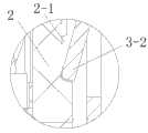
图2是图1中的A处放大图;Figure 2 is an enlarged view of A in Figure 1;
图3是图1中的B处放大图;Fig. 3 is an enlarged view of B in Fig. 1;
图4是图1中绝缘体部件的结构示意图;Fig. 4 is a schematic structural view of the insulator part in Fig. 1;
图5是图4的侧视图;Fig. 5 is a side view of Fig. 4;
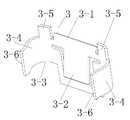
图6是图1中绝缘体安装簧片的结构示意图;Fig. 6 is a structural schematic view of the insulator mounting reed in Fig. 1;
图7是图6的俯视图;Figure 7 is a top view of Figure 6;
图8是图7的A-A向视图;Fig. 8 is the A-A direction view of Fig. 7;
图9是图6的立体图;Figure 9 is a perspective view of Figure 6;
图10是图1中连接器壳体的安装结构限位台阶的结构示意图;Fig. 10 is a structural schematic diagram of a limit step of the installation structure of the connector housing in Fig. 1;
图11是连接器壳体与绝缘体安装簧片的配合示意图。Fig. 11 is a schematic diagram of the cooperation between the connector housing and the installation reed of the insulator.
具体实施方式Detailed ways
一种矩形连接器的实施例如图1~11所示:包括前端为插接端的连接器壳体1和用于安装相应接触件的绝缘体部件2,连接器壳体1内设有具有四个拐角部的矩形内腔,绝缘体部件2通过绝缘体安装簧片3安装在矩形内腔中。绝缘体安装簧片3为铍铜簧片一体冲压件,铍铜簧片冷加工性能较好,在经热处理后强度高弹性好。绝缘体安装簧片3包括底板及与所述底板的左右侧边通过弯折结构3-4一体连接的两侧壁板,在垂直于前后方向截面上,弯折结构3-4的截面形状为圆弧形,圆弧形的弯折结构3-4有包括两部分组成,分别为与底板相连的内凹段3-4-1和与壁板相连的外凸段3-4-2。底板和两侧壁板构成U形槽结构,底板上设有前端与底板一体设置、末端朝前延伸并向所述U形槽结构的槽口方向翻折的前定位簧片3-2,底板上于前定位簧片3-2的后侧还设有前端与底板一体设置、末端朝后延伸且翻折方向与前定位簧片3-2相反的后定位簧片3-1,绝缘体安装簧片3的两侧壁板的前端部构成限位面朝向前方的限位棱边3-3,底板两侧的弯折结构3-4上分别向后一体设有具有相对方向限位面的凸起限位筋板3-5。矩形内腔的对应两个拐角部设有供绝缘体安装簧片3的弯折结构3-4由前至后滑动装入的导向滑道1-4,导向滑道1-4的形状为与对应弯折结构3-4导向吻配的圆弧导向滑道,导向滑道1-4与弯折结构3-4的内外段3-4-1和外凸段3-4-2吻合导向,保证了绝缘体安装簧片3的插装效果,导向滑道1-4也阻止了绝缘体安装簧片3-1在矩形内腔中轴向扭转和朝内外方向移动。矩形内腔的腔壁上设有与绝缘体安装簧片3的限位棱边3-3挡止配合以使绝缘体安装簧片3向前移动限位的安装结构限位台阶1-3和与绝缘体安装簧片3的后定位簧片3-1定位配合以使绝缘体安装簧片3向后移动限位的安装结构定位沟槽1-1,安装结构定位沟槽1-1的后侧槽沿处一体设有朝内凸起的并具有朝前方向限位面的凸起限位块1-2,在凸起限位块1-2后侧的连接器壳体1上还一体内翻有分别与两个凸起限位筋板3-5挡止配合以阻止绝缘体安装簧片3在矩形内腔中扭转的内翻沿1-5。绝缘体部件2上设有与前定位簧片3-2定位配合以使绝缘体部件2向后移动限位的绝缘体安装簧片限位槽2-1,安装结构限位槽2-1前方的绝缘体部件2上向外凸起设有用于使前定位簧片3-2顺利滑入安装结构限位槽2-1中的斜坡状结构2-2,绝缘体部件2的外周一体设有与相应连接器壳体1上的绝缘体限位台阶挡止配合以使绝缘体部件2向前移动限位的绝缘体配合部,绝缘体限位台阶设置于矩形内腔的墙壁上。矩形内腔的腔壁上还设有与绝缘体安装簧片3的各壁板的槽口沿3-6挡止配合以使述绝缘体安装簧片3沿矩形内腔周向移动限位的周向限位台阶1-6。图中件4表示设于连接器壳体1上的用于与相应插头连接器壳体的导向销导向定位配合的导向套。An embodiment of a rectangular connector is shown in Figures 1 to 11: it includes a
安装时,手握住绝缘体安装簧片3两侧的弯折结构3-4,将绝缘体安装簧片3推入矩形内腔的弧形导向滑道1-4中,然后将绝缘体安装簧片3推入连接器壳体1,直到听到后定位簧片3-1卡入安装结构定位沟槽1-1的轻响为止,此时绝缘体安装簧片3的两侧壁板的前端的限位棱边3-3也与安装结构限位台阶1-3挡止配合,绝缘体安装簧片3安装完成;然后进行绝缘体部件2的安装,将绝缘体部件2轻轻推入连接器壳体1中,当听到前定位簧片3-2卡入安装结构限位槽2-1的声音时,此时绝缘体部件2的绝缘体配合部也与连接器壳体1的绝缘体限位台阶挡止配合而使绝缘体部件2向前移动限位。在两个连接器对插时,前定位簧片3-2与绝缘体部件2上的安装结构限位槽2-1限位配合,安装结构定位沟槽1-1和凸起限位块1-2与后定位簧片3-1配合为连接器的对插提供支撑,对插力经后定位簧片3-1传递到连接器壳体1,防止U形绝缘体安装簧片3从连接器壳体1中脱出或松动;在两个连接器需要分开时,绝缘体限位台阶阻止绝缘体部件2前移松动。弯折结构3-4的作用有二,一是便于夹持安装,另一个就是为绝缘体安装簧片3定位;凸起限位块1-2也为后定位簧片3-1提供支撑,既有安装结构定位沟槽1-1又有凸起限位块1-2,两者配合为绝缘体安装簧片提供了可靠的固定方式。通过前、后定位簧片的使用只需轻轻的推动便可完成绝缘体部件2的安装,在需要拆卸时,使用一个简单结构的取卸器就可以轻松将绝缘体部件2从连接器壳体1中取出。When installing, hold the bending structure 3-4 on both sides of the
本实施例中的连接器为插座连接器,在本发明的其它实施例中,连接器还可以为插头连接器;凸起限位筋板还可以被与底板一体连接的其它定位结构代替;当然当弯折结构足以阻止绝缘体安装簧片在矩形内腔中扭转时,凸起限位筋板和连接器壳体上内翻沿均可以不设;弯折结构的外凸段也可以没有;连接器壳体上的限位台阶既可以与连接器壳体一体设置,也可以通过可拆方式与连接器壳体的前端相连;连接器壳体上的绝缘体限位台阶还可以不设,此时可以绝缘体部件可以通过与绝缘体安装簧片的限位配合来阻止绝缘体部件继续前移,比如将凸起限位筋板的后端棱边作为限位棱边,在绝缘体部件上设计与凸起限位筋板的后端棱边挡止配合的配合结构;当然绝缘体安装簧片的底板还可以与矩形内腔的长边所在腔壁连接;后定位簧片的设置位置还可以为前定位簧片的前侧。The connector in this embodiment is a socket connector, and in other embodiments of the present invention, the connector can also be a plug connector; the raised limiting rib can also be replaced by other positioning structures integrally connected with the bottom plate; of course When the bending structure is sufficient to prevent the insulator mounting reed from twisting in the rectangular inner cavity, the protruding limiting rib and the upper inversion edge of the connector housing can be omitted; the outer convex section of the bending structure can also be absent; the connection The limiting step on the connector housing can be set integrally with the connector housing, or can be connected to the front end of the connector housing in a detachable manner; the insulator limiting step on the connector housing can also be omitted. It is possible that the insulator part can prevent the insulator part from moving forward by the limit cooperation with the insulator installation reed, such as using the rear end edge of the raised limit rib as the limit edge, and the design on the insulator part is in line with the raised limit edge. The rear end edge of the rib plate stops and cooperates; of course, the bottom plate on which the insulator installs the reed can also be connected with the cavity wall where the long side of the rectangular inner cavity is located; the setting position of the rear positioning reed can also be the front positioning reed the front side.
Claims (6)
Translated fromChinesePriority Applications (1)
| Application Number | Priority Date | Filing Date | Title |
|---|---|---|---|
| CN201210079853.XACN102637973B (en) | 2012-03-23 | 2012-03-23 | Rectangular connector |
Applications Claiming Priority (1)
| Application Number | Priority Date | Filing Date | Title |
|---|---|---|---|
| CN201210079853.XACN102637973B (en) | 2012-03-23 | 2012-03-23 | Rectangular connector |
Publications (2)
| Publication Number | Publication Date |
|---|---|
| CN102637973Atrue CN102637973A (en) | 2012-08-15 |
| CN102637973B CN102637973B (en) | 2014-03-12 |
Family
ID=46622274
Family Applications (1)
| Application Number | Title | Priority Date | Filing Date |
|---|---|---|---|
| CN201210079853.XAExpired - Fee RelatedCN102637973B (en) | 2012-03-23 | 2012-03-23 | Rectangular connector |
Country Status (1)
| Country | Link |
|---|---|
| CN (1) | CN102637973B (en) |
Citations (3)
| Publication number | Priority date | Publication date | Assignee | Title |
|---|---|---|---|---|
| CN201562835U (en)* | 2008-09-09 | 2010-08-25 | 莫列斯公司 | Shielding cover and connector component thereof |
| JP4588206B2 (en)* | 2000-12-18 | 2010-11-24 | 日置電機株式会社 | Connection structure between electrical equipment and connection cord |
| CN202564634U (en)* | 2012-03-23 | 2012-11-28 | 中航光电科技股份有限公司 | Rectangular connector |
- 2012
- 2012-03-23CNCN201210079853.XApatent/CN102637973B/ennot_activeExpired - Fee Related
Patent Citations (3)
| Publication number | Priority date | Publication date | Assignee | Title |
|---|---|---|---|---|
| JP4588206B2 (en)* | 2000-12-18 | 2010-11-24 | 日置電機株式会社 | Connection structure between electrical equipment and connection cord |
| CN201562835U (en)* | 2008-09-09 | 2010-08-25 | 莫列斯公司 | Shielding cover and connector component thereof |
| CN202564634U (en)* | 2012-03-23 | 2012-11-28 | 中航光电科技股份有限公司 | Rectangular connector |
Also Published As
| Publication number | Publication date |
|---|---|
| CN102637973B (en) | 2014-03-12 |
Similar Documents
| Publication | Publication Date | Title |
|---|---|---|
| US6932493B2 (en) | Fluorescent light tube adaptor | |
| CN102637972A (en) | Insulator mounting reed | |
| CN204427716U (en) | A kind of food processor | |
| CN206211089U (en) | A kind of socket | |
| CN204348967U (en) | With the supply socket of USB charger | |
| CN102637973B (en) | Rectangular connector | |
| CN221923224U (en) | A light-transmitting plate strip fixed LED panel light | |
| CN102637974B (en) | Rectangular connector component | |
| CN202564634U (en) | Rectangular connector | |
| CN202633607U (en) | Rectangular connector assembly | |
| CN100552284C (en) | Pluggable fluorescent lamps and their sockets | |
| CN207250902U (en) | Motor carbon brush holder | |
| CN210800901U (en) | Line lamp with power line capable of being plugged in and pulled out for cabinet and wardrobe | |
| CN202601925U (en) | Insulator installation reed | |
| CN205208477U (en) | Female end of short money metal and LED lamp of using thereof | |
| CN204858173U (en) | Wall Plug Switching Power Supplies for Linear Actuators | |
| CN202076524U (en) | Electric connector and insulating casing | |
| CN207907154U (en) | Arrangements of electric connection, illuminator and its light fixture and mounting base | |
| CN216214227U (en) | Socket assembly for five-hole smart socket and five-hole smart socket having the same | |
| CN104300259A (en) | Reed jack and contact element assembly using same | |
| CN104565932A (en) | Integrated lamp tube | |
| CN222378029U (en) | Lamp plug connector | |
| CN222440883U (en) | Lighting | |
| CN219916335U (en) | Display apparatus | |
| CN223156393U (en) | Connector convenient to plug |
Legal Events
| Date | Code | Title | Description |
|---|---|---|---|
| C06 | Publication | ||
| PB01 | Publication | ||
| C10 | Entry into substantive examination | ||
| SE01 | Entry into force of request for substantive examination | ||
| GR01 | Patent grant | ||
| GR01 | Patent grant | ||
| CF01 | Termination of patent right due to non-payment of annual fee | ||
| CF01 | Termination of patent right due to non-payment of annual fee | Granted publication date:20140312 Termination date:20190323 |