CN102630154A - Sterile adapter, connection structure of rotating wheel and connection structure of surgical instruments - Google Patents
Sterile adapter, connection structure of rotating wheel and connection structure of surgical instrumentsDownload PDFInfo
- Publication number
- CN102630154A CN102630154ACN201080050214XACN201080050214ACN102630154ACN 102630154 ACN102630154 ACN 102630154ACN 201080050214X ACN201080050214X ACN 201080050214XACN 201080050214 ACN201080050214 ACN 201080050214ACN 102630154 ACN102630154 ACN 102630154A
- Authority
- CN
- China
- Prior art keywords
- driving wheel
- runner
- sterile adapter
- wheel
- surgical instrument
- Prior art date
- Legal status (The legal status is an assumption and is not a legal conclusion. Google has not performed a legal analysis and makes no representation as to the accuracy of the status listed.)
- Granted
Links
Images


Classifications
- B—PERFORMING OPERATIONS; TRANSPORTING
- B25—HAND TOOLS; PORTABLE POWER-DRIVEN TOOLS; MANIPULATORS
- B25J—MANIPULATORS; CHAMBERS PROVIDED WITH MANIPULATION DEVICES
- B25J17/00—Joints
- B—PERFORMING OPERATIONS; TRANSPORTING
- B25—HAND TOOLS; PORTABLE POWER-DRIVEN TOOLS; MANIPULATORS
- B25J—MANIPULATORS; CHAMBERS PROVIDED WITH MANIPULATION DEVICES
- B25J15/00—Gripping heads and other end effectors
- B25J15/04—Gripping heads and other end effectors with provision for the remote detachment or exchange of the head or parts thereof
- B25J15/0408—Connections means
Landscapes
- Engineering & Computer Science (AREA)
- Robotics (AREA)
- Mechanical Engineering (AREA)
- Surgical Instruments (AREA)
- Manipulator (AREA)
Abstract
Description
Translated fromChinese技术领域technical field
本发明涉及无菌适配器、转轮联接结构以及手术用器械的联接结构。The invention relates to a sterile adapter, a connection structure of a rotating wheel and a connection structure of surgical instruments.
背景技术Background technique
医学上的手术是指使用医疗器械对皮肤、粘膜或其它组织进行切开、切割或进行操作而治愈病的行为。特别是,切开手术部位皮肤而对其内部器官等进行治疗、整形或切除的剖腹手术等,由于出血、副作用、患者痛苦、疤痕等问题,最近使用机器人(robot)的手术备受欢迎。Medical surgery refers to the act of using medical instruments to incise, cut or manipulate skin, mucous membranes or other tissues to cure diseases. In particular, laparotomy, in which the skin of the surgical site is incised to treat, reshape, or remove internal organs, etc., surgery using robots has become popular recently due to problems such as bleeding, side effects, patient pain, and scars.
用于机器人手术中的手术机器人,由主机器人(master)部和从机器人(slave)部构成,该主机器人部根据医生的操作生成信号并传递,该从机器人接收来自主机器人的信号并对患者进行手术所需的操作,主机器人部和从机器人部可以以一个综合的机器人形式实现,或者分别以独立装置构成而配置在手术室内。The surgical robot used in robotic surgery is composed of a master robot (master) part that generates and transmits signals according to the doctor's operation, and a slave robot (slave) part that receives signals from the master robot and sends them to the patient. Operations required for surgery, the master robot unit and the slave robot unit can be implemented as a single integrated robot, or they can be configured as independent devices and placed in the operating room.
手术机器人具有用于执行手术的各种动作的机器臂,在机器臂的前端部形成有用于安装手术用器械(instrument)的器械支架。为了在机器臂上安装手术用器械,通过在器械支架结合无菌适配器(sterile adapter),并将手术用器械的外壳嵌入在无菌适配器上,从而将手术用器械安装在机器臂上。The surgical robot has a robot arm for performing various operations of surgery, and an instrument holder for mounting a surgical instrument is formed on the front end of the robot arm. In order to mount the surgical instrument on the robotic arm, the surgical instrument is mounted on the robotic arm by combining a sterile adapter with the instrument holder and embedding the shell of the surgical instrument on the sterile adapter.
在器械支架上形成有用于将机器人生成的驱动力传递给手术用器械的驱动轮,而在手术用器械上也形成有用于接收驱动力的驱动轮,在无菌适配器上形成有分别与在器械支架上形成的驱动轮及在手术用器械上形成的驱动轮匹配的转轮。A driving wheel for transmitting the driving force generated by the robot to the surgical instrument is formed on the instrument bracket, and a driving wheel for receiving the driving force is also formed on the surgical instrument. The driving wheel formed on the bracket and the rotating wheel matched with the driving wheel formed on the surgical instrument.
这些转轮结构彼此匹配地在器械支架上安装无菌适配器,而在无菌适配器上安装手术用器械,则机器人生成的驱动力通过无菌适配器传递给手术用器械,而与手术用器械的驱动轮连接的钢丝将驱动力传递给与手术用器械的末端部结合的执行器(Effector),从而执行器运行,以实现手术的各种操作。These rotating wheel structures are matched with each other to install sterile adapters on the instrument brackets, and surgical instruments are installed on the sterile adapters, then the driving force generated by the robot is transmitted to the surgical instruments through the sterile adapters, and the driving force of the surgical instruments The steel wire connected to the wheel transmits the driving force to the effector combined with the end of the surgical instrument, so that the effector operates to realize various operations of the surgery.
这样的,在手术机器人与其上安装的手术用器械之间介入有无菌适配器,在无菌适配器上实现了机器臂及手术用器械的连接(coupling)结构。In this way, a sterile adapter is interposed between the surgical robot and the surgical instruments installed thereon, and the coupling structure of the robot arm and the surgical instruments is realized on the sterile adapter.
但是,形成在现有的无菌适配器上的转轮结构是无任何弹性的结构,因此存在如下局限性,为了将无菌适配器安装在机器臂上,需要在器械支架上形成的驱动轮上使用弹簧加压式弹性结构。However, the wheel structure formed on the existing aseptic adapter is a structure without any elasticity, so there is the following limitation. In order to install the aseptic adapter on the robot arm, it is necessary to use it on the drive wheel formed on the instrument holder. Spring loaded elastic construction.
此外,在现有的机器臂、无菌适配器及手术用器械上形成的转轮结构,为了精确对齐转轮而用于检测其是否对齐的结构不完整,而且用于通过各种方法检测是否对齐及对齐之后传递运作所需力的结构也有局限性。In addition, the structure of the wheels formed on the existing robotic arms, sterile adapters, and surgical instruments has incomplete structures for detecting the alignment of the wheels in order to accurately align the wheels, and is used to detect alignment by various methods There are also limitations to the structure that transmits the forces required for operation after alignment.
上述的背景技术是发明人为了导出本发明而所持有或在导出本发明的过程中学到的技术信息,不一定是本发明申请之前被一般公众公开的公知技术。The above-mentioned background technology is the technical information held by the inventor in order to derive the present invention or learned during the process of deriving the present invention, and not necessarily the known technology disclosed to the general public before the application of the present invention.
发明内容Contents of the invention
技术问题technical problem
本发明提供一种能够在机器臂上容易安装手术用器械的无菌适配器。The present invention provides a sterile adapter capable of easily installing surgical instruments on a robot arm.
本发明目的在于提供一种利用电、磁、机械特性检测转轮是否对齐,并用于精确对齐的转轮联接结构及利用该联接结构检测医疗设备是否结合的医疗设备的联接结构。The object of the present invention is to provide a coupling structure of a rotary wheel that utilizes electric, magnetic and mechanical characteristics to detect whether the rotary wheel is aligned and is used for precise alignment, and a coupling structure of a medical device that uses the coupling structure to detect whether the medical device is combined.
除了本发明提出的问题之外的技术问题可以通过下面的说明易于理解。Technical problems other than those posed by the present invention can be easily understood through the following description.
问题解决方法problem solving
根据本发明的一实施方式,提供一种无菌适配器(sterile adapter),设置于形成在手术机器臂上的器械支架与安装在器械支架上的手术用器械之间,其包括:主体部,具有与器械支架对置的第一面和与手术用器械对置的第二面;第一转轮,弹性支承在主体部上,并从第一面露出,而且与形成在器械支架上的第一驱动轮匹配;第二转轮,弹性支承在主体部上,并从第二面露出,而且与形成在手术用器械上的第二驱动轮匹配。According to one embodiment of the present invention, there is provided a sterile adapter (sterile adapter), which is arranged between an instrument bracket formed on the arm of a surgical machine and a surgical instrument mounted on the instrument bracket, which includes: a main body having The first surface opposite to the instrument support and the second surface opposite to the surgical instrument; the first rotating wheel is elastically supported on the main body and exposed from the first surface, and is formed on the first surface of the instrument support. The driving wheel is matched; the second rotating wheel is elastically supported on the main body, exposed from the second surface, and matched with the second driving wheel formed on the surgical instrument.
在第一驱动轮上突设有第一突起(或者内陷形成第一凹槽),在第一转轮上形成有与第一突起相对应的第一凹槽(或者突设有与第一凹槽相对应的第一突起),当无菌适配器安装在器械支架上而第一突起未插入到第一凹槽中时,第一转轮被第一突起推压从而从第一面下陷。此时,随着第一驱动轮的旋转,第一突起插入到第一凹槽中且第一转轮通过弹力恢复到原来的位置,从而使第一转轮与第一驱动轮匹配。A first protrusion is protruded on the first driving wheel (or a first groove is formed by indentation), and a first groove corresponding to the first protrusion is formed on the first runner (or a first groove corresponding to the first protrusion is formed on the first wheel). The first protrusion corresponding to the groove), when the aseptic adapter is mounted on the instrument holder and the first protrusion is not inserted into the first groove, the first runner is pushed by the first protrusion to sink from the first surface. At this time, with the rotation of the first driving wheel, the first protrusion is inserted into the first groove and the first rotating wheel returns to its original position by elastic force, so that the first rotating wheel is matched with the first driving wheel.
在第二转轮上突设有第二突起(或者内陷形成第二凹槽),在第二驱动轮上形成有与第二突起相对应的第二凹槽(或者突设有与第二凹槽相对应的第二突起),当将手术用器械安装在无菌适配器上而第二突起未插入到第二凹槽中时,第二转轮被第二突起推压从而从第二面下陷。此时,随着第二转轮的旋转,第二突起插入到第二凹槽中且第二转轮通过弹力恢复到原来的位置,从而使第二转轮与第二驱动轮匹配。A second protrusion is protruded on the second runner (or a second groove is formed by indentation), and a second groove corresponding to the second protrusion is formed on the second driving wheel (or a second groove corresponding to the second protrusion is formed on the second driving wheel). The second protrusion corresponding to the groove), when the surgical instrument is installed on the sterile adapter and the second protrusion is not inserted into the second groove, the second wheel is pushed by the second protrusion to move from the second surface Sag. At this time, with the rotation of the second wheel, the second protrusion is inserted into the second groove and the second wheel returns to its original position by elastic force, so that the second wheel matches the second driving wheel.
主体部可以包括:第一板材,对应于第一面;第二板材,对应于第二面,且以能够从第一板材分离或接近的方式结合于第一板材。The main body part may include: a first plate corresponding to the first surface; a second plate corresponding to the second surface and coupled to the first plate in a manner capable of being separated or approached from the first plate.
可以在第二板材的两侧部上突设有导轨(guide rail),用于规定手术用器械的移动路径,以便以滑动方式安装手术用器械。可以在手术用器械的端部上内陷地形成有对齐凹槽,而在第二板材的一端部上突设有对齐突起,以便与对齐凹槽匹配从而使手术用器械对齐于规定位置。可以在第二板材的另一端部上突设有挡块(stopper),以便限制被安装的手术用器械向其安装方向的反方向移动。Guide rails may be protrudingly provided on both sides of the second plate for specifying the moving path of the surgical instrument so as to install the surgical instrument in a sliding manner. An alignment groove may be formed inwardly on the end of the surgical instrument, and an alignment protrusion may be protruded from one end of the second plate so as to match the alignment groove so as to align the surgical instrument at a predetermined position. A stopper may be protruded from the other end of the second plate, so as to limit the movement of the installed surgical instrument in a direction opposite to the installation direction.
将第二板材从第一板材分离的状态下安装手术用器械,之后使第二板材接近于第一板材并使第二转轮从第二板材突出,从而能够使第二转轮与第二驱动轮匹配。Install the surgical instrument in the state where the second plate is separated from the first plate, and then make the second plate close to the first plate and make the second wheel protrude from the second plate, so that the second wheel can be connected with the second drive. round match.
在第二板材上突设有面向第一面的固定突起,在第一板材上穿设有用于收容固定突起的贯穿孔,随着第一板材和第二板材彼此接近,固定突起可贯通贯穿孔并从第一面突出。A fixing protrusion facing the first surface protrudes from the second plate, and a through hole for receiving the fixing protrusion is pierced on the first plate, and as the first plate and the second plate approach each other, the fixing protrusion can pass through the through hole And protrude from the first side.
手术机器臂被无菌帘(sterile drape)覆盖,在无菌帘上可穿设有开口,该开口对应于安装在器械支架上的无菌适配器的位置。通过将无菌适配器安装在器械支架上,从第一面突出的固定突起可对开口的外周部施压,从而使无菌帘紧贴器械支架。在器械支架的周边上与开口的外周部对应地附着有密封材料,密封材料可被突出的固定突起施压而发生变形。The surgical robot arm is covered by a sterile drape through which openings may be pierced corresponding to the positions of the sterile adapters mounted on the instrument holder. By installing the aseptic adapter on the instrument holder, the fixing protrusion protruding from the first surface can press the outer periphery of the opening, so that the sterile curtain is tightly attached to the instrument holder. A sealing material is attached to the periphery of the instrument holder corresponding to the outer peripheral portion of the opening, and the sealing material can be deformed by being pressed by the protruding fixing protrusion.
可以在开口的外周部上形成有用于附着无菌适配器的粘接部,还可以标有表示无菌适配器的附着位置的标记。An adhesive portion for attaching the sterile adapter may be formed on the outer peripheral portion of the opening, and a mark indicating the attaching position of the sterile adapter may be provided.
另外,根据本发明的另一实施方式,提供一种无菌适配器,设置于器械支架与安装在器械支架上且具有用于进行电手术(Electrosurgery)的第一触点的手术用器械之间,其包括:主体部,用于安装手术用器械;第二触点,与第一触点连接以便向手术用器械提供电源。In addition, according to another embodiment of the present invention, a sterile adapter is provided, which is disposed between the instrument holder and the surgical instrument installed on the instrument holder and having a first contact for electrosurgery (Electrosurgery), It includes: a main body used for installing surgical instruments; a second contact connected with the first contact to provide power to the surgical instruments.
手术用器械以滑动方式安装在主体部上,而在主体部的手术用器械安装方向的端部上可突设有用于安装手术用器械的突出部。第一触点可以形成在手术用器械的与突出部对置的面上,而第二触点形成在突出部上。The surgical instrument is mounted on the main body in a sliding manner, and a protruding portion for mounting the surgical instrument can be protrudingly provided on the end of the main body in the installation direction of the surgical instrument. The first contacts may be formed on the side of the surgical instrument opposite the projections, while the second contacts are formed on the projections.
根据本发明的另一实施方式,提供一种转轮联接结构,用于联接在手术机器人的机器臂上形成的器械支架与安装在器械支架上的手术用器械,其包括:驱动轮,从手术机器臂接收驱动力而驱动;从动轮,与驱动轮匹配;匹配检测部,与驱动轮或从动轮结合,通过检测驱动轮与从动轮匹配时发生的电变化检测匹配情况。According to another embodiment of the present invention, there is provided a rotating wheel coupling structure for coupling an instrument bracket formed on a robot arm of a surgical robot with a surgical instrument installed on the instrument bracket, which includes: a driving wheel, The robot arm is driven by receiving the driving force; the driven wheel is matched with the driving wheel; the matching detection part is combined with the driving wheel or the driven wheel, and detects the matching situation by detecting the electrical change that occurs when the driving wheel is matched with the driven wheel.
在此,匹配检测部可以包括:光源;改变单元,使从光源射出的光发生变化;光检测单元,检测驱动轮与从动轮匹配时通过改变单元改变的光。Here, the matching detection unit may include: a light source; a changing unit that changes the light emitted from the light source; and a light detection unit that detects the light changed by the changing unit when the driving wheel matches the driven wheel.
在此,驱动轮可以具有多个第一触点,而从动轮具有与驱动轮匹配时与第一触点连接且其间连接有规定电阻的多个第二触点,匹配检测部可以与第一触点连接,通过测量驱动轮与从动轮匹配时的电阻值检测匹配情况。Here, the driving wheel may have a plurality of first contacts, and the driven wheel may have a plurality of second contacts that are connected to the first contacts when matched with the driving wheel and have a predetermined resistance connected therebetween. The contact is connected, and the matching condition is detected by measuring the resistance value when the driving wheel matches the driven wheel.
此外,从动轮可以包括:第一从动轮,具有多个第二触点,该第二触点在与驱动轮在一面上匹配时与第一触点连接且其间连接有第一电阻;第二从动轮,与第一从动轮的另一面结合,具有与第二触点连接的多个第三触点;第三从动轮,具有多个第四触点,该第四触点在与第二从动轮在一面上匹配时与第三触点连接且其间连接有第二电阻。In addition, the driven wheel may include: a first driven wheel having a plurality of second contacts connected to the first contacts with a first resistor connected therebetween when mated with the driving wheel on one side; The driven wheel is combined with the other side of the first driven wheel, and has a plurality of third contacts connected to the second contact; the third driven wheel has a plurality of fourth contacts, and the fourth contacts are connected with the second contact. When the driven wheel is mated on one side, it is connected to the third contact with a second resistor connected therebetween.
在此,匹配检测部可以通过检测第一电阻和第二电阻的合成电阻值检测匹配情况,在驱动轮上可以突设有突起,而在从动轮上形成有与突起相对应的凹槽,第一触点形成在突起上,而第二触点形成在凹槽中。Here, the matching detection part can detect the matching situation by detecting the combined resistance value of the first resistor and the second resistor, a protrusion can be protruded on the driving wheel, and a groove corresponding to the protrusion can be formed on the driven wheel. A contact is formed on the protrusion and a second contact is formed in the groove.
此外,驱动轮由导体形成,突起可以包括:第一突起,与导体连接;第二突起,与导体绝缘。In addition, the driving wheel is formed of a conductor, and the protrusion may include: a first protrusion connected to the conductor; a second protrusion insulated from the conductor.
此外,可以在驱动轮上形成有凹槽,而在从动轮上突设有对应于凹槽的突起,第一触点形成在凹槽中,而第二触点形成在突起上。In addition, a groove may be formed on the driving wheel, and a protrusion corresponding to the groove may be protruded on the driven wheel, the first contact is formed in the groove, and the second contact is formed on the protrusion.
在此,从动轮由导体形成,突起可以包括:第一突起,与导体连接;第二突起,与导体绝缘。Here, the driven wheel is formed by a conductor, and the protrusions may include: a first protrusion connected to the conductor; a second protrusion insulated from the conductor.
根据本发明的另一实施方式,提供一种转轮联接结构,用于联接在手术机器人的机器臂上形成的器械支架与安装在器械支架上的手术用器械,其还包括:驱动轮,从手术机器臂接收驱动力而驱动,在一面上形成有多个第一凹凸;从动轮,具有多个第二凹凸,在与驱动轮匹配时该第二凹凸对应地结合于第一凹凸;磁铁,与从动轮的一侧结合,并按规定方向排列;磁性传感器,通过检测磁铁的排列方向从而检测对齐情况。According to another embodiment of the present invention, there is provided a wheel coupling structure for coupling the instrument bracket formed on the robotic arm of the surgical robot with the surgical instrument mounted on the instrument bracket, which also includes: a driving wheel, from The arm of the surgical robot is driven by receiving the driving force, and a plurality of first unevennesses are formed on one side; the driven wheel has a plurality of second unevennesses, and when matched with the driving wheel, the second unevennesses are correspondingly combined with the first unevennesses; the magnet, It is combined with one side of the driven wheel and arranged in a specified direction; the magnetic sensor detects the alignment by detecting the arrangement direction of the magnet.
本实施例中还可以包括存储单元,与从动轮的一侧结合,用于存储磁铁的排列误差信息,存储单元可以是RFID(射频识别电子标签),此外,在本实施例中还可以包括接收来自RFID的磁铁排列误差信息的RFID读写器,手术机器人在操作手术用器械时可以参考排列误差信息修正误差。This embodiment can also include a storage unit, which is combined with one side of the driven wheel to store the alignment error information of the magnet. The storage unit can be an RFID (radio frequency identification tag). In addition, in this embodiment, it can also include receiving With the RFID reader/writer of the magnet arrangement error information from the RFID, the surgical robot can refer to the arrangement error information to correct the error when operating the surgical instrument.
在此,第一凹凸及第二凹凸可以是扇状的凹凸,或者第一凹凸及第二凹凸可以是圆锥体、椭圆锥体及角锥体中的任一形状,此时,第一凹凸及第二凹凸的底面抵接于邻接的凹凸底面,当驱动轮与从动轮匹配时,驱动轮或从动轮以一面的法线为轴旋转,以便第一凹凸插入到第二凹凸中。Here, the first concave-convex and the second concave-convex can be fan-shaped concave-convex, or the first concave-convex and the second concave-convex can be any shape in the cone, elliptical cone and pyramid. At this time, the first concave-convex and the second concave-convex The bottom surfaces of the two concavities and convexes abut against the adjacent concavo-convex bottom surfaces. When the driving wheel matches the driven wheel, the driving wheel or the driven wheel rotates around the normal line of one surface so that the first concavo-convex is inserted into the second concavo-convex.
此外,磁性传感器可分别位于与第一凹凸邻接的位置,磁性传感器的数量与第一凹凸的凹凸数量相同或者相差小于等于2,磁铁位于第二凹凸上,磁铁的数量少于磁性传感器的数量。In addition, the magnetic sensors can be located adjacent to the first bumps, the number of magnetic sensors is the same as that of the first bumps or the difference is less than or equal to 2, the magnets are located on the second bumps, and the number of magnets is less than the number of magnetic sensors.
根据本发明的另一实施方式,提供一种转轮联接结构,用于联接在手术机器人的机器臂上形成的器械支架与安装在器械支架上的手术用器械,其包括:本体部;驱动轮,弹性支承在本体部上,且在一面上形成有向一方向延伸的凹槽;从动轮,形成有与驱动轮匹配时对应于凹槽的突起;引导单元,形成在本体部上,当从动轮向一方向移动时用于使突起沿着一方向对齐。According to another embodiment of the present invention, there is provided a rotating wheel coupling structure for coupling an instrument bracket formed on a robotic arm of a surgical robot with a surgical instrument installed on the instrument bracket, which includes: a main body; a driving wheel , elastically supported on the body part, and a groove extending in one direction is formed on one surface; the driven wheel is formed with a protrusion corresponding to the groove when matching with the driving wheel; the guide unit is formed on the body part, when driven from The moving wheel is used to align the protrusions along a direction when the moving wheel moves in one direction.
在此,引导单元可以突出地形成在露出驱动轮的本体部上,且具有宽度与从动轮的移动方向相对应地变窄的漏斗形状。Here, the guide unit may be protrudingly formed on the body portion exposing the driving wheel, and have a funnel shape whose width is narrowed corresponding to the moving direction of the driven wheel.
此外,突起可以延伸形成在从动轮的一部分上,当从动轮向一方向移动时,突起受到来自引导单元的偏心旋转力。In addition, a protrusion may be extended and formed on a part of the driven wheel, and when the driven wheel moves in one direction, the protrusion receives an eccentric rotational force from the guide unit.
此外,本实施例中还可以包括:磁铁,按规定方向排列,并在从动轮和驱动轮匹配的面上与突起邻接结合;磁性传感器,通过检测磁铁的排列方向,从而检测对齐情况。In addition, this embodiment may also include: magnets arranged in a prescribed direction, and adjacently combined with the protrusions on the matching surface of the driven wheel and the driving wheel; a magnetic sensor, which detects the alignment by detecting the alignment direction of the magnets.
在此,在作为不同于从动轮和驱动轮匹配的面的另一面上,可以形成有与突起的延伸方向呈规定角度延伸的第二凹槽,还可以包括在从动轮的另一面上与第二凹槽邻接结合并沿规定方向排列的第二磁铁。Here, on the other surface that is different from the matching surface of the driven wheel and the driving wheel, a second groove extending at a predetermined angle to the extending direction of the protrusion may be formed, and may also include a second groove that is aligned with the first groove on the other surface of the driven wheel. The two grooves are adjacent to the second magnets which are combined and arranged in a prescribed direction.
根据本发明的另一实施方式,引导单元可以是在露出驱动轮的本体部上突出形成的多个销状,突起延伸形成在从动轮的一部分上,当从动轮向一方向移动时,突起可受到来自引导单元的偏心旋转力,以便突起经过多个销状的引导单元。According to another embodiment of the present invention, the guide unit may be a plurality of pins protruding from the body part where the driving wheel is exposed, and the protrusion is formed on a part of the driven wheel. When the driven wheel moves in one direction, the protrusion can An eccentric rotational force is received from the guide unit so that the protrusion passes through a plurality of pin-shaped guide units.
根据本发明的另一实施方式,可提供包含驱动轮的器械支架,适用所述转轮联接结构,且形成在手术机器臂上;可提供包含从动轮的手术用器械,适用所述转轮联接结构,且安装在器械支架上。According to another embodiment of the present invention, there can be provided an instrument holder comprising a driving wheel, which is suitable for the coupling structure of the rotating wheel, and formed on the arm of the surgical machine; and a surgical instrument comprising a driven wheel, which is applicable to the coupling of the rotating wheel. structure, and installed on the instrument holder.
另外,根据本发明的另一实施方式,提供一种无菌适配器,适用所述转轮联接结构,其包括:主体部,具有与器械支架对置的第一面和与手术用器械对置的第二面;第一转轮,弹性支承在主体部上,并从第一面露出,且与形成在器械支架上的驱动轮匹配;第二转轮,弹性支承在主体部上,并从第二面露出,且与形成在手术用器械上的从动轮匹配。In addition, according to another embodiment of the present invention, there is provided an aseptic adapter, which is applicable to the wheel coupling structure, which includes: a main body having a first surface opposite to the instrument holder and a first surface opposite to the surgical instrument The second surface; the first runner, elastically supported on the main body, exposed from the first surface, and matched with the driving wheel formed on the instrument bracket; the second runner, elastically supported on the main body, and exposed from the first surface The two sides are exposed and matched with the driven wheels formed on the surgical instruments.
根据本发明的另一实施方式,提供一种医疗设备的联接结构,其包括结合检测部,通过检测适配器与手术用器械结合时发生的电变化,检测结合情况,该适配器设置于在所述机器臂上形成的器械支架与安装在器械支架上的手术用器械之间。According to another embodiment of the present invention, there is provided a connection structure for medical equipment, which includes a combination detection part, which detects the combination by detecting the electrical change that occurs when the adapter is combined with the surgical instrument. Between the instrument holder formed on the arm and the surgical instruments mounted on the instrument holder.
结合检测部可以包括:光源;改变单元,使从光源射出的光发生变化;光检测单元,用于检测适配器与手术用器械结合时通过改变单元改变的光。The combination detecting unit may include: a light source; a changing unit for changing the light emitted from the light source; and a light detecting unit for detecting the light changed by the changing unit when the adapter is combined with the surgical instrument.
此外,适配器可具有多个第三触点,而手术用器械具有多个第四触点,该第四触点在与适配器结合时与第三触点连接且其间连接有规定电阻。In addition, the adapter may have a plurality of third contacts, and the surgical instrument may have a plurality of fourth contacts connected to the third contacts with a predetermined resistance connected therebetween when coupled to the adapter.
在此,结合检测部与第三触点连接,可通过测量适配器与手术用器械结合时的电阻值来检测结合情况。Here, the connection detection part is connected to the third contact, and the connection state can be detected by measuring the resistance value when the adapter is connected to the surgical instrument.
此外,在器械支架上可以形成有与结合检测部连接的多个第一触点,在适配器的一面上形成有多个第二触点,该第二触点在与器械支架结合时与第一触点连接且其间连接有第一电阻,而与手术用器械结合的适配器的另一面上形成有与第二触点连接的多个第三触点,且在手术用器械的一面上形成有多个第四触点,该第四触点在与适配器的另一面结合时与第三触点连接且其间连接有第二电阻。In addition, a plurality of first contacts connected to the combination detection part may be formed on the instrument bracket, and a plurality of second contacts may be formed on one side of the adapter, and the second contacts may be connected to the first contacts when combined with the instrument bracket. The contacts are connected with a first resistor connected therebetween, and a plurality of third contacts connected with the second contacts are formed on the other side of the adapter combined with the surgical instrument, and multiple third contacts are formed on one side of the surgical instrument. A fourth contact, which is connected to the third contact with a second resistor connected therebetween when combined with the other side of the adapter.
此外,结合检测部与器械支架结合,且通过第一触点及第二触点与第三触点连接,结合检测部可通过检测第一电阻和第二电阻的合成电阻值来检测结合情况。In addition, the combination detection part is combined with the instrument bracket and connected to the third contact through the first contact and the second contact, and the combination detection part can detect the combination by detecting the combined resistance value of the first resistor and the second resistor.
此外,在适配器上突设有突起,而在手术用器械上形成有与突起对应的凹槽,第三触点可以形成在突起上,而第四触点形成在凹槽中,此时适配器由导体形成,突起可以包括:第一突起,与导体连接;和第二突起,与导体绝缘。In addition, a protrusion is protruded on the adapter, and a groove corresponding to the protrusion is formed on the surgical instrument, the third contact can be formed on the protrusion, and the fourth contact is formed in the groove. At this time, the adapter is formed by The conductor is formed, and the protrusion may include: a first protrusion connected to the conductor; and a second protrusion insulated from the conductor.
此外,在适配器上形成有凹槽,而在手术用器械上突设有对应于凹槽的突起,第三触点可以形成在凹槽中,而第四触点形成在突起上,此时手术用器械由导体形成,突起可以包括:第一突起,与导体连接;和第二突起,与导体绝缘。In addition, a groove is formed on the adapter, and a protrusion corresponding to the groove is protruded on the surgical instrument, the third contact may be formed in the groove, and the fourth contact may be formed on the protrusion. With the instrument formed from the conductor, the protrusions may include: a first protrusion coupled to the conductor; and a second protrusion insulated from the conductor.
另外,根据本发明的另一实施方式,提供一种转轮联接结构,用于联接在手术机器人的机器臂上形成的器械支架与安装在器械支架上的手术用器械,其包括:本体部;驱动轮,弹性支承在所述本体部上,且在一面上形成有向一方向延伸的凹槽;从动轮,形成有与所述驱动轮匹配时对应于凹槽的突起;器械引导部,与所述本体部结合,并收纳在所述手术用器械上形成的引导突起,用于引导所述手术用器械向特定行进方向移动;第一弹性单元,结合在所述本体部与所述器械引导部之间。In addition, according to another embodiment of the present invention, there is provided a rotating wheel coupling structure for coupling an instrument bracket formed on a robot arm of a surgical robot with a surgical instrument installed on the instrument bracket, which includes: a main body; The driving wheel is elastically supported on the body part, and a groove extending in one direction is formed on one surface; the driven wheel is formed with a protrusion corresponding to the groove when matched with the driving wheel; the instrument guide part is in contact with the driving wheel. The main body part is combined with and accommodates the guide protrusion formed on the surgical instrument for guiding the surgical instrument to move in a specific direction of travel; the first elastic unit is combined with the main body part and the instrument guide between departments.
本实施例中还可以包括引导单元,形成在所述本体部上,当所述从动轮向所述一方向移动时,使所述突起沿着所述一方向对齐;还包括挡块,与所述本体部结合,用于使所述手术用器械停止以避免向所述行进方向移动;当所述手术用器械克服所述第一弹性单元的弹力而向与所述行进方向不同的方向移动时,所述手术用器械可能脱离所述挡块。In this embodiment, a guide unit may also be included, formed on the body part, to align the protrusion along the one direction when the driven wheel moves in the one direction; combined with the body part, and is used to stop the surgical instrument from moving in the advancing direction; when the surgical instrument overcomes the elastic force of the first elastic unit and moves in a direction different from the advancing direction , the surgical instrument may break away from the stopper.
此外,本实施例中还可以包括第二弹性单元,结合在所述挡块与所述本体部之间,当为了使所述从动轮与所述驱动轮匹配而使所述手术用器械向所述行进方向移动时,所述挡块处于被所述手术用器械按压的状态,而当所述从动轮与所述驱动轮匹配时,所述挡块的位置可以通过所述第二弹性单元复位。In addition, this embodiment may also include a second elastic unit, which is combined between the stopper and the main body, and when the driven wheel is matched with the driving wheel, the surgical instrument is When moving in the moving direction, the stopper is in the state of being pressed by the surgical instrument, and when the driven wheel matches the driving wheel, the position of the stopper can be reset by the second elastic unit .
根据本发明的另一实施方式,提供一种转轮联接结构,用于联接形成在手术机器人的机器臂上的器械支架与安装在器械支架上的手术用器械,其包括:本体部;驱动轮,弹性支承在所述本体部上,且在一面上形成有向一方向延伸的凹槽;从动轮,形成有与所述驱动轮匹配时对应于所述凹槽的突起;器械引导部,与所述本体部结合,并收纳在所述手术用器械上形成的引导突起,用于引导所述手术用器械向特定的行进方向移动;释放杆,与所述手术用器械结合,用于推动所述器械引导部以便使所述手术用器械从所述器械引导部脱离。According to another embodiment of the present invention, there is provided a rotating wheel coupling structure for coupling an instrument bracket formed on a robotic arm of a surgical robot with a surgical instrument mounted on the instrument bracket, which includes: a main body; a driving wheel , elastically supported on the body part, and a groove extending in one direction is formed on one surface; the driven wheel is formed with a protrusion corresponding to the groove when matched with the driving wheel; the instrument guide part is connected with the driving wheel The body part is combined with and accommodates the guide protrusion formed on the surgical instrument, used to guide the surgical instrument to move in a specific direction of travel; the release lever, combined with the surgical instrument, is used to push the surgical instrument the instrument guide so as to disengage the surgical instrument from the instrument guide.
在此,所述器械引导部可旋转地结合在所述本体部上。Here, the instrument guide part is rotatably coupled to the body part.
此外,本实施例中还包括:挡块,与所述本体部结合,用于使所述手术用器械停止以避免向所述行进方向移动;第二弹性单元,结合在所述挡块与所述本体部之间;当为了使所述从动轮与所述驱动轮匹配而使所述手术用器械向所述行进方向移动时,所述挡块处于被所述手术用器械按压的状态,而当所述从动轮与所述驱动轮匹配时,所述挡块的位置可以通过所述第二弹性单元复位。In addition, this embodiment also includes: a stopper, combined with the body part, for stopping the surgical instrument to avoid moving in the advancing direction; a second elastic unit, combined with the stopper and the between the body parts; when the surgical instrument is moved in the advancing direction in order to match the driven wheel with the driving wheel, the stopper is in a state of being pressed by the surgical instrument, and When the driven wheel matches the driving wheel, the position of the stopper can be reset by the second elastic unit.
除了上述之外的其它实施方式、特征、优点,通过下面的附图、权利要求的范围及发明的详细说明会更明确。Embodiments, features, and advantages other than those described above will become clearer from the following drawings, scope of claims, and detailed description of the invention.
有益效果Beneficial effect
根据本发明的实施例,由于在无菌适配器适用了弹性结构,能够使形成在无菌适配器上的转轮在双向被按压,因此不必在器械支架或手术用器械上使用单独的弹性结构,也能够将手术用器械方便简单地安装在机器臂上。According to the embodiment of the present invention, since the elastic structure is applied to the sterile adapter, the rotating wheel formed on the sterile adapter can be pressed in both directions, so it is not necessary to use a separate elastic structure on the instrument holder or the surgical instrument, and also Surgical instruments can be easily and easily installed on the robot arm.
此外,本发明的实施例涉及的转轮联接结构及手术用器械的联接结构,可以利用电、磁、机械特性等检测转轮及各设备的对齐及结合情况,从而能够精确对齐及匹配转轮,联接时能够校正转轮旋转引起的误差,并利用一个传感器检测多个转轮的对齐情况,从而具有减少体积及成本的效果,具有能够提高检测精度的效果。In addition, the connection structure of the rotating wheel and the connecting structure of surgical instruments involved in the embodiments of the present invention can use electrical, magnetic, mechanical characteristics, etc. to detect the alignment and combination of the rotating wheel and various equipment, so that the rotating wheel can be accurately aligned and matched. , the error caused by the rotation of the runners can be corrected during connection, and the alignment of multiple runners can be detected by one sensor, thereby reducing the volume and cost and improving the detection accuracy.
附图说明Description of drawings
图1是表示本发明的实施例涉及的无菌适配器的分解立体图。FIG. 1 is an exploded perspective view showing a sterile adapter according to an embodiment of the present invention.
图2是表示本发明的实施例涉及的无菌适配器被安装在器械支架上的状态的示意图。Fig. 2 is a schematic diagram showing a state in which the sterile adapter according to the embodiment of the present invention is attached to the device holder.
图3是图2的‘A’的剖视图。FIG. 3 is a sectional view of 'A' of FIG. 2 .
图4是表示本发明的实施例涉及的手术用器械被安装在无菌适配器上的状态的示意图。Fig. 4 is a schematic diagram showing a state in which the surgical instrument according to the embodiment of the present invention is attached to the sterile adapter.
图5是图4的‘B’的剖视图。FIG. 5 is a sectional view of 'B' in FIG. 4 .
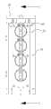
图6是表示本发明的实施例涉及的无菌适配器的立体图。Fig. 6 is a perspective view showing a sterile adapter according to an embodiment of the present invention.
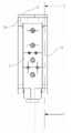
图7是表示在本发明的实施例涉及的无菌适配器上安装手术用器械的状态的主视图。Fig. 7 is a front view showing a state in which a surgical instrument is attached to the sterile adapter according to the embodiment of the present invention.
图8是图7的C-C′的剖视图。Fig. 8 is a sectional view taken along line C-C' of Fig. 7 .
图9是表示在本发明的实施例涉及的无菌适配器上安装手术用器械的状态的剖视图。9 is a cross-sectional view showing a state in which a surgical instrument is attached to the sterile adapter according to the embodiment of the present invention.
图10是表示本发明的实施例涉及的无菌适配器的剖视图。Fig. 10 is a cross-sectional view showing the sterile adapter according to the embodiment of the present invention.
图11是表示本发明的实施例涉及的无菌适配器通过开口被安装在器械支架上的状态的侧视图。Fig. 11 is a side view showing a state in which the sterile adapter according to the embodiment of the present invention is attached to the device holder through the opening.
图12是表示本发明的实施例涉及的无菌适配器被附着在无菌帘上的状态的示意图。Fig. 12 is a schematic diagram showing a state where the sterile adapter according to the embodiment of the present invention is attached to the sterile drapes.
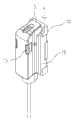
图13是表示在本发明的实施例涉及的无菌适配器上安装手术用器械的状态的立体图。Fig. 13 is a perspective view showing a state in which a surgical instrument is attached to the sterile adapter according to the embodiment of the present invention.
图14是表示本发明的实施例涉及的无菌适配器的分解立体图。Fig. 14 is an exploded perspective view showing the sterile adapter according to the embodiment of the present invention.
图15是表示本发明的实施例涉及的无菌适配器被安装在器械支架上的状态的示意图。Fig. 15 is a schematic diagram showing a state in which the sterile adapter according to the embodiment of the present invention is attached to the device holder.
图16是图15的‘A’的剖视图。FIG. 16 is a sectional view of 'A' in FIG. 15 .
图17是表示本发明的实施例涉及的手术用器械被安装在无菌适配器上的状态的示意图。Fig. 17 is a schematic diagram showing a state in which the surgical instrument according to the embodiment of the present invention is attached to the sterile adapter.
图18是图17的‘B’的剖视图。Fig. 18 is a sectional view of 'B' in Fig. 17 .
图19是示出本发明的第一实施例涉及的根据电特性检测对齐情况的转轮联接结构的示意图。Fig. 19 is a schematic diagram showing the coupling structure of the runners for detecting the alignment according to the electrical characteristics according to the first embodiment of the present invention.
图20是示出本发明的第一实施例涉及的根据电特性检测对齐情况的转轮绝缘状态的示意图。Fig. 20 is a schematic diagram showing the insulation state of the runners according to the electrical characteristic detection of the alignment according to the first embodiment of the present invention.
图21是示出本发明的第二实施例涉及的根据磁特性检测对齐情况的转轮联接结构的示意图。FIG. 21 is a schematic diagram showing a coupling structure of a wheel for detecting alignment based on magnetic properties according to a second embodiment of the present invention.
图22及图23是示出本发明的第三实施例涉及的根据磁特性检测对齐情况的转轮联接结构的示意图。FIG. 22 and FIG. 23 are schematic diagrams showing the coupling structure of the runners according to the magnetic characteristics to detect the alignment according to the third embodiment of the present invention.
图24是示出本发明的第四实施例涉及的根据机械特性对齐转轮的转轮联接结构的立体图。FIG. 24 is a perspective view showing a runner coupling structure for aligning runners according to mechanical characteristics according to a fourth embodiment of the present invention.
图25是示出本发明的第四实施例涉及的根据机械特性对齐转轮的转轮联接结构的主视图。Fig. 25 is a front view showing a runner coupling structure for aligning runners according to mechanical characteristics according to a fourth embodiment of the present invention.
图26是用于说明本发明的第四实施例涉及的根据机械特性对齐转轮的原理的示意图。Fig. 26 is a schematic diagram for explaining the principle of aligning the runners according to the mechanical characteristics according to the fourth embodiment of the present invention.
图27是示出本发明的第五实施例涉及的根据磁特性检测对齐的转轮联接结构的示意图。Fig. 27 is a schematic diagram showing a coupling structure of a wheel for detecting alignment based on magnetic properties according to a fifth embodiment of the present invention.
图28是示出本发明的第五实施例涉及的根据磁特性检测对齐的转轮联接结构的立体图。Fig. 28 is a perspective view showing a coupling structure of a wheel that detects alignment based on magnetic properties according to a fifth embodiment of the present invention.
图29是示出本发明的第六实施例涉及的根据机械特性对齐转轮的转轮联接结构的侧视图。Fig. 29 is a side view showing a runner coupling structure for aligning runners according to mechanical characteristics according to the sixth embodiment of the present invention.
图30是示出本发明的第六实施例涉及的根据机械特性对齐转轮的转轮联接结构的俯视图。Fig. 30 is a plan view showing a runner coupling structure for aligning runners according to mechanical characteristics according to the sixth embodiment of the present invention.
图31是示出本发明的第六实施例涉及的根据机械特性对齐转轮的转轮联接结构的剖视图。31 is a cross-sectional view showing a runner coupling structure for aligning runners according to mechanical characteristics according to a sixth embodiment of the present invention.
图32是示出本发明的第七实施例涉及的根据电特性检测结合情况的医疗设备的联接结构的示意图。Fig. 32 is a schematic diagram showing a connection structure of a medical device that detects a combination according to an electrical characteristic according to a seventh embodiment of the present invention.
图33至图37是示出本发明的第八实施例涉及的医疗设备的联接结构的示意图。33 to 37 are schematic diagrams showing a coupling structure of a medical device according to an eighth embodiment of the present invention.
图38至图41是示出本发明的第九实施例涉及的医疗设备的联接结构的示意图。38 to 41 are schematic diagrams showing a coupling structure of a medical device according to a ninth embodiment of the present invention.
具体实施方式Detailed ways
本发明可以进行多种变化,可具有多种实施例,图示出具体实施例进行详细说明。但是,这并不是将本发明限定于具体的实施方式,而应当理解为包括包含于本发明的思想及技术范围内的所有变换、等同物以及替代物。在说明本发明时有关公知技术的详细说明可能混淆本发明的旨意的情况下,省略该详细说明。The present invention can be changed in many ways, and can have various embodiments, and the specific embodiments are shown in the drawings and described in detail. However, this does not limit the present invention to specific embodiments, and it should be understood that all changes, equivalents, and substitutions included in the idea and technical scope of the present invention are included. In the case where detailed descriptions related to known techniques may obscure the gist of the present invention when describing the present invention, the detailed descriptions will be omitted.
可以使用诸如“第一”、“第二”等术语来描述各种构成要素,但是所述构成要素不受所述术语限制。所述术语仅用于将一个构成要素与另一构成要素进行区分为目的。Various constituent elements may be described using terms such as "first", "second", etc., but the constituent elements are not limited by the terms. The terms are used only for the purpose of distinguishing one constituent element from another constituent element.
本申请中使用的术语仅用于描述具体实施例,并不意在限制本发明。单数表示包括复数表示,除非文章中明确表示。本申请中,诸如“包括”和“具有”等术语意在表示存在说明书的描述中所采用的特征、序号、步骤、操作、构成要素、组件或其组合,而不排除存在或增加一个或多个不同的特征、编号、步骤、操作、构成要素、组件或其组合的可能性。The terms used in the present application are used to describe specific embodiments only, and are not intended to limit the present invention. A singular expression includes a plural expression unless expressly stated in the text. In this application, terms such as "comprising" and "having" are intended to indicate the presence of features, sequence numbers, steps, operations, constituent elements, components or combinations thereof used in the description of the specification, and do not exclude the existence or addition of one or more The possibility of a different feature, number, step, operation, constituent element, component or combination thereof.
下面,参照附图详细说明本发明的实施例,在参照附图进行说明时,相同或相对应的构成要素赋予了相同符号,省略对其的重复说明。Hereinafter, embodiments of the present invention will be described in detail with reference to the drawings. In the description with reference to the drawings, the same or corresponding components are assigned the same symbols, and repeated description thereof will be omitted.
图1是表示本发明的实施例涉及的无菌适配器的分解立体图。参照图1,示出了机器臂1、器械支架3、手术用器械5、无菌适配器10、主体部12、第一面14、第二面17、第一驱动轮30、第一转轮20、第二转轮24、第二驱动轮50。FIG. 1 is an exploded perspective view showing a sterile adapter according to an embodiment of the present invention. With reference to Fig. 1, have shown
本实施例为了对安装在无菌适配器上的转轮向双向、即向与器械支架结合的方向及与手术用器械结合的方向弹性支承,而增加了弹性体,因此器械支架或手术用器械不必使用单独的弹性结构也可将手术用器械安装在器械支架上。In order to elastically support the rotating wheel installed on the aseptic adapter in two directions, that is, to the direction combined with the instrument support and the direction combined with the surgical instrument, an elastic body is added, so the instrument support or the surgical instrument need not Surgical instruments can also be mounted on the instrument holder using a separate elastic structure.
即,与现有的在器械支架上设置弹簧等来对驱动轮赋予弹性的结构不同,在用于将手术用器械结合在器械支架上的无菌适配器上赋予了弹性。That is, unlike the conventional structure in which a spring or the like is provided on the instrument holder to impart elasticity to the drive wheel, elasticity is imparted to the sterile adapter for coupling the surgical instrument to the instrument holder.
本发明涉及的无菌适配器10,在器械支架3上安装手术用器械5的过程中,其设置于器械支架3和手术用器械5之间,利用无菌适配器10将手术用器械5结合在器械支架3。The
本实施例涉及的无菌适配器10由以主体部12为基准向两面露出的第一转轮20和第二转轮24构成,第一转轮20和第二转轮24分别被主体部12弹性支承。即,将主体部12的与器械支架3对置的面作为第一面14,而与手术用器械5对置的面作为第二面17时,第一转轮20从第一面14露出,第二转轮24从第二面17露出,由此,第一、第二转轮20、24自主体部12的两面露出。The
另一方面,第一转轮20及第二转轮24分别通过弹簧等弹性体(图1的‘E’)与主体部12结合,因此,第一、第二转轮20、24通过外力而内陷,当解除外力时通过弹力恢复到原来的位置。即,第一转轮20和第二转轮24彼此连接而一同旋转的同时,通过弹簧等与主体部12结合,从而向分别施压第一转轮20和第二转轮24的方向施加弹力。On the other hand, the
将本实施例涉及的无菌适配器10安装在器械支架3上时,第一面14抵接于器械支架3,而从第一面14露出的第一转轮20与在器械支架3上形成的第一驱动轮30匹配。When the
此外,当在无菌适配器10上安装手术用器械5时,第二面17抵接于手术用器械5,而从第二面17露出的第二转轮24与在手术用器械5上形成的第二驱动轮50匹配。下面,详细说明本实施例涉及的无菌适配器10与器械支架3及手术用器械5结合的方式。In addition, when the
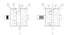
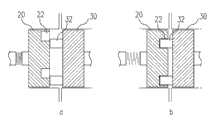
图2是表示本发明的实施例涉及的无菌适配器被安装在器械支架上的状态的示意图,图3是图2的‘A’的剖视图,图4是表示本发明的实施例涉及的手术用器械被安装在无菌适配器上的状态的示意图,图5是图4的‘B’的剖视图。参照图2至图5,示出了器械支架3、手术用器械5、无菌适配器10、主体部12、第一面14、第二面17、第一驱动轮30、突起32、33、第一转轮20、凹槽22、23、第二转轮24、第二驱动轮50。Fig. 2 is a schematic diagram showing a state in which a sterile adapter according to an embodiment of the present invention is mounted on an instrument holder, Fig. 3 is a cross-sectional view of 'A' in Fig. 2 , and Fig. 4 is a diagram showing a surgical adapter according to an embodiment of the present invention A schematic diagram of a state in which the instrument is installed on the sterile adapter, FIG. 5 is a cross-sectional view of 'B' in FIG. 4 . Referring to Fig. 2 to Fig. 5, have shown
首先,观察无菌适配器10与器械支架3之间的结合方式,则在器械支架3上形成的第一驱动轮30上突设有突起32,而与第一驱动轮30对置的第一转轮20上形成有能够插入突起32的凹槽22。First of all, observing the combination mode between the
通过将无菌适配器10安装在器械支架3上,第一驱动轮30与第一转轮20彼此抵接,此时突起32插入到凹槽22中时,第一驱动轮30与第一转轮20匹配,但是突起32未插入到凹槽22中时,突起32推压第一转轮20。如上所述,由于第一转轮20弹性支承在无菌适配器10上,所以当突起32推压第一转轮20时,如图3的a所示,第一转轮20从无菌适配器10的表面(第一面14)被压下。By installing the
这样的因突起32第一转轮20被内陷的状态下,左右旋转第一驱动轮30,则在某处突起32被插入到凹槽22中,由此解除突起32对第一转轮20的施压状态。这样的,随着来自突起32的外力解除,如图3的b所示,第一转轮20由于弹力恢复到原来的位置,从而第一转轮20与第一驱动轮30匹配。In such a state where the
这样,第一转轮20匹配在第一驱动轮30上的状态下旋转第一驱动轮30时,第一转轮20随其联动旋转,从而通过第一驱动轮30将机器人生成的驱动力传递给第一转轮20。In this way, when the first
其次,观察无菌适配器10与手术用手术用器械5之间的结合方式,在第二转轮24上突设有突起33,而在与第二转轮24对置的第二驱动轮50上形成有能够插入突起33的凹槽23。Secondly, observe the combination mode between the
通过将手术用器械5安装在无菌适配器10上,第二驱动轮50与第二转轮24彼此抵接,此时如果突起33插入到凹槽23中时,第二驱动轮50与第二转轮24彼此匹配,但是如果突起33未被插入到凹槽23中时,第二驱动轮50推压突起33,由此第二转轮24也被推压。如上所述,由于第二转轮24弹性支承在无菌适配器10上,所以当突起33推压第二转轮24时,如图5的a所示,第二转轮24从无菌适配器10的表面(第二面17)被压下。By installing the
在第二转轮24被内陷的状态下,左右旋转第一驱动轮30,则与第一驱动轮30匹配的第一转轮20及与第一转轮20连接的第二转轮24联动旋转,由此发生突起33被插入到凹槽22中的情况,从而解除第二转轮24被施压的状态。这样,随着外力的解除,如图5的b所示,第二转轮24由于弹力恢复到原来的位置,从而第二转轮24与第二驱动轮50匹配。In the state where the
这样,第二驱动轮50与第二转轮24匹配的状态下旋转第一驱动轮30时,第一转轮20、第二转轮24及第二驱动轮50随其联动旋转,从而通过第一驱动轮30、第一转轮20及第二转轮24将机器人生成的驱动力传递给第二驱动轮50。In this way, when the
第二驱动轮50可以通过钢丝与手术用器械5末端部结合的执行器连接,如上所述,随着驱动力传递到第二驱动轮50而第二驱动轮50旋转,通过钢丝将驱动力传递给执行器,从而使执行器运行。The
在此,对在第一驱动轮30及第二转轮24上形成突起32、33而在第一转轮20及第二驱动轮50上形成凹槽22、23并彼此匹配的情况进行了说明,但是突起和凹槽并不一定如上所述的形成,也可以在一对转轮的任一方上形成突起而在另一方上形成凹槽,从而相互匹配。Here, the case where the
进一步,并不一定必须在任一个转轮上形成突起而在另一个转轮上形成凹槽的方式匹配,当然可以适用能够使一对转轮彼此匹配的多种机械结构。Further, it is not necessarily necessary to form a protrusion on one wheel and form a groove on the other wheel for matching, and of course various mechanical structures that can make a pair of wheels match each other can be applied.
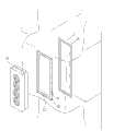
图6是表示本发明的实施例涉及的无菌适配器的立体图,图7是表示在本发明的实施例涉及的无菌适配器上安装器械的状态的主视图,图8是图7的C-C′的剖视图,图9是表示在本发明的实施例涉及的无菌适配器上安装器械的状态的剖视图。参照图6至图9,示出了手术用器械5、无菌适配器10、主体部12、第一板材15、第二板材18、第二转轮24、凹槽23、导轨126、对齐凹槽27、对齐突起28、挡块29、突起33、第二驱动轮50。Fig. 6 is a perspective view showing an aseptic adapter according to an embodiment of the present invention, Fig. 7 is a front view showing a state in which an instrument is attached to the aseptic adapter according to an embodiment of the present invention, and Fig. 8 is a view of C-C' of Fig. 7 Cross-sectional view, FIG. 9 is a cross-sectional view showing a state in which an instrument is attached to the sterile adapter according to the embodiment of the present invention. Referring to Figures 6 to 9, there are shown
本实施例涉及的无菌适配器10的主体部12可以由结合成彼此可分开或接近的一对板材15、18构成。即,主体部12由与第一面14相对应并抵接器械支架3的第一板材15和与第二面17相对应并抵接手术用器械5的第二板材18构成,而第一板材15和第二板材18可结合成彼此分离或接近。The
此时,如图6所示,可以在第二板材18的两侧部设置导轨126,本实施例涉及的导轨126起到提供移动路径使手术用器械5以滑动方式安装在无菌适配器10上的作用。At this time, as shown in FIG. 6 ,
为了使手术用器械5沿导轨126滑移并安装在无菌适配器10上,如图8所示,可以在手术用器械5的端面上形成与导轨126相对应的滑轨结构(参照图8的‘R’)。In order to slide the
另一方面,当以滑动方式将手术用器械5安装在无菌适配器10上时,为了使手术用器械5安装在无菌适配器10上的正确位置,在本实施例涉及的手术用器械5上可形成有对齐(align)单元。即,如图7所示,在手术用器械5的端部内陷地形成有对齐凹槽27时,在第二板材18的一端部上也可以突设有对齐突起28,以便与对齐凹槽27匹配。On the other hand, when installing the
如图7a所示手术用器械5通过滑移而安装在无菌适配器10上时,将手术用器械5移动直至对齐突起28与对齐凹槽27匹配而被安装,从而能够将手术用器械5对齐在正确位置上。When the
本实施例涉及的对齐凹槽27及对齐突起28是起到对齐作用的结构,以便使手术用器械5安装在无菌适配器10上预先指定的位置,因此需要精密制造以防止对齐凹槽27与对齐突起28之间发生多余间隔。The
另一方面,如上所述的向一方向(安装方向)滑动手术用器械5而安装在无菌适配器10上时,为了防止手术用器械5从无菌适配器10上脱落以保持其安装状态,即,为了限制安装的手术用器械5向安装方向的反方向移动,可突设有挡块29。On the other hand, when the
即,在第二板材18的另一端部上设置挡块29,且如图7a所示地移动手术用器械5而安装成如图7b之后,使得挡块29突出,从而防止手术用器械5向反方向脱落。That is, a
为此,本实施例涉及的挡块29可以由弹性体等支承,以便在安装手术用器械5的过程中不从第二板材18突出,而安装完手术用器械5之后突出,从而能够固定手术用器械5。如下所述,也可以使挡块29随着第二板材18接近第一板材15而从第二板材18突出。For this reason, the
另一方面,如上所述,可以在第二转轮24上突设突起33而在第二驱动轮50上形成凹槽23从而使第二驱动轮50与第二转轮24匹配,但是手术用器械5通过滑移而安装在无菌适配器10上时,从第二面突出的突起33可能干扰手术用器械5的移动,从而给滑动方式安装带来困难。On the other hand, as mentioned above, the
此时,如图9所示,主体部12以彼此分离、接近的一对板材15、18构成,所以突起33在第二转轮24上突出的状态下也能够以滑动方式安装手术用器械5。At this time, as shown in FIG. 9 , the
即,如图9的a所示,将第二板材18从第一板材15分离,而在第二转轮24的突起33未从第二板材18的表面突出的状态下安装手术用器械5,安装完手术用器械5之后,如图9的b所示,按压第二板材18,即,使得第二板材18接近第一板材15,从而可以使突起33从第二板材18的表面突出。由此,手术用器械5安装在无菌适配器10上,而第二转轮24可与第二驱动轮50匹配。That is, as shown in a of FIG. 9 , the
另一方面,按压第二板材18使突起33从第二板材18突出时,如果突起33未准确插入到凹槽23中时,参照如图5所述,由于第二转轮24弹性支承在无菌适配器10上,所以第二驱动轮50推压突起33,第二转轮24处于不能从第二板材18突出而被推压的状态,但如上所述,可以在该状态下左右旋转第二转轮24而使突起33与凹槽23匹配。On the other hand, when pressing the
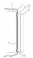
图10是表示本发明的实施例涉及的无菌适配器的剖视图,图11是表示本发明的实施例涉及的无菌适配器通过开口被安装在器械支架3上的状态的侧视图,图12是表示本发明的实施例涉及的无菌适配器被附着在无菌帘上的状态的示意图。参照图10至图12,示出了机器臂1、器械支架3、手术用器械5、无菌帘7、无菌适配器10、主体部12、第一面14、第一板材15、贯穿孔116、第二面17、第二板材18、固定突起119、第一驱动轮30、密封材料34、第一转轮20、第二转轮24、第二驱动轮50、开口72、粘接部74、标记76。Fig. 10 is a cross-sectional view showing an aseptic adapter according to an embodiment of the present invention, Fig. 11 is a side view showing a state where the aseptic adapter according to an embodiment of the present invention is installed on the
如上所述,本实施例涉及的无菌适配器10的主体部12可以由可彼此分离或接近地结合的一对板材15、18构成,此时,在第二板材18上可形成有向第一面14突设的固定突起119,而在第一板材15上穿设有用于收纳固定突起119的贯穿孔116。As mentioned above, the
即,在一对板材15、18上分别形成有固定突起119和贯穿孔116,如图10a所示,一对板材15、18彼此分离的状态下,固定突起119处于收容在贯穿孔116中的状态,如图10的b所示,当一对板材15、18彼此接近时,固定突起119可以贯通贯穿孔116而从主体部12的表面(第一面14)上突出。That is, a pair of
这样,主体部12由一对板材15、18构成,随着一对板材15、18彼此接近使固定突起119从主体部12的表面(第一面14)上突出时,无菌适配器安装在器械支架3上,而随着一对板材15、18彼此接近,固定突起119从无菌适配器10的表面上突出,从而固定突起119对器械支架3的规定位置进行施压。这样突出的固定突起119起到如下所述的将无菌帘7固定在器械支架3上的作用。In this way, the
机器人手术过程中,手术用机器臂被无菌帘(sterile drape)覆盖,但是本实施例涉及的无菌帘7上可穿设有开口72。开口72可以穿设在机器臂上的拆装手术用器械5等外部装置的位置,本实施例涉及的开口72可以穿设在器械支架3部分、即用于将无菌适配器10安装在器械支架3上的位置。During the robotic surgery, the surgical robotic arm is covered by a sterile drape, but the sterile drape 7 involved in this embodiment may be provided with an
通过将本实施例涉及的无菌适配器10安装在器械支架3上,固定突起119从其表面(第一面14)突出,而机器臂1被无菌帘7覆盖的状态下安装无菌适配器10时,突起的固定突起119对无菌帘7的开口72的外周部进行施压,从而无菌帘7紧密固定在器械支架3上。By installing the
此外,与在无菌适配器10上突出的固定突起119相对应地,在器械支架3的周边设置橡胶密封件等密封材料34,则仅通过安装无菌适配器10就能够将无菌帘7固定在机器臂1上。In addition, corresponding to the fixing
即,与开口72的外周部相对应地在器械支架3及/或其周边粘贴弹性材料制成的密封材料34时,通过安装无菌适配器10使固定突起119突起,而固定突起119对无菌帘7的开口72的外周部及与其相应设置的密封材料34进行加压,从而密封材料34被突出的固定突起119加压而下陷。That is, when the sealing
于是,无菌帘7的开口72处于外周部被固定突起119和密封材料34夹住而固定的状态,通过安装无菌适配器10,无菌帘7固定在机器臂1上。Then, the
另一方面,将本实施例涉及的无菌适配器10安装在器械支架3之前,可以先将无菌适配器10附着在无菌帘7的规定位置上,例如上述开口72部分,为此,可在需要附着无菌适配器10的部分(开口72的外周部)形成贴纸(sticker)等粘接部74,并在其周围标出四边形等标记76,从而预先表示出用于附着无菌适配器10的位置。On the other hand, before the
这样预先在无菌帘7上形成粘接部74及标记76时,撕开无菌帘7的贴纸保护膜,将无菌适配器10对齐四边形标记附着在无菌帘7上,从而能够将无菌适配器10准确附着在预先指定的位置、即穿设有开口72的位置。When forming the
此外,将无菌适配器10附着在无菌帘7的指定位置的状态下,将无菌适配器10安装在器械支架3上,从而能够将无菌帘7固定于机器臂1。In addition, the aseptic drapes 7 can be fixed to the
图13是表示在本发明的实施例涉及的无菌适配器上安装器械的状态的立体图。参照图13,示出了手术用器械5、无菌适配器10、主体部12、突出部113、触点133、134。Fig. 13 is a perspective view showing a state in which an instrument is attached to the sterile adapter according to the embodiment of the present invention. Referring to FIG. 13 , a
在本实施例的无菌适配器10上可安装有电手术(Electrosurgery)用的器械或具有电手术功能的器械,此时,需要向手术用器械5提供用于电手术的电源。Instruments for electrosurgery or instruments with electrosurgery functions may be installed on the
即,与为了进行电手术而形成有触点133的手术用器械5对应地,在无菌适配器10上形成有供电用的触点134,在安装手术用器械5的过程中使触点133、134彼此连接,从而可向手术用器械5供电。That is, corresponding to the
例如,手术用器械5可以以滑动方式安装在本实施例涉及的无菌适配器10上,此时,在主体部的以手术用器械5被安装方向的端部,如图13所示,形成有突出部113,从而能够安装手术用器械5。For example, the
此时,在本实施例涉及的突出部113上可形成有用于向手术用器械5供电的触点134,于此相应地,在手术用器械5上也可以形成有触点133。At this time, a
即,以使由手术用机器人提供的电源连接到在无菌适配器10的突出部113上形成的触点133的状态下,安装手术用器械5从而使触点133、134之间连接,所以不必单独连接电源而仅通过安装手术用器械5即可提供电手术所需的电源。That is, in the state where the power supply provided by the surgical robot is connected to the
触点的数量可以根据电手术用器械的类型而做成多种,例如,单极(monopolar)模式的情况可形成一个触点,双级(bipolar)模式的情况可形成两个触点。The number of contacts can be varied according to the type of the electrosurgical instrument. For example, one contact may be formed in the case of a monopolar mode, and two contacts may be formed in a case of a bipolar mode.
图14是表示本发明的实施例涉及的无菌适配器的分解立体图。参照图14,示出了机器臂1、器械支架3、手术用器械5、无菌适配器10、主体部12、第一面14、第二面17、第一驱动轮30、第一转轮20、第二转轮24、第二驱动轮50。Fig. 14 is an exploded perspective view showing the sterile adapter according to the embodiment of the present invention. Referring to Fig. 14 , it shows a
本实施例涉及的无菌适配器10,在器械支架3上安装手术用器械5的过程中设置于其间,手术用器械5利用无菌适配器10与器械支架3结合。The
本实施例涉及的无菌适配器10由以主体部12为基准向两面露出的第一转轮20和第二转轮24构成,而第一、第二转轮20、24分别弹性支承在主体部12上。即,将主体部12的与器械支架3对置的面作为第一面14,与手术用器械5对置的面作为第二面17时,第一转轮20从第一面露出,第二转轮24从第二面17露出,从而第一、第二转轮20、24从主体部12的两面露出。The
另一方面,第一转轮20及第二转轮24分别通过弹簧等弹性体(图14的‘E’)与主体部12结合,因此,第一、第二转轮20、24由于外力而被内陷,当解除外力时由于弹力恢复到原来的位置。即,第一转轮20和第二转轮24彼此连接而一同旋转,并通过弹簧等与主体部12结合,因此第一转轮20和第二转轮构成为向相互推压的方向受到弹力。On the other hand, the
将本实施例涉及的无菌适配器10安装在器械支架3上,则第一面14抵接器械支架3,从第一面14露出的第一转轮20与形成在器械支架3上的第一驱动轮30匹配。When the
此外,在无菌适配器10上安装手术用器械5,则第二面17抵接手术用器械5,从第二面17露出的第二转轮24与形成在手术用器械5上的第二驱动轮50匹配。下面,详细说明本实施例涉及的无菌适配器10与器械支架3及手术用器械5结合的方式。In addition, when the
图15是表示本发明的实施例涉及的无菌适配器被安装在器械支架上的状态的示意图,图16是图15的‘A’的剖视图,图17是表示本发明的实施例涉及的手术用器械被安装在无菌适配器上的状态的示意图,图18是图17的‘B’的剖视图。参照图15至图18,示出了器械支架3、手术用器械5、无菌适配器10、主体部12、第一面14、第二面17、第一驱动轮30、突起32、33、第一转轮20、凹槽22、23、第二转轮24、第二驱动轮50。Fig. 15 is a schematic view showing a state in which the sterile adapter according to the embodiment of the present invention is installed on the instrument holder, Fig. 16 is a cross-sectional view of 'A' in Fig. A schematic diagram of a state in which the instrument is installed on the sterile adapter, FIG. 18 is a cross-sectional view of 'B' in FIG. 17 . Referring to Fig. 15 to Fig. 18, have shown
观察无菌适配器10与器械支架3之间的结合方式,在器械支架3上形成的第一驱动轮30上突设有突起32,而与第一驱动轮30对置的第一转轮20上形成有能够插入突起32的凹槽22。Observing the combination mode between the
通过将无菌适配器10安装在器械支架3上,第一驱动轮30与第一转轮20彼此抵接,此时突起32插入到凹槽22中,则第一驱动轮30与第一转轮20匹配,但是当突起32未插入到凹槽22中时,突起32推压第一转轮20。由于第一转轮20弹性支承在无菌适配器10上,所以突起32推压第一转轮20时,如图16a所示,第一转轮20从无菌适配器10表面(第一面14)被压入。By installing the
这样,第一转轮20因突起32被内陷的状态下,左右旋转第一驱动轮30,则突起32被插入到凹槽22中,由此突起32对第一转轮20的施压状态被解除。随着来自突起32的外力的解除,如图16的b所示,第一转轮20由于弹力恢复到原来的位置,从而使第一转轮20与第一驱动轮30匹配。In this way, when the
在这样使第一转轮20匹配在第一驱动轮30上的状态下旋转第一驱动轮30时,第一转轮20随其联动旋转,从而通过第一驱动轮30将机器人生成的驱动力传递给第一转轮20。When the
其次,观察无菌适配器10与手术用器械5之间的结合方式,在第二转轮24上突设有突起33,而在与第二转轮24对置的第二驱动轮50上形成有能够插入突起33的凹槽23。Secondly, observe the combination mode between the
通过将手术用器械5安装在无菌适配器10上,第二驱动轮50与第二转轮24彼此抵接,此时突起33插入到凹槽23中时,第二驱动轮50与第二转轮24彼此匹配,但是当突起33未插入到凹槽23中时,第二驱动轮50推压突起33,导致第二转轮24被推压。如上所述,由于第二转轮24弹性支承在无菌适配器10上,所以当突起33推压第二转轮24时,如图5的a所示,第二转轮24从无菌适配器10的表面(第二面17)被压入。By installing the
在第二转轮24被内陷的状态下,左右旋转第一驱动轮30,则与第一驱动轮30匹配的第一转轮20及与第一转轮20连接的第二转轮24联动旋转,从而使突起33插入到凹槽22中,由此解除第二转轮24被施压的状态。这样,随着外力的解除,如图18的b所示,第二转轮24由于弹力恢复到原来的位置,从而第二转轮24与第二驱动轮50彼此匹配。In the state where the
在第二驱动轮50与第二转轮24被匹配的状态下旋转第一驱动轮30,则第一转轮20、第二转轮24及第二驱动轮50联动旋转,从而通过第一驱动轮30、第一转轮20及第二转轮24将机器人生成的驱动力传递给第二驱动轮50。When the
第二驱动轮50可以通过钢丝与结合在手术用器械5的末端部的执行器连接,如上所述的随着驱动力传递到第二驱动轮50而第二驱动轮50旋转,通过钢丝将驱动力传递给执行器,从而使执行器运行。The
在此,对在第一驱动轮30及第二转轮24上形成突起32、33而在第一转轮20及第二驱动轮50上形成凹槽22、23并彼此匹配的情况进行了说明,但是突起和凹槽并不一定要如上所述的形成,也可以在一对转轮的任一方上形成突起而在另一方上形成凹槽的方式彼此匹配。Here, the case where the
进一步,并不一定必须在任一个转轮上形成突起而在另一个转轮上形成凹槽的方式匹配,当然可以适用能够使一对转轮彼此匹配的多种机械结构。Further, it is not necessarily necessary to form a protrusion on one wheel and form a groove on the other wheel for matching, and of course various mechanical structures that can make a pair of wheels match each other can be applied.
还有,在后述的转轮的联接结构是第一转轮20、第二转轮24、第一驱动轮30、第二驱动轮50彼此联接的结构,并非仅适用于特定的转轮结构。当然,本实施例涉及的转轮联接结构并不只用于医疗设备中,在多个转轮结合的结构中,只要是能够适用检测对齐情况的技术的结构或能够传递规定力的结构,本实施例均可适用。In addition, the coupling structure of the runners described later is a structure in which the
此外,在后述的实施例中的本体部是表示用于转轮结合的本体,可以是器械支架3、手术用器械5、主体部12等。另外,驱动轮和从动轮是用于区分转轮的统称,分别可以是第一转轮20、第二转轮24、第一驱动轮30、第二驱动轮50等。即,驱动轮和从动轮是相对概念,可以指称相同的转轮。例如,手术用器械5上所具有的第二驱动轮50,在驱动所述执行器时作为驱动轮,而随着在器械支架3上所具有的第一驱动轮30的驱动而驱动时作为从动轮。用于驱动驱动轮及从动轮的动力源可以由手术用机器臂1提供。In addition, the main body in the embodiments described later refers to a main body used for wheel coupling, and may be the
此外,上述内容主要说明了第一转轮20和第二转轮24由单独构件构成的情况,但是后述的实施例并不仅限于这些结构,当然可以由同一结构实现,在两面上分别形成所述突起及凹槽,从而与第一驱动轮30和第二驱动轮50结合。此外,后述的实施例主要说明与在先说明的实施例的不同点。In addition, the above content mainly describes the situation that the
图19是示出本发明的第一实施例涉及的根据电特性检测对齐的转轮联接结构的示意图。参照图19,示出了第一转轮20、凹槽22、23、第二转轮24、第一驱动轮30、突起32、33、匹配检测部35、触点43、44、第二驱动轮50。后述的有关各转轮的结构及功能的说明也可适用于具有不同名称的转轮。Fig. 19 is a schematic diagram showing a coupling structure of a runner for detecting alignment based on electrical characteristics according to the first embodiment of the present invention. Referring to Fig. 19, it shows the
本实施例涉及的转轮联接结构,其特征在于,利用电特性检测转轮是否对齐。即,多个转轮彼此联接时,触点彼此连接而通电,由传感器检测到经通电而变化的电特性,从而能够检测出转轮被联接。The wheel coupling structure involved in this embodiment is characterized in that electrical characteristics are used to detect whether the wheels are aligned. That is, when a plurality of runners are connected to each other, the contacts are connected to each other and energized, and the sensor detects the electrical characteristic changed by the energization, so that it is possible to detect that the runners are connected.
如上所述的第一转轮20、第二转轮24、第一驱动轮30、第二驱动轮50可分别向不同方向旋转,而且彼此联接时在各转轮上形成的突起32、33可能未插入到凹槽22、23中。因此,需要根据各突起32、33插入到凹槽22、23中而检测转轮彼此是否对齐的技术。本实施例是利用电特性来检测转轮是否对齐的技术。The above-mentioned
本实施例通过检测各转轮匹配时发生的电变化判断其匹配情况。在此,检测匹配时发生的电变化的方法有多种。根据本发明的一实施例,可以包括通过检测各转轮匹配时发生的电变化检测匹配情况的匹配检测部,匹配检测部可以通过检测电信号、电阻值、电流值、电压值等电变化来检测匹配情况。In this embodiment, the matching conditions of the runners are judged by detecting the electrical changes that occur when the runners are matched. Here, there are various methods for detecting the electrical change that occurs at the time of matching. According to an embodiment of the present invention, it may include a matching detection unit that detects the matching situation by detecting the electrical changes that occur when the wheels are matched. The matching detection unit can detect electrical changes such as electrical signals, resistance values, current values, and voltage values. Check for matches.
例如,匹配检测部可以包括:光源,设在一个转轮的一面上;光检测单元,用于检测光源的光变化;改变单元,设在所述转轮或与其对应的另一转轮的一面上,改变光源的光特性。光源的光特性可以随着反射、折射、衍射、干涉而变化,而且变化的光特性可以是光的行进方向、颜色、亮度、色坐标、色温、衍射图样、干涉图样等。例如,改变单元为用于反射光的单元的情况,当在这些结构上转轮彼此未匹配而隔开规定间距时,光检测单元检测不到光源的光,而转轮彼此匹配时,光源的光被反射单元反射,所以光检测单元可以通过检测反射光来检测出转轮彼此匹配。在此,光检测单元可以是光电二极管等,反射单元可以是反射镜等。For example, the matching detection part may include: a light source, arranged on one side of a rotating wheel; a light detection unit, used to detect the light change of the light source; a changing unit, arranged on one side of the rotating wheel or another corresponding rotating wheel On, change the light characteristics of the light source. The light characteristics of the light source can change with reflection, refraction, diffraction, and interference, and the changed light characteristics can be the direction of travel, color, brightness, color coordinates, color temperature, diffraction pattern, interference pattern, etc. of light. For example, in the case where the changing unit is a unit for reflecting light, when the wheels are not matched with each other and are separated by a predetermined distance on these structures, the light detection unit cannot detect the light of the light source, and when the wheels are matched with each other, the light of the light source The light is reflected by the reflection unit, so the light detection unit can detect that the wheels are matched with each other by detecting the reflected light. Here, the light detection unit may be a photodiode or the like, and the reflection unit may be a mirror or the like.
下面主要说明在转轮结合电阻并通过检测电阻值的变化来检测是否匹配的情况,但是本发明可适用如上所述的通过检测根据光检测的电磁变化来检测匹配情况,或利用其它电磁特性的变化检测匹配情况的多种方法。例如,本实施例也可以利用如电阻(resistance)变化、电容(capacitance)变化、电感(inductance)变化等利用被动(passive)元件的电磁变化或其它主动(active)元件检测匹配情况。The following mainly describes the case where a resistance is combined with a wheel and the matching is detected by detecting the change of the resistance value, but the present invention can be applied to the detection of the matching situation by detecting the electromagnetic change according to the light detection as described above, or using other electromagnetic characteristics. Variety of methods for change detection matching situations. For example, this embodiment may also use electromagnetic changes of passive (passive) elements or other active (active) elements to detect matching conditions, such as resistance (resistance) changes, capacitance (capacitance) changes, inductance (inductance) changes, etc.
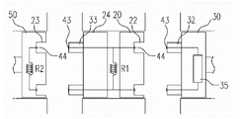
首先,说明第一转轮20与第一驱动轮30的结合关系。由于第一驱动轮30上突出的突起32插入到在第一转轮20上形成的凹槽22中,所以第一驱动轮30与第一转轮20彼此联接。突起32及凹槽22的数量可以是一个或多个,且并不特别限定其形成位置,图19中说明分别具有两个的情况。First, the connection relationship between the
在突起32的一端上形成有触点43,而在凹槽22的内侧面上形成有触点44,当突起32插入到凹槽22中时,两个触点43、44彼此电连接。触点43、44在突起32或凹槽22上形成的位置只要是彼此能够连接的位置不做特别限定,例如,可以是突起32的末端部、中间部位等不同位置。A
各突起32的触点43与匹配检测部35连接,匹配检测部35用于检测突起32的触点43是否与凹槽22的触点44接触。匹配检测部35可以是接收电信号并进行分析从而输出目前状态信息的装置。The
例如,匹配检测部35可以通过检测电阻值并分析被检测到的电阻值而判断触点43、44的接触情况。即,在图19所示的状态下,突起32的触点43彼此隔开,所以匹配检测部35测量的电阻值为无穷大(∞)。但是,当突起32插入到凹槽22中而触点43、44彼此接触时,匹配检测部35所测量的电阻值相当于连接在凹槽22上形成的触点44之间的第一电阻R1的电阻值。For example, the matching
因此,匹配检测部35可以相互比较被测量的电阻值或与未接触状态的电阻值进行比较,从而判断触点43、44的接触情况。在此,说明了匹配检测部35通过检测电阻值判断是否接触的情况,但是本发明也可以通过测量其它电特性例如电流值、电压值等判断接触情况。所以,匹配检测部35可以是电阻测量仪及电流测量仪及电压测量仪中的任一个以上。判断结果可通过规定单元例如声音、光、振动等输出,或也可以作为用于启动机器臂1正常运行的信息而使用。Therefore, the matching
其次,说明第二转轮24与第二驱动轮50的结合关系。在第二转轮24上突出的突起33插入到在第二驱动轮50上形成的凹槽23中,从而使第二转轮24与第二驱动轮50彼此联接。突起33的一端上形成有触点43,而在凹槽23的内侧面上形成有触点44,当突起33插入到凹槽23中时,突起33与凹槽23的两个触点43、44彼此电连接。Next, the coupling relationship between the
此时,突起32与凹槽22的两个触点43、44及突起33与凹槽23的两个触点43、44彼此接触,从而形成具有新的合成电阻的电路。即,连接在凹槽22的两个触点43之间的第一电阻R1与连接在凹槽23的两个触点43之间的第二电阻R2彼此并联,所以新的合成电阻值R的计算公式如下。At this time, the two
公式1
此时,匹配检测部35能够通过检测合成电阻值R而检测出器械支架3、无菌适配器10及手术用器械5彼此正常联接。At this time, the matching
另外,此时由于只有突起32插入到凹槽22中时的电阻值R1与突起33也同时插入到凹槽23中时的电阻值R彼此不同,所以匹配检测部35可以利用它来测量各转轮的联接状态。例如,R1为100Ω,R2为0Ω时,只有突起32与凹槽22的两个触点43、44接触时,匹配检测部35测量到的电阻值为100Ω。但是,在该状态下,突起33与凹槽23的两个触点43、44也彼此接触时,匹配检测部35测量到的电阻值为0Ω。因此,利用这种电特性,能够更准确地检测到各转轮联接状态。In addition, at this time, since only the resistance value R1 when the
在此,第一驱动轮30、第一转轮20、第二转轮24及第二驱动轮50以其名称进行了说明,但是也可以分别依次称为主动轮、第一从动轮、第二从动轮及第三从动轮而进行说明。Here, the
图20是示出本发明的第一实施例涉及的根据电特性检测对齐情况的转轮绝缘状态的示意图。参照图20,示出了第一驱动轮30、突起32、32′、触点43、43′、匹配检测部35。Fig. 20 is a schematic diagram showing the insulation state of the runners according to the electrical characteristic detection of the alignment according to the first embodiment of the present invention. Referring to FIG. 20 , there are shown the
本实施例是专用于第一驱动轮30由铁等导体形成时使突起32、32′彼此绝缘的结构的技术。第一驱动轮30的开放的外表面整体由导体形成,在一面上形成有突出的突起32′。在第一驱动轮30的开放的外表面上与突起32相应地穿设有孔,突起32插入到该孔中而露出触点43。因此,即便第一驱动轮30由导体形成,触点43、43′也能够保持彼此绝缘状态。This embodiment is a technique dedicated to the structure of insulating the
图21是示出本发明的第二实施例涉及的根据磁特性检测对齐的转轮联接结构的示意图。参照图21,示出了器械支架3、手术用器械5、第一驱动轮30、磁性传感器37、第二驱动轮50、磁铁56、存储单元58。Fig. 21 is a schematic diagram showing a coupling structure of a wheel that detects alignment based on magnetic properties according to a second embodiment of the present invention. Referring to FIG. 21 , it shows the
本实施例涉及的转轮联接结构具有利用磁特性检测转轮的对齐情况的特性。即,多个转轮彼此联接时,通过检测附着在指定转轮上的磁铁的排列方向来检测转轮的对齐状态,从而能够检测转轮的联接情况及正常对齐情况。The runner coupling structure involved in this embodiment has the characteristic of detecting the alignment of the runners by using magnetic properties. That is, when a plurality of wheels are coupled to each other, the alignment state of the wheels can be detected by detecting the alignment direction of the magnets attached to the specified wheels, so that the coupling status and normal alignment of the wheels can be detected.
在第一驱动轮30与第二驱动轮50彼此结合的各面上形成有规定的凹凸,这些凹凸可分别指称为第一凹凸及第二凹凸。形成在第一驱动轮30的一个面上的第一凹凸与形成在第二驱动轮50上的第二凹凸进行凹凸结合,从而第一驱动轮30与第二驱动轮50彼此联接。On each surface where the
在此,第一凹凸及第二凹凸可以是扇状的凹凸。如图所示,扇状的凹凸从中心部呈放射状延伸而构成凹与凸交替形成的凹凸。第一驱动轮30与第二驱动轮50与其旋转程度无关地可通过这种扇状凹凸彼此结合。即,由于扇状凹凸交替形成有多个凹和凸,所以一侧的转轮即使以保持规定角度的状态下彼此结合,也可以进行凹凸结合。Here, the first unevenness and the second unevenness may be fan-shaped unevenness. As shown in the figure, the fan-shaped unevenness extends radially from the center to form unevenness in which concaves and convexes are alternately formed. The
在第二驱动轮50的一面上附着有按规定方向排列的磁铁56。在第一驱动轮30侧所具有的磁性传感器37通过检测磁铁56的磁特性来检测其排列状态。在此,示出了磁铁56与磁性传感器37位于第二驱动轮50与第一驱动轮30的各面中心部位的情况,但是本发明并不限定于这些特定位置,只要是磁性传感器37能够检测到磁铁56的排列的位置均可适用于本发明。
在与第二驱动轮50联接时,磁性传感器37可以通过检测磁铁56的极性(N极和S极)判断其旋转程度。例如,在第二驱动轮50的初期设定状态下,磁铁56排列成N极和S极相对于规定基准线呈垂直或水平,而且如上所述,第二驱动轮50即使旋转规定角度的状态下也能够与第一驱动轮30结合,所以磁性传感器37可通过测量磁铁56的旋转角检测第二驱动轮50的旋转程度。When coupled with the
机器臂1运行时可参考检测到的第二驱动轮50的旋转角,从而校正第二驱动轮50的运行。例如,假定执行器所具有的一对钳口彼此咬合的状态为初期设定状态,而通过钢丝与该状态的执行器结合的第二驱动轮50处于未旋转状态,且磁铁56以平行状态排列在手术用器械5的角落时,当第二驱动轮50联接在第一驱动轮30上时以旋转规定角度的状态被联接时,磁性传感器37可通过检测其旋转角了解执行器的状态信息,通过校正该状态信息可精确地控制执行器。The detected rotation angle of the
另一方面,一开始磁铁56附着在第二驱动轮50上时如以无误差的正常状态附着的情况下,如上所述,通过测量磁铁56的旋转角导出第二驱动轮50的旋转信息的方式看起来合理,但是制作时当磁铁56附着在第二驱动轮50上时具有规定的排列误差时,这些旋转信息导出程序变得毫无意义。所以,需要测量磁铁56附着在第二驱动轮50上后极性是否以正常状态排列附着,并存储测量的信息,而在实际使用时活用这些测量信息。On the other hand, when the
存储单元58用于存储这些磁铁56排列的误差信息。即,制作手术用器械5时,在第二驱动轮50的一面上附着或形成磁铁56之后,测量其极性的排列状态,从而生成误差信息,并将该信息存储在存储单元58。存储单元58可作为用于存储在手术用器械5的一侧上附着磁铁56并制作的各手术用器械的固有信息的介质而活用。在此,存储单元58可以是如RFID等能够存储信息的介质。The
在器械支架3侧具有存储单元58的读写器,例如RFID读写器(未图示)。RFID读写器从存储单元58接收磁铁56的排列误差信息,并将该信息传送给机器臂1的控制部或存储在规定存储部,机器臂1的控制部在操作手术用器械5时参考排列误差信息来修正误差,从而校正手术用器械5的动作。例如,当存储单元58中存储有磁铁56旋转5度附着的排列误差信息时,机器臂1的控制部可以参考该排列误差信息,并校正-5度来控制手术用器械5的动作。There is a reader-writer of the
图22及图23是示出本发明的第三实施例涉及的根据磁特性检测对齐情况的转轮联接结构的示意图。参照图22及图23,示出了器械支架3、手术用器械5、凹槽23、第一驱动轮30、突起32、磁性传感器37、第二驱动轮50、磁铁56。主要说明与上述的不同点。FIG. 22 and FIG. 23 are schematic diagrams showing the coupling structure of the runners according to the magnetic characteristics to detect the alignment according to the third embodiment of the present invention. Referring to FIG. 22 and FIG. 23 , the
本实施例涉及的转轮联接结构利用如上所述的磁特性检测转轮的对齐情况,其特征在于,通过确定突起32的数量而限制第二驱动轮50联接时的旋转角,从而能够减小转轮对齐的误差。The wheel coupling structure involved in this embodiment utilizes the above-mentioned magnetic characteristics to detect the alignment of the wheels, and is characterized in that the rotation angle of the
在第一驱动轮30的开放面上形成有多个突起32,而在第二驱动轮50的开放面上形成有能够插入突起32的凹槽23。在此,突起32可以是所述第一凹凸,凹槽23可以是所述第二凹凸。A plurality of
形成在第一驱动轮30上的突起32可以是纵剖面为圆、椭圆(包含椭圆的部分曲线)、多边形等的圆锥体、椭圆锥体、角锥体(多角锥体)等。以圆锥体、椭圆锥体、角锥体等实现的各突起32抵接于邻接的突起32的底面,因此与转轮的旋转程度无关地可插入到第二驱动轮50的凹槽23中。The
例如,如图所示,形成四个形状及大小相同且底面彼此抵接于邻接突起32、并紧靠第一驱动轮30的开放面边框的突起32的情况下,在第二驱动轮50的初期设定状态下与第一驱动轮32匹配时,旋转的最大误差角为45度(-45度至+45度)。即,突起32的最尖端指向凹槽23与凹槽23彼此相交的点时,第二驱动轮50最多旋转45度后与第一驱动轮30匹配。For example, as shown in the figure, when four
因此,根据本实施例,可将第二驱动轮50的旋转误差范围限制在特定范围内。这些误差范围可根据突起32的数量决定。例如,突起32的数量为5个时,误差角为36度(-36度至+36度),突起32的数量为N个时,误差角为180/n度(-180/n度至+180/n度)。虽然,在上述中假设具有相同大小及形状的突起32的情况进行了说明,但本实施例并不限定于这些结构,突起32的大小及形状也可以彼此不同。Therefore, according to the present embodiment, the rotation error range of the
在第二驱动轮50上附着有按规定方向排列的磁铁56,而第一驱动轮30具有用于检测磁铁56的磁性传感器37。磁性传感器37的数量及结合位置可根据磁铁56的结合位置决定。例如,如图所示,磁铁56设在第二驱动轮50的一个凹槽23内时,磁性传感器37可分别设在第一驱动轮30上形成的四个突起32上。此外,磁铁56也可以设在凹槽23外部的第二驱动轮50上,磁性传感器37可在突起32的外部附着在第一驱动轮30上,或分别设在器械支架3的一侧,例如四个角落上(参照图23)。
在此,磁性传感器37的数量可以与突起32的数量相同,或其数量之差小于等于2,磁铁56的数量可以小于磁性传感器的数量。当第一驱动轮30与第二驱动轮50彼此匹配时,磁性传感器37可通过检测磁铁56的磁场来检测磁铁56的位置、其排列方向及匹配情况。Here, the number of
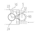
图24及图25是示出本发明的第四实施例涉及的根据机械特性对齐转轮的转轮联接结构的立体图及主视图,图26是用于说明本发明的第四实施例涉及的根据机械特性对齐转轮的原理的示意图。参照图24至图26,示出了手术用器械5、无菌适配器10、主体部12、第一板材15、第二板材18、凹槽23、第二转轮24、引导单元25、对齐凹槽27、对齐突起28、突起33、第二驱动轮50。Fig. 24 and Fig. 25 are perspective views and front views showing the runner coupling structure according to the mechanical characteristics of the fourth embodiment of the present invention, and Fig. 26 is used to illustrate the fourth embodiment of the present invention according to Schematic illustration of the principle of mechanically aligned runners. 24 to 26, there are shown
本实施例涉及的转轮联接结构具有利用机械特性对齐需要联接的转轮的特征。即,根据本实施例,讲需要联接的转轮上形成的突起沿着形成有要插入的凹槽的方向对齐,从而能够对齐转轮。The runner coupling structure involved in this embodiment has the feature of using mechanical properties to align runners to be coupled. That is, according to the present embodiment, the protrusions formed on the wheels to be coupled are aligned in the direction in which the grooves to be inserted are formed, so that the wheels can be aligned.
参照图24,在所述无菌适配器10上突出地形成有漏斗状的引导单元25。在此,主要说明无菌适配器10,但如上所述的本实施例涉及的结构也可以在器械支架3及手术用器械5上实现,可以将这些统称为本体部。Referring to FIG. 24 , a funnel-shaped
引导单元25形成在手术用器械5以滑动方式插入的无菌适配器10的一侧上,可具有接近第二转轮24其宽度变窄的形状。突起33和凹槽23向一方向延伸地形成,凹槽23的形状为能够与突起33匹配的形状。The
参照图25及图26,手术用器械5以滑动方式插入时,在第二驱动轮50上形成的突起33从引导单元25受到偏心旋转力,从而与在第二转轮24上形成的凹槽23的方向相应地对齐。Referring to Fig. 25 and Fig. 26, when the
在此,手术用器械5以滑动方式安装在无菌适配器10上时,为了使手术用器械5安装在无菌适配器10的正确位置上,在本实施例涉及的手术用器械5上可形成有对齐(align)单元。即,如图25所示,在手术用器械5的端部内陷地形成对齐凹槽27时,在第二板材18的一端部上也可以突设有能够与对齐凹槽27匹配的对齐突起27。Here, when the
如图25所示,将手术用器械5滑移而安装在无菌适配器10上时,直至对齐突起28与对齐凹槽27匹配为止移动手术用器械5而进行安装,从而能够将器械对齐在正确位置上。本实施例涉及的对齐凹槽27及对齐突起28能够起到对齐作用,以使手术用器械5安装在无菌适配器10上的预先指定的位置,因此需要精心制造以避免对齐凹槽27与对齐突起28之间产生多余间隔。As shown in Figure 25, when the
参照图26,在第二驱动轮50上形成的突起33以偏心方式突出形成于第二驱动轮50的一部分上。偏心是某种物体的中心偏向于一侧而中心未对齐的状态,当突起33在旋转状态下通过引导单元25时,突起33由于引导单元25的两个羽翼中的任一羽翼的阻力而旋转。Referring to FIG. 26 , the
由于引导单元25的一端的宽度宽而向第二转轮24方向的另一端的宽度窄,所以所述阻力成为对突起33的偏心旋转力,从而突起33旋转至能够插入到凹槽23中的状态。在此,引导单元25另一端的内侧宽度可以与凹槽23的宽度相同或几乎相同。根据本实施例,突起33根据引导单元25提供的偏心旋转力而旋转,而与其相应地,第二驱动轮50旋转,从而第二驱动轮50可以以最初设定状态与第二转轮24匹配。Since the width of one end of the
图27是示出本发明的第五实施例涉及的根据磁特性检测对齐情况的转轮联接结构的示意图,图28是示出本发明的第五实施例涉及的根据磁特性检测对齐情况的转轮联接结构的立体图。参照图27及图28,示出了机器臂1、器械支架3、手术用器械5、无菌适配器10、主体部12、第一面14、第二面17、第一转轮20、凹槽22、23、第二转轮24、第一驱动轮30、突起32、33、磁性传感器37、磁铁41、42、56、第二驱动轮50。Fig. 27 is a schematic diagram showing the coupling structure of the rotating wheel according to the magnetic characteristic detection alignment according to the fifth embodiment of the present invention, and Fig. 28 is a schematic diagram showing the rotating wheel coupling structure according to the magnetic characteristic detection alignment according to the fifth embodiment of the present invention Stereo view of the wheel connection structure. With reference to Fig. 27 and Fig. 28, have shown
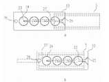
本实施例涉及的转轮联接结构利用磁特性检测转轮的对齐情况,可以利用一个磁性传感器37检测多个转轮的对齐情况。即,在第一转轮20与第二转轮24彼此不相对的两个面上形成的突起32与凹槽23旋转90度,从而可使用设在第一驱动轮30侧的一个磁性传感器37检测第一驱动轮30、第一转轮20、第二转轮24及第二驱动轮50的对齐情况。突起32与凹槽23的延伸方向形成的角度可以为90度、180度或其它指定角度,下面主要说明90度的情况。The wheel coupling structure involved in this embodiment uses magnetic properties to detect the alignment of the wheels, and one
另外,在此,主要说明第一转轮20与第二转轮24彼此不同的情况,但本实施例并不限定于这些结构,例如,在一个转轮的一面上形成突起32和磁铁41,而在另一面上形成凹槽23和磁铁42时,也同样可以根据所说明的原理进行动作。In addition, here, the case where the
观察转轮的联接作业及对齐检测作业,首先,第一驱动轮30与第一转轮20匹配及联接,而磁性传感器37通过检测磁铁41判断第一转轮20是否正常对齐。其次,第一驱动轮30旋转90度使第一转轮20及与其联接的第二转轮24旋转90度,由此磁性传感器37能够检测上述在第二转轮24上相对于磁铁41旋转指定角度而附着的磁铁42,从而检测旋转程度及对齐程度。之后,第二驱动轮50与第二转轮24匹配,而磁性传感器37可通过检测附着在第二驱动轮50上的磁铁56判断第二驱动轮50的对齐状态。在此,可以省去第二转轮24上的磁铁42及附着在第二驱动轮50上的磁铁56中的任一磁铁,此时,磁性传感器37可以仅检测附着的任一磁铁来测定第二驱动轮50的对齐状态。Observe the connection operation and alignment detection operation of the runners. Firstly, the
根据这种结构,可以利用一个磁性传感器37检测多个转轮的对齐状态,从而具有减少体积及成本的效果,此外,当无菌适配器10的宽度做成较小时,具有可提高检测精度的优点。According to this structure, one
图29至图31是示出本发明的第六实施例涉及的根据机械特性对齐转轮的转轮联接结构的侧视图、俯视图及剖视图。参照图29至图31,示出了手术用器械5、无菌适配器10、凹槽23、第二转轮24、突起33、第二驱动轮50、滑轮(pulley)55、导销61。下面主要说明与上述的不同点。29 to 31 are side views, top views and cross-sectional views showing the runner coupling structure for aligning the runners according to the mechanical characteristics according to the sixth embodiment of the present invention. Referring to FIGS. 29 to 31 , there are shown
本实施例涉及的转轮联接结构利用与上述不同的机械特性对齐需要联接的转轮。即,根据本实施例,所述引导单元利用销状导销使用来联接的转轮上形成的突起向形成有用于插入的凹槽的方向对齐,从而能够对齐转轮。The runner coupling structure involved in this embodiment utilizes mechanical characteristics different from those described above to align the runners to be coupled. That is, according to the present embodiment, the guide unit aligns the protrusions formed on the runners coupled using the pin-like guide pins toward the direction in which the grooves for insertion are formed, thereby enabling alignment of the runners.
参照图29、在图29的A方向观看的图30及图29的B的剖视图的图31,在与第二驱动轮50对置的第二转轮24的一面上或在无菌适配器10上形成有导销61,该导销61用于使第二驱动轮50的突起33旋转而插入到第二转轮24的凹槽23中而形成对齐。可以在两侧形成多个导销61,以便第二驱动轮50的突起33能够从它们之间通过,导销61之间的宽度大致相同或大于突起33的宽度,具有能够使突起33从它们之间通过的宽度。滑轮(pulley)55随着第二驱动轮50的旋转而旋转,从而控制手术用器械5的轴、执行器等的运动。Referring to FIG. 29 , FIG. 30 viewed in the A direction of FIG. 29 and FIG. 31 of the cross-sectional view of B in FIG. A
参照图30中的放大部分C,在第二驱动轮50上形成的突起33以偏心方式突出地形成于第二驱动轮50的一部分上。如上所述,偏心是某种物体的中心偏向于一侧而中心彼此未对齐的状态,所以当突起33在旋转的状态下通过导销61时,突起33因与导销61相撞而产生的阻力而进行旋转。当导销61之间的宽度与突起33的宽度相同或几乎相同时,突起33旋转至可插入凹槽23的状态。Referring to enlarged part C in FIG. 30 , the
根据本实施例,突起33根据导销61提供的偏心旋转力而旋转,而与其相应地,第二驱动轮50旋转,从而第二驱动轮50可以以最初设定状态与第二转轮24匹配。According to the present embodiment, the
图32是示出本发明的第七实施例涉及的根据电特性检测结合的医疗器械的联接结构的示意图。参照图32,示出了器械支架3、手术用器械5、无菌适配器10、第一转轮20、第二转轮24、第一驱动轮30、第二驱动轮50、触点63、64、结合检测部65。Fig. 32 is a schematic diagram showing a coupling structure of a medical device that detects coupling based on electrical characteristics according to the seventh embodiment of the present invention. With reference to Fig. 32, have shown
本实施例涉及的医疗器械的联接结构利用电特性检测医疗器械的结合情况。即,所述转轮联接结构相同地可检测多个医疗器械彼此联接时产生的电变化,从而判断其结合情况。The connection structure of the medical device involved in this embodiment uses electrical characteristics to detect the combination of the medical device. That is, the rotating wheel coupling structure can also detect electrical changes generated when multiple medical instruments are coupled to each other, thereby judging their coupling status.
本实施例可以利用通过检测所述电变化检测转轮的对齐情况的技术来检测医疗器械的联接情况。所以所述实施例的内容可以套用在本实施例中,根据每个结构及功能的不同具体联接结构可以不同。即,在所述实施例中有关转轮及匹配检测部等的说明,可以分别适用在本实施例的医疗器械及结合检测部等上。下面主要说明与上述的不同点。In this embodiment, the technology of detecting the alignment of the rotating wheels by detecting the electrical changes can be used to detect the connection of the medical device. Therefore, the content of the above embodiments can be applied in this embodiment, and the specific connection structure can be different according to the structure and function of each structure. That is, the descriptions about the rotating wheel, the matching detection unit, etc. in the above-mentioned embodiment can be applied to the medical device, the combination detection unit, etc. of the present embodiment, respectively. Differences from the above are mainly described below.
本实施例涉及的医疗器械可以是器械支架3、手术用器械5、无菌适配器10等。除此之外,本实施例也可以适用在彼此结合而动作的其它各种医疗器械的结合结构上。The medical instruments involved in this embodiment may be
参照图32,以器械支架3、无菌适配器10、手术用器械5的顺序结合。由于三种医疗器械结合,所以结合面有4个,将这些称为器械支架3的一面、无菌适配器10的一面及另一面、手术用器械5的一面。Referring to FIG. 32 , the
在器械支架3的一面上形成有多个第一触点63,与器械支架3的一面结合的无菌适配器10的一面上形成有多个第二触点64,在无菌适配器10的另一面上形成有多个第三触点63,与无菌适配器10的另一面结合的手术用器械5的一面上形成有多个第四触点64。并不特别限定各触点63、64在各面上的形成位置,可以形成在彼此能够电连接的位置上。A plurality of
如上所述,当器械支架3与无菌适配器10结合时各触点63、64连接,而无菌适配器10与手术用器械5结合时各触点63、64连接,根据结合对象构成彼此不同的电路,根据各电阻R3、R4总电阻值也不同,因此设在器械支架3侧的结合检测部65可以通过测量这些电阻值来检测各医疗器械的结合情况。利用上述方式不仅可以检测器械支架3、无菌适配器10及手术用器械5的联接情况,也可以检测所述各驱动轮与从动轮的联接情况。As described above, when the
图33至图37是示出本发明的第八实施例涉及的医疗器械的联接结构的示意图。具体为,图33是手术用器械5的立体图,图34是无菌适配器10的立体图,图35是手术用器械5与无菌适配器10结合状态的侧视图,图36是手术用器械5与无菌适配器10结合状态的主视图,图37是图36的C-C线的剖视图。参照图33至图37,示出了手术用器械5、无菌适配器10、第一弹性单元11、引导槽16、器械引导部19、挡块29、引导突起59、导销61。主要说明与所述实施例的不同点。33 to 37 are schematic diagrams showing a coupling structure of a medical device according to an eighth embodiment of the present invention. Specifically, FIG. 33 is a perspective view of the
本实施例在转轮联接结构中,提供不仅能够稳固结合转轮而且使用者可容易拆装转轮的结构。即,本实施例具有如下特点,即,在附着有转轮的医疗器械的行进方向上设置引导装置及挡块,从而能够方便稳定地移动及结合转轮,拆装时利用弹性单元从而能够实现多种拆装方向。在此,说明了手术用器械5与无菌适配器10结合的状态,但本实施例也可以适用于无菌适配器10与器械支架3结合的情况及/或手术用器械5与器械支架3结合的情况。In this embodiment, in the connection structure of the runners, not only the runners can be firmly combined, but also the runners can be easily disassembled by the user. That is to say, this embodiment has the following characteristics, that is, a guide device and a stopper are provided in the direction of travel of the medical device attached with the runner, so that the runner can be moved and combined conveniently and stably, and the elastic unit can be used for disassembly and assembly. Multiple disassembly directions. Here, the state in which the
手术用器械5的导销59沿着在器械引导部19的内侧形成的引导槽16移动,从而转轮彼此结合。参照图35,手术用器械5以导销59被收容在引导槽16的状态下向B的反方向移动而与无菌适配器10结合。此时,手术用器械5的转轮与无菌适配器10的转轮匹配时,挡块29起到阻止手术用器械5向B方向移动的阻挡作用。The
拆装手术用器械5时,使用者可以利用两步骤拆装结构,即,使手术用器械5向A方向移动之后再向B方向移动。即,以手术用器械5的导销59被收容在引导槽16的状态下,向A方向移动手术用器械5,从而使手术用器械5脱离挡块29,之后向与导销59沿引导槽16结合时的行进方向相反的方向移动,从而可将手术用器械5从无菌适配器10上分离。When detaching the
参照图37,器械引导部19通过第一弹性单元11与无菌适配器10的本体部结合,器械引导部19向A方向移动时可从第一弹性单元11受到弹力以再次向A方向的反方向移动。在此,第一弹性单元11可以是弹簧。Referring to Fig. 37, the
另外,根据本实施例,挡块29可通过第二弹性单元与无菌适配器10的本体部结合。当对挡块29施加弹力而挡块29被按压时,第二弹性单元赋予使其恢复到原来状态的力。即,手术用器械5向B方向的反方向移动时,挡块29被按压,而手术用器械5到达转轮匹配位置时,挡块29复位以防止手术用器械5向B方向移动。此外,在该状态下使用者可以按住挡块29而使手术用器械5向B方向移动,从而将手术用器械5从无菌适配器10上分离。In addition, according to the present embodiment, the
图38至图41是示出本发明的第九实施例涉及的医疗器械的联接结构的示意图。具体为,图38是手术用器械5与无菌适配器10的结合状态的立体图,图39是手术用器械5的立体图,图40是无菌适配器10的主视图,图41是图40的C-C线的剖视图。参照图38至图41,示出了手术用器械5、无菌适配器10、释放杆13、器械引导部19、第二转轮24、推动单元26、挡块29、突起33、第二驱动轮50、导销61、触点63。以下主要说明与所述实施例的不同点。38 to 41 are schematic diagrams showing a coupling structure of a medical device according to a ninth embodiment of the present invention. Specifically, Fig. 38 is a perspective view of the combined state of the
本实施例在转轮联接结构中,提供使用者利用杆能够容易拆装转轮的结构。即,本实施例在拆装转轮时可利用释放杆13推动器械引导部19以使导销59脱离引导槽16,从而使手术用器械5从无菌适配器10容易脱离。In this embodiment, in the connection structure of the runners, a structure is provided in which the users can easily detach the runners by using a lever. That is, in this embodiment, the
参照图39,释放杆13附着在手术用器械5上,使用者按压时另一端突出。在此,释放杆13的另一端可以称为推动单元26。参照图38,当按压释放杆13时推动单元26可以推动器械引导部19,使器械引导部19以A轴为中心旋转。当器械引导部19旋转时,所述导销59脱离引导槽16,因此使用者可以使手术用器械5向与引导槽16的形成方向无关的方向移动,从而将其从无菌适配器10分离。Referring to Fig. 39, the
参照图41,所述触点63和电阻R3形成在无菌适配器10的一端侧,当手术用器械5以可动作的状态联接在无菌适配器10上时,可用于检测其联接情况。即,手术用器械5联接在无菌适配器10时,触点63与所述触点64电结合,结合检测部65可通过测量变化的电阻值来检测各医疗器械的结合情况。Referring to FIG. 41, the
此时,如上所述,也可以利用挡块29及第二弹性单元操作手术用器械5与无菌适配器10的分离及结合。即,如上所述,手术用器械5向B方向的反方向移动时,挡块29被按压,而手术用器械5到达转轮的匹配位置时,挡块29复位以防止手术用器械5向B方向移动,在该状态下使用者按住挡块29并向B方向移动手术用器械5,从而将手术用器械5从无菌适配器10上分离。At this time, as described above, the separation and connection of the
在上面参照本发明的优选实施例进行了说明,但应当理解为,对于本发明所属技术领域的普通技术人员来说,在不超出权利要求书中记载的本发明的思想及领域的范围内,本发明可进行多种变更和变形。The above has been described with reference to the preferred embodiments of the present invention, but it should be understood that, for those of ordinary skill in the technical field of the present invention, within the scope of the idea and field of the present invention described in the claims, The present invention is susceptible to various changes and modifications.
Claims (10)
Priority Applications (1)
| Application Number | Priority Date | Filing Date | Title |
|---|---|---|---|
| CN201611022153.1ACN107028660A (en) | 2009-09-23 | 2010-09-20 | The draw bail of sterile adapter, runner draw bail and surgery instrument |
Applications Claiming Priority (7)
| Application Number | Priority Date | Filing Date | Title |
|---|---|---|---|
| KR1020090089929AKR101037069B1 (en) | 2009-09-23 | 2009-09-23 | Sterile adapter |
| KR10-2009-0089929 | 2009-09-23 | ||
| KR10-2010-0015436 | 2010-02-19 | ||
| KR20100015436 | 2010-02-19 | ||
| KR1020100065953AKR101750518B1 (en) | 2010-02-19 | 2010-07-08 | Connection structure of wheel and surgical instrument |
| KR10-2010-0065953 | 2010-07-08 | ||
| PCT/KR2010/006481WO2011037394A2 (en) | 2009-09-23 | 2010-09-20 | Sterile adapter, fastening structure of wheels, and fastening structure of surgical instrument |
Related Child Applications (2)
| Application Number | Title | Priority Date | Filing Date |
|---|---|---|---|
| CN201510061121.1ADivisionCN104706426A (en) | 2009-09-23 | 2010-09-20 | Sterile adapter, connection structure of wheel and connection structure of surgical instrument |
| CN201611022153.1ADivisionCN107028660A (en) | 2009-09-23 | 2010-09-20 | The draw bail of sterile adapter, runner draw bail and surgery instrument |
Publications (2)
| Publication Number | Publication Date |
|---|---|
| CN102630154Atrue CN102630154A (en) | 2012-08-08 |
| CN102630154B CN102630154B (en) | 2015-03-18 |
Family
ID=46588265
Family Applications (3)
| Application Number | Title | Priority Date | Filing Date |
|---|---|---|---|
| CN201510061121.1APendingCN104706426A (en) | 2009-09-23 | 2010-09-20 | Sterile adapter, connection structure of wheel and connection structure of surgical instrument |
| CN201080050214.XAActiveCN102630154B (en) | 2009-09-23 | 2010-09-20 | Sterile adapter, connection structure of rotating wheel and connection structure of surgical instruments |
| CN201611022153.1APendingCN107028660A (en) | 2009-09-23 | 2010-09-20 | The draw bail of sterile adapter, runner draw bail and surgery instrument |
Family Applications Before (1)
| Application Number | Title | Priority Date | Filing Date |
|---|---|---|---|
| CN201510061121.1APendingCN104706426A (en) | 2009-09-23 | 2010-09-20 | Sterile adapter, connection structure of wheel and connection structure of surgical instrument |
Family Applications After (1)
| Application Number | Title | Priority Date | Filing Date |
|---|---|---|---|
| CN201611022153.1APendingCN107028660A (en) | 2009-09-23 | 2010-09-20 | The draw bail of sterile adapter, runner draw bail and surgery instrument |
Country Status (1)
| Country | Link |
|---|---|
| CN (3) | CN104706426A (en) |
Cited By (54)
| Publication number | Priority date | Publication date | Assignee | Title |
|---|---|---|---|---|
| CN104622581A (en)* | 2012-07-03 | 2015-05-20 | 库卡实验仪器有限公司 | Surgical instrument arrangement and drive train arrangement for a surgical instrument, in particular a robot-guided surgical instrument, and surgical instrument |
| CN105615914A (en)* | 2014-11-26 | 2016-06-01 | 西门子公司 | Arrangement with a collision detection device, medical imaging apparatus with a collision detection device, and method for operating a collision detection device |
| CN106102641A (en)* | 2014-03-17 | 2016-11-09 | 直观外科手术操作公司 | Systems and methods for confirming disc engagement |
| CN107072734A (en)* | 2014-12-15 | 2017-08-18 | 奥林巴斯株式会社 | Arm-and-hand system |
| CN107072733A (en)* | 2014-11-27 | 2017-08-18 | 阿瓦特拉医药有限公司 | Equipment for assisted surgery for robots |
| CN107334537A (en)* | 2017-07-31 | 2017-11-10 | 成都中科博恩思医学机器人有限公司 | Bracket component, the operating theater instruments of operating robot and operating robot |
| CN107635505A (en)* | 2015-05-07 | 2018-01-26 | 剑桥医疗机器人有限公司 | Surgical Drapes for Transfer Drive |
| CN107666877A (en)* | 2015-04-27 | 2018-02-06 | 直观外科手术操作公司 | Surgical instrument housing and related systems and methods |
| JP2018518263A (en)* | 2015-06-15 | 2018-07-12 | ヒューマン エクステンションズ リミテッド | Adapter or adapter system for functionally sterilizing medical devices |
| CN108354668A (en)* | 2018-03-16 | 2018-08-03 | 深圳市罗伯医疗科技有限公司 | A kind of operation on digestive tract robotic system |
| CN108451552A (en)* | 2018-03-16 | 2018-08-28 | 深圳市罗伯医疗科技有限公司 | A kind of driving device of surgical instrument |
| CN108778177A (en)* | 2016-12-20 | 2018-11-09 | 威博外科公司 | The sterile adapter used in robotic surgical system |
| CN109152611A (en)* | 2016-05-26 | 2019-01-04 | 柯惠Lp公司 | Robotic surgery sub-assembly |
| US10213268B2 (en) | 2014-03-17 | 2019-02-26 | Intuitive Surgical Operations, Inc. | Latch release for surgical instrument |
| CN109602495A (en)* | 2013-08-15 | 2019-04-12 | 直观外科手术操作公司 | Instrument sterile adaptor drives feature |
| CN110025338A (en)* | 2018-01-12 | 2019-07-19 | 杭州术创机器人有限公司 | A kind of sterile adapter component of robotic surgical system |
| CN110338912A (en)* | 2019-08-26 | 2019-10-18 | 苏州康多机器人有限公司 | A bacterial isolation structure, surgical instrument replacement equipment and surgical robot |
| CN110623737A (en)* | 2018-06-22 | 2019-12-31 | 深圳市精锋医疗科技有限公司 | Connecting unit and connecting mechanism with simple structure |
| CN110623733A (en)* | 2018-06-22 | 2019-12-31 | 深圳市精锋医疗科技有限公司 | Slave operating device |
| CN110623739A (en)* | 2018-06-22 | 2019-12-31 | 深圳市精锋医疗科技有限公司 | Adjustable surgical robot |
| CN110623742A (en)* | 2018-06-22 | 2019-12-31 | 深圳市精锋医疗科技有限公司 | High-precision slave operation equipment |
| CN110623735A (en)* | 2018-06-22 | 2019-12-31 | 深圳市精锋医疗科技有限公司 | Connecting mechanism, power mechanism, operating arm and slave operating equipment |
| CN110623734A (en)* | 2018-06-22 | 2019-12-31 | 深圳市精锋医疗科技有限公司 | High-precision surgical robot |
| CN110623743A (en)* | 2018-06-22 | 2019-12-31 | 深圳市精锋医疗科技有限公司 | Surgical robot with detection part |
| CN110623736A (en)* | 2018-06-22 | 2019-12-31 | 深圳市精锋医疗科技有限公司 | Connection mechanism, power mechanism, operating arm and slave operating equipment |
| CN110623744A (en)* | 2018-06-22 | 2019-12-31 | 深圳市精锋医疗科技有限公司 | High-stability connecting mechanism, power mechanism, operating arm and slave operating equipment |
| CN110623740A (en)* | 2018-06-22 | 2019-12-31 | 深圳市精锋医疗科技有限公司 | Surgical robot |
| CN110623741A (en)* | 2018-06-22 | 2019-12-31 | 深圳市精锋医疗科技有限公司 | Operation robot with accurate operation |
| CN110623738A (en)* | 2018-06-22 | 2019-12-31 | 深圳市精锋医疗科技有限公司 | Connection unit and connection mechanism |
| CN110623747A (en)* | 2018-06-22 | 2019-12-31 | 深圳市精锋医疗科技有限公司 | Connecting mechanism, power mechanism, operating arm and slave operating equipment |
| CN110623745A (en)* | 2018-06-22 | 2019-12-31 | 深圳市精锋医疗科技有限公司 | Surgical robot with high precision |
| CN110623746A (en)* | 2018-06-22 | 2019-12-31 | 深圳市精锋医疗科技有限公司 | Surgical robot |
| WO2020040796A1 (en)* | 2018-08-20 | 2020-02-27 | Verb Surgical Inc. | Method and system for engagement of a surgical tool with actuators of a tool drive in a surgical robotic system |
| JP2020032162A (en)* | 2018-08-28 | 2020-03-05 | 株式会社メディカロイド | Adaptor |
| CN110859584A (en)* | 2018-08-28 | 2020-03-06 | 美好罗伯特有限公司 | Endoscope adapter, robotic surgery system, and method of mounting endoscope to robot arm |
| CN110859671A (en)* | 2018-08-28 | 2020-03-06 | 美好罗伯特有限公司 | Adapter and method for mounting surgical instrument to robot arm via adapter |
| CN111012412A (en)* | 2020-01-07 | 2020-04-17 | 深圳市精锋医疗科技有限公司 | Engagement device and surgical robot for engaging drives and surgical instruments |
| JP2020162637A (en)* | 2019-03-28 | 2020-10-08 | 株式会社メディカロイド | Drive mechanism |
| WO2021121331A1 (en)* | 2019-12-17 | 2021-06-24 | 成都博恩思医学机器人有限公司 | Surgical operating instrument and surgical robot |
| WO2021139457A1 (en)* | 2020-01-07 | 2021-07-15 | 深圳市精锋医疗科技有限公司 | Method for joining surgical instrument and drive device, joining device, and surgical robot |
| CN109009452B (en)* | 2018-06-22 | 2021-09-03 | 深圳市精锋医疗科技有限公司 | Minimally invasive surgery slave operation equipment, connecting mechanism, power mechanism and operation arm |
| CN114098994A (en)* | 2021-11-29 | 2022-03-01 | 天津大学医疗机器人与智能系统研究院 | Instrument driving device, instrument arm, slave hand end and robot-assisted surgery system |
| CN114423368A (en)* | 2019-12-20 | 2022-04-29 | 瑞德医疗机器股份有限公司 | Medical robots, operating instruments, and installation parts |
| CN114533268A (en)* | 2021-09-13 | 2022-05-27 | 广西大学 | Sterile adapter and power output part |
| CN114762621A (en)* | 2021-09-15 | 2022-07-19 | 科弛医疗科技(北京)有限公司 | Connection structure, operation execution assembly and operation robot |
| CN114828771A (en)* | 2019-12-20 | 2022-07-29 | 瑞德医疗机器股份有限公司 | Medical robot and attachment part for medical robot |
| US11497568B2 (en) | 2018-09-28 | 2022-11-15 | Auris Health, Inc. | Systems and methods for docking medical instruments |
| WO2022237586A1 (en)* | 2021-05-13 | 2022-11-17 | 上海微创医疗机器人(集团)股份有限公司 | Locking device, surgical instrument, aseptic plate assembly, power box and robot system |
| WO2023284509A1 (en)* | 2021-07-14 | 2023-01-19 | 深圳康诺思腾科技有限公司 | Transmission connection structure for sterile adapter and surgical instrument, and instrument drive transmission mechanism of surgical robot |
| CN116211474A (en)* | 2023-03-09 | 2023-06-06 | 杭州华匠医学机器人有限公司 | Sterile Isolation Device for Quick Combined Replacement of Surgical Robotic Instruments |
| US11759269B2 (en) | 2018-08-20 | 2023-09-19 | Verb Surgical Inc. | Engagement and/or homing of a surgical tool in a surgical robotic system |
| JP2024508759A (en)* | 2021-02-17 | 2024-02-28 | オーリス ヘルス インコーポレイテッド | Medical instrument drive assembly and docking system |
| EP4048183A4 (en)* | 2019-10-23 | 2024-04-03 | Verb Surgical, Inc. | Engagement and/or homing of a surgical tool in a surigical robotic system |
| US12440196B2 (en) | 2020-01-24 | 2025-10-14 | Intuitive Surgical Operations, Inc. | Systems and methods for confirming disc engagement |
Families Citing this family (9)
| Publication number | Priority date | Publication date | Assignee | Title |
|---|---|---|---|---|
| GB2552540B (en) | 2016-07-29 | 2021-11-24 | Cmr Surgical Ltd | Interface structure |
| CN110623748B (en)* | 2018-06-22 | 2021-02-19 | 深圳市精锋医疗科技有限公司 | Slave operation equipment capable of being quickly installed, operation arm, power mechanism and connecting mechanism |
| US11490971B2 (en) | 2018-08-28 | 2022-11-08 | Medicaroid Corporation | Driver interface, robotic surgical apparatus, and method of detecting attachment of surgical instrument to driver interface |
| CN110464467B (en)* | 2019-08-30 | 2021-03-12 | 微创(上海)医疗机器人有限公司 | Drives, drives, sterile, cassette components and surgical instrument systems, robotics |
| CN113729966B (en)* | 2021-09-06 | 2023-02-28 | 上海交通大学 | Parallel progressively replaceable cardiovascular interventional surgery robot and control method |
| CN113796965B (en)* | 2021-09-28 | 2023-07-18 | 深圳市爱博医疗机器人有限公司 | Detachable slave-end intervention operation robot driving device |
| CN114176797B (en)* | 2021-11-17 | 2023-08-18 | 上海微创医疗机器人(集团)股份有限公司 | Surgical instrument installation detection system, surgical instrument and surgical robot |
| CN116551742B (en)* | 2023-07-10 | 2023-11-17 | 科弛医疗科技(北京)有限公司 | Surgical robot and method for initializing zero position of transmission shaft of instrument box |
| US20250090260A1 (en)* | 2023-09-19 | 2025-03-20 | Roen Surgical, Inc. | Surgical instruments holding apparatus |
Citations (6)
| Publication number | Priority date | Publication date | Assignee | Title |
|---|---|---|---|---|
| US6491701B2 (en)* | 1998-12-08 | 2002-12-10 | Intuitive Surgical, Inc. | Mechanical actuator interface system for robotic surgical tools |
| CN1843304A (en)* | 2006-05-10 | 2006-10-11 | 北京博达高科技有限公司 | Adapter for mounting card on surgical appliance used in robot arm |
| EP1815950A1 (en)* | 2006-02-03 | 2007-08-08 | The European Atomic Energy Community (EURATOM), represented by the European Commission | Robotic surgical system for performing minimally invasive medical procedures |
| US20070270752A1 (en)* | 2006-05-18 | 2007-11-22 | Labombard Denis | Multifunctional instrument introducer |
| CN101340852A (en)* | 2005-12-20 | 2009-01-07 | 直观外科手术公司 | Instrument docking arrangement for robotic surgical system |
| CN101426412A (en)* | 2005-12-20 | 2009-05-06 | 直观外科手术公司 | Sterile surgical adaptor |
Family Cites Families (3)
| Publication number | Priority date | Publication date | Assignee | Title |
|---|---|---|---|---|
| US4639184A (en)* | 1985-03-06 | 1987-01-27 | Process Equipment Company | Safety coupling device for robotic tooling |
| NZ513472A (en)* | 1997-06-09 | 2002-12-20 | Kyphon Inc | Apparatus for treating fractured or diseased bone using plastically expandable bodies |
| WO2007008721A1 (en)* | 2005-07-07 | 2007-01-18 | Crosstrees Medical, Inc. | Device for delivery of bone void filling materials |
- 2010
- 2010-09-20CNCN201510061121.1Apatent/CN104706426A/enactivePending
- 2010-09-20CNCN201080050214.XApatent/CN102630154B/enactiveActive
- 2010-09-20CNCN201611022153.1Apatent/CN107028660A/enactivePending
Patent Citations (6)
| Publication number | Priority date | Publication date | Assignee | Title |
|---|---|---|---|---|
| US6491701B2 (en)* | 1998-12-08 | 2002-12-10 | Intuitive Surgical, Inc. | Mechanical actuator interface system for robotic surgical tools |
| CN101340852A (en)* | 2005-12-20 | 2009-01-07 | 直观外科手术公司 | Instrument docking arrangement for robotic surgical system |
| CN101426412A (en)* | 2005-12-20 | 2009-05-06 | 直观外科手术公司 | Sterile surgical adaptor |
| EP1815950A1 (en)* | 2006-02-03 | 2007-08-08 | The European Atomic Energy Community (EURATOM), represented by the European Commission | Robotic surgical system for performing minimally invasive medical procedures |
| CN1843304A (en)* | 2006-05-10 | 2006-10-11 | 北京博达高科技有限公司 | Adapter for mounting card on surgical appliance used in robot arm |
| US20070270752A1 (en)* | 2006-05-18 | 2007-11-22 | Labombard Denis | Multifunctional instrument introducer |
Cited By (127)
| Publication number | Priority date | Publication date | Assignee | Title |
|---|---|---|---|---|
| CN104622581A (en)* | 2012-07-03 | 2015-05-20 | 库卡实验仪器有限公司 | Surgical instrument arrangement and drive train arrangement for a surgical instrument, in particular a robot-guided surgical instrument, and surgical instrument |
| US10390900B2 (en) | 2012-07-03 | 2019-08-27 | Kuka Deutschland Gmbh | Surgical instrument arrangement and drive train arrangement for a surgical instrument, in particular a robot-guided surgical instrument, and surgical instrument |
| US10258421B2 (en) | 2012-07-03 | 2019-04-16 | Kuka Deutschland Gmbh | Surgical instrument, arrangement and drive train arrangement for a surgical instrument, in particular a robot-guided surgical instrument, and surgical instrument |
| US9775678B2 (en) | 2012-07-03 | 2017-10-03 | Kuka Roboter Gmbh | Surgical instrument arrangement and drive train arrangement for a surgical instrument, in particular a robot-guided surgical instrument, and surgical instrument |
| US9782225B2 (en) | 2012-07-03 | 2017-10-10 | Kuka Roboter Gmbh | Surgical instrument arrangement and drive train arrangement for a surgical instrument, in particular a robot-guided surgical instrument, and surgical instrument |
| CN109602495A (en)* | 2013-08-15 | 2019-04-12 | 直观外科手术操作公司 | Instrument sterile adaptor drives feature |
| CN109602495B (en)* | 2013-08-15 | 2021-05-11 | 直观外科手术操作公司 | Instrument sterile adapter drive features |
| US12114956B2 (en) | 2014-03-17 | 2024-10-15 | Intuitive Surgical Operations, Inc. | Coupler to transfer motion to surgical instrument from teleoperated actuator |
| US11944403B2 (en) | 2014-03-17 | 2024-04-02 | Intuitive Surgical Operations, Inc. | Latch to secure teleoperated surgical instrument to actuator |
| US10898288B2 (en) | 2014-03-17 | 2021-01-26 | Intuitive Surgical Operations, Inc. | Latch to secure teleoperated surgical instrument to actuator |
| US11045274B2 (en) | 2014-03-17 | 2021-06-29 | Intuitive Surgical Operations, Inc. | Detection pins to determine presence of surgical instrument and adapter on manipulator |
| CN111671521A (en)* | 2014-03-17 | 2020-09-18 | 直观外科手术操作公司 | Couplings for transferring motion from servo actuators to surgical instruments |
| US20200229886A1 (en)* | 2014-03-17 | 2020-07-23 | Intuitive Surgical Operations, Inc. | Alignment and engagement for teleoperated actuated surgical instrument |
| US10639119B2 (en) | 2014-03-17 | 2020-05-05 | Intuitive Surgical Operations, Inc. | Alignment and engagement for teleoperated actuated surgical instrument |
| US10610320B2 (en) | 2014-03-17 | 2020-04-07 | Intuitive Surgical Operations, Inc. | Mounting datum of surgical instrument |
| US10213268B2 (en) | 2014-03-17 | 2019-02-26 | Intuitive Surgical Operations, Inc. | Latch release for surgical instrument |
| US10595836B2 (en) | 2014-03-17 | 2020-03-24 | Intuitive Surgical Operations, Inc. | Systems and methods for confirming disc engagement |
| CN110882058A (en)* | 2014-03-17 | 2020-03-17 | 直观外科手术操作公司 | System and method for confirming disk engagement |
| US10278784B2 (en) | 2014-03-17 | 2019-05-07 | Intuitive Surgical Operations, Inc. | Backup latch release for surgical instrument |
| CN110123461B (en)* | 2014-03-17 | 2022-03-25 | 直观外科手术操作公司 | Detection pins to determine the presence of surgical instruments and adapters on the manipulator |
| US10363109B2 (en) | 2014-03-17 | 2019-07-30 | Intuitive Surgical Operations, Inc. | Signal connector for sterile barrier between surgical instrument and teleoperated actuator |
| CN110123461A (en)* | 2014-03-17 | 2019-08-16 | 直观外科手术操作公司 | Determine the existing detection stitch of the surgical instruments and adapter on executor |
| US10543051B2 (en) | 2014-03-17 | 2020-01-28 | Intuitive Surgical Operations, Inc. | Method for engaging surgical instrument with teleoperated actuator |
| US10420622B2 (en) | 2014-03-17 | 2019-09-24 | Intuitive Surgical Operations, Inc. | Latch to secure teleoperated surgical instrument to actuator |
| US10537400B2 (en) | 2014-03-17 | 2020-01-21 | Intuitive Surgical Operations, Inc. | Detection pins to determine presence of surgical instrument and adapter on manipulator |
| US12357408B2 (en) | 2014-03-17 | 2025-07-15 | Intuitive Surgical Operations, Inc. | Sterile barrier between surgical instrument and teleoperated actuator |
| CN106102641B (en)* | 2014-03-17 | 2019-11-22 | 直观外科手术操作公司 | System and method for confirming disc engagement |
| US10485621B2 (en) | 2014-03-17 | 2019-11-26 | Intuitive Surgical Operations, Inc. | Sterile barrier between surgical instrument and teleoperated actuator |
| US11389259B2 (en) | 2014-03-17 | 2022-07-19 | Intuitive Surgical Operations, Inc. | Latch release for surgical instrument |
| US10912616B2 (en) | 2014-03-17 | 2021-02-09 | Intuitive Surgical Operations, Inc. | Coupler to transfer motion to surgical instrument from teleoperated actuator |
| US12102409B2 (en)* | 2014-03-17 | 2024-10-01 | Intuitive Surgical Operations, Inc. | Alignment and engagement for teleoperated actuated surgical instrument |
| CN106102641A (en)* | 2014-03-17 | 2016-11-09 | 直观外科手术操作公司 | Systems and methods for confirming disc engagement |
| US12097006B2 (en) | 2014-03-17 | 2024-09-24 | Intuitive Surgical Operations, Inc. | Latch release for surgical instrument |
| CN111671521B (en)* | 2014-03-17 | 2024-04-12 | 直观外科手术操作公司 | Coupling for transmitting motion from a servo actuator to a surgical instrument |
| US11446105B2 (en) | 2014-03-17 | 2022-09-20 | Intuitive Surgical Operations, Inc. | Signal connector for sterile barrier between surgical instrument and teleoperated actuator |
| US11717370B2 (en) | 2014-03-17 | 2023-08-08 | Intuitive Surgical Operations, Inc. | Backup latch release for surgical instrument |
| CN105615914A (en)* | 2014-11-26 | 2016-06-01 | 西门子公司 | Arrangement with a collision detection device, medical imaging apparatus with a collision detection device, and method for operating a collision detection device |
| CN107072733A (en)* | 2014-11-27 | 2017-08-18 | 阿瓦特拉医药有限公司 | Equipment for assisted surgery for robots |
| CN107072733B (en)* | 2014-11-27 | 2020-06-09 | 阿瓦特拉医药有限公司 | Apparatus for robotic assisted surgery |
| US11103321B2 (en) | 2014-11-27 | 2021-08-31 | avateramedical GmBH | Device for robot-assisted surgery |
| CN107072734B (en)* | 2014-12-15 | 2019-09-27 | 奥林巴斯株式会社 | Arm-and-hand system |
| CN107072734A (en)* | 2014-12-15 | 2017-08-18 | 奥林巴斯株式会社 | Arm-and-hand system |
| CN107666877A (en)* | 2015-04-27 | 2018-02-06 | 直观外科手术操作公司 | Surgical instrument housing and related systems and methods |
| US11413741B2 (en) | 2015-04-27 | 2022-08-16 | Intuitive Surgical Operations, Inc. | Surgical instrument housing, and related systems, and methods |
| US10780573B2 (en) | 2015-04-27 | 2020-09-22 | Intuitive Surgical Operations, Inc. | Surgical instrument housing, and related systems, and methods |
| CN107666877B (en)* | 2015-04-27 | 2021-11-05 | 直观外科手术操作公司 | Surgical instrument housing and related systems and methods |
| CN107635505B (en)* | 2015-05-07 | 2021-01-26 | Cmr外科有限公司 | Surgical drape for transfer drive |
| CN107635505A (en)* | 2015-05-07 | 2018-01-26 | 剑桥医疗机器人有限公司 | Surgical Drapes for Transfer Drive |
| US11134973B2 (en) | 2015-06-15 | 2021-10-05 | Human Xtensions Ltd. | Adaptor or adaptor system for rendering medical devices functionally sterile |
| JP2018518263A (en)* | 2015-06-15 | 2018-07-12 | ヒューマン エクステンションズ リミテッド | Adapter or adapter system for functionally sterilizing medical devices |
| CN109152611A (en)* | 2016-05-26 | 2019-01-04 | 柯惠Lp公司 | Robotic surgery sub-assembly |
| CN108778177B (en)* | 2016-12-20 | 2022-07-26 | 威博外科公司 | Sterile adaptor for use in a robotic surgical system |
| US11701196B2 (en) | 2016-12-20 | 2023-07-18 | Verb Surgical Inc. | Sterile adapter drive disks for use in a robotic surgical system |
| CN108778177A (en)* | 2016-12-20 | 2018-11-09 | 威博外科公司 | The sterile adapter used in robotic surgical system |
| US11337770B2 (en) | 2016-12-20 | 2022-05-24 | Verb Surgical Inc. | Sterile adapter drive disks for use in a robotic surgical system |
| US11678948B2 (en) | 2016-12-20 | 2023-06-20 | Verb Surgical Inc. | Signaling of sterile adapter and tool attachment for use in a robotic surgical system |
| US12350004B2 (en) | 2016-12-20 | 2025-07-08 | Verb Surgical Inc. | Signaling of sterile adapter and tool attachment for use in a robotic surgical system |
| CN107334537A (en)* | 2017-07-31 | 2017-11-10 | 成都中科博恩思医学机器人有限公司 | Bracket component, the operating theater instruments of operating robot and operating robot |
| CN107334537B (en)* | 2017-07-31 | 2021-03-19 | 成都博恩思医学机器人有限公司 | Bracket component, surgical instrument of surgical robot and surgical robot |
| CN110025338A (en)* | 2018-01-12 | 2019-07-19 | 杭州术创机器人有限公司 | A kind of sterile adapter component of robotic surgical system |
| CN108354668A (en)* | 2018-03-16 | 2018-08-03 | 深圳市罗伯医疗科技有限公司 | A kind of operation on digestive tract robotic system |
| CN108451552A (en)* | 2018-03-16 | 2018-08-28 | 深圳市罗伯医疗科技有限公司 | A kind of driving device of surgical instrument |
| CN108354668B (en)* | 2018-03-16 | 2024-03-15 | 深圳市罗伯医疗科技有限公司 | Auxiliary robot system for digestive tract operation |
| CN110623742A (en)* | 2018-06-22 | 2019-12-31 | 深圳市精锋医疗科技有限公司 | High-precision slave operation equipment |
| CN110623745A (en)* | 2018-06-22 | 2019-12-31 | 深圳市精锋医疗科技有限公司 | Surgical robot with high precision |
| CN110623737A (en)* | 2018-06-22 | 2019-12-31 | 深圳市精锋医疗科技有限公司 | Connecting unit and connecting mechanism with simple structure |
| CN110623735B (en)* | 2018-06-22 | 2021-05-11 | 深圳市精锋医疗科技有限公司 | Connecting mechanism, power mechanism, operating arm and slave operating equipment |
| CN110623739B (en)* | 2018-06-22 | 2021-05-11 | 深圳市精锋医疗科技有限公司 | Adjustable surgical robot |
| CN110623733B (en)* | 2018-06-22 | 2021-05-11 | 深圳市精锋医疗科技有限公司 | Slave operating device |
| CN110623746B (en)* | 2018-06-22 | 2021-05-11 | 深圳市精锋医疗科技有限公司 | Surgical robot |
| CN110623741B (en)* | 2018-06-22 | 2020-12-25 | 深圳市精锋医疗科技有限公司 | Operation robot with accurate operation |
| CN110623738B (en)* | 2018-06-22 | 2021-06-01 | 深圳市精锋医疗科技有限公司 | Connection unit and connection mechanism |
| CN110623742B (en)* | 2018-06-22 | 2021-06-01 | 深圳市精锋医疗科技有限公司 | High-precision slave operation equipment |
| US12275138B2 (en) | 2018-06-22 | 2025-04-15 | Shenzhen Edge Medical Co., Ltd. | Connecting mechanism |
| CN110623733A (en)* | 2018-06-22 | 2019-12-31 | 深圳市精锋医疗科技有限公司 | Slave operating device |
| CN110623747B (en)* | 2018-06-22 | 2021-07-09 | 深圳市精锋医疗科技有限公司 | Connecting mechanism, power mechanism, operating arm and slave operating equipment |
| CN110623734B (en)* | 2018-06-22 | 2021-07-09 | 深圳市精锋医疗科技有限公司 | High-precision surgical robot |
| CN110623739A (en)* | 2018-06-22 | 2019-12-31 | 深圳市精锋医疗科技有限公司 | Adjustable surgical robot |
| CN110623735A (en)* | 2018-06-22 | 2019-12-31 | 深圳市精锋医疗科技有限公司 | Connecting mechanism, power mechanism, operating arm and slave operating equipment |
| CN109009452B (en)* | 2018-06-22 | 2021-09-03 | 深圳市精锋医疗科技有限公司 | Minimally invasive surgery slave operation equipment, connecting mechanism, power mechanism and operation arm |
| CN110623737B (en)* | 2018-06-22 | 2021-09-24 | 深圳市精锋医疗科技有限公司 | Connecting unit and connecting mechanism with simple structure |
| CN110623745B (en)* | 2018-06-22 | 2021-09-24 | 深圳市精锋医疗科技有限公司 | Surgical robot with high precision |
| CN110623734A (en)* | 2018-06-22 | 2019-12-31 | 深圳市精锋医疗科技有限公司 | High-precision surgical robot |
| CN110623743A (en)* | 2018-06-22 | 2019-12-31 | 深圳市精锋医疗科技有限公司 | Surgical robot with detection part |
| CN110623736A (en)* | 2018-06-22 | 2019-12-31 | 深圳市精锋医疗科技有限公司 | Connection mechanism, power mechanism, operating arm and slave operating equipment |
| CN110623744A (en)* | 2018-06-22 | 2019-12-31 | 深圳市精锋医疗科技有限公司 | High-stability connecting mechanism, power mechanism, operating arm and slave operating equipment |
| CN110623740A (en)* | 2018-06-22 | 2019-12-31 | 深圳市精锋医疗科技有限公司 | Surgical robot |
| CN110623741A (en)* | 2018-06-22 | 2019-12-31 | 深圳市精锋医疗科技有限公司 | Operation robot with accurate operation |
| CN110623738A (en)* | 2018-06-22 | 2019-12-31 | 深圳市精锋医疗科技有限公司 | Connection unit and connection mechanism |
| CN110623747A (en)* | 2018-06-22 | 2019-12-31 | 深圳市精锋医疗科技有限公司 | Connecting mechanism, power mechanism, operating arm and slave operating equipment |
| CN110623736B (en)* | 2018-06-22 | 2021-01-05 | 深圳市精锋医疗科技有限公司 | Connection mechanism, power mechanism, operating arm and slave operating equipment |
| CN110623746A (en)* | 2018-06-22 | 2019-12-31 | 深圳市精锋医疗科技有限公司 | Surgical robot |
| US11406457B2 (en) | 2018-08-20 | 2022-08-09 | Verb Surgical Inc. | Method and system for engagement of a surgical tool with actuators of a tool drive in a surgical robotic system |
| WO2020040796A1 (en)* | 2018-08-20 | 2020-02-27 | Verb Surgical Inc. | Method and system for engagement of a surgical tool with actuators of a tool drive in a surgical robotic system |
| US12409000B2 (en) | 2018-08-20 | 2025-09-09 | Verb Surgical Inc. | Method and system for engagement of a surgical tool with actuators of a tool drive in a surgical robotic system |
| US11759269B2 (en) | 2018-08-20 | 2023-09-19 | Verb Surgical Inc. | Engagement and/or homing of a surgical tool in a surgical robotic system |
| CN110859671A (en)* | 2018-08-28 | 2020-03-06 | 美好罗伯特有限公司 | Adapter and method for mounting surgical instrument to robot arm via adapter |
| JP2020032162A (en)* | 2018-08-28 | 2020-03-05 | 株式会社メディカロイド | Adaptor |
| CN110859584A (en)* | 2018-08-28 | 2020-03-06 | 美好罗伯特有限公司 | Endoscope adapter, robotic surgery system, and method of mounting endoscope to robot arm |
| US11583352B2 (en) | 2018-08-28 | 2023-02-21 | Medicaroid Corporation | Endoscope adaptor, surgical system including the same, and method of attaching endoscope to robot arm through the same |
| CN110859671B (en)* | 2018-08-28 | 2023-03-14 | 美好罗伯特有限公司 | Adapter and method for mounting surgical instrument to robot arm via adapter |
| US11642186B2 (en) | 2018-08-28 | 2023-05-09 | Medicaroid Corporation | Adaptor and method of attaching surgical instrument to robot arm through adaptor |
| JP2021053470A (en)* | 2018-08-28 | 2021-04-08 | 株式会社メディカロイド | adapter |
| JP7035229B2 (en) | 2018-08-28 | 2022-03-14 | 株式会社メディカロイド | adapter |
| US12226175B2 (en) | 2018-09-28 | 2025-02-18 | Auris Health, Inc. | Systems and methods for docking medical instruments |
| US11497568B2 (en) | 2018-09-28 | 2022-11-15 | Auris Health, Inc. | Systems and methods for docking medical instruments |
| JP2020162637A (en)* | 2019-03-28 | 2020-10-08 | 株式会社メディカロイド | Drive mechanism |
| CN110338912A (en)* | 2019-08-26 | 2019-10-18 | 苏州康多机器人有限公司 | A bacterial isolation structure, surgical instrument replacement equipment and surgical robot |
| EP4048183A4 (en)* | 2019-10-23 | 2024-04-03 | Verb Surgical, Inc. | Engagement and/or homing of a surgical tool in a surigical robotic system |
| US12343096B2 (en) | 2019-12-17 | 2025-07-01 | Chengdu Borns Medical Robotics Inc. | Surgical instrument and operation robot |
| WO2021121331A1 (en)* | 2019-12-17 | 2021-06-24 | 成都博恩思医学机器人有限公司 | Surgical operating instrument and surgical robot |
| CN114828771A (en)* | 2019-12-20 | 2022-07-29 | 瑞德医疗机器股份有限公司 | Medical robot and attachment part for medical robot |
| CN114423368A (en)* | 2019-12-20 | 2022-04-29 | 瑞德医疗机器股份有限公司 | Medical robots, operating instruments, and installation parts |
| CN114423368B (en)* | 2019-12-20 | 2022-10-21 | 瑞德医疗机器股份有限公司 | Medical robot, operation device, and attachment unit |
| CN111012412A (en)* | 2020-01-07 | 2020-04-17 | 深圳市精锋医疗科技有限公司 | Engagement device and surgical robot for engaging drives and surgical instruments |
| WO2021139457A1 (en)* | 2020-01-07 | 2021-07-15 | 深圳市精锋医疗科技有限公司 | Method for joining surgical instrument and drive device, joining device, and surgical robot |
| CN111012412B (en)* | 2020-01-07 | 2025-08-26 | 深圳市精锋医疗科技股份有限公司 | Jointing device for joining drive device and surgical instrument and surgical robot |
| US12440196B2 (en) | 2020-01-24 | 2025-10-14 | Intuitive Surgical Operations, Inc. | Systems and methods for confirming disc engagement |
| JP2024508759A (en)* | 2021-02-17 | 2024-02-28 | オーリス ヘルス インコーポレイテッド | Medical instrument drive assembly and docking system |
| WO2022237586A1 (en)* | 2021-05-13 | 2022-11-17 | 上海微创医疗机器人(集团)股份有限公司 | Locking device, surgical instrument, aseptic plate assembly, power box and robot system |
| WO2023284509A1 (en)* | 2021-07-14 | 2023-01-19 | 深圳康诺思腾科技有限公司 | Transmission connection structure for sterile adapter and surgical instrument, and instrument drive transmission mechanism of surgical robot |
| CN114533268A (en)* | 2021-09-13 | 2022-05-27 | 广西大学 | Sterile adapter and power output part |
| CN114762621A (en)* | 2021-09-15 | 2022-07-19 | 科弛医疗科技(北京)有限公司 | Connection structure, operation execution assembly and operation robot |
| CN114098994A (en)* | 2021-11-29 | 2022-03-01 | 天津大学医疗机器人与智能系统研究院 | Instrument driving device, instrument arm, slave hand end and robot-assisted surgery system |
| CN114098994B (en)* | 2021-11-29 | 2023-12-22 | 天津大学医疗机器人与智能系统研究院 | Instrument driving device, instrument arm, slave hand end and robot auxiliary operation system |
| CN116211474A (en)* | 2023-03-09 | 2023-06-06 | 杭州华匠医学机器人有限公司 | Sterile Isolation Device for Quick Combined Replacement of Surgical Robotic Instruments |
| CN116211474B (en)* | 2023-03-09 | 2025-08-12 | 杭州华匠医学机器人有限公司 | Sterile isolation device for rapid combined replacement of surgical robot instrument |
Also Published As
| Publication number | Publication date |
|---|---|
| CN104706426A (en) | 2015-06-17 |
| CN102630154B (en) | 2015-03-18 |
| CN107028660A (en) | 2017-08-11 |
Similar Documents
| Publication | Publication Date | Title |
|---|---|---|
| CN102630154B (en) | Sterile adapter, connection structure of rotating wheel and connection structure of surgical instruments | |
| US11627960B2 (en) | Powered surgical instruments with smart reload with separately attachable exteriorly mounted wiring connections | |
| US12016559B2 (en) | Powered surgical instruments with communication interfaces through sterile barrier | |
| CN104224255B (en) | Powered surgical stapling apparatus | |
| KR101750518B1 (en) | Connection structure of wheel and surgical instrument | |
| US10760932B2 (en) | Methods to shorten calibration times for powered devices | |
| US20220168038A1 (en) | Method for tissue treatment by surgical instrument | |
| CA2716235C (en) | Internal backbone structural chassis for a surgical device | |
| CN116829078A (en) | Surgical instrument with electrical connector for transmitting power across sterile barrier | |
| EP2305136A2 (en) | Battery ejection design for a surgical device | |
| CN105796147A (en) | Powered surgical stapling device | |
| CN103349558A (en) | Powered surgical stapling device | |
| KR20110032444A (en) | Sterile adapter | |
| CN102188270A (en) | Method and apparatus for determining parameters of linear motion in a surgical instrument | |
| KR101717437B1 (en) | Connection structure of wheel and surgical instrument | |
| JP2023551924A (en) | Powered surgical instrument with smart reload with separately attachable external wiring connection | |
| JP2023551916A (en) | Surgical instruments with electrical connectors for power transmission across the sterile barrier | |
| JP2023551921A (en) | Powered surgical instruments with external connectors | |
| WO2022118160A2 (en) | Powered surgical instruments with communication interfaces through sterile barrier |
Legal Events
| Date | Code | Title | Description |
|---|---|---|---|
| C06 | Publication | ||
| PB01 | Publication | ||
| C10 | Entry into substantive examination | ||
| SE01 | Entry into force of request for substantive examination | ||
| C14 | Grant of patent or utility model | ||
| GR01 | Patent grant |