CN102626324A - Ultrasound measuring apparatus and control method thereof - Google Patents
Ultrasound measuring apparatus and control method thereofDownload PDFInfo
- Publication number
- CN102626324A CN102626324ACN201210026730XACN201210026730ACN102626324ACN 102626324 ACN102626324 ACN 102626324ACN 201210026730X ACN201210026730X ACN 201210026730XACN 201210026730 ACN201210026730 ACN 201210026730ACN 102626324 ACN102626324 ACN 102626324A
- Authority
- CN
- China
- Prior art keywords
- signal
- ultrasonic
- ultrasound
- ultrasound probe
- telecommunication
- Prior art date
- Legal status (The legal status is an assumption and is not a legal conclusion. Google has not performed a legal analysis and makes no representation as to the accuracy of the status listed.)
- Pending
Links
Images


Classifications
- A—HUMAN NECESSITIES
- A61—MEDICAL OR VETERINARY SCIENCE; HYGIENE
- A61B—DIAGNOSIS; SURGERY; IDENTIFICATION
- A61B8/00—Diagnosis using ultrasonic, sonic or infrasonic waves
- A61B8/44—Constructional features of the ultrasonic, sonic or infrasonic diagnostic device
- A61B8/4477—Constructional features of the ultrasonic, sonic or infrasonic diagnostic device using several separate ultrasound transducers or probes
- A—HUMAN NECESSITIES
- A61—MEDICAL OR VETERINARY SCIENCE; HYGIENE
- A61B—DIAGNOSIS; SURGERY; IDENTIFICATION
- A61B8/00—Diagnosis using ultrasonic, sonic or infrasonic waves
- A61B8/13—Tomography
- A61B8/14—Echo-tomography
- A—HUMAN NECESSITIES
- A61—MEDICAL OR VETERINARY SCIENCE; HYGIENE
- A61B—DIAGNOSIS; SURGERY; IDENTIFICATION
- A61B8/00—Diagnosis using ultrasonic, sonic or infrasonic waves
- A61B8/06—Measuring blood flow
- A—HUMAN NECESSITIES
- A61—MEDICAL OR VETERINARY SCIENCE; HYGIENE
- A61B—DIAGNOSIS; SURGERY; IDENTIFICATION
- A61B8/00—Diagnosis using ultrasonic, sonic or infrasonic waves
- A61B8/42—Details of probe positioning or probe attachment to the patient
- A61B8/4245—Details of probe positioning or probe attachment to the patient involving determining the position of the probe, e.g. with respect to an external reference frame or to the patient
- A61B8/4254—Details of probe positioning or probe attachment to the patient involving determining the position of the probe, e.g. with respect to an external reference frame or to the patient using sensors mounted on the probe
- A—HUMAN NECESSITIES
- A61—MEDICAL OR VETERINARY SCIENCE; HYGIENE
- A61B—DIAGNOSIS; SURGERY; IDENTIFICATION
- A61B8/00—Diagnosis using ultrasonic, sonic or infrasonic waves
- A61B8/52—Devices using data or image processing specially adapted for diagnosis using ultrasonic, sonic or infrasonic waves
- A61B8/5215—Devices using data or image processing specially adapted for diagnosis using ultrasonic, sonic or infrasonic waves involving processing of medical diagnostic data
- A61B8/5238—Devices using data or image processing specially adapted for diagnosis using ultrasonic, sonic or infrasonic waves involving processing of medical diagnostic data for combining image data of patient, e.g. merging several images from different acquisition modes into one image
- A61B8/5246—Devices using data or image processing specially adapted for diagnosis using ultrasonic, sonic or infrasonic waves involving processing of medical diagnostic data for combining image data of patient, e.g. merging several images from different acquisition modes into one image combining images from the same or different imaging techniques, e.g. color Doppler and B-mode
Landscapes
- Health & Medical Sciences (AREA)
- Life Sciences & Earth Sciences (AREA)
- Engineering & Computer Science (AREA)
- Heart & Thoracic Surgery (AREA)
- Molecular Biology (AREA)
- Nuclear Medicine, Radiotherapy & Molecular Imaging (AREA)
- Pathology (AREA)
- Radiology & Medical Imaging (AREA)
- Physics & Mathematics (AREA)
- Biomedical Technology (AREA)
- Veterinary Medicine (AREA)
- Medical Informatics (AREA)
- Biophysics (AREA)
- Surgery (AREA)
- Animal Behavior & Ethology (AREA)
- General Health & Medical Sciences (AREA)
- Public Health (AREA)
- Computer Vision & Pattern Recognition (AREA)
- Gynecology & Obstetrics (AREA)
- Hematology (AREA)
- Ultra Sonic Daignosis Equipment (AREA)
Abstract
Translated fromChinese
Description
Translated fromChinese技术领域technical field
本公开的示例性实施例涉及一种用于利用多个超声波探头来检查物体的超声波测量设备及其控制方法。Exemplary embodiments of the present disclosure relate to an ultrasonic measuring apparatus for inspecting an object using a plurality of ultrasonic probes and a control method thereof.
背景技术Background technique
与其他测量装置相比,超声波测量设备具有诸如尺寸小、实时指示测量结果以及无辐照(radiation exposure)的优点,从而呈现出高稳定性。Compared with other measuring devices, ultrasonic measuring devices have advantages such as small size, real-time indication of measurement results, and no radiation exposure, thereby exhibiting high stability.
因此,超声波测量设备通常与成像诊断设备(诸如,例如X射线装置、CT扫描仪、MRI装置等)一起被广泛使用。Therefore, ultrasonic measuring devices are generally widely used together with imaging diagnostic devices such as, for example, X-ray devices, CT scanners, MRI devices, and the like.
这样的超声波测量设备可将超声波信号从将被测量的物体(即,“被测物体”)的表面传送到测量位置,可接收从被测物体的内部组织反射的超声波信号,然后可使用在接收的信号中所包含的信息来获得被测物体的内部组织的层析图像或血流图像。Such an ultrasonic measuring device can transmit ultrasonic signals from the surface of an object to be measured (i.e., "object under test") to a measurement position, can receive ultrasonic signals reflected from internal tissues of the object under test, and can then be used in receiving The information contained in the signal is used to obtain the tomographic image or blood flow image of the internal tissue of the measured object.
超声波测量设备利用多普勒效应来获得关于血流的信息。利用多普勒效应测量血流的方法可包括非侵入式地实时测量血流速率,从而可被广泛应用于与非侵入式实时测量有关的目的。Ultrasonic measuring devices use the Doppler effect to obtain information about blood flow. The method of measuring blood flow using the Doppler effect may include non-invasive real-time measurement of blood flow velocity, and thus may be widely used for purposes related to non-invasive real-time measurement.
利用多普勒效应的超声波测量设备将超声波信号从超声波探头发送到将被测量的物体,接收从被测物体中的目标反射的超声波信号,并测量由目标的运动所引起的接收的超声波信号的频率变化,从而指示目标的速度。Ultrasonic measuring equipment utilizing the Doppler effect transmits ultrasonic signals from an ultrasonic probe to an object to be measured, receives ultrasonic signals reflected from a target in the measured object, and measures the intensity of the received ultrasonic signal caused by the motion of the target The frequency changes, giving an indication of the speed of the target.
即,当目标运动时,反射的超声波信号的中心频率会与被发送到被测物体的超声波信号的中心频率不同,可基于变化程度来计算被测物体中目标的速度。That is, when the target moves, the center frequency of the reflected ultrasonic signal will be different from the center frequency of the ultrasonic signal sent to the object under test, and the speed of the target in the object under test can be calculated based on the degree of change.
如上所述,在通过利用多普勒效应测量血流速率的情况下,测量设备的测量方向通常被定向成与血流的延伸方向(expansion direction)成预定角度。特别地,当测量角接近直角时,会经常遇到诸如在测量血流速率和/或方向的过程中出现误差的问题。As described above, in the case of measuring the blood flow velocity by utilizing the Doppler effect, the measurement direction of the measurement device is generally oriented at a predetermined angle to the expansion direction of the blood flow. In particular, when the measurement angle is close to a right angle, problems such as errors in the measurement of blood flow rate and/or direction are often encountered.
发明内容Contents of the invention
根据本公开的示例性实施例的各方面,提供了一种超声波测量设备及其控制方法,所述超声波测量设备利用多个超声波探头获得多个图像,并将所述多个图像合成,进而产生物体的图像。According to aspects of exemplary embodiments of the present disclosure, there is provided an ultrasonic measurement device that obtains a plurality of images using a plurality of ultrasonic probes and synthesizes the plurality of images to generate a control method thereof. image of the object.
在一方面,根据本公开的示例性实施例的超声波测量设备包括:多个超声波探头,具有能够检测超声波探头之间的相对位置的多个传感器;控制部分,使用从所述多个超声波探头发送的多个信号来产生多个图像信号,并利用所述多个超声波探头中各对超声波探头之间的位置信息来校正与所述多个图像信号中相应的图像信号有关的误差,其中,从相应的传感器发送所述位置信息。In one aspect, an ultrasonic measuring device according to an exemplary embodiment of the present disclosure includes: a plurality of ultrasonic probes having a plurality of sensors capable of detecting relative positions between the ultrasonic probes; a plurality of signals to generate a plurality of image signals, and use the position information between each pair of ultrasonic probes in the plurality of ultrasonic probes to correct errors related to corresponding image signals in the plurality of image signals, wherein, from Corresponding sensors transmit said position information.
各个传感器可检查包括例如所述多个超声波探头之间的角度和/或距离的位置信息。The respective sensors may check positional information including, for example, angles and/or distances between the plurality of ultrasound probes.
参照所述多个超声波探头中的一个超声波探头的位置,一个或多个其他超声波探头的相对位置可被确定为位置信息。With reference to the position of one of the plurality of ultrasound probes, relative positions of one or more other ultrasound probes may be determined as position information.
控制部分可在校正由多个图像信号产生的误差之后通过将多个图像信号合成来产生合成的图像信号。The control part may generate a synthesized image signal by synthesizing the plurality of image signals after correcting errors generated by the plurality of image signals.
在另一方面,根据本公开的另一示例性实施例的超声波测量设备的控制方法包括下述步骤:从具有相应的传感器的多个超声波探头接收信号,所述传感器能够检查超声波探头之间的相对位置;利用从所述多个超声波探头接收的信号产生多个图像信号;在校正与所述多个图像信号有关的误差之后,将校正后的信号中的两个或更多个信号合成,以产生合成的图像信号。On the other hand, a control method of an ultrasonic measurement device according to another exemplary embodiment of the present disclosure includes the step of receiving signals from a plurality of ultrasonic probes having corresponding sensors capable of checking the distance between the ultrasonic probes. relative position; generating a plurality of image signals using signals received from the plurality of ultrasound probes; after correcting errors associated with the plurality of image signals, combining two or more of the corrected signals, to produce a composite image signal.
从具有相应的传感器的多个超声波探头接收信号的步骤可包括:接收通过利用所述多个超声波探头从不同位置检测物体而产生的电信号;检测包括各个超声波探头之间的角度和/或距离的位置信息,利用各个传感器来检测所述位置信息。The step of receiving signals from a plurality of ultrasonic probes having corresponding sensors may include: receiving electrical signals generated by detecting objects from different positions using the plurality of ultrasonic probes; detecting includes angles and/or distances between the respective ultrasonic probes The location information of each sensor is used to detect the location information.
参照所述多个超声波探头中的一个超声波探头的位置,其他超声波探头的相对位置可被确定为位置信息。With reference to a position of one of the plurality of ultrasonic probes, relative positions of other ultrasonic probes may be determined as position information.
利用从所述多个超声波探头接收的信号产生多个图像信号的步骤可包括:通过所述多个超声波探头分别从不同的位置检查物体,以获得相应的信号;通过利用获得的信号来产生物体的多个图像信号。The step of generating a plurality of image signals using signals received from the plurality of ultrasonic probes may include: inspecting the object from different positions through the plurality of ultrasonic probes to obtain corresponding signals; multiple image signals.
通过校正与所述多个图像信号有关的误差然后将两个或更多个校正后的图像信号处理成合成的图像信号来产生合成的图像信号的步骤可包括:利用由从相应的传感器发送的信号确定的所述多个超声波探头中的两个或更多个超声波探头之间的相对位置信息来校正在所述多个图像信号中的两个或更多个图像信号之间产生的误差;将校正后的图像信号处理成合成的图像信号。The step of generating a composite image signal by correcting errors associated with the plurality of image signals and then processing two or more corrected image signals into a composite image signal may include: relative position information between two or more ultrasonic probes in the plurality of ultrasonic probes determined by signals to correct errors generated between two or more image signals in the plurality of image signals; The corrected image signal is processed into a composite image signal.
校正在所述多个图像信号中的两个或更多个图像信号之间产生的误差的步骤可包括:利用通过由传感器执行的测量而确定的所述多个超声波探头中的两个或更多个超声波探头之间的相对位置信息来校正人工假象,所述人工假象可能会由于检查位置的不同而存在于每个图像信号中。Correcting an error generated between two or more of the plurality of image signals may include using two or more of the plurality of ultrasound probes determined by measurements performed by a sensor. Relative positional information between multiple ultrasound probes is used to correct artifacts that may be present in each image signal due to differences in examination positions.
在另一方面,根据本公开的示例性实施例,可相对于物体从不同角度同时获得多个图像,通过将这些图像进行比较并消除可能存在于图像中的人工假象,可获得更加清晰的图像。On the other hand, according to an exemplary embodiment of the present disclosure, multiple images can be obtained simultaneously from different angles with respect to an object, and by comparing these images and removing artifacts that may exist in the images, a clearer image can be obtained .
此外,可更加清楚和准确地提供血流信息。In addition, blood flow information can be provided more clearly and accurately.
附图说明Description of drawings
通过下面结合附图对示例性实施例进行的描述,本公开的这些和/或其他方面将变得明显和更加容易理解,在附图中:These and/or other aspects of the present disclosure will become apparent and more readily understood from the following description of exemplary embodiments taken in conjunction with the accompanying drawings, in which:
图1是示出根据本公开的示例性实施例的超声波测量设备的构造的框图;FIG. 1 is a block diagram showing the configuration of an ultrasonic measuring device according to an exemplary embodiment of the present disclosure;
图2示出了利用根据本公开的示例性实施例的超声波测量设备对血流速率进行的测量;FIG. 2 shows measurement of blood flow rate using an ultrasonic measurement device according to an exemplary embodiment of the present disclosure;
图3示出了根据本公开的示例性实施例的超声波测量设备的控制方法。FIG. 3 illustrates a control method of an ultrasonic measurement device according to an exemplary embodiment of the present disclosure.
具体实施方式Detailed ways
在下文中,通过下面参照附图对示例性和说明性实施例进行的详细描述,本公开及其实践方法的有利的特点和特性将会被清楚地理解。然而,本公开的至少一个示例性实施例可以以各种其他形式实施,并非具体地限于在此描述的形式。Hereinafter, the advantageous features and characteristics of the present disclosure and methods of practicing it will be clearly understood from the following detailed description of exemplary and illustrative embodiments with reference to the accompanying drawings. However, at least one exemplary embodiment of the present disclosure may be implemented in various other forms and is not particularly limited to the forms described herein.
在附图中,相同的标号指示在整个附图中构造基本相同或者执行相似功能和起相似作用的元件。In the drawings, the same reference numerals indicate elements that are constructed substantially the same or perform similar functions and perform similar actions throughout the drawings.
图1是示出根据本公开的示例性实施例的超声波测量设备的构造的框图。FIG. 1 is a block diagram showing the configuration of an ultrasonic measurement device according to an exemplary embodiment of the present disclosure.
根据本公开的一个实施例的超声波测量设备包括:多个超声波探头10,多个超声波探头10中的每个均朝着物体照射超声波并接收反射的超声波信号,从而产生电信号;控制部分20,接收从多个超声波探头10中的每个发送的与物体有关的电信号,并基于电信号产生图像信号;显示部分30,从控制部分20接收图像信号,并显示物体内部的图像。An ultrasonic measurement device according to an embodiment of the present disclosure includes: a plurality of
所述多个超声波探头中的每个均可包括:换能器11,用于产生超声波;传感器15,用于检测关于所述多个超声波探头的位置信息;通信部分13,用于将从换能器11和传感器15接收的信号发送到控制部分20。Each of the plurality of ultrasonic probes may include: a transducer 11 for generating ultrasonic waves; a
换能器11可产生超声波并可朝着物体照射超声波,同时接收从物体内部的目标反射的超声波信号并将该超声波信号转换成电信号。换能器11利用压电元件来产生超声波,并接收从物体内部的目标反射的超声波信号,进而将该超声波信号转换成电信号。The transducer 11 may generate ultrasonic waves and irradiate the ultrasonic waves toward an object, while receiving ultrasonic signals reflected from a target inside the object and converting the ultrasonic signals into electrical signals. The transducer 11 uses piezoelectric elements to generate ultrasonic waves, receives ultrasonic signals reflected from objects inside the object, and converts the ultrasonic signals into electrical signals.
所述压电元件是呈现压电效应的材料,在压电效应中,通过施加机械压力而产生电压,通过施加电压而产生机械变形。也就是说,压电元件是一种将电能转换成机械振动能或者将机械振动能转换成电能的材料。因此,在将电压施加到压电元件的情况下,压电元件产生机械振动,进而产生超声波。或者,当压电元件接收到超声波信号时,机械振动能可被转换成电信号。可利用下述材料中的一种或多种来形成这样的压电元件:锆钛酸盐(PZT)陶瓷、由包含铌镁酸铅和钛酸铅的固溶体制成的PZMT单晶体;或者由包含铌锌酸铅和钛酸铅的固溶体制成的PZNT单晶体,但并非具体限于这些材料。The piezoelectric element is a material exhibiting a piezoelectric effect in which a voltage is generated by applying a mechanical pressure and a mechanical deformation is generated by applying a voltage. That is, the piezoelectric element is a material that converts electrical energy into mechanical vibration energy or converts mechanical vibration energy into electrical energy. Therefore, when a voltage is applied to the piezoelectric element, the piezoelectric element generates mechanical vibration, which in turn generates ultrasonic waves. Alternatively, when the piezoelectric element receives an ultrasonic signal, the mechanical vibration energy can be converted into an electrical signal. Such piezoelectric elements can be formed from one or more of the following materials: zirconate titanate (PZT) ceramics, PZMT single crystals made from a solid solution containing lead magnesium niobate and lead titanate; A PZNT single crystal made of a solid solution of lead niobate zincate and lead titanate, but not specifically limited to these materials.
传感器15安装在所述多个超声波探头10中的每个上,当所述多个超声波探头10中的一个对物体进行测量时,相应的传感器15可感测所述多个超声波探头10中的两个之间的相对位置。例如,如果两个超声波探头10用于确定物体的超声波,则参照安装在第一超声波探头10上的第一传感器15,安装在第二超声波探头10上的第二传感器15可感测第二超声波探头10相对于第一超声波探头10的相对位置。第二超声波探头的相对位置可包括:在执行测量时,第二超声波探头与第一超声波探头相隔多远的信息;和/或在执行测量时第二超声波探头与第一超声波探头之间的角度的信息。简言之,可包括关于第一超声波探头与第二超声波探头之间的距离和角度的信息。在这方面,第一超声波探头与第二超声波探头之间的角度可以是形成在第一超声波探头的靠近物体的面的延伸侧(expansion side)与第二超声波探头的靠近物体的面的延伸侧之间的角度,但并非具体限于该角度。A
如上所述,感测所述多个超声波探头10之间的位置的方法仅仅为示例性实施例。然而,也可使用利用传感器15感测所述多个超声波探头10之间的位置的其他方法。As described above, the method of sensing the position among the plurality of
通信部分13可从换能器11接收作为对物体进行测量的结果而产生的电信号,以及由传感器15感测的关于所述多个超声波探头10之间的相对位置的信息,然后通信部分13可将接收的信号发送到控制部分20。通信部分13和控制部分20之间的通信可以以有线模式或无线模式执行。The
控制部分20可从通信部分13接收作为对物体进行测量的结果而产生的电信号,以及包含关于所述多个超声波探头10的位置信息的信号。The
控制部分20可将从所述多个超声波探头10接收的多个电信号转换成图像信号,从而使物体内部的图像能够被显示在显示部分30上。The
例如,通过从两个超声波探头10(第一超声波探头和第二超声波探头)接收两个不同的电信号,可产生第一图像信号和第二图像信号。由于第一超声波探头和第二超声波探头彼此隔开,且均从不同的角度或方向将超声波照射到物体,因此,第一图像信号和第二图像信号可显示关于物体内部的对应于不同角度的相应的图像。For example, by receiving two different electrical signals from two ultrasound probes 10 (a first ultrasound probe and a second ultrasound probe), a first image signal and a second image signal may be generated. Since the first ultrasonic probe and the second ultrasonic probe are separated from each other, and both irradiate the ultrasonic waves to the object from different angles or directions, the first image signal and the second image signal can display images corresponding to different angles inside the object. corresponding image.
在将相应的图像信号合成并产生合成的图像信号之前,控制部分20可利用由传感器15感测的关于所述多个超声波探头10的位置信息来执行与相应的图像信号有关的误差的校正。The
例如,因为相应的图像信号从不同的角度和/或位置呈现物体的测量结果,所以高密度组织的前侧的图像可存在于从第一测量方向检测的图像中,因此该图像没有显示该组织的后侧的图像,而高密度组织的后侧的图像可显示在从另一测量方向(即,与第一测量方向不同的测量方向)检测的图像中。也就是说,当从不同的角度对物体进行测量时,没有在一个测量结果中显示的图像可在另外的测量结果中显示。For example, an image of the anterior side of dense tissue may be present in the image detected from the first measurement direction because the corresponding image signals present measurements of the object from different angles and/or positions, thus not showing the tissue The image of the posterior side of the dense tissue may be displayed in an image detected from another measurement direction (ie, a measurement direction different from the first measurement direction). That is, when an object is measured from different angles, images not displayed in one measurement result may be displayed in another measurement result.
如果期望的图像不仅包括高密度组织的前侧图像,而且还包括高密度组织的后侧图像,则控制部分20利用由传感器15感测的关于所述多个超声波探头10的位置信息,并将多个图像信号进行比较,从而校正与相应的图像信号有关的误差,然后产生合成的图像信号,以显示期望的图像。If the desired image includes not only an anterior image of high-density tissue but also a posterior image of high-density tissue, the
这样的方法还可用于测量血流速率。针对血流速率的测量,在仅使用一个超声波探头10的情况下,如果血流方向相对于超声波行进方向以预定角度定向,尤其是如果该预定角度接近等于90°,则测量结果中的误差会增大。Such methods can also be used to measure blood flow rate. For the measurement of blood flow rate, when only one
然而,如图2中所示,在使用两个超声波探头10进行测量以呈现出从血细胞40反射然后返回的超声波的速度的情况下,血流速率可被计算为矢量和。也就是说,控制部分20可利用由传感器15感测的关于两个超声波探头10的相对位置信息从两个相应的超声波探头10接收两个电信号,对接收的电信号进行比较、校正和合成,从而能够计算更加准确的血流速率并将计算结果显示为图像。However, as shown in FIG. 2 , in the case of measurement using two
显示部分30可接收通过在控制部分20中校正两个图像信号并将所述两个图像信号合成而获得的合成的图像信号,根据合成的图像信号,可显示物体内部的图像。The
图2示出了通过根据本发明构思的示例性实施例的超声波测量设备对血流速率进行的测量。FIG. 2 illustrates measurement of blood flow rate by an ultrasonic measuring device according to an exemplary embodiment of the present inventive concept.
两个超声波探头10可从不同的角度接触物体17并可照射超声波。照射的超声波穿过物体17的泡状道(vesicular tract)(标记为“a”),在这一过程中,超声波与在泡状道“a”中流动的血液中的血细胞40碰撞,于是超声波被反射。The two
超声波探头10可接收反射的超声波信号,可将其转换成电信号,并可将该电信号传送到控制部分20。控制部分20除从两个超声波探头10中的每个接收电信号之外,还可接收由各个超声波探头10的相应的传感器15感测的关于两个超声波探头10的相对位置信息。The
控制部分20可利用关于超声波探头的相对位置信息通过电信号来计算超声波的速度矢量“b”和“c”,并可通过计算速度矢量“b”和“c”的矢量和来计算血流速率“d”。The
此外,通过将每个电信号转换成图像信号并利用超声波探头之间的相对位置信息来校正与图像信号有关的误差(如上所述),可成功地合成用于显示没有任何人工假象(artifact)的图像的合成的图像信号。显示部分30可从控制部分20接收合成的图像信号,并可利用合成的图像信号将血液流动显示为图像。Furthermore, by converting each electrical signal into an image signal and using the relative position information between ultrasound probes to correct errors associated with the image signal (as described above), it is possible to successfully synthesize images for display without any artifacts. The composite image signal of the image. The
图3是示出根据本发明构思的示例性实施例的超声波测量设备的控制方法的流程图。FIG. 3 is a flowchart illustrating a control method of an ultrasonic measuring apparatus according to an exemplary embodiment of the present inventive concept.
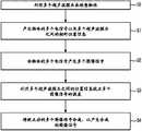
如图3中所示,通过利用多个超声波探头10来检查物体(操作50)。与如图2中所示出的相似,所述多个超声波探头10中的每个均可从不同的角度接触物体,且均可朝着物体的内部照射超声波。As shown in FIG. 3, an object is inspected by using a plurality of ultrasonic probes 10 (operation 50). Similar to that shown in FIG. 2 , each of the plurality of
每个超声波探头10接收从物体的内部组织反射然后返回的超声波信号,然后每个超声波探头10将接收的超声波信号转换成电信号。因此,安装在每个相应的超声波探头10上的相应的传感器15感测在对物体进行测量时多个超声波探头10之间的相对位置,从而产生位置信息(操作51)。Each
例如,在使用两个超声波探头10对物体进行超声波测量的情况下,安装在第二超声波探头10上的第二传感器15可感测第二超声波探头10相对于设置有第一传感器15的第一超声波探头10的位置。具体地,感测的位置信息可包括:第二超声波探头10与第一超声波探头10相隔多远的信息,从而测量第二超声波探头;关于第二超声波探头与第一超声波探头之间的角度的信息,更具体地,感测的位置信息可包括关于第一超声波探头与第二超声波探头之间的距离和/或角度的信息。For example, in the case where two
控制部分20可从相应的超声波探头10接收与物体有关的多个电信号,然后可产生相应的多个图像信号(操作52)。The
当产生所述多个图像信号时,控制部分20利用由安装在超声波探头10上的传感器15感测的关于多个超声波探头10的位置信息来校正与相应的图像信号有关的一个或多个误差(操作53)。由于所述多个图像信号中的每个均为从不同的相对角度和位置测量物体所得到的结果,因此,从多个测量结果中的一个测量结果没有获得的具体图像可从多个测量结果中的不同的另一个测量结果中呈现。因此,为了获得期望的结果,控制部分20利用由传感器15感测的关于多个超声波探头10的位置信息对多个图像信号进行比较。于是,通过对所述信号进行比较,可校正与相应的图像信号有关的误差,同时消除人工假象。When the plurality of image signals are generated, the
控制部分20可将校正后的相应的图像信号合成,以产生合成的图像信号,并可将物体的图像显示在显示部分上(操作54)。通过将校正后的相应的图像信号(该图像信号已经消除了一个或多个人工假象)合成来产生合成的图像信号,从而获得物体的内部组织的更加清晰的图像。The
尽管已经参照附图在上面描述了本公开的示例性实施例,但是应该清楚地理解,这些示例性实施例并非具体限制本公开的范围。因此,本领域技术人员应该理解的是,在不脱离本公开的原理和精神的情况下,可以对这些示例性实施例进行各种替代、更改和/或修改。因此,应该理解的是,本公开的范围不是由上面示出的技术构造和布置的具体实施方式限定,而是由权利要求限定,该范围内的所有差异均将被解释为包括在本公开中。Although the exemplary embodiments of the present disclosure have been described above with reference to the accompanying drawings, it should be clearly understood that these exemplary embodiments do not specifically limit the scope of the present disclosure. Therefore, those skilled in the art should understand that various substitutions, changes and/or modifications can be made to these exemplary embodiments without departing from the principles and spirit of the present disclosure. Therefore, it should be understood that the scope of the present disclosure is not defined by the specific embodiments of the technical configuration and arrangement shown above but by the claims, and all differences within the scope will be construed as being included in the present disclosure. .
Claims (18)
Applications Claiming Priority (2)
| Application Number | Priority Date | Filing Date | Title |
|---|---|---|---|
| KR10-2011-0010427 | 2011-02-07 | ||
| KR1020110010427AKR20120090170A (en) | 2011-02-07 | 2011-02-07 | Ultrasound measuring apparatus and controlling method thereof |
Publications (1)
| Publication Number | Publication Date |
|---|---|
| CN102626324Atrue CN102626324A (en) | 2012-08-08 |
Family
ID=46584841
Family Applications (1)
| Application Number | Title | Priority Date | Filing Date |
|---|---|---|---|
| CN201210026730XAPendingCN102626324A (en) | 2011-02-07 | 2012-02-07 | Ultrasound measuring apparatus and control method thereof |
Country Status (3)
| Country | Link |
|---|---|
| US (1) | US20120203107A1 (en) |
| KR (1) | KR20120090170A (en) |
| CN (1) | CN102626324A (en) |
Cited By (10)
| Publication number | Priority date | Publication date | Assignee | Title |
|---|---|---|---|---|
| CN103750857A (en)* | 2013-12-30 | 2014-04-30 | 深圳市一体医疗科技股份有限公司 | Working angle determining method and system for working equipment |
| CN103759700A (en)* | 2013-12-30 | 2014-04-30 | 深圳市一体医疗科技股份有限公司 | Angle determination method and system for ultrasonic equipment |
| CN105455849A (en)* | 2014-09-12 | 2016-04-06 | 南京星顿医疗科技有限公司 | Mammary gland volume ultrasonic imaging device and method |
| CN105491960A (en)* | 2013-07-02 | 2016-04-13 | 三星电子株式会社 | Ultrasonic diagnostic apparatus and method of operating the same |
| WO2017016239A1 (en)* | 2015-07-28 | 2017-02-02 | 中慧医学成像有限公司 | Three-dimensional imaging ultrasonic scanning method |
| CN106659474A (en)* | 2014-08-28 | 2017-05-10 | 三星电子株式会社 | Ultrasonic diagnostic apparatus for self-diagnosis and remote diagnosis and method of operating ultrasonic diagnostic apparatus |
| US9877699B2 (en) | 2012-03-26 | 2018-01-30 | Teratech Corporation | Tablet ultrasound system |
| CN109640827A (en)* | 2016-03-23 | 2019-04-16 | 皇家飞利浦有限公司 | Method and apparatus for improving the measurement of velocity of blood flow |
| US10667790B2 (en) | 2012-03-26 | 2020-06-02 | Teratech Corporation | Tablet ultrasound system |
| US11123041B2 (en) | 2014-08-28 | 2021-09-21 | Samsung Electronics Co., Ltd. | Ultrasound diagnosis apparatus for self-diagnosis and remote-diagnosis, and method of operating the ultrasound diagnosis apparatus |
Families Citing this family (13)
| Publication number | Priority date | Publication date | Assignee | Title |
|---|---|---|---|---|
| JP6033701B2 (en)* | 2013-02-13 | 2016-11-30 | ジーイー・メディカル・システムズ・グローバル・テクノロジー・カンパニー・エルエルシー | Ultrasonic diagnostic apparatus and control program therefor |
| ITAQ20130003A1 (en)* | 2013-04-23 | 2014-10-24 | Amid S R L | METHOD AND DEVICE FOR THE ASSESSMENT OF THE QUANTITATIVE DYNAMIC FUNCTIONALITY OF THE SKELETAL MUSCLES |
| KR101660369B1 (en)* | 2013-07-26 | 2016-09-27 | 삼성전자주식회사 | Apparatus and method for generating ultrasound image |
| CN103713537B (en)* | 2013-12-31 | 2016-09-21 | 深圳市康丽达实业有限公司 | A kind of Wireless sound control device |
| KR102258800B1 (en)* | 2014-05-15 | 2021-05-31 | 삼성메디슨 주식회사 | Ultrasound diagnosis apparatus and mehtod thereof |
| US10675006B2 (en)* | 2015-05-15 | 2020-06-09 | Siemens Medical Solutions Usa, Inc. | Registration for multi-modality medical imaging fusion with narrow field of view |
| KR101683518B1 (en) | 2015-07-22 | 2016-12-07 | 기아자동차 주식회사 | Contactless durability diagnosis apparatus and method |
| WO2018055504A2 (en)* | 2016-09-20 | 2018-03-29 | Uc-Care Ltd. | Method and system for multi probe real-time scanning |
| CN107091879A (en)* | 2017-06-12 | 2017-08-25 | 武汉展科科技有限公司 | Composite Material Flaw Detector Based on Multiple Ultrasonic Technologies |
| EP3513733A1 (en)* | 2018-01-23 | 2019-07-24 | Koninklijke Philips N.V. | Ultrasound imaging apparatus and method |
| KR102512104B1 (en)* | 2020-05-07 | 2023-03-22 | 한국과학기술연구원 | Apparatus and method for generating 3d ultrasound image |
| KR102465348B1 (en)* | 2020-06-11 | 2022-11-11 | 한국과학기술연구원 | Method for determining relative position between arrays of flexible array device |
| KR102746408B1 (en)* | 2021-10-29 | 2024-12-24 | 한국 한의학 연구원 | Pressure algometer for detaching ultrasonic probe |
Citations (7)
| Publication number | Priority date | Publication date | Assignee | Title |
|---|---|---|---|---|
| US6193665B1 (en)* | 1998-12-31 | 2001-02-27 | General Electric Company | Doppler angle unfolding in ultrasound color flow and Doppler |
| US20060020207A1 (en)* | 2004-07-12 | 2006-01-26 | Siemens Medical Solutions Usa, Inc. | Volume rendering quality adaptations for ultrasound imaging |
| US20060058671A1 (en)* | 2004-08-11 | 2006-03-16 | Insightec-Image Guided Treatment Ltd | Focused ultrasound system with adaptive anatomical aperture shaping |
| CN101002681A (en)* | 2006-01-19 | 2007-07-25 | 株式会社东芝 | Ultrasonic probe track display device and method, ultrasonic wave diagnosis device and method |
| JP2008307087A (en)* | 2007-06-12 | 2008-12-25 | Toshiba Corp | Ultrasonic diagnostic equipment |
| EP2113202A1 (en)* | 2008-05-02 | 2009-11-04 | Canon Kabushiki Kaisha | Ultrasonic measurement apparatus |
| CN101612048A (en)* | 2008-06-27 | 2009-12-30 | 西门子公司 | Ultrasonic probe and ultrasonic scanning device |
Family Cites Families (1)
| Publication number | Priority date | Publication date | Assignee | Title |
|---|---|---|---|---|
| US20110125022A1 (en)* | 2009-11-25 | 2011-05-26 | Siemens Medical Solutions Usa, Inc. | Synchronization for multi-directional ultrasound scanning |
- 2011
- 2011-02-07KRKR1020110010427Apatent/KR20120090170A/ennot_activeCeased
- 2012
- 2012-02-06USUS13/366,620patent/US20120203107A1/ennot_activeAbandoned
- 2012-02-07CNCN201210026730XApatent/CN102626324A/enactivePending
Patent Citations (7)
| Publication number | Priority date | Publication date | Assignee | Title |
|---|---|---|---|---|
| US6193665B1 (en)* | 1998-12-31 | 2001-02-27 | General Electric Company | Doppler angle unfolding in ultrasound color flow and Doppler |
| US20060020207A1 (en)* | 2004-07-12 | 2006-01-26 | Siemens Medical Solutions Usa, Inc. | Volume rendering quality adaptations for ultrasound imaging |
| US20060058671A1 (en)* | 2004-08-11 | 2006-03-16 | Insightec-Image Guided Treatment Ltd | Focused ultrasound system with adaptive anatomical aperture shaping |
| CN101002681A (en)* | 2006-01-19 | 2007-07-25 | 株式会社东芝 | Ultrasonic probe track display device and method, ultrasonic wave diagnosis device and method |
| JP2008307087A (en)* | 2007-06-12 | 2008-12-25 | Toshiba Corp | Ultrasonic diagnostic equipment |
| EP2113202A1 (en)* | 2008-05-02 | 2009-11-04 | Canon Kabushiki Kaisha | Ultrasonic measurement apparatus |
| CN101612048A (en)* | 2008-06-27 | 2009-12-30 | 西门子公司 | Ultrasonic probe and ultrasonic scanning device |
Cited By (19)
| Publication number | Priority date | Publication date | Assignee | Title |
|---|---|---|---|---|
| US9877699B2 (en) | 2012-03-26 | 2018-01-30 | Teratech Corporation | Tablet ultrasound system |
| US12115023B2 (en) | 2012-03-26 | 2024-10-15 | Teratech Corporation | Tablet ultrasound system |
| US12102480B2 (en) | 2012-03-26 | 2024-10-01 | Teratech Corporation | Tablet ultrasound system |
| US11857363B2 (en) | 2012-03-26 | 2024-01-02 | Teratech Corporation | Tablet ultrasound system |
| US11179138B2 (en) | 2012-03-26 | 2021-11-23 | Teratech Corporation | Tablet ultrasound system |
| US10667790B2 (en) | 2012-03-26 | 2020-06-02 | Teratech Corporation | Tablet ultrasound system |
| CN105491960B (en)* | 2013-07-02 | 2019-02-22 | 三星电子株式会社 | Ultrasonic diagnostic apparatus and method of operating the same |
| US10201326B2 (en) | 2013-07-02 | 2019-02-12 | Samsung Electronics Co., Ltd. | Ultrasonic diagnostic apparatus and method of operating the same |
| CN105491960A (en)* | 2013-07-02 | 2016-04-13 | 三星电子株式会社 | Ultrasonic diagnostic apparatus and method of operating the same |
| CN103750857A (en)* | 2013-12-30 | 2014-04-30 | 深圳市一体医疗科技股份有限公司 | Working angle determining method and system for working equipment |
| CN103759700A (en)* | 2013-12-30 | 2014-04-30 | 深圳市一体医疗科技股份有限公司 | Angle determination method and system for ultrasonic equipment |
| US10660607B2 (en) | 2014-08-28 | 2020-05-26 | Samsung Electronics Co., Ltd. | Ultrasound diagnosis apparatus for self-diagnosis and remote-diagnosis, and method of operating the ultrasound diagnosis apparatus |
| CN106659474A (en)* | 2014-08-28 | 2017-05-10 | 三星电子株式会社 | Ultrasonic diagnostic apparatus for self-diagnosis and remote diagnosis and method of operating ultrasonic diagnostic apparatus |
| US11123041B2 (en) | 2014-08-28 | 2021-09-21 | Samsung Electronics Co., Ltd. | Ultrasound diagnosis apparatus for self-diagnosis and remote-diagnosis, and method of operating the ultrasound diagnosis apparatus |
| CN105455849A (en)* | 2014-09-12 | 2016-04-06 | 南京星顿医疗科技有限公司 | Mammary gland volume ultrasonic imaging device and method |
| AU2016299005B2 (en)* | 2015-07-28 | 2019-05-09 | Telefield Medical Imaging Limited | Three-dimensional imaging ultrasonic scanning method |
| WO2017016239A1 (en)* | 2015-07-28 | 2017-02-02 | 中慧医学成像有限公司 | Three-dimensional imaging ultrasonic scanning method |
| CN109640827A (en)* | 2016-03-23 | 2019-04-16 | 皇家飞利浦有限公司 | Method and apparatus for improving the measurement of velocity of blood flow |
| CN109640827B (en)* | 2016-03-23 | 2022-04-29 | 皇家飞利浦有限公司 | Method and apparatus for improving the measurement of blood flow rate |
Also Published As
| Publication number | Publication date |
|---|---|
| KR20120090170A (en) | 2012-08-17 |
| US20120203107A1 (en) | 2012-08-09 |
Similar Documents
| Publication | Publication Date | Title |
|---|---|---|
| CN102626324A (en) | Ultrasound measuring apparatus and control method thereof | |
| JP5294687B2 (en) | Ultrasonic measuring device and control method thereof | |
| JP5588924B2 (en) | Ultrasonic diagnostic equipment | |
| US9700282B2 (en) | Ultrasound system and method of detecting pressure applied to object | |
| JP6718520B2 (en) | Ultrasonic diagnostic apparatus and method for controlling ultrasonic diagnostic apparatus | |
| JP2007202829A (en) | Ultrasonic diagnostic system | |
| CN101612048A (en) | Ultrasonic probe and ultrasonic scanning device | |
| JP2015066219A5 (en) | ||
| JP2014050589A (en) | Measuring apparatus | |
| JP2011031023A (en) | Ultrasonic system and method for setting sagittal view | |
| US11324487B2 (en) | Ultrasound diagnostic apparatus and control method of ultrasound diagnostic apparatus | |
| JP6386853B2 (en) | Ultrasonic diagnostic equipment | |
| CN116671964A (en) | Pressure correction method for elastic detection probe, elastic detection probe and system | |
| US20240008754A1 (en) | An apparatus and a method for measuring jugular vein pressure waveform | |
| JP5697716B2 (en) | Ultrasonic measuring device | |
| JP2008000214A (en) | Ultrasonic diagnostic equipment and method for displaying ultrasonic diagnostic image | |
| JP2017018510A (en) | Ultrasonic diagnostic equipment and image forming method thereof | |
| WO2023171272A1 (en) | Ultrasonic diagnostic device, control method for ultrasonic diagnostic device, and distance measurement device | |
| JP2013244354A (en) | Ultrasonic image processor, ultrasonic image processing program, and ultrasonic image processing method | |
| US20250275754A1 (en) | Ultrasound diagnostic apparatus and method of controlling ultrasound diagnostic apparatus | |
| JP2004261245A (en) | Ultrasonograph | |
| JP2008020328A (en) | Ultrasonic inspection equipment | |
| JP2024162387A (en) | ULTRASONIC DIAGNOSTIC APPARATUS, INFORMATION PROCESSING APPARATUS, ULTRASONIC DIAGNOSTIC SYSTEM, AND ULTRASONIC DIAGNOSTIC METHOD | |
| JP6389116B2 (en) | Ultrasonic image display device and control program thereof | |
| JP2023140926A (en) | Ultrasound diagnostic apparatus and control method of ultrasound diagnostic apparatus |
Legal Events
| Date | Code | Title | Description |
|---|---|---|---|
| C06 | Publication | ||
| PB01 | Publication | ||
| SE01 | Entry into force of request for substantive examination | ||
| SE01 | Entry into force of request for substantive examination | ||
| C02 | Deemed withdrawal of patent application after publication (patent law 2001) | ||
| WD01 | Invention patent application deemed withdrawn after publication | Application publication date:20120808 |