CN102625766A - Systems and methods for recovering and controlling post-recovery movement of an unmanned aerial vehicle - Google Patents
Systems and methods for recovering and controlling post-recovery movement of an unmanned aerial vehicleDownload PDFInfo
- Publication number
- CN102625766A CN102625766ACN2010800285307ACN201080028530ACN102625766ACN 102625766 ACN102625766 ACN 102625766ACN 2010800285307 ACN2010800285307 ACN 2010800285307ACN 201080028530 ACN201080028530 ACN 201080028530ACN 102625766 ACN102625766 ACN 102625766A
- Authority
- CN
- China
- Prior art keywords
- aircraft
- recovery system
- capturing
- elastic rod
- capture
- Prior art date
- Legal status (The legal status is an assumption and is not a legal conclusion. Google has not performed a legal analysis and makes no representation as to the accuracy of the status listed.)
- Pending
Links
- 238000011084recoveryMethods0.000titleclaimsabstractdescription63
- 238000000034methodMethods0.000titleclaimsabstractdescription24
- 239000000463materialSubstances0.000claimsdescription21
- OKTJSMMVPCPJKN-UHFFFAOYSA-NCarbonChemical compound[C]OKTJSMMVPCPJKN-UHFFFAOYSA-N0.000claimsdescription9
- 238000003306harvestingMethods0.000claimsdescription9
- 229910052799carbonInorganic materials0.000claimsdescription5
- 229920000049Carbon (fiber)Polymers0.000claimsdescription3
- 239000004917carbon fiberSubstances0.000claimsdescription3
- 239000002131composite materialSubstances0.000claimsdescription3
- 229910002804graphiteInorganic materials0.000claimsdescription3
- 239000010439graphiteSubstances0.000claimsdescription3
- 239000007770graphite materialSubstances0.000claimsdescription3
- VNWKTOKETHGBQD-UHFFFAOYSA-NmethaneChemical compoundCVNWKTOKETHGBQD-UHFFFAOYSA-N0.000claimsdescription3
- 235000017166Bambusa arundinaceaNutrition0.000claimsdescription2
- 235000017491Bambusa tuldaNutrition0.000claimsdescription2
- 241001330002BambuseaeSpecies0.000claimsdescription2
- 235000015334Phyllostachys viridisNutrition0.000claimsdescription2
- 239000011425bambooSubstances0.000claimsdescription2
- 239000003365glass fiberSubstances0.000claimsdescription2
- 238000010586diagramMethods0.000description7
- 239000011248coating agentSubstances0.000description4
- 238000000576coating methodMethods0.000description4
- 241000251468ActinopterygiiSpecies0.000description1
- ZOXJGFHDIHLPTG-UHFFFAOYSA-NBoronChemical class[B]ZOXJGFHDIHLPTG-UHFFFAOYSA-N0.000description1
- 229910052796boronInorganic materials0.000description1
- 238000013016dampingMethods0.000description1
- 230000007613environmental effectEffects0.000description1
- 230000005484gravityEffects0.000description1
- 230000014759maintenance of locationEffects0.000description1
- 238000012544monitoring processMethods0.000description1
- 238000004064recyclingMethods0.000description1
Images


Classifications
- B—PERFORMING OPERATIONS; TRANSPORTING
- B64—AIRCRAFT; AVIATION; COSMONAUTICS
- B64C—AEROPLANES; HELICOPTERS
- B64C39/00—Aircraft not otherwise provided for
- B64C39/02—Aircraft not otherwise provided for characterised by special use
- B64C39/024—Aircraft not otherwise provided for characterised by special use of the remote controlled vehicle type, i.e. RPV
- B—PERFORMING OPERATIONS; TRANSPORTING
- B64—AIRCRAFT; AVIATION; COSMONAUTICS
- B64F—GROUND OR AIRCRAFT-CARRIER-DECK INSTALLATIONS SPECIALLY ADAPTED FOR USE IN CONNECTION WITH AIRCRAFT; DESIGNING, MANUFACTURING, ASSEMBLING, CLEANING, MAINTAINING OR REPAIRING AIRCRAFT, NOT OTHERWISE PROVIDED FOR; HANDLING, TRANSPORTING, TESTING OR INSPECTING AIRCRAFT COMPONENTS, NOT OTHERWISE PROVIDED FOR
- B64F1/00—Ground or aircraft-carrier-deck installations
- B64F1/02—Ground or aircraft-carrier-deck installations for arresting aircraft, e.g. nets or cables
- B64F1/0297—Ground or aircraft-carrier-deck installations for arresting aircraft, e.g. nets or cables adjustable to align with aircraft trajectory
- B—PERFORMING OPERATIONS; TRANSPORTING
- B64—AIRCRAFT; AVIATION; COSMONAUTICS
- B64U—UNMANNED AERIAL VEHICLES [UAV]; EQUIPMENT THEREFOR
- B64U70/00—Launching, take-off or landing arrangements
- B64U70/30—Launching, take-off or landing arrangements for capturing UAVs in flight by ground or sea-based arresting gear, e.g. by a cable or a net
Landscapes
- Engineering & Computer Science (AREA)
- Aviation & Aerospace Engineering (AREA)
- Mechanical Engineering (AREA)
- Remote Sensing (AREA)
- Tires In General (AREA)
- Toys (AREA)
- Control Of Position, Course, Altitude, Or Attitude Of Moving Bodies (AREA)
- Catching Or Destruction (AREA)
- Manipulator (AREA)
- Transmission Devices (AREA)
Abstract
Description
Translated fromChinese对相关申请的交叉引用Cross References to Related Applications
此申请要求2009年4月24日递交的美国临时申请号61/172,663的优先权,其以参考方式被合并于此。This application claims priority to US Provisional Application No. 61/172,663, filed April 24, 2009, which is hereby incorporated by reference.
技术领域technical field
本公开大体上涉及用于回收无人航空器以及控制航空器的回收后运动的系统和方法。The present disclosure generally relates to systems and methods for recovering unmanned aerial vehicles and controlling post-recovery movement of the aircraft.
背景技术Background technique
无人航空器或飞行器(UAVs)在载人飞行操作昂贵和/或危险而难以接受的领域,提供增强和经济性的门路(access)。例如,配备有遥控操作的可移动照相机的无人航空器可以执行各式各样的监视任务,包括在渔业上探测鱼群,监视天气条件,给国家政府提供边境巡逻,以及在军事行动之前,期间,和/或之后提供军事监视。Unmanned aerial vehicles or aerial vehicles (UAVs) provide enhanced and economical access in areas where manned flight operations are prohibitively expensive and/or dangerous. For example, unmanned aerial vehicles equipped with remotely operated mobile cameras can perform a variety of surveillance tasks, including detecting fish stocks on fisheries, monitoring weather conditions, providing border patrols for national governments, and prior to and during military operations , and/or provide military surveillance thereafter.
然而,许多无人航空器系统(其可以包括该航空器本身以及发射装置和回收装置)难以被安装和操作于狭窄的区域,例如小渔船,登陆载体,或其它运输器的甲板。相应地,当空间不足以运作常规着陆时,这种航空器系统的操作通常包括用弹性的回收绳收回或捕获该航空器。尽管此技术已经在许多情形下证明是成功的,对于提高回收航空器的系统效率的还是存在持续的需求。However, many unmanned aircraft systems (which may include the aircraft itself as well as launch and recovery devices) are difficult to install and operate in confined areas, such as the decks of small fishing boats, landing vehicles, or other vehicles. Accordingly, when there is insufficient space to operate a conventional landing, the operation of such aircraft systems typically includes retrieving or capturing the aircraft with elastic recovery lines. Although this technique has proven successful in many situations, there is a continuing need to improve the efficiency of systems for recovering aircraft.
附图说明Description of drawings
图1是根据此公开的实施方式的系统部分示意图,该系统被设置为回收飞行中的无人航空器和控制该航空器的回收后运动。FIG. 1 is a partial schematic diagram of a system configured to recover an unmanned aerial vehicle in flight and control the post-recovery motion of the aircraft in accordance with an embodiment of the disclosure.
图2A-2F是根据此公开的实施方式的用于回收飞行中的无人航空器和控制该航空器的回收后运动的系统和方法的部分示意图。2A-2F are partial schematic illustrations of systems and methods for recovering an unmanned aerial vehicle in flight and controlling post-recovery motion of the aircraft according to embodiments of the disclosure.
图3A-3F是根据此公开的另一实施方式的用于回收飞行中的无人航空器和控制该航空器的回收后运动的系统和方法的部分示意图。3A-3F are partial schematic illustrations of systems and methods for recovering an unmanned aerial vehicle in flight and controlling post-recovery motion of the aircraft according to another embodiment of the disclosure.
图4A-4D是根据此公开的又一实施方式的用于回收飞行中的无人航空器和控制该航空器的回收后运动的系统和方法的部分示意图。4A-4D are partial schematic illustrations of systems and methods for recovering an unmanned aerial vehicle in flight and controlling post-recovery motion of the aircraft according to yet another embodiment of the disclosure.
图5A是根据此公开的另一实施方式配置的航空器俘获构件的远侧部分的部分示意图。5A is a partial schematic view of a distal portion of an aircraft capture member configured in accordance with another embodiment of the present disclosure.
图5B是根据此公开的实施方式配置的航空器俘获构件的又一实施方式的部分示意图。Figure 5B is a partial schematic illustration of yet another embodiment of an aircraft capture member configured in accordance with embodiments of the disclosure.
图5C是根据此公开的又一实施方式配置的航空器回收系统的部分示意图。5C is a partial schematic diagram of an aircraft recovery system configured in accordance with yet another embodiment of the disclosure.
详细说明Detailed description
本公开描述了用于回收无人航空器和控制该航空器的回收后运动的系统和方法。本公开的某些实施方式的许多细节被阐述于下文以及图1-5C中,以提供对这些实施方式的彻底理解。众所周知的结构,系统,以及通常与这种系统有关的方法未作详细描述,以免不必要地遮蔽对此公开的各种实施方式的描述。另外,本领域技术人员将理解,其它的实施方式可以在不具有如下所述的部分细节情况下被实施。The present disclosure describes systems and methods for recovering an unmanned aerial vehicle and controlling the post-recovery movement of the aircraft. Numerous details of certain embodiments of the present disclosure are set forth below and in Figures 1-5C to provide a thorough understanding of these embodiments. Well-known structures, systems, and methods generally associated with such systems have not been described in detail so as not to unnecessarily obscure the description of the various embodiments of this disclosure. Additionally, those skilled in the art will understand that other embodiments may be practiced without some of the details described below.
A.用于回收无人航空器和控制无人航空器的回收后运动的系统和方法的实施A. Implementation of Systems and Methods for Recovering Unmanned Aircraft and Controlling Post-Recovery Movement of Unmanned Aircraft方式Way
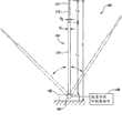
图1是根据此公开的实施方式的航空器回收系统100的部分示意图,其被设置为拦截和回收飞行中的无人航空器(未示出),并控制该航空器的回收后运动。该航空器回收系统100可以包括,例如,基底部分102(如图概示)和细长的弹性杆或航空器俘获构件104,其附着于该基底部分102。在该示意的实施方式中,该弹性杆104具有第一端,其通过附着构件或接头106可移动地连接至该基底部分102,以及第二自由端,其被设置为拦截该航空器。该接头106被设置为,容许该弹性杆104相对于该基底部分102在拦截飞行中的该无人航空器之前,期间,以及之后绕轴旋转(如虚线所示)。当航空器撞击该航空器回收系统100时,该弹性杆104可释放地俘获该航空器,并且该系统100被设置为吸收和耗散该航空器的着陆力并回收该航空器。一旦被俘获,该航空器可以由其一个机翼或该航空器的另一适合的组件,或者由该航空器承载的俘获线悬挂在该弹性杆104上。以下参照图2A-5C描述关于该航空器回收系统100以及该系统100用于回收和控制航空器的回收后运动的更多细节。1 is a partial schematic diagram of an
该基底部分102可以包括各式各样的不同结构(例如,大体上为刚性,半刚性和/或可膨胀的),其被设置为在俘获和回收作业期间支持该弹性杆104。一般而言,该基底部分102被设置为(a)在俘获操作以前将该弹性杆104保持在期望的位置(例如,相对于地面呈斜面或呈一角度并朝向该航空器),和(b)在俘获和回收期间支持该弹性杆104,以及帮助防止该航空器和其组件用过度的力撞击地面或周围结构。该基底部分102被设置为搁置于地面或适合的支持平台上(例如,卡车或者其它适合的登陆载体,船或其它水上工具,建筑,或其它适合的载体和/或结构)。在其它实施方式中,该基底部分102可以具有不同的布置和/或可以由不同的材料组成。此外,一些实施方式可以不包括该基底部分102。在这类情形下,该弹性杆104可以用其它适合的支持组件进行支持和/或可以使自身支持组件。The
该弹性杆104可以包括第一部分110和位于该第一部分110的远端的第二部分112。该第一和第二部分110和112互相对准(至少初始地在俘获和回收操作之前)并沿该弹性杆104的纵向轴延伸。在该示意的实施方式中,该第一和第二部分110和112一体成形(integral with each other)。然而在其它实施方式中,该第一和第二部分110和112可以是分离的组件,它们被固定地或可释放地连接或接合在一起。在一个实施方式中,例如,该弹性杆104的个别的部分可以通过弹性的线或索(例如松紧绳)连接在一起。此外,该弹性杆104的个别部分可以具有相互之间伸缩式或折叠式的布置。在其它实施方式中,该弹性杆104可以不包括分离的部分,或该弹性杆104可以包括三个以上三个以上离散的部分。The
根据所期望的操作要求,该第一部分110和该第二部分112可以具有各种不同的尺寸和结构。在该示意的实施方式中,例如,该第一部分110具有第一截面尺寸D1和第一长度L1,并且该第二部分112具有第二截面尺寸D2和第二长度L2,它们分别小于该第一截面尺寸D1和该第一长度L1。然而,在其它实施方式中,该第一和第二部分110和112可以具有相互之间不同布置。例如,该第一和第二部分110和112可以具有相同的截面尺寸和/或该第二部分112可以具有和该第一部分110不同的长度。The
在此实施方式的另一方面,该弹性杆104的远侧部分可以被设置以高出局部表面(例如,图1所示的地面)高度E。该高度E可以基于该弹性杆104的结构,该航空器(未示出)的结构,以及局部环境而变化。该系统100的一个特征是该高度E只需要和预期的俘获高度一样高。因此,该弹性杆104的全长可以比许多现有的需要高得多的高度部署的航空器俘获装置显著减少。此特征的一个优点是该弹性杆104可以比现有的较大的航空器俘获系统易于存储和/或运输。此外,在俘获后,该航空器可以更易于回收,因为俘获高度被降低。In another aspect of this embodiment, the distal portion of the
该弹性杆104可以由碳纤维材料,碳石墨材料,玻璃纤维,其它复合材料(例如碳/石墨或石墨/硼复合材料),竹材,或另外具有期望的材料特性的适合的材料组成。被选择的材料,例如,应该具有在航空器飞入该弹性杆104时拦截该航空器,并且一旦俘获后,能够通过航空器的一个机翼或该航空器承载的另外的适合的俘获机制悬挂起该航空器的强度和弹性。在此实施方式的一个特定方面,该第一部分110具有第一刚性,并且该第二部分112具有小于该第一刚性的第二刚性。该第二部分112相应地比该第一部分110更为弹性,并被设置为在操作期间比该第一部分110弯曲或伸曲(flex)得更多。关于此特征的更多细节参照图2A-2F被描述如下。然而,在其它实施方式中,该第一和第二部分110和112可以具有相同或者近似相同的刚性。在其它实施方式中,该第一和/或第二部分110和112可以由一种或多种具有不同性质和/或特性的不同于如上所述的材料组成。The
在若干实施方式中,该弹性杆104的第二部分112的至少部分可以被相对软的绳状材料113或其它适合的材料覆盖或包覆,这些材料被设置为向该航空器承载的钩子部分提供增强的固定力。该材料,例如,可以在该第二部分112的期望部分或直接涂覆在该弹性杆104的第二部分112上的外涂层之上的相对软和弹性的鞘。该鞘或外涂层预期可减少和/或抑制俘获期间该航空器的钩子部分的滑动,并且也预期可加强该第二部分112并使该弹性杆104在沿该弹性杆104的纵向轴承受拉力使更具弹性。在其它实施方式中,该弹性杆104的一个或多个另外的部分(例如,该第一部分110的至少部分)可以包括该鞘或涂层。在其它实施方式中,该第一和/或第二部分110和112可以包括一个或多个棱或突起,其被设置为防止或抑制钩子从该航空器滑动脱该弹性杆104。然而,该鞘/涂层/棱,是任选的特征,其可以不被包括于一些实施方式中。In several embodiments, at least a portion of the
该能量获取和耗散组件108可以包括液压阻尼器,气压阻尼器,(多种)塑性变形材料,被动式收片盘,制动器,或其它适合的被设置为耗散该航空器的动能的阻尼装置。该能量获取和耗散组件108的一个特征是,该组件可预期地提供与该航空器的俘获和回收有关的力的精确控制。相应地,在该俘获和回收过程的全程中可以紧密地控制回收和能源管理。此特征可预期地可以帮助抑制和/或防止在俘获操作期间对该航空器的损害。在其它实施方式中,该能量获取和耗散组件可以具有不同的结构和/或包括不同的特征。在其它实施方式中,该系统100不包括该能量获取和耗散组件108。The energy harvesting and
在操作中,该系统100可以被展开至预定位置并被配置为用于俘获和回收操作的主要装置。例如,该系统100,可以为模块化的系统,并且操作者可以总体上拆散或部分组装的状态运输该系统的元件至着陆区域,并当场组装这些组件。然而,在另一个实施方式中,该系统100可以总体上组合的结构被运输至期望的着陆区域。In operation, the
该航空器回收系统100是可调整尺寸(scalable)的系统,其能作为主要的航空器回收系统被用于各种不同的航空器结构和/或布置。例如,如上所述,该弹性杆104的全长和截面尺寸可以至少部分地基于要被回收的航空器的尺寸,该航空器的操作条件,和/或该系统100的操作考虑事项(例如,该系统100的位置,期望的该系统100的可运输性,等等)。The
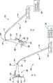
图2A-2F是根据此公开的实施方式的系统100的部分示意图,其回收飞行中的无人航空器200,并控制该航空器200的回收后运动。例如,图2A和2B分别是该航空器200在俘获之前接近该系统100的俯视图和侧视图。该航空器200可以包括机身201,从该机身201向外延伸的一对机翼或升力面202,以及被设置在该机身201的尾部以在飞行时推动该航空器200的推进器204。该个别的机翼202包括前缘210,后缘212,和外侧缘214。每一个机翼202还可以在该外侧缘214处包括向上延伸的用于横向稳定和控制的小翼203。该航空器200在每一个机翼202的外侧缘214处进一步包括接合或俘获装置216。在其它实施方式中,该接合装置216可以具有不同的结构和/或可以被设置在该航空器200的另一适合的位置。另外,该航空器200可以包括不同数目的接合装置216。2A-2F are partial schematic diagrams of a
在此实施方式中,该弹性杆104为朝向该航空器200的呈一角度或斜面。此布置的一个优点是,它可以在俘获该航空器200后为该弹性杆104提供更大的移动范围。然而,在其它实施方式中,该弹性杆104可以相对于该航空器的局部飞行路线和该局部表面(例如,图2B所示的地面)具有大体上垂直的布置或另外布置。In this embodiment, the
接下来参照图2C,该航空器200拦截该弹性杆104的自由端,并且该弹性杆104的第二部分112和机翼202的前缘210相对于彼此朝向相应的接合装置216滑动。现在参照图2D,位于该机翼202的外侧缘214的该接合装置216容纳并保持一部分该弹性杆104的第二部分112,因此导致该航空器200开始偏转或朝向该弹性杆104旋转。和该航空器200碰撞的力还导致该弹性杆104相对于该基底部分102绕轴旋转或移动。例如,在图2D中,该弹性杆104已经从其初始的角形或斜面布置移动至大致垂直位置。此外,该弹性杆104的第二部分112已经响应于该航空器的动量开始伸曲或弯曲。还应当理解,该弹性杆104的第一部分110也可以在俘获操作期间伸曲或弯曲。此外,在一些实施方式中,该基底102也可以被设置为以预定方式移动或咬合,以帮助吸收碰撞的能量。Referring next to FIG. 2C , the
现参照图2E,该回收过程继续,该弹性杆104继续响应该航空器的动量相对于该基底部分102绕轴旋转或移动。在图2E中,例如,该弹性杆104已经移过了该大致垂直的布置,并且目前呈远离该航空器进入的飞行路线的角形或斜面。该第二部分112继续响应来自该航空器200的着陆力伸曲或弯曲。在该航空器200迅速减速时,力从该航空器200被转移至该弹性杆104,并且随后转移至该能量获取和耗散组件108。通过这种方式,该系统100可以吸收大量的该航空器的着陆力。此外,因为在俘获操作期间该航空器200上的应力在碰撞期间主要被施加于该机翼结构上,位于该航空器200的鼻部的精密组件(例如回转台(turret),皮托管(pitot tubes),等等),以及该航空器200的其它易碎部分在俘获和回收操作期间经受很少或没有受应力。Referring now to FIG. 2E , the recovery process continues with the
参照图2F,该航空器200已经达到完全或接近完全停止,并保持为固定至该弹性杆104。如先前所述,该组件108被设置为提供与俘获和回收该航空器200有关的力的精确控制,并帮助抑制,减少,和/或消除在俘获操作期间对该航空器200的损害。在该示意的实施方式中,例如,该航空器200在俘获后被悬在地面以上,并远离其它外部构造,且可以由地面人员(未示出)快速和容易地从该弹性杆104收回。Referring to FIG. 2F , the
如上所述参照图1-2F的该系统100和方法的实施方式的一个特征是,该系统100可以在各种不同的环境和操作条件下被快速展开并配置,用于着陆操作。许多常规的回收系统,例如,需要精细和复杂的组件,它们相对较为固定,并需要大量时间和费用来展开。与这种常规的系统相比,该系统100是模块化的系统,其可以部分组合或拆散状态被容易地输送至各式各样的不同操作环境,并用极少的人力迅速组合并展开,用于着陆操作。另外,因为该系统100具有比许多常规的系统小得多的占地面积,该系统100可被用于许多常规的系统可能不可实施的各式各样的不同操作环境和条件。此外,该航空器200可以在着陆操作后从该系统100迅速回收,以备存储和/或另一任务。A feature of the embodiments of the
如上所述的该系统100的实施方式的另一特征是,它们可被用于回收除了如上参照图2A-2F所述的航空器200之外的各种不同结构的航空器。此特征的一个优点是该系统100能和现有的无人航空器群一起使用,无需对这种航空器进行昂贵的和/或耗时的改变。此外,因为该系统100能和各种不同的航空器一起使用,可以部署单一的系统100,并将其在特定面积或区域中用于不同的无人航空器的全部机群的着陆操作。Another feature of the embodiments of the
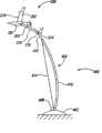
图3A-3G是根据此公开的另一实施方式的系统100的部分示意图,其回收飞行中的无人航空器300并控制该航空器300的回收后运动。例如,图3A和3B分别是该航空器300在俘获以前接近该系统100的俯视图和侧视图。如下参照图3A-3G所述的方法不同于如上所述的技术,因为该航空器300具有和该航空器200不同的结构。具体而言,不是如上参照图2A-2D所述用该航空器的机翼拦截该弹性杆104,该航空器300包括一俘获组件320,其被设置为接合或固定于一部分该弹性杆104,并俘获该航空器300。3A-3G are partial schematic diagrams of a
该俘获组件320可以包括,例如,一个或多个可展开的弹性支持线322(例如,绳或索),其附着于每一个机翼202并被设置为接合该弹性杆104的自由端。在该示意的实施方式中,该支持线322至少贴近穿过该航空器300的重心(center of gravity,CG)的横轴线被连接至每一个机翼202的顶部。如以下以更具体的细节所述,沿着通过该航空器300的CG的横轴线连接该支持线322可以使该航空器300在回收期间上仰,并且在这种操作期间可以帮助提供额外的减速。该俘获组件320还可以包括由该弹性杆104所承载,并被设置为可释放地接合该支持线322的接合特征324(例如,钩子,等等)。在其它实施方式中,该接合特征324可以包括不同的特征和/或具有不同的布置。在至少一些实施方式中,该支持线322还可以包括重量或其它空气动力学特征(未示出),以在飞行中帮助该支持线322保持相对于该航空器300和该接合特征324的适当形状和位置。The
该俘获组件320的一个特征是,该支持线322在该机翼202的自然承力点被连接至每一个机翼202。这种点已经被设计为经得起较大负载,并且相应地,预期可不需要额外的机翼和/或机身支持结构来经受与俘获和回收该航空器300有关的力。此外,该航空器的控制面及该航空器300的其它易碎部分在俘获操作期间经受很少应力或不受应力。A feature of the
接着参照图3C,该支持线322拦截并接合该弹性杆104的第二部分112。该接合特征324容纳并保持部分该支持线322,由此将该航空器300固定至该弹性杆104。现参照图3D,该航空器在俘获后300开始上仰并减速,从而将该弹性杆104从其初始的角形或斜面布置移动至大致垂直位置。如上所述,该支持线322至少在靠近通过该航空器300的CG的横轴线处被锚定。相应地,在该弹性杆104俘获该支持线322后,该航空器300的动量使该航空器300上仰至大致鼻高姿势并保持深度减速。此特征的一个优点是,其容许该支持线322在初始产生该航空器300的向上动量时迅速在该航空器300上引起空气动力减速力,预计此特征有助于迅速减速该航空器300,并减少或最小化该航空器300在俘获操作期间接触地面或其它外部构造的可能性。Referring next to FIG. 3C , the
现参照图3E,该回收过程继续,该弹性杆104继续响应该航空器的动量相对于该基底部分102绕轴旋转或移动。例如,该弹性杆104目前呈远离该航空器的飞入路线的角形或斜面。该第二部分112继续响应来自该航空器300的着陆力伸曲或弯曲。在该航空器200迅速减速时,来自该航空器300的力被转移至该弹性杆104和该能量获取和耗散组件108。参照图3F,该航空器300达到完全或接近完全停止,并保持通过该支持线322固定至该弹性杆104。可以选择该支持线322的长度,以使得该航空器300在俘获后保持悬浮在地面或其它外部构造以上,不与之接触。Referring now to FIG. 3E , the recovery process continues with the
图4A-4D是根据此公开的又一实施方式的系统400的部分示意图,其被设置为回收飞行中的无人航空器(例如,以上讨论的航空器200或航空器300)并控制该航空器的回收后运动。该航空器回收系统400可以包括大致类似于如上参照图1所述的系统100的若干特征。该系统400可以包括,例如,基底部分402和连接该基底部分402的细长的弹性杆或航空器俘获构件404。该弹性杆404可以包括第一部分410和位于该第一部分410远端的第二部分412。在该示意的实施方式中,该第二部分412是连接该第一部分410一端的细长线。然而,在其它实施方式中,该第一部分410和/或第二部分412可以由不同的(多种)材料组成和/或具有不同的布置。例如,在一些实施方式中,该弹性杆404不能包括分离的部分,或者该弹性杆404可以包括三个或三个以上离散的部分。4A-4D are partial schematic diagrams of a
该第一和第二部分410和412中至少一个被操作式连接至张力线或收卷线414(如下参照图4所示)。在该示意的实施方式中,例如,该张力线414被连接至该弹性杆404的第二部分412。该系统400还包括张力卷筒408,其被操作式连接至该张力线414,并被设置为在操作期间卷绕/松开该张力线414。在该示意的实施方式中,该张力卷筒408由该基底部分402所承载,并被设置为卷绕/松开该张力线414。然而,在其它实施方式中,该张力卷筒408可以具有相对于该系统400中的另一个组件不同的布置,和/或可以包括不同的特征。例如,该张力卷筒408可以被设置在相对于该基底部分402和/或该弹性杆404的各种不同的位置。At least one of the first and
接着参照图4B,该航空器200拦截该弹性杆404,并且该弹性杆404的第二部分412和该机翼202之一的前缘210相对于彼此朝向该相应的接合装置216滑动。在位于该机翼202的外侧缘214的该接合装置216容纳和保持一部分该第二部分412之后,该航空器200开始围绕该弹性杆404偏转或旋转。与该航空器200的碰撞力还导致整个弹性杆404(该第一和第二部分410和412)弯曲或弯折。在该弹性杆404弯曲时,该张力线414的任何松弛均被该张力卷筒408收起。保持该张力线414相对拉紧可以帮助保持该弹性杆404为弯曲或弯折结构,并帮助转移来自该航空器200的动量和俘获力至该系统400。在其它实施方式中,该第二部分412至少可以响应该航空器200的动量部分伸展。例如,在一个实施方式中,该第二部分412可以在该航空器200碰撞后相对于该第一部分410延伸或卷出一选定距离。Referring next to FIG. 4B , the
现参照图4C,在该航空器200继续以该弹性杆404为轴偏转或旋转时,该弹性杆404已经由其初始的大致垂直布置移动至角形或斜面布置。此外,该弹性杆404继续响应来自该航空器200的力伸曲或弯曲。参照图4D,该航空器200已经达到完全或近似完全停止,并保持固定至该弹性杆404。该张力线414保持大致拉紧,其可以在俘获后帮助保持该航空器200悬在地面以上并远离其它外部构造。在此布置中,该航空器200可以由地面人员(未示出)快速和易于从该弹性杆404收回。Referring now to FIG. 4C , as the
在其它实施方式中,如上参照图1-4D的所述该系统和方法可和结构不同于如上所述的航空器200/300的航空器联合使用。例如,在一个实施方式中,航空器可以包括大致平直的机翼。在另一实施方式中,航空器可以包括三角翼。进一步地,该航空器可以具有和图1-4D所示的推进系统不同的和/或布置不同的推进系统。在任何这些进一步的实施方式中,该航空器可以保持和以上用于捕获和控制该航空器的俘获后运动的一些或所有系统和方法相适合。In other embodiments, the systems and methods described above with reference to FIGS. 1-4D may be used in conjunction with aircraft that are configured differently than the
图5A-5C显示了根据此公开的其它实施方式配置的细长的航空器俘获构件和航空器回收系统。图5A-5C的航空器俘获构件和系统能和如上参照图1-4D所述的航空器,系统,和方法一起使用。另外,如下所述的该航空器俘获构件和回收系统可以包括如上所述的系统和方法的许多相同特征和优点。5A-5C illustrate elongated aircraft capture members and aircraft recovery systems configured in accordance with other embodiments of the disclosure. The aircraft capture components and systems of Figures 5A-5C can be used with the aircraft, systems, and methods described above with reference to Figures 1-4D. Additionally, the aircraft capture component and recovery system described below may include many of the same features and advantages of the systems and methods described above.
例如,图5A是根据此公开的另一实施方式配置的细长弹性杆或航空器俘获构件502的远侧部分的部分示意图。该航空器俘获构件502包括内部可膨胀的部分504和至少部分覆盖该内部可膨胀部分504的外部接合部分或鞘506。该可膨胀部分504可以包括一个或多个用气源508以气体(例如,空气)填充至期望压力的气囊。该增压的航空器俘获构件502可以相应地以大致垂直或呈一角度/斜面结构(例如,类似于如上所述的细长弹性竿或航空器俘获构件)延伸。该外部鞘506可以由相对软的绳状材料或其它被设置为向该航空器所所承载的钩子部分提供更好固定力的适合材料组成。该外部鞘506被设置为在俘获操作期间直接接合该航空器(未示出),以及保护该内部可膨胀部分504不受损伤和/或穿刺。For example, FIG. 5A is a partial schematic illustration of a distal portion of an elongated elastic rod or
在操作中,该航空器俘获构件具有初始放气的非刚性布置(例如,被放气的气球)。在向气源508提供能量并给内部可膨胀部分504打气至期望的压力后,该航空器俘获构件502的结构总体上类似于图1的弹性杆104的布置,并可以被设置为期望的定向(例如,相对于地面和要被俘获的该航空器大致垂直或成斜面)。在若干实施方式中,该航空器俘获构件502可以承载或连接一个或多个弹性线,俘获装置,和/或接合构件,其可被设置为在俘获和回收操作期间可释放地接合该航空器。In operation, the aircraft capture member has an initially deflated, non-rigid arrangement (eg, a deflated balloon). After energizing the
图5B是根据此公开的实施方式配置的航空器俘获构件520的又一实施方式的部分示意图。在此实施方式中,该航空器俘获构件520包括被操作式连接至气源530的内部管或气泡522,以及至少部分覆盖该内部管522的外部接合部分或鞘524。该航空器俘获构件520进一步包括被连接至该内部管522和外部鞘524的延伸526。该内部管522和外部鞘524相对于彼此以伸缩式布置。在操作中,该延伸526可以被激活(例如,用气源530),并可以在该延伸526被发送远离其起始位置时将该外部鞘524拉伸或延伸至高于该局部表面(例如,地面)的期望高度。通过这样的方式,该航空器俘获构件520可以具有细长的,大致垂直的布置(例如,类似于图1的弹性杆104),其被设置为拦截飞行中的航空器,用于俘获和回收操作。Figure 5B is a partial schematic illustration of yet another embodiment of an
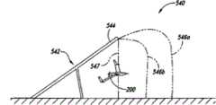
图5C是根据此公开的又一个实施方式配置的航空器回收系统540的部分示意图。该系统540包括被设置为拦截飞行中的无人航空器的细长弹性杆或航空器俘获构件542,其具有第一部分544和一个或多个第二部分546(以虚线546a和546b显示两个)。应当理解,该系统540可以只包括单一的第二部分546,或可以包括延伸自该第一部分542的超过两个第二部分546。该第二部分546的材料特性和特征可以大致类似于如上所述的该第二部分112/412。该系统540和如上所述的系统不同,因为该系统540的第二部分546a和546b不具有初始的大致线性和大致垂直布置的细长杆或航空器回收构件,它们初始为弯曲或非线性。此外,第二部分546a和546b各自具有连接该航空器俘获构件542的第一部分544的第一端,以及连接该局部表面(例如,地面)或另一适合结构的第二端。在若干实施方式中,该个别的第二部分546的第二端可以被设置为在各自的线中张力超过阈值时脱离或变为分离。在其它实施方式中,该个别的第二部分546的第二端可以保持自由,而不连接该局部表面或另一结构。在俘获和回收操作后,该第二部分546可以到达最终状态或布置(如线547所示),并且该航空器200可以从该线回收。FIG. 5C is a partial schematic diagram of an
根据上述内容,应当理解,已经描述于此的此公开的特定实施方式是为了说明,但在不偏离此公开的精神和范围前提下可以作出各种改变。例如,如上所述的该弹性杆可以具有伸缩式布置,该个别的竿的第二部分(和任何另外的部分)在操作前或后至少部分以收拢结构被容纳在该第一部分内。进一步地,如上所述的该弹性杆可以在该弹性杆的顶部或附近包括一个或多个接合构件(例如,钩子,环,多环,等等),并被设置为直接接合该航空器和/或接合该航空器所承载的俘获组件。此外,尽管如上所述的该航空器俘获构件具有大致竖直向上的定向,该弹性杆也可以大致向下的定向从适合的支持结构悬挂而下,用于俘获和回收操作。In light of the foregoing, it should be appreciated that particular embodiments of the disclosure have been described herein for purposes of illustration, but that various changes may be made without departing from the spirit and scope of the disclosure. For example, the resilient rod as described above may have a telescoping arrangement, the second part of the individual rod (and any further parts) being received within the first part at least partly in a collapsed configuration before or after operation. Further, the resilient rod as described above may include one or more engagement members (e.g., hooks, loops, multiple loops, etc.) at or near the top of the resilient rod and configured to directly engage the aircraft and/or Or engage capture components onboard the aircraft. Furthermore, while the aircraft capture member as described above has a generally vertical upward orientation, the resilient rod may also be suspended from a suitable support structure in a generally downward orientation for capture and recovery operations.
任何上述实施方式的特定部件可以被结合或或被其它实施方式中的部件代替。此外,尽管与此公开的某些实施方式有关的优点已经在这些实施方式的背景下被叙述,其它实施方式也可以展现这种优点,而不是,而不是所有的实施方式必须展现这种优点,以落入此公开的范围。相应地,除权利要求之外,此公开的实施方式不是限制性的。Specific components of any of the above-described embodiments may be combined or replaced by components of other embodiments. Furthermore, while advantages associated with certain embodiments of this disclosure have been recited in the context of these embodiments, other embodiments may exhibit such advantages, and not, and not all, embodiments must exhibit such advantages, fall within the scope of this disclosure. Accordingly, the disclosed embodiments are not to be restricted except by the claims.
Claims (25)
Translated fromChineseApplications Claiming Priority (3)
| Application Number | Priority Date | Filing Date | Title |
|---|---|---|---|
| US17266309P | 2009-04-24 | 2009-04-24 | |
| US61/172,663 | 2009-04-24 | ||
| PCT/US2010/032314WO2010138265A1 (en) | 2009-04-24 | 2010-04-23 | Systems and methods for recovering and controlling post-recovery motion of unmanned aircraft |
Publications (1)
| Publication Number | Publication Date |
|---|---|
| CN102625766Atrue CN102625766A (en) | 2012-08-01 |
Family
ID=42676005
Family Applications (1)
| Application Number | Title | Priority Date | Filing Date |
|---|---|---|---|
| CN2010800285307APendingCN102625766A (en) | 2009-04-24 | 2010-04-23 | Systems and methods for recovering and controlling post-recovery movement of an unmanned aerial vehicle |
Country Status (14)
| Country | Link |
|---|---|
| US (2) | US9944408B2 (en) |
| EP (1) | EP2421757B1 (en) |
| JP (1) | JP2012524695A (en) |
| KR (4) | KR101681348B1 (en) |
| CN (1) | CN102625766A (en) |
| AU (1) | AU2010254435B2 (en) |
| BR (1) | BRPI1014588B1 (en) |
| CA (1) | CA2759691C (en) |
| CL (1) | CL2011002646A1 (en) |
| IL (3) | IL215861A (en) |
| MX (1) | MX2011011247A (en) |
| SG (1) | SG175778A1 (en) |
| WO (1) | WO2010138265A1 (en) |
| ZA (1) | ZA201108346B (en) |
Cited By (6)
| Publication number | Priority date | Publication date | Assignee | Title |
|---|---|---|---|---|
| CN106742018A (en)* | 2016-11-20 | 2017-05-31 | 宁波市镇海丹发机械科技有限公司 | Retracting device on a kind of unmanned plane warship |
| CN109421939A (en)* | 2017-08-24 | 2019-03-05 | 极光飞行科学公司 | Track recovery system for aircraft |
| CN111216890A (en)* | 2014-07-28 | 2020-06-02 | 英西图公司 | System and method for counterattacking unmanned aerial vehicle |
| CN111232235A (en)* | 2014-11-20 | 2020-06-05 | 英西图公司 | Capture devices for unmanned aerial vehicles including track-carried capture lines and related systems and methods |
| CN113968338A (en)* | 2015-10-02 | 2022-01-25 | 英西图公司 | Aerial launch and/or recovery of unmanned aerial vehicles and related systems and methods |
| CN114013659A (en)* | 2018-02-19 | 2022-02-08 | Wing航空有限责任公司 | Carrier pickup device, carrier pickup system, and carrier pickup method |
Families Citing this family (43)
| Publication number | Priority date | Publication date | Assignee | Title |
|---|---|---|---|---|
| EP2421757B1 (en) | 2009-04-24 | 2013-10-23 | Insitu, Inc. | Systems and methods for recovering and controlling post-recovery motion of unmanned aircraft |
| US8573536B2 (en)* | 2010-03-26 | 2013-11-05 | Aerovel Corporation | Method and apparatus for automated launch, retrieval, and servicing of a hovering aircraft |
| US8944373B2 (en) | 2010-09-27 | 2015-02-03 | Insitu, Inc. | Line capture devices for unmanned aircraft, and associated systems and methods |
| JP2013060163A (en)* | 2011-09-15 | 2013-04-04 | Fuji Heavy Ind Ltd | Uninhabited aircraft recovery device |
| EP2766260A4 (en)* | 2011-10-12 | 2015-07-01 | Saab Ab | SYSTEM AND METHOD FOR LAUNCHING AND LANDING UAVs |
| AU2013204965B2 (en) | 2012-11-12 | 2016-07-28 | C2 Systems Limited | A system, method, computer program and data signal for the registration, monitoring and control of machines and devices |
| US10144511B2 (en) | 2013-04-02 | 2018-12-04 | Hood Technology Corporation | Helicopter-mediated system and method for launching and retrieving an aircraft |
| US9359075B1 (en) | 2013-04-02 | 2016-06-07 | Hood Technology Corporation | Helicopter-mediated system and method for launching and retrieving an aircraft |
| US10569868B2 (en)* | 2013-04-02 | 2020-02-25 | Hood Technology Corporation | Multicopter-assisted system and method for launching and retrieving a fixed-wing aircraft |
| US10583920B2 (en)* | 2013-04-02 | 2020-03-10 | Hood Technology Corporation | Multicopter-assisted system and method for launching and retrieving a fixed-wing aircraft |
| US9434481B2 (en) | 2013-09-23 | 2016-09-06 | Aerovel Corporation | Apparatus and method for launch and retrieval of a hovering aircraft |
| WO2015195175A2 (en)* | 2014-03-21 | 2015-12-23 | Borko Brandon | System for automatic takeoff and landing by interception of small uavs |
| WO2015168181A1 (en)* | 2014-04-29 | 2015-11-05 | Aerovironment, Inc. | Small unmanned aerial vehicle (suav) shipboard recovery system |
| US10414493B2 (en) | 2014-07-11 | 2019-09-17 | Aerovel Corporation | Apparatus and method for automated launch, retrieval, and servicing of a hovering aircraft |
| EP3222530B1 (en) | 2014-11-19 | 2020-12-16 | SZ DJI Technology Co., Ltd. | Positioning mechanism and uav base station using the positioning mechanism |
| WO2016167849A1 (en)* | 2015-01-15 | 2016-10-20 | Hood Technology Corporation | Helicopter-mediated system and method for launching and retrieving an aircraft |
| US20170057626A1 (en)* | 2015-08-25 | 2017-03-02 | Sikorsky Aircraft Corporation | Probe assemblies for aircraft securing systems |
| US10399702B2 (en) | 2016-03-15 | 2019-09-03 | Aerovel Corporation | Capture and launch apparatus and method of using same for automated launch, retrieval, and servicing of a hovering aircraft |
| US10752357B2 (en) | 2016-03-22 | 2020-08-25 | Hood Technology Corporation | Rotorcraft-assisted system and method for launching and retrieving a fixed-wing aircraft into and from free flight |
| US10407181B2 (en) | 2016-06-27 | 2019-09-10 | Insitu, Inc. | Locking line capture devices for unmanned aircraft, and associated systems and methods |
| US10696420B2 (en) | 2016-08-17 | 2020-06-30 | Hood Technology Corporation | Rotorcraft-assisted system and method for launching and retrieving a fixed-wing aircraft into and from free flight |
| US11204612B2 (en) | 2017-01-23 | 2021-12-21 | Hood Technology Corporation | Rotorcraft-assisted system and method for launching and retrieving a fixed-wing aircraft |
| US11524797B2 (en) | 2017-05-11 | 2022-12-13 | Hood Technology Corporation | Aircraft-retrieval system |
| US10988257B2 (en) | 2017-05-11 | 2021-04-27 | Hood Technology Corporation | Aircraft-retrieval system |
| WO2018222551A1 (en)* | 2017-05-31 | 2018-12-06 | Insitu, Inc. | Systems and methods for capturing and recovering unmanned aircraft |
| US10767682B2 (en) | 2017-06-29 | 2020-09-08 | Insitu, Inc. | Frangible fasteners with flexible connectors for unmanned aircraft, and associated systems and methods |
| US11667398B2 (en) | 2017-09-06 | 2023-06-06 | Hood Technology Corporation | Multicopter-assisted systems and methods for launching and retrieving a fixed-wing aircraft into and from free flight |
| US11027844B2 (en) | 2017-09-06 | 2021-06-08 | Hood Technology Corporation | Rotorcraft-assisted system for launching and retrieving a fixed-wing aircraft into and from free flight |
| US11414187B2 (en) | 2017-09-06 | 2022-08-16 | Hood Technology Corporation | Parasail-assisted systems and methods for launching and retrieving a fixed-wing aircraft into and from free flight |
| US11312492B1 (en) | 2017-11-09 | 2022-04-26 | Hood Technology Corporation | Rotorcraft-assisted systems and methods for launching and retrieving a fixed-wing aircraft into and from free flight |
| WO2019155854A1 (en)* | 2018-02-07 | 2019-08-15 | 国立大学法人大阪大学 | Multicopter system and method for transferring goods |
| US11066185B2 (en) | 2018-05-04 | 2021-07-20 | Insitu, Inc. | Launch and/or recovery for unmanned aircraft and/or other payloads, including via parachute-assist, and associated systems and methods |
| US11142339B2 (en) | 2018-05-04 | 2021-10-12 | Insitu, Inc. | Launch and/or recovery for unmanned aircraft and/or other payloads, including via parachute-assist, and associated systems and methods |
| CN109625305B (en)* | 2018-12-04 | 2024-02-13 | 青岛启航弹射科技有限公司 | Unmanned aerial vehicle recovery unit |
| US11518511B2 (en)* | 2019-03-06 | 2022-12-06 | Insitu, Inc. | Unmanned aerial vehicle (UAV) recovery |
| US11235892B2 (en) | 2019-05-22 | 2022-02-01 | Hood Technology Corporation | Aircraft retrieval system and method |
| FR3097207B1 (en) | 2019-06-17 | 2021-07-09 | De Perera Sylvain Roldan | AERIAL VECTOR RECOVERY SYSTEM |
| US11667396B2 (en)* | 2020-01-13 | 2023-06-06 | Insitu, Inc. | Methods and apparatus to stabilize and recover unmanned aerial vehicles (UAVs) |
| CN112373711B (en)* | 2020-11-20 | 2022-06-24 | 哈尔滨工业大学 | Self-adaptive active blocking type recovery adjusting device for fixed-wing unmanned aerial vehicle |
| UA125842C2 (en)* | 2021-02-17 | 2022-06-15 | Олександр Володимирович Степура | Device for catching and launching an unmanned aircraft |
| US12017795B2 (en) | 2022-04-14 | 2024-06-25 | The Boeing Company | Unmanned aerial vehicle launch and recovery |
| US12145753B2 (en)* | 2022-08-09 | 2024-11-19 | Pete Bitar | Compact and lightweight drone delivery device called an ArcSpear electric jet drone system having an electric ducted air propulsion system and being relatively difficult to track in flight |
| US11981453B1 (en)* | 2023-03-01 | 2024-05-14 | Fairtech Corporation | System for aerial vehicle landing and method for controlling system for aerial vehicle landing |
Citations (4)
| Publication number | Priority date | Publication date | Assignee | Title |
|---|---|---|---|---|
| CN1032645A (en)* | 1988-10-18 | 1989-05-03 | 黄泽荣 | Stol device for ultralight aircraft |
| US5054717A (en)* | 1989-05-03 | 1991-10-08 | Gec Marconi Limited | Aircraft capture systems |
| US20060249623A1 (en)* | 2005-05-05 | 2006-11-09 | Lockheed Martin Corporation | Robotically Assisted Launch/Capture Platform For An Unmanned Air Vehicle |
| WO2008015663A1 (en)* | 2006-07-31 | 2008-02-07 | Elbit Systems Ltd. | An unmanned aerial vehicle launching and landing system |
Family Cites Families (266)
| Publication number | Priority date | Publication date | Assignee | Title |
|---|---|---|---|---|
| US1624188A (en) | 1927-04-12 | Airplanes eeom and upon suspended | ||
| USRE16613E (en) | 1927-05-03 | Safety hook | ||
| US2735391A (en) | 1956-02-21 | H buschers | ||
| USRE25406E (en) | 1963-06-25 | Aircraft arresting system | ||
| US1317631A (en) | 1919-09-30 | kinser | ||
| US965881A (en) | 1909-12-03 | 1910-08-02 | George Otis Draper | Landing and starting apparatus for aeroplanes. |
| US968339A (en) | 1910-02-28 | 1910-08-23 | Gerald Geraldson | Aeroplane launcher and lander. |
| US975953A (en) | 1910-03-05 | 1910-11-15 | Iskander Hourwich | Aerial projecting apparatus. |
| US1164967A (en) | 1913-10-01 | 1915-12-21 | James M Thorp | Aeroplane alighting and launching apparatus. |
| US1144505A (en) | 1914-02-18 | 1915-06-29 | Frank Steffan | Aerial landing and launching appliance. |
| US1428163A (en) | 1917-06-23 | 1922-09-05 | James B Harriss | Launching and landing of aeroplanes |
| US1383595A (en) | 1920-02-25 | 1921-07-05 | Johnny S Black | Airplane landing and launching mechanism |
| US1384036A (en) | 1920-12-27 | 1921-07-12 | Anderson Gustaf | Device for launching aeroplanes from ships |
| US1716670A (en) | 1922-06-27 | 1929-06-11 | Lawrence Sperry Aircraft Compa | Device for launching and landing aeroplanes from and upon suspended positions |
| US1499472A (en) | 1922-07-14 | 1924-07-01 | Hazen C Pratt | Airplane-landing mechanism |
| US1738261A (en) | 1922-07-24 | 1929-12-03 | Willis B Perkins | Aeroplane-handling structure |
| US1816976A (en) | 1922-08-03 | 1931-08-04 | Eclipse Machine Co | Engine starting device for aeroplanes |
| US1532736A (en) | 1923-02-26 | 1925-04-07 | Flannery Bolt Co | Stay bolt for boilers |
| US1530010A (en) | 1924-10-01 | 1925-03-17 | Neilson Albert Howard | Safety hook |
| US1556348A (en) | 1925-02-14 | 1925-10-06 | Curtiss Aeroplane & Motor Co I | Aeroplane landing gear |
| US1869506A (en) | 1925-10-23 | 1932-08-02 | Holden C Richardson | Method of and apparatus for mooring an airplane while in flight to another aircraft |
| US1634964A (en) | 1925-12-29 | 1927-07-05 | Joseph A Steinmetz | Mooring dirigible aircraft |
| US1731091A (en) | 1926-08-05 | 1929-10-08 | Belleville Harry Clayton | Aircraft landing |
| US1749769A (en) | 1927-03-31 | 1930-03-11 | Fairchild Airplane Mfg Corp | Airplane-wing connection |
| US1712164A (en) | 1927-04-01 | 1929-05-07 | Peppin Joseph | Antiaircraft screen |
| US1686298A (en) | 1927-09-10 | 1928-10-02 | George E Ginter | Air or seaplane station |
| US1748663A (en) | 1927-09-20 | 1930-02-25 | Charles B Scoville Jr | Method and means for landing and launching aircraft and aircraft freight |
| US1680473A (en) | 1927-11-23 | 1928-08-14 | Parker Orin | Aeroplane landing and launching device |
| US1756747A (en) | 1928-06-12 | 1930-04-29 | Holland Lionel | Aeroplane-landing means |
| US1737483A (en) | 1928-09-18 | 1929-11-26 | Nicholas J Verret | Take-off and landing apparatus for aeroplanes |
| US1777167A (en) | 1928-11-09 | 1930-09-30 | Forbes William Archib Davidson | Apparatus for launching aircraft |
| US1825578A (en) | 1930-01-02 | 1931-09-29 | Cernuda Antonio | Airplane |
| US1836010A (en) | 1930-05-02 | 1931-12-15 | Constant A Audrain | Airplane landing and launching mechanism |
| US1842432A (en) | 1930-08-02 | 1932-01-26 | Samuel A Stanton | Landing and take-off apparatus for airplanes |
| US1925212A (en) | 1930-09-26 | 1933-09-05 | Arthur A Johnson | Means for facilitating the takingoff and landing of aircraft and refueling the same |
| US1940030A (en) | 1931-02-02 | 1933-12-19 | Arthur A Johnson | Means for facilitating the takingoff and landing of aircraft and refueling the same |
| US1912723A (en) | 1931-03-23 | 1933-06-06 | Willis B Perkins Jr | Airplane landing and launching appliance |
| US1892357A (en) | 1931-04-27 | 1932-12-27 | Edward E Moe | Airplane catapult |
| US1960264A (en) | 1931-10-11 | 1934-05-29 | Heinkel Ernst | Catapult for launching aeroplanes |
| US1909445A (en) | 1931-11-23 | 1933-05-16 | Hazel B Tidland | Parachute |
| US2211089A (en) | 1938-03-29 | 1940-08-13 | Curtiss Wright Corp | Wing and fuselage construction |
| FR854371A (en) | 1938-12-30 | 1940-04-11 | Schneider & Cie | Improvements to catapulting devices |
| US2515205A (en) | 1938-12-30 | 1950-07-18 | Fleux Jean | Catapult device for launching aerial machines |
| US2286381A (en) | 1939-03-14 | 1942-06-16 | Rubissow George Alexis | Method and device for forced takeoff and forced landing of airplanes and airships |
| US2296988A (en) | 1940-08-31 | 1942-09-29 | Waldemar A Endter | Hook type rotary latch |
| US2401853A (en) | 1941-06-23 | 1946-06-11 | Lockheed Aircraft Corp | Aerial torpedo |
| US2365827A (en) | 1941-08-05 | 1944-12-26 | Wingfoot Corp | Rigid airship |
| US2333559A (en) | 1941-08-15 | 1943-11-02 | Daniel W Grady | Airplane anchorage means |
| US2365778A (en) | 1941-09-16 | 1944-12-26 | Martin C Schwab | Mobile device for repelling the attack of enemy aircraft |
| US2342773A (en) | 1942-03-28 | 1944-02-29 | Samuel K Wellman | Landing platform for airplanes |
| US2390754A (en) | 1942-06-10 | 1945-12-11 | Diana Guest | Apparatus for handling airplanes |
| US2347561A (en) | 1942-07-02 | 1944-04-25 | Burton Rodgers Inc | Silhouette model |
| US2360220A (en) | 1943-01-16 | 1944-10-10 | Paul R Goldman | Knockdown decoy airplane and package |
| US2364527A (en) | 1943-04-13 | 1944-12-05 | Carroll M Haygood | Aircraft catching apparatus |
| US2436240A (en) | 1943-10-21 | 1948-02-17 | Anthony P Wiertz | Airplane landing gear |
| US2447945A (en) | 1944-05-05 | 1948-08-24 | Saunders Roe Ltd | Mooring gear for flying boats |
| US2380702A (en) | 1944-06-12 | 1945-07-31 | Meric C Persons | Airplane mooring appliance |
| US2435197A (en) | 1944-10-04 | 1948-02-03 | James H Brodie | Landing and launching apparatus for aircraft |
| US2465936A (en) | 1945-04-26 | 1949-03-29 | All American Airways Inc | Emergency arresting device for moving objects |
| US2526348A (en) | 1945-11-16 | 1950-10-17 | Saunders Roe Ltd | Pickup hook for flying boats |
| US2448209A (en) | 1946-01-23 | 1948-08-31 | Ail American Aviat Inc | Arresting unit for aircraft landing system |
| US2488051A (en) | 1948-01-15 | 1949-11-15 | James H Brodie | Aircraft landing apparatus |
| US2488050A (en) | 1948-01-15 | 1949-11-15 | James H Brodie | Aircraft landing system |
| US2814453A (en) | 1952-03-14 | 1957-11-26 | Glenn L Martin Co | Air base |
| US2671938A (en) | 1952-04-10 | 1954-03-16 | Roberts Malcolm | Self-locking hook |
| US2669403A (en) | 1952-07-21 | 1954-02-16 | Doris A Mckay | Glider carrying and releasing device for kites |
| US2787185A (en) | 1953-06-29 | 1957-04-02 | Boeing Co | Expansion fastener with sealing liner |
| US2843342A (en) | 1955-09-23 | 1958-07-15 | Task Corp | Mobile hydraulic catapulting apparatus |
| US2908240A (en) | 1956-02-07 | 1959-10-13 | Martin Co | Seaplane beaching apparatus |
| US2844340A (en) | 1956-10-16 | 1958-07-22 | All American Eng Co | Weight actuated arresting cable control means for aircraft |
| US2919871A (en) | 1956-11-15 | 1960-01-05 | All American Eng Co | Aircraft runway barriers |
| US2937827A (en) | 1957-01-28 | 1960-05-24 | Ralph E Duce | Counter-rotating propellers and dual engine safety system |
| US2933183A (en) | 1957-03-04 | 1960-04-19 | Vendo Co | Support structure for a missile or the like |
| US2954946A (en) | 1957-06-28 | 1960-10-04 | Edgar A O'neil | Apparatus for assisting the landing of aircraft |
| US3069118A (en) | 1959-05-28 | 1962-12-18 | Aerazur Constr Aeronaut | Means for arresting or stopping a landing aircraft such as compound net barriers |
| US3120831A (en) | 1960-10-07 | 1964-02-11 | Samuel K Fulton | Mooring whip |
| US3163380A (en) | 1961-06-02 | 1964-12-29 | James H Brodie | Aircraft launching apparatus |
| US3268090A (en) | 1965-08-23 | 1966-08-23 | Albert R Wirkkala | Articulated log skidder having a telescopic boom for throwing out the inhaul cable |
| DE1481982A1 (en) | 1965-12-01 | 1969-07-17 | Borgs Fabriks Ab | Aircraft barrier |
| GB1164371A (en) | 1966-03-31 | 1969-09-17 | Vsi Corp | Improvements in Blind Fasteners. |
| GB1117856A (en) | 1966-04-15 | 1968-06-26 | Karl Ove Torgny Walander | Arresting device for aircraft |
| US3484061A (en) | 1967-12-13 | 1969-12-16 | Bliss Co | Plural pendant vehicle arresting system |
| US3512447A (en) | 1968-09-09 | 1970-05-19 | Rudolph Marion Vaughn | Frangible nut fastener |
| GB1301097A (en) | 1969-03-28 | 1972-12-29 | Avdel Ltd | Blind fastener |
| US3939988A (en) | 1969-04-09 | 1976-02-24 | General Crane Industries Limited | Tower crane |
| US3516626A (en) | 1969-06-06 | 1970-06-23 | John S Strance | Aircraft launching system |
| US3589651A (en) | 1969-06-09 | 1971-06-29 | Gulf & Western Ind Prod Co | Aircraft arresting device |
| US3672214A (en) | 1969-10-09 | 1972-06-27 | Otis Elevator Co | Rope tension gauge for elevator system |
| SE347484B (en) | 1970-08-28 | 1972-08-07 | Borgs Fabriks Ab | |
| US3708200A (en) | 1970-12-17 | 1973-01-02 | D Richards | Combination house trailer and airplane hangar |
| US3684219A (en) | 1970-12-18 | 1972-08-15 | Robert W King | Glider launcher for kites |
| US3771484A (en) | 1972-04-14 | 1973-11-13 | Us Navy | Inflatable floating island |
| DE2330626A1 (en) | 1972-08-31 | 1974-03-07 | Industrial Acoustics Co | FASTENER WITH SECURITY |
| US4037807A (en) | 1972-09-01 | 1977-07-26 | Short Brothers And Harland Limited | Flight vehicle |
| GB1445835A (en) | 1972-10-04 | 1976-08-11 | Leckie R M P | Toy flying machines |
| US3827660A (en) | 1972-12-05 | 1974-08-06 | All American Ind | Aircraft arresting apparatus |
| GB1471583A (en) | 1974-04-03 | 1977-04-27 | British Aircraft Corp Ltd | Aircraft recovery means and method |
| US4079901A (en) | 1976-04-07 | 1978-03-21 | All American Industries, Inc. | Launching apparatus for flying device |
| US4067139A (en) | 1976-07-16 | 1978-01-10 | L. M. Cox Manufacturing Co., Inc. | Electric powered flying model airplane |
| FR2360467A1 (en) | 1976-08-05 | 1978-03-03 | Aerazur Constr Aeronaut | AIRCRAFT STOP NET |
| US4147317A (en) | 1977-06-23 | 1979-04-03 | All American Industries, Inc. | Mobile RPV landing deck |
| US4149840A (en) | 1977-11-08 | 1979-04-17 | Tippmann Eugene R | Apparatus for producing rigid foam plastic insulating panels |
| US4296898A (en) | 1977-12-23 | 1981-10-27 | Watson Ronald S | Anchor device for propeller rotator |
| USD256816S (en) | 1978-05-26 | 1980-09-09 | Cpg Products Corp. | Toy glider |
| US4236686A (en) | 1978-09-07 | 1980-12-02 | Grumman Aerospace Corporation | Ship compatible launch, retrieval and handling system for (VTOL) aircraft |
| DE2852220C2 (en) | 1978-12-02 | 1983-01-13 | Messerschmitt-Bölkow-Blohm GmbH, 8000 München | Horizontal landing arrangement for missiles |
| US4238093A (en) | 1978-12-21 | 1980-12-09 | The United States Of America As Represented By The Secretary Of The Navy | Aircraft launcher |
| US4279195A (en) | 1978-12-22 | 1981-07-21 | Fairchild Industries, Inc. | Collapsible launching system |
| DE2904749C2 (en) | 1979-02-08 | 1984-01-05 | Messerschmitt-Bölkow-Blohm GmbH, 8000 München | Missile in the manner of a drone |
| US4267987A (en) | 1979-03-29 | 1981-05-19 | Mcdonnell William R | Helicopter airborne load systems and composite aircraft configurations |
| DE2935044A1 (en) | 1979-08-30 | 1981-03-19 | Vereinigte Flugtechnische Werke Gmbh, 2800 Bremen | UNMANNED MISSILE TO BE LAUNCHED FROM A CONTAINER |
| US4311290A (en) | 1979-11-01 | 1982-01-19 | The United States Of America As Represented By The Secretary Of The Navy | Arrestment system |
| GB2080216A (en) | 1979-11-21 | 1982-02-03 | Elliott Brothers London Ltd | Apparatus for use in the recovery of a flying object |
| US4372016A (en) | 1980-07-03 | 1983-02-08 | Gulf & Western Manufacturing Company | Hardware snap and method of producing same |
| GB2093414A (en)* | 1981-02-24 | 1982-09-02 | British Aerospace | Apparatus for the collection and retardation of a moving body |
| AU550608B2 (en) | 1981-06-04 | 1986-03-27 | British Aerospace Public Limited Company | Retrieving and launching vtol planes by crane |
| US4730793A (en) | 1981-08-12 | 1988-03-15 | E-Systems, Inc. | Ordnance delivery system and method including remotely piloted or programmable aircraft with yaw-to-turn guidance system |
| DE3133339A1 (en) | 1981-08-22 | 1983-03-10 | Vereinigte Flugtechnische Werke Gmbh, 2800 Bremen | "UNMANNED MISSILE TO START FROM A CONTAINER" |
| FR2521520A1 (en) | 1982-02-15 | 1983-08-19 | Daude Martine | MARGINAL FINS WITH VARIABLE ANGLES OF ATTACK |
| US4678143A (en) | 1982-12-17 | 1987-07-07 | Frazer-Nash Ltd. | Launcher for remotely piloted aircraft |
| FR2538342B1 (en) | 1982-12-23 | 1986-05-16 | Messerschmitt Boelkow Blohm | DEVICE FOR RECOVERING FLYING BODIES WITHOUT EQUIPMENT |
| US4566658A (en) | 1983-08-01 | 1986-01-28 | The United States Of America As Represented By The Secretary Of The Navy | Aircraft barricade |
| GB2150895A (en) | 1983-11-07 | 1985-07-10 | Gq Defence Equip Ltd | Load deployment device |
| US4809933A (en) | 1984-02-21 | 1989-03-07 | Wickes Manufacturing Company | Portable aircraft arresting apparatus |
| US4653706A (en) | 1985-07-29 | 1987-03-31 | Youssef Ragiab | Emergency aircaft landing device |
| IL76726A (en) | 1985-10-16 | 1991-01-31 | Meir Yoffe | Method for point-landing of fixed-wing aircraft by means of cable reel-in |
| US4645241A (en) | 1985-12-10 | 1987-02-24 | Nicholas Sfikas | Laminating envelope |
| US4753400A (en) | 1987-02-13 | 1988-06-28 | Pioneer Systems, Incorporated | Shipboard air vehicle retrieval apparatus |
| US5039034A (en) | 1987-06-01 | 1991-08-13 | Indal Technologies Inc. | Apparatus for capturing, securing and traversing remotely piloted vehicles and methods therefor |
| US4790497A (en) | 1987-06-05 | 1988-12-13 | Meir Yoffe | Point-landing method for non vertical take off and landing flying objects |
| US5007875A (en) | 1987-10-02 | 1991-04-16 | Madhava Dasa | Multiple configuration model aircraft |
| CH676453A5 (en) | 1987-12-10 | 1991-01-31 | Eidgenoess Flugzeugwerk Emmen | |
| GB8814178D0 (en) | 1988-06-15 | 1988-11-16 | Marconi Gec Ltd | Aircraft recovery systems |
| US4991739A (en) | 1988-08-10 | 1991-02-12 | Coin Acceptors, Inc. | Vending machine |
| US4842222A (en) | 1988-09-19 | 1989-06-27 | Baird Eric A | Kite load-releasing device |
| US5687930A (en) | 1989-02-02 | 1997-11-18 | Indal Technologies Inc. | System and components useful in landing airborne craft |
| US4979701A (en) | 1989-03-01 | 1990-12-25 | Patron Inc. | Aircraft arresting elemental net with multiple independent bottom horizontal straps |
| DE3910621A1 (en) | 1989-04-01 | 1990-10-04 | Messerschmitt Boelkow Blohm | DEVICE FOR RECOVERING UNMANNED REUSABLE AIRCRAFT |
| FR2648199B1 (en) | 1989-06-09 | 1991-09-27 | Aerospatiale | TEMPORARY LINK DEVICE, PARTICULARLY FOR ARTIFICIAL SATELLITE APPENDIX, AND METHOD FOR RELEASING SUCH A LINK |
| US5042750A (en) | 1989-11-16 | 1991-08-27 | Datron, Inc. | Aircraft arresting system |
| FR2664233A1 (en) | 1990-07-06 | 1992-01-10 | Carrot Louis | SAFETY DEVICE FOR SURVIVAL OF STAFF ON BOARD AIRCRAFT. |
| US5119935A (en) | 1991-01-29 | 1992-06-09 | Grumman Aerospace Corporation | VTOL aircraft convertible shipping container and method of use |
| IL101069A (en) | 1991-02-25 | 1996-09-12 | Valsan Partners Purchase N Y | System for increasing airplane fuel mileage and airplane wing modification kit |
| US5145129A (en) | 1991-06-06 | 1992-09-08 | Grumman Aerospace Corporation | Unmanned boom/canard propeller v/stol aircraft |
| IT1251567B (en) | 1991-09-10 | 1995-05-17 | Riva Calzoni Spa | EQUIPMENT FOR TAKING, LOCKING AND HANDLING UNDERWATER AND SIMILAR VEHICLES. |
| US5176339A (en) | 1991-09-30 | 1993-01-05 | Lord Corporation | Resilient pivot type aircraft mounting |
| DE4301671A1 (en) | 1992-01-22 | 1993-07-29 | Nord Systemtechnik | Recovery system for drone etc. - has catch line held in frame to lock into hook held above drone, with retarding mounting for line. |
| WO1993015953A1 (en) | 1992-02-17 | 1993-08-19 | Takahashi, Toki | Device for landing airship or the like |
| US5222694A (en) | 1992-08-03 | 1993-06-29 | Atr International, Inc. | Aircraft interior panel noise dampening support brackets |
| CA2076151C (en) | 1992-08-14 | 1997-11-11 | John Brooke | System for handling a remotely operated vessel |
| US5253605A (en) | 1992-12-21 | 1993-10-19 | Applied Remote Technology, Inc. | Method and apparatus for deploying and recovering water borne vehicles |
| US5390550A (en) | 1993-05-26 | 1995-02-21 | Miller; George E. | Apparatus for measuring tension in stretched cables |
| DE4409424C1 (en) | 1994-03-18 | 1995-08-10 | Daimler Benz Aerospace Ag | Catchment device for flying objects |
| JPH07304498A (en) | 1994-05-13 | 1995-11-21 | Nec Corp | Recovering method and device for unmanned aircraft |
| US5603592A (en) | 1994-10-03 | 1997-02-18 | Huck International, Inc. | High strength blind bolt with uniform high clamp over an extended grip range |
| US5775289A (en) | 1995-05-12 | 1998-07-07 | Yamaha Hatsudoki Kabushiki Kaisha | Direct cylinder fuel injected engine |
| DE19602703A1 (en) | 1995-08-24 | 1997-02-27 | Udo Wagener | Twin=port, two=stroke, high=speed engine |
| US5816761A (en) | 1996-01-11 | 1998-10-06 | The Boeing Company | Lightweight structural blind fastener |
| US5655944A (en) | 1996-03-01 | 1997-08-12 | Fusselman; Robert M. | Packaging apparatus and aerial device formed from sheet material |
| US5762456A (en) | 1996-05-17 | 1998-06-09 | Asar Group, Inc. | Self tapping blind setting bolt rivet assembly |
| US5913479A (en) | 1996-09-18 | 1999-06-22 | Westwood, Iii; Samuel M. | Snap hook with pivotal gate |
| US6161797A (en) | 1996-11-25 | 2000-12-19 | Dugan Air Technologies, Inc. | Method and apparatus for reducing airplane noise |
| US5906336A (en) | 1997-11-14 | 1999-05-25 | Eckstein; Donald | Method and apparatus for temporarily interconnecting an unmanned aerial vehicle |
| DE69940161D1 (en) | 1998-06-18 | 2009-02-05 | Kline & Walker L L C | AUTOMATIC DEVICE FOR MONITORING EQUIPPED OPTIONS AND MACHINES WORLDWIDE |
| DE19837329C1 (en) | 1998-08-18 | 1999-11-11 | Daimler Chrysler Ag | Braking air bag for loading flight payloads |
| US6729275B2 (en) | 1999-02-05 | 2004-05-04 | Avl List Gmbh | Two-stroke internal combustion engine with crankcase scavenging |
| US6264140B1 (en) | 1999-06-08 | 2001-07-24 | Mcgeer Brian T. | Method for retrieving a fixed-wing aircraft without a runway |
| US20020100838A1 (en) | 1999-06-08 | 2002-08-01 | Mcgeer Brian T. | Method and apparatus for retrieving a flying object |
| AU782704B2 (en) | 1999-07-23 | 2005-08-25 | Advanced Aerospace Technologies, Inc. | Launch and recovery system for unmanned aerial vehicles |
| US6874729B1 (en) | 1999-07-23 | 2005-04-05 | Advanced Aerospace Technologies, Inc. | Launch and recovery system for unmanned aerial vehicles |
| US6343768B1 (en) | 2000-05-16 | 2002-02-05 | Patrick John Muldoon | Vertical/short take-off and landing aircraft |
| US6691649B2 (en) | 2000-07-19 | 2004-02-17 | Bombardier-Rotax Gmbh | Fuel injection system for a two-stroke engine |
| US6457673B1 (en) | 2000-08-16 | 2002-10-01 | Aai Corporation | Mobile aircraft launcher |
| US20020049447A1 (en) | 2000-08-29 | 2002-04-25 | Li Medical Technologies, Inc. | Expandable surgical fastener and method |
| US6442460B1 (en) | 2000-09-05 | 2002-08-27 | Hunter Engineering Company | Method and apparatus for networked wheel alignment communications and services |
| US6370455B1 (en) | 2000-09-05 | 2002-04-09 | Hunter Engineering Company | Method and apparatus for networked wheel alignment communications and service |
| US6371410B1 (en) | 2000-09-28 | 2002-04-16 | The United States Of America Represented By The Secretary Of The Navy | Emergency landing impact absorbing system for aircraft |
| US6416019B1 (en) | 2000-12-12 | 2002-07-09 | The United States Of America As Represented By The Secretary Of The Navy | Precision parachute recovery system |
| US6478650B1 (en) | 2001-09-28 | 2002-11-12 | 3E Enterprise Ltd. | Toy construction kit having movable members |
| AU2002334708A1 (en) | 2001-10-01 | 2003-04-14 | Kline And Walker, Llc | Pfn/trac system faa upgrades for accountable remote and robotics control |
| US6772488B1 (en) | 2001-10-11 | 2004-08-10 | Robert D. Jensen | Wire spring latch safety hook |
| CA2365754A1 (en) | 2001-12-14 | 2003-06-14 | S&C Electric Company | Rapid-release frangible fastener |
| US6908275B2 (en) | 2002-04-29 | 2005-06-21 | Charles Nelson | Fastener having supplemental support and retention capabilities |
| US6835045B1 (en) | 2002-05-10 | 2004-12-28 | Brent W. Barbee | Rotor blade protector |
| ITTO20020667A1 (en) | 2002-07-26 | 2004-01-26 | Fiat Ricerche | MICRO-AIRCRAFT VTOL |
| US7415917B2 (en) | 2002-08-29 | 2008-08-26 | Raytheon Company | Fixed deployed net for hit-to-kill vehicle |
| JP2004118370A (en) | 2002-09-25 | 2004-04-15 | Hitachi Ltd | Vehicle information collection system and method |
| US6626077B1 (en) | 2002-10-16 | 2003-09-30 | Mark David Gilbert | Intercept vehicle for airborne nuclear, chemical and biological weapons of mass destruction |
| US7128294B2 (en) | 2003-01-17 | 2006-10-31 | The Insitu Group, Inc. | Methods and apparatuses for launching unmanned aircraft, including methods and apparatuses for launching aircraft with a wedge action |
| US7175135B2 (en)* | 2003-01-17 | 2007-02-13 | The Insitu Group, Inc. | Methods and apparatuses for capturing unmanned aircraft and constraining motion of the captured aircraft |
| US7152827B2 (en) | 2003-01-17 | 2006-12-26 | The Insitu Group, Inc. | Methods and apparatuses for launching, capturing, and storing unmanned aircraft, including a container having a guide structure for aircraft components |
| US7165745B2 (en) | 2003-01-17 | 2007-01-23 | The Insitu Group, Inc. | Methods and apparatuses for launching unmanned aircraft, including releasably gripping aircraft during launch and braking subsequent grip motion |
| US7121507B2 (en) | 2003-01-17 | 2006-10-17 | The Insitu Group, Inc. | Methods and apparatuses for capturing and storing unmanned aircraft, including methods and apparatuses for securing the aircraft after capture |
| US7140575B2 (en) | 2003-01-17 | 2006-11-28 | The Insitu Group, Inc. | Methods and apparatuses for launching unmanned aircraft, including methods and apparatuses for releasably gripping aircraft during launch |
| US7090166B2 (en) | 2003-01-17 | 2006-08-15 | The Insitu Group, Inc. | Methods and apparatuses for launching unmanned aircraft, including methods and apparatuses for transmitting forces to the aircraft during launch |
| US7114680B2 (en) | 2003-01-17 | 2006-10-03 | The Insitu Group, Inc. | Methods and apparatuses for launching and capturing unmanned aircraft, including a combined launch and recovery system |
| US7059564B2 (en) | 2003-01-17 | 2006-06-13 | The Insitu Group, Inc. | Methods and apparatuses for capturing and recovering unmanned aircraft, including a cleat for capturing aircraft on a line |
| US7066430B2 (en) | 2003-01-17 | 2006-06-27 | The Insitu Group, Inc. | Methods and apparatuses for capturing and recovering unmanned aircraft, including extendable capture devices |
| RU2235045C1 (en) | 2003-02-05 | 2004-08-27 | Редников Валерий Васильевич | Flying vehicle |
| US6695255B1 (en) | 2003-03-07 | 2004-02-24 | Mohamed T. Husain | Emergency aircraft landing system |
| US6758440B1 (en) | 2003-03-21 | 2004-07-06 | Curtiss-Wright Electro-Mechanical Corporation | Electromagnetic aircraft arrestor system |
| US7143974B2 (en) | 2003-04-01 | 2006-12-05 | The Insitu Group, Inc. | Methods and apparatuses for launching airborne devices along flexible elongated members |
| US6925690B2 (en) | 2003-07-07 | 2005-08-09 | Jt International Distributors Inc. | Bullsnap |
| US7472461B2 (en) | 2003-12-01 | 2009-01-06 | Edward David Anstee | Lockable coupling hook |
| IL162915A (en) | 2004-07-08 | 2008-11-03 | Elbit Systems Ltd | Unmanned air vehicles and method of landing same |
| US7422178B2 (en) | 2004-10-21 | 2008-09-09 | Lockheed Martin Corporation | Non-threaded structural insert for component attachment |
| US7237750B2 (en) | 2004-10-29 | 2007-07-03 | L3 Communications | Autonomous, back-packable computer-controlled breakaway unmanned aerial vehicle (UAV) |
| US8367963B2 (en) | 2004-10-29 | 2013-02-05 | United Technologies Corporation | Method and apparatus for microplasma spray coating a portion of a turbine vane in a gas turbine engine |
| US7219856B2 (en) | 2005-02-04 | 2007-05-22 | Lockheed Martin Corporation | UAV recovery system |
| US20060271251A1 (en) | 2005-02-17 | 2006-11-30 | Hopkins Jeffrey A | Unmanned vehicle control |
| FR2883938B1 (en) | 2005-04-05 | 2009-10-09 | Zedel Soc Par Actions Simplifiee | AUTOMATIC LOCKING CARABINER |
| US7542828B2 (en) | 2005-07-01 | 2009-06-02 | Lockheed Martin Corporation | Unmanned air vehicle, integrated weapon platform, avionics system and control method |
| US7264204B1 (en) | 2005-12-12 | 2007-09-04 | The United States Of America As Represented By The Secretary Of The Navy | Unmanned aerial vehicle catcher |
| GB0526084D0 (en) | 2005-12-21 | 2006-02-01 | Airbus Uk Ltd | An aircraft structure and a fastener for use therewith |
| US7510145B2 (en) | 2006-01-06 | 2009-03-31 | Lockheed Martin Corporation | UAV recovery system II |
| US7510142B2 (en) | 2006-02-24 | 2009-03-31 | Stealth Robotics | Aerial robot |
| US20070261542A1 (en) | 2006-05-09 | 2007-11-15 | Chang Industry, Inc. | Airborne platform protection apparatus and associated system and method |
| US7954758B2 (en) | 2006-08-24 | 2011-06-07 | Aerovel Corporation | Method and apparatus for retrieving a hovering aircraft |
| US20080065401A1 (en) | 2006-09-11 | 2008-03-13 | Abrahamson James A | Method for meeting u.s. government security controls under export control regimes |
| US7740210B2 (en) | 2006-09-15 | 2010-06-22 | Newfrey Llc | Break-away bundling device |
| US7578467B2 (en) | 2006-10-30 | 2009-08-25 | Insitu, Inc. | Methods and apparatuses for indicating and/or adjusting tension in pliant tension members, including aircraft recovery lines |
| US7786417B2 (en) | 2006-12-11 | 2010-08-31 | Dese Research, Inc. | RAM neutralization system and method |
| US7686247B1 (en)* | 2006-12-22 | 2010-03-30 | Lockheed Martin Corporation | Vehicle recovery |
| US20080191091A1 (en) | 2007-02-09 | 2008-08-14 | Zachary Charles Hoisington | Method and device for retrieving aircraft |
| US20090314883A1 (en)* | 2007-05-10 | 2009-12-24 | Arlton Paul E | Uav launch and recovery system |
| US7806366B2 (en) | 2007-07-10 | 2010-10-05 | Insitu, Inc. | Systems and methods for capturing and controlling post-recovery motion of unmanned aircraft |
| US7798445B2 (en) | 2008-01-25 | 2010-09-21 | Insitu, Inc. | Systems and methods for recovering and controlling post-recovery motion of unmanned aircraft |
| US20090191019A1 (en) | 2008-01-29 | 2009-07-30 | Disney Enterprises, Inc. | Fastener safety retention |
| US8136766B2 (en) | 2008-02-01 | 2012-03-20 | Insitu, Inc. | Frangible fasteners for aircraft components and associated systems and methods |
| US8162256B2 (en)* | 2008-03-19 | 2012-04-24 | Honeywell International Inc. | Launch and capture systems for vertical take-off and landing (VTOL) vehicles |
| US8028952B2 (en)* | 2008-03-31 | 2011-10-04 | The Boeing Company | System for shipboard launch and recovery of unmanned aerial vehicle (UAV) aircraft and method therefor |
| US8348714B2 (en) | 2008-05-30 | 2013-01-08 | Mattel, Inc. | Toy flying aircraft |
| US8172177B2 (en) | 2008-06-02 | 2012-05-08 | Advanced Technology & Research Corp. | Stabilized UAV recovery system |
| US8205537B1 (en) | 2008-08-11 | 2012-06-26 | Raytheon Company | Interceptor projectile with net and tether |
| US8387540B2 (en) | 2008-08-11 | 2013-03-05 | Raytheon Company | Interceptor projectile and method of use |
| US8375837B2 (en) | 2009-01-19 | 2013-02-19 | Honeywell International Inc. | Catch and snare system for an unmanned aerial vehicle |
| US8038090B2 (en) | 2009-03-19 | 2011-10-18 | Aurora Flight Sciences Corporation | System and method for the retrieval of a smaller unmanned aerial vehicle by a larger unmanned aerial vehicle |
| US8100359B2 (en) | 2009-03-31 | 2012-01-24 | Qasem Awadh Al-Qaffas | Intercept system for falling bombs |
| EP2421757B1 (en)* | 2009-04-24 | 2013-10-23 | Insitu, Inc. | Systems and methods for recovering and controlling post-recovery motion of unmanned aircraft |
| AU2015275315B9 (en) | 2009-04-24 | 2018-02-08 | Insitu, Inc. | Systems and methods for recovering and controlling post-recovery motion of unmanned aircraft |
| CN101549754B (en) | 2009-04-29 | 2012-05-23 | 北京航空航天大学 | A rotary-fixed-wing composite aircraft and its design method |
| DE102009033032A1 (en) | 2009-07-02 | 2011-01-05 | Gartner Steel And Glass Gmbh | Rope anchorage with overload protection |
| IL201681A (en) | 2009-10-22 | 2014-06-30 | Abraham Abershitz | Uav system and method |
| WO2011066400A1 (en) | 2009-11-25 | 2011-06-03 | Aerovironment, Inc. | Automatic configuration control of a device |
| US8683770B2 (en) | 2009-12-03 | 2014-04-01 | The Steel Network, Inc. | Connector assembly for connecting building members |
| DE102010010508B4 (en) | 2010-03-06 | 2013-11-07 | Diehl Bgt Defence Gmbh & Co. Kg | Unmanned aerial vehicle with a payload space |
| US8556223B2 (en) | 2010-06-28 | 2013-10-15 | Electric Motion Company, Inc. | Break-away hook assembly |
| CN102384702A (en) | 2010-08-30 | 2012-03-21 | 北京理工大学 | Method for intercepting aircrafts without collateral damage in unmanned way |
| AU2011312463B2 (en) | 2010-09-27 | 2016-08-18 | Insitu, Inc. | Line capture devices for unmanned aircraft, and associated systems and methods |
| US8944373B2 (en) | 2010-09-27 | 2015-02-03 | Insitu, Inc. | Line capture devices for unmanned aircraft, and associated systems and methods |
| US9010683B2 (en) | 2011-09-30 | 2015-04-21 | Aurora Flight Sciences Corporation | Rail recovery system for aircraft |
| EP3564882B1 (en) | 2011-11-15 | 2021-10-27 | Insitu, Inc. | Method for limiting flying range of an unmanned aerial vehicle |
| IL219836A (en) | 2012-05-16 | 2017-02-28 | Meir Yoffe | Point take-off and landing of unmanned flying objects |
| US8991793B1 (en) | 2012-05-29 | 2015-03-31 | The Boeing Company | UAV capture of micro cargo aloft |
| US9085362B1 (en) | 2012-11-21 | 2015-07-21 | Lockheed Martin Corporation | Counter-unmanned aerial vehicle system and method |
| US9527392B2 (en) | 2013-03-14 | 2016-12-27 | Aurora Flight Sciences Corporation | Aerial system and vehicle for continuous operation |
| US9359075B1 (en) | 2013-04-02 | 2016-06-07 | Hood Technology Corporation | Helicopter-mediated system and method for launching and retrieving an aircraft |
| AU2015248219A1 (en) | 2014-01-14 | 2016-07-28 | Advanced Product Development, Llc | Asymmetric aircraft and their launch and recovery systems from small ships |
| CN106103276B (en) | 2014-03-25 | 2018-03-20 | 瓦斯菲·阿希达法特 | Air transportation service unmanned aerial vehicle |
| US10414493B2 (en) | 2014-07-11 | 2019-09-17 | Aerovel Corporation | Apparatus and method for automated launch, retrieval, and servicing of a hovering aircraft |
| US9932110B2 (en) | 2014-07-22 | 2018-04-03 | Jonathan McNally | Method for installing an object using an unmanned aerial vehicle |
| US9896222B2 (en) | 2014-11-20 | 2018-02-20 | Insitu, Inc. | Capture devices for unmanned aerial vehicles, including track-borne capture lines, and associated systems and methods |
| US10133272B2 (en) | 2015-05-07 | 2018-11-20 | The Boeing Company | Methods and apparatus to deploy and recover a fixed wing unmanned aerial vehicle via a non-fixed wing aircraft |
| US10933997B2 (en) | 2015-10-02 | 2021-03-02 | Insitu, Inc. | Aerial launch and/or recovery for unmanned aircraft, and associated systems and methods |
| US10407181B2 (en) | 2016-06-27 | 2019-09-10 | Insitu, Inc. | Locking line capture devices for unmanned aircraft, and associated systems and methods |
| US10836509B2 (en) | 2016-12-13 | 2020-11-17 | Insitu, Inc. | Aerial launch and/or recovery for unmanned aircraft, and associated systems and methods |
- 2010
- 2010-04-23EPEP10717370.0Apatent/EP2421757B1/enactiveActive
- 2010-04-23KRKR1020117027894Apatent/KR101681348B1/enactiveActive
- 2010-04-23JPJP2012507454Apatent/JP2012524695A/enactivePending
- 2010-04-23KRKR1020167032740Apatent/KR20160137685A/ennot_activeCeased
- 2010-04-23CACA2759691Apatent/CA2759691C/enactiveActive
- 2010-04-23BRBRPI1014588-5Apatent/BRPI1014588B1/enactiveIP Right Grant
- 2010-04-23KRKR1020197000060Apatent/KR102029637B1/enactiveActive
- 2010-04-23CNCN2010800285307Apatent/CN102625766A/enactivePending
- 2010-04-23WOPCT/US2010/032314patent/WO2010138265A1/enactiveApplication Filing
- 2010-04-23AUAU2010254435Apatent/AU2010254435B2/enactiveActive
- 2010-04-23KRKR1020187015837Apatent/KR101936340B1/enactiveActive
- 2010-04-23MXMX2011011247Apatent/MX2011011247A/ennot_activeApplication Discontinuation
- 2010-04-23SGSG2011077872Apatent/SG175778A1/enunknown
- 2011
- 2011-10-21USUS13/279,148patent/US9944408B2/enactiveActive
- 2011-10-23ILIL215861Apatent/IL215861A/enactiveIP Right Grant
- 2011-10-24CLCL2011002646Apatent/CL2011002646A1/enunknown
- 2011-11-14ZAZA2011/08346Apatent/ZA201108346B/enunknown
- 2015
- 2015-04-12ILIL238189Apatent/IL238189B/enactiveIP Right Grant
- 2018
- 2018-01-25ILIL257162Apatent/IL257162A/enactiveIP Right Grant
- 2018-03-12USUS15/918,624patent/US10843817B2/enactiveActive
Patent Citations (4)
| Publication number | Priority date | Publication date | Assignee | Title |
|---|---|---|---|---|
| CN1032645A (en)* | 1988-10-18 | 1989-05-03 | 黄泽荣 | Stol device for ultralight aircraft |
| US5054717A (en)* | 1989-05-03 | 1991-10-08 | Gec Marconi Limited | Aircraft capture systems |
| US20060249623A1 (en)* | 2005-05-05 | 2006-11-09 | Lockheed Martin Corporation | Robotically Assisted Launch/Capture Platform For An Unmanned Air Vehicle |
| WO2008015663A1 (en)* | 2006-07-31 | 2008-02-07 | Elbit Systems Ltd. | An unmanned aerial vehicle launching and landing system |
Cited By (10)
| Publication number | Priority date | Publication date | Assignee | Title |
|---|---|---|---|---|
| CN111216890A (en)* | 2014-07-28 | 2020-06-02 | 英西图公司 | System and method for counterattacking unmanned aerial vehicle |
| CN111216890B (en)* | 2014-07-28 | 2024-02-02 | 英西图公司 | System and method for countering a drone |
| CN111232235A (en)* | 2014-11-20 | 2020-06-05 | 英西图公司 | Capture devices for unmanned aerial vehicles including track-carried capture lines and related systems and methods |
| CN111232235B (en)* | 2014-11-20 | 2023-05-26 | 英西图公司 | Capture device for unmanned aerial vehicle including track-borne capture line and related systems and methods |
| CN113968338A (en)* | 2015-10-02 | 2022-01-25 | 英西图公司 | Aerial launch and/or recovery of unmanned aerial vehicles and related systems and methods |
| CN106742018A (en)* | 2016-11-20 | 2017-05-31 | 宁波市镇海丹发机械科技有限公司 | Retracting device on a kind of unmanned plane warship |
| CN109421939A (en)* | 2017-08-24 | 2019-03-05 | 极光飞行科学公司 | Track recovery system for aircraft |
| CN109421939B (en)* | 2017-08-24 | 2023-09-26 | 极光飞行科学公司 | Rail recovery system for aircraft |
| CN114013659A (en)* | 2018-02-19 | 2022-02-08 | Wing航空有限责任公司 | Carrier pickup device, carrier pickup system, and carrier pickup method |
| CN114013659B (en)* | 2018-02-19 | 2023-04-07 | Wing航空有限责任公司 | Carrier pickup device, carrier pickup system, and carrier pickup method |
Also Published As
| Publication number | Publication date |
|---|---|
| IL215861A (en) | 2015-04-30 |
| US20120223182A1 (en) | 2012-09-06 |
| IL238189B (en) | 2018-01-31 |
| US20180273204A1 (en) | 2018-09-27 |
| US9944408B2 (en) | 2018-04-17 |
| KR20160137685A (en) | 2016-11-30 |
| IL215861A0 (en) | 2012-01-31 |
| KR20180066267A (en) | 2018-06-18 |
| CL2011002646A1 (en) | 2012-06-22 |
| US10843817B2 (en) | 2020-11-24 |
| BRPI1014588A2 (en) | 2016-04-26 |
| CA2759691A1 (en) | 2010-12-02 |
| AU2010254435B2 (en) | 2015-09-24 |
| IL257162A (en) | 2018-03-29 |
| EP2421757B1 (en) | 2013-10-23 |
| BRPI1014588B1 (en) | 2020-06-30 |
| EP2421757A1 (en) | 2012-02-29 |
| KR20190003861A (en) | 2019-01-09 |
| ZA201108346B (en) | 2013-01-30 |
| KR102029637B1 (en) | 2019-10-07 |
| KR101936340B1 (en) | 2019-01-08 |
| JP2012524695A (en) | 2012-10-18 |
| MX2011011247A (en) | 2012-04-11 |
| CA2759691C (en) | 2019-06-04 |
| KR101681348B1 (en) | 2016-11-30 |
| WO2010138265A1 (en) | 2010-12-02 |
| KR20120014002A (en) | 2012-02-15 |
| AU2010254435A1 (en) | 2011-12-01 |
| SG175778A1 (en) | 2011-12-29 |
Similar Documents
| Publication | Publication Date | Title |
|---|---|---|
| US10843817B2 (en) | Systems and methods for recovering and controlling post-recovery motion of unmanned aircraft | |
| US11053024B2 (en) | Capture devices for unmanned aerial vehicles, including track-borne capture lines, and associated systems and methods | |
| EP1233905B1 (en) | Launch and recovery system for unmanned aerial vehicles | |
| US9527604B2 (en) | Unmanned air vehicle recovery system | |
| US6874729B1 (en) | Launch and recovery system for unmanned aerial vehicles | |
| US20160251088A1 (en) | Unmanned air vehicle recovery system | |
| US20180086481A1 (en) | UAV Capture System | |
| US11492141B2 (en) | Systems and methods for capturing and recovering unmanned aircraft | |
| EP4112458B1 (en) | Methods and apparatus to recover unmanned aerial vehicles with kites | |
| AU2015275315B2 (en) | Systems and methods for recovering and controlling post-recovery motion of unmanned aircraft |
Legal Events
| Date | Code | Title | Description |
|---|---|---|---|
| C06 | Publication | ||
| PB01 | Publication | ||
| C10 | Entry into substantive examination | ||
| SE01 | Entry into force of request for substantive examination | ||
| C02 | Deemed withdrawal of patent application after publication (patent law 2001) | ||
| WD01 | Invention patent application deemed withdrawn after publication | Application publication date:20120801 |