CN102624018B - Distributed hybrid power supply type smart grid system and control method - Google Patents
Distributed hybrid power supply type smart grid system and control methodDownload PDFInfo
- Publication number
- CN102624018B CN102624018BCN201210094291.6ACN201210094291ACN102624018BCN 102624018 BCN102624018 BCN 102624018BCN 201210094291 ACN201210094291 ACN 201210094291ACN 102624018 BCN102624018 BCN 102624018B
- Authority
- CN
- China
- Prior art keywords
- batteries
- voltage
- power supply
- protection
- signal
- Prior art date
- Legal status (The legal status is an assumption and is not a legal conclusion. Google has not performed a legal analysis and makes no representation as to the accuracy of the status listed.)
- Expired - Fee Related
Links
Images


Classifications
- H—ELECTRICITY
- H02—GENERATION; CONVERSION OR DISTRIBUTION OF ELECTRIC POWER
- H02J—CIRCUIT ARRANGEMENTS OR SYSTEMS FOR SUPPLYING OR DISTRIBUTING ELECTRIC POWER; SYSTEMS FOR STORING ELECTRIC ENERGY
- H02J7/00—Circuit arrangements for charging or depolarising batteries or for supplying loads from batteries
- H02J7/0013—Circuit arrangements for charging or depolarising batteries or for supplying loads from batteries acting upon several batteries simultaneously or sequentially
- H02J7/0024—Parallel/serial switching of connection of batteries to charge or load circuit
- H—ELECTRICITY
- H02—GENERATION; CONVERSION OR DISTRIBUTION OF ELECTRIC POWER
- H02J—CIRCUIT ARRANGEMENTS OR SYSTEMS FOR SUPPLYING OR DISTRIBUTING ELECTRIC POWER; SYSTEMS FOR STORING ELECTRIC ENERGY
- H02J3/00—Circuit arrangements for AC mains or AC distribution networks
- H02J3/28—Arrangements for balancing of the load in a network by storage of energy
- H02J3/32—Arrangements for balancing of the load in a network by storage of energy using batteries with converting means
- H—ELECTRICITY
- H02—GENERATION; CONVERSION OR DISTRIBUTION OF ELECTRIC POWER
- H02J—CIRCUIT ARRANGEMENTS OR SYSTEMS FOR SUPPLYING OR DISTRIBUTING ELECTRIC POWER; SYSTEMS FOR STORING ELECTRIC ENERGY
- H02J3/00—Circuit arrangements for AC mains or AC distribution networks
- H02J3/38—Arrangements for parallely feeding a single network by two or more generators, converters or transformers
- H02J3/381—Dispersed generators
- H—ELECTRICITY
- H02—GENERATION; CONVERSION OR DISTRIBUTION OF ELECTRIC POWER
- H02J—CIRCUIT ARRANGEMENTS OR SYSTEMS FOR SUPPLYING OR DISTRIBUTING ELECTRIC POWER; SYSTEMS FOR STORING ELECTRIC ENERGY
- H02J3/00—Circuit arrangements for AC mains or AC distribution networks
- H02J3/38—Arrangements for parallely feeding a single network by two or more generators, converters or transformers
- H02J3/46—Controlling of the sharing of output between the generators, converters, or transformers
- H—ELECTRICITY
- H02—GENERATION; CONVERSION OR DISTRIBUTION OF ELECTRIC POWER
- H02J—CIRCUIT ARRANGEMENTS OR SYSTEMS FOR SUPPLYING OR DISTRIBUTING ELECTRIC POWER; SYSTEMS FOR STORING ELECTRIC ENERGY
- H02J2300/00—Systems for supplying or distributing electric power characterised by decentralized, dispersed, or local generation
- H02J2300/20—The dispersed energy generation being of renewable origin
- H02J2300/22—The renewable source being solar energy
- H02J2300/24—The renewable source being solar energy of photovoltaic origin
- H—ELECTRICITY
- H02—GENERATION; CONVERSION OR DISTRIBUTION OF ELECTRIC POWER
- H02J—CIRCUIT ARRANGEMENTS OR SYSTEMS FOR SUPPLYING OR DISTRIBUTING ELECTRIC POWER; SYSTEMS FOR STORING ELECTRIC ENERGY
- H02J2300/00—Systems for supplying or distributing electric power characterised by decentralized, dispersed, or local generation
- H02J2300/20—The dispersed energy generation being of renewable origin
- H02J2300/28—The renewable source being wind energy
- H—ELECTRICITY
- H02—GENERATION; CONVERSION OR DISTRIBUTION OF ELECTRIC POWER
- H02J—CIRCUIT ARRANGEMENTS OR SYSTEMS FOR SUPPLYING OR DISTRIBUTING ELECTRIC POWER; SYSTEMS FOR STORING ELECTRIC ENERGY
- H02J2300/00—Systems for supplying or distributing electric power characterised by decentralized, dispersed, or local generation
- H02J2300/40—Systems for supplying or distributing electric power characterised by decentralized, dispersed, or local generation wherein a plurality of decentralised, dispersed or local energy generation technologies are operated simultaneously
- Y—GENERAL TAGGING OF NEW TECHNOLOGICAL DEVELOPMENTS; GENERAL TAGGING OF CROSS-SECTIONAL TECHNOLOGIES SPANNING OVER SEVERAL SECTIONS OF THE IPC; TECHNICAL SUBJECTS COVERED BY FORMER USPC CROSS-REFERENCE ART COLLECTIONS [XRACs] AND DIGESTS
- Y02—TECHNOLOGIES OR APPLICATIONS FOR MITIGATION OR ADAPTATION AGAINST CLIMATE CHANGE
- Y02E—REDUCTION OF GREENHOUSE GAS [GHG] EMISSIONS, RELATED TO ENERGY GENERATION, TRANSMISSION OR DISTRIBUTION
- Y02E10/00—Energy generation through renewable energy sources
- Y02E10/50—Photovoltaic [PV] energy
- Y02E10/56—Power conversion systems, e.g. maximum power point trackers
Landscapes
- Engineering & Computer Science (AREA)
- Power Engineering (AREA)
- Charge And Discharge Circuits For Batteries Or The Like (AREA)
Abstract
Translated fromChineseDescription
Translated fromChinese技术领域technical field
本发明属于新能源发电与电气技术领域,具体涉及一种分布式混合供电型智能电网系统及控制方法。The invention belongs to the field of new energy power generation and electrical technology, and in particular relates to a distributed hybrid power supply type smart grid system and a control method.
背景技术Background technique
随着能源危机日益严重,环境问题日益突出,清洁、可再生的新能源发电技术成为人们关注的热点,作为利用新能源方式的一种——新能源分布式发电系统的发展是热点中的热点。新能源分布式发电系统的特点就是系统自身发出的电能容量很小,分布于负荷附近,主要是满足周边负荷用电为目的的发电系统。不同于传统集中式发电、输电和配电的用电方式,分布式发电系统由于就地发电、就地消纳,大大降低了电能输送带来的损耗和环境问题,解决为了满足负荷增长进行电力网升级产生的架线走廊紧缺的问题。此外,分布式发电系统的加入提升了供电网络的可靠性。With the increasingly severe energy crisis and increasingly prominent environmental problems, clean and renewable new energy power generation technology has become a hot spot of concern. As a way to utilize new energy—the development of new energy distributed power generation systems is a hot spot among hot spots . The characteristic of the new energy distributed power generation system is that the power capacity generated by the system itself is very small, distributed near the load, and it is mainly a power generation system for the purpose of satisfying the power consumption of the surrounding load. Different from the traditional centralized power generation, power transmission and power distribution, the distributed power generation system greatly reduces the loss and environmental problems caused by power transmission due to on-site power generation and on-site consumption, and solves the problem of power network in order to meet the load growth. The shortage of wired corridors caused by the upgrade. In addition, the addition of a distributed generation system improves the reliability of the power supply network.
新能源分布式发电作为新一代发电技术,涉及的相关技术具体有:最大功率跟踪技术、电能质量治理技术、孤岛检测技术和相关保护系统的构建技术等等。虽然传统的电力系统对上述的问题做出了深远的研究,但是新能源作为分布式发电系统的原动力,自身的间歇性、波动性和随机性等特点,输出的电能的性质与传统的以‘大火电、大水电’作为电能原动力输出的电能会有本质的区别。这样就要求电力研究人员在传统电力发展的基础之上,结合新能源分布式并网发电系统的独特性做出技术革新。As a new generation of power generation technology, new energy distributed power generation involves related technologies such as: maximum power tracking technology, power quality management technology, island detection technology and related protection system construction technology, etc. Although the traditional power system has made far-reaching research on the above-mentioned problems, new energy, as the driving force of the distributed power generation system, has its own intermittent, fluctuating and random characteristics, and the nature of the output power is different from that of the traditional one. Large thermal power and large hydropower will have essential differences in the output of electric energy as the driving force of electric energy. This requires electric power researchers to make technical innovations based on the traditional power development and the uniqueness of new energy distributed grid-connected power generation systems.
目前,分布式发电系统的主要新能源是风能和太阳能,这是由于风能、太阳能资源储量丰富、而且相关的发电设备——风力发电机和光伏电池板,都已经相当成熟。但是现在的技术主要是集中在大容量的风能和太阳能发电系统的方面。关于风光互补型分布式并网发电系统的技术还处于研究阶段,逆变输出电能的质量差、功率波动大和电能频率不稳定等问题,一直是阻碍风光互补型分布式并网发电系统发展的主要因素。At present, the main new energy sources of distributed power generation systems are wind energy and solar energy. This is due to the abundant reserves of wind energy and solar energy resources, and the related power generation equipment - wind turbines and photovoltaic panels, are quite mature. But current technologies are mainly focused on large-capacity wind and solar power generation systems. The technology of wind-solar complementary distributed grid-connected power generation system is still in the research stage. Problems such as poor quality of inverter output power, large power fluctuations, and unstable power frequency have always been the main obstacles to the development of wind-solar complementary distributed grid-connected power generation systems. factor.
发明内容Contents of the invention
针对现有装置存在的不足,本发明提出一种分布式混合供电型智能电网系统,以达到提高能源利用效率、提高逆变电能质量和使系统运行稳定性的目的。Aiming at the deficiencies of the existing devices, the present invention proposes a distributed hybrid power supply type smart grid system to achieve the purpose of improving energy utilization efficiency, improving inverter power quality and making the system run stably.
本发明的技术方案是这样实现的:一种分布式混合供电型智能电网系统,包括:发电单元、直流汇流单元、储能单元、逆变单元、并网控制单元、本地交、直流负载,其中,所述的储能单元还包括:蓄电池储能装置;The technical solution of the present invention is realized as follows: a distributed hybrid power supply type smart grid system, including: a power generation unit, a DC confluence unit, an energy storage unit, an inverter unit, a grid-connected control unit, and local AC and DC loads, wherein , the energy storage unit also includes: a battery energy storage device;
所述的蓄电池储能装置包括三层结构,第一层包括至少两个蓄电池组,以其中一个蓄电池组为首,其余蓄电池组横向排列,构成第一层结构,连接规则为:The battery energy storage device includes a three-layer structure. The first layer includes at least two battery groups, with one battery group as the head, and the remaining battery groups are arranged horizontally to form the first layer structure. The connection rules are as follows:
(1)首端蓄电池组的正极输入端与末端蓄电池组的正极输出端连接;首端蓄电池组的负极输入端与末端蓄电池组的负极输出端连接,且在其连接导线上设置有开关;(1) The positive input terminal of the first battery pack is connected to the positive output terminal of the last battery pack; the negative input terminal of the first battery pack is connected to the negative output terminal of the last battery pack, and a switch is provided on the connecting wire;
(2)位于首端和末端中间的蓄电池组,其连接方式为:前一个蓄电池组的正极输出端连接后一个蓄电池组的正极输入端;前一个蓄电池组的负极输出端连接后一个蓄电池组的负极输入端,且在其连接导线上设置有开关;(2) The battery pack located between the head end and the end is connected in the following way: the positive output terminal of the previous battery pack is connected to the positive input terminal of the next battery pack; the negative output terminal of the previous battery pack is connected to the Negative input terminal, and a switch is provided on its connecting wire;
第二层包括至少两个蓄电池组,且该层蓄电池组的数目与第一层中蓄电池组的数目相同,以其中一个蓄电池组为首,其余蓄电池组横向排列,并依次与第一层中的蓄电池组纵向对齐,构成第二层结构,连接规则为:The second layer includes at least two storage battery groups, and the number of storage battery groups in this layer is the same as the number of storage battery groups in the first layer, with one of the storage battery groups as the head, and the remaining storage battery groups are arranged horizontally, and are sequentially connected with the storage battery groups in the first layer. The groups are vertically aligned to form the second layer structure, and the connection rules are:
(3)首端蓄电池组的负极输入端连接充电电源的负极,且在连接导线上设置有开关;末端蓄电池组的正极输入端连接充电电源的正极,且在连接导线上设置有开关;(3) The negative input terminal of the battery pack at the first end is connected to the negative pole of the charging power supply, and a switch is provided on the connecting wire; the positive input terminal of the terminal battery pack is connected to the positive pole of the charging power supply, and a switch is provided on the connecting wire;
(4)位于首段和末端中间的蓄电池组,如果数量是奇数,则蓄电池组的负极输入端连接充电电源的负极,且在连接导线上设置有开关;如果数量是偶数,则蓄电池组的正极输入端连接充电电源的正极,且在连接导线上设置有开关;(4) For the battery pack located between the first section and the end, if the number is odd, the negative input terminal of the battery pack is connected to the negative pole of the charging power supply, and a switch is provided on the connecting wire; if the number is even, the positive pole of the battery pack is The input terminal is connected to the positive pole of the charging power supply, and a switch is arranged on the connecting wire;
对于第二层中所有的蓄电池组,均满足如下连接方式:蓄电池组的正极输出端连接第一层中与它纵向对齐的蓄电池组的正极输入端;蓄电池组的负极输出端连接第一层中与它纵向对齐的蓄电池组的负极输入端,且在连接导线上设置有开关;For all the battery packs in the second layer, the following connection methods are met: the positive output end of the battery pack is connected to the positive input end of the battery pack in the first layer that is longitudinally aligned with it; the negative output end of the battery pack is connected to the battery pack in the first layer. The negative input terminal of the battery pack aligned longitudinally with it, and a switch is provided on the connecting wire;
第三层包括至少一个蓄电池组,连接规则为:The third layer includes at least one battery pack, and the connection rules are:
(5)蓄电池组的负极输入端连接充电电源的负极;蓄电池组的正极输入端连接充电电源的正极;(5) The negative input terminal of the battery pack is connected to the negative pole of the charging power supply; the positive input terminal of the battery pack is connected to the positive pole of the charging power supply;
(6)该层蓄电池组的正极输入端依次连接第二层中蓄电池组的正极输入端,且在干路导线上设置一个总开关,在各支路导线上分别设置有分开关;该层蓄电池组的负极输入端依次连接第二层中蓄电池组的负极输入端,且在干路导线上设置一个总开关;(6) The positive input terminal of the storage battery pack in this layer is connected to the positive input terminal of the storage battery pack in the second layer in turn, and a main switch is set on the main circuit wire, and a branch switch is respectively provided on each branch circuit wire; the battery pack in this layer The negative input terminal of the battery pack is sequentially connected to the negative input terminal of the storage battery pack in the second layer, and a main switch is set on the trunk wire;
该层蓄电池组的正极输出端依次连接第二层中蓄电池组的正极输入端,且在连接导线上设置有开关;该层蓄电池组的负极输出端依次连接第二层中蓄电池组的负极输入端;The positive output terminal of the storage battery group in this layer is connected to the positive input terminal of the storage battery group in the second layer in turn, and a switch is arranged on the connecting wire; the negative output terminal of the storage battery group in this layer is connected in sequence to the negative input terminal of the storage battery group in the second layer ;
分布式混合供电型智能电网系统的控制方法,包括蓄电池充电控制方法、过电流保护方法、过电压保护方法、过欠频保护方法和黑启动方法;A control method for a distributed hybrid power supply type smart grid system, including a battery charging control method, an overcurrent protection method, an overvoltage protection method, an over-underfrequency protection method, and a black start method;
其中,所述的蓄电池充电控制方法,包括以下步骤:Wherein, the described accumulator charging control method comprises the following steps:
步骤1-1:电压互感器采集蓄电池储能装置的电压信息;Step 1-1: The voltage transformer collects the voltage information of the battery energy storage device;
步骤1-2:采集的电压信息通过信号调制电路转换为电信号,送入DSP的A/D转化器进行模数转换,记录每一个采样端的电压值,保存在数据储存器中;Step 1-2: The collected voltage information is converted into an electrical signal through a signal modulation circuit, sent to the A/D converter of the DSP for analog-to-digital conversion, and the voltage value of each sampling terminal is recorded and stored in the data memory;
步骤1-3:DSP将A/D转换后的电压值传输到单片机中;Step 1-3: DSP transmits the voltage value after A/D conversion to the microcontroller;
步骤1-4:采样端的电压值与电压值13.6V进行比较,若采样端的电压值大于13.6V,则采用恒压法对蓄电池组进行充电,执行步骤1-5;若采样端的电压值小于13.6V,则采用浮充法对蓄电池组进行充电,执行步骤1-6;Step 1-4: Compare the voltage value of the sampling terminal with the voltage value 13.6V, if the voltage value of the sampling terminal is greater than 13.6V, use the constant voltage method to charge the battery pack, and perform steps 1-5; if the voltage value of the sampling terminal is less than 13.6V V, then use the float charging method to charge the battery pack, and perform steps 1-6;
步骤1-5:采用恒压法对蓄电池组进行充电,过程为:将第一层、第二层纵向对齐的两个蓄电池组作为一个充电单元,将需要充电的充电单元接入充电电源,进行恒压充电,其余的充电单元不接入;Step 1-5: Use the constant voltage method to charge the battery pack. The process is: use the two battery packs aligned vertically on the first layer and the second layer as a charging unit, connect the charging unit that needs to be charged to the charging power source, and carry out Constant voltage charging, the rest of the charging units are not connected;
步骤1-6:采用浮充法对蓄电池组进行充电,过程是:将第一层、第二层纵向对齐的两个蓄电池组和第三层中的蓄电池组作为一个充电单元,将需要充电的充电单元接入充电电源,进行浮充充电,其余的充电单元不接入;Step 1-6: Use the float charging method to charge the battery pack, the process is: use the two battery packs vertically aligned on the first layer and the second layer and the battery pack in the third layer as a charging unit, and charge the battery pack that needs to be charged The charging unit is connected to the charging power supply for floating charging, and the rest of the charging units are not connected;
步骤1-7:结束。Steps 1-7: End.
过电流保护方法、过电压保护方法、过欠频保护方法,包括以下步骤:The overcurrent protection method, the overvoltage protection method, and the over-underfrequency protection method include the following steps:
步骤2-1:输入保护系统的整定值,包括:过电流的整定值范围、过电流延时、步进、过电压的整定值范围、过电压延时、步进、过欠频的整定值范围、延时、整定级差;Step 2-1: Input the setting value of the protection system, including: setting value range of overcurrent, overcurrent delay, step, setting value range of overvoltage, overvoltage delay, step, setting value of over frequency and under frequency Range, delay, setting difference;
步骤2-2:系统中的电压互感器采集电压信号、电流互感器采集电流信号;Step 2-2: The voltage transformer in the system collects the voltage signal, and the current transformer collects the current signal;
步骤2-3:互感器采集的信号送入信号调制电路转换为可被DSP接收的电信号;Step 2-3: The signal collected by the transformer is sent to the signal modulation circuit to be converted into an electrical signal that can be received by the DSP;
步骤2-4:将逆变器输出端的某一相电压信号送入同步信号的过零检测电路,将电压正弦波转换为方波信号;Step 2-4: Send a certain phase voltage signal at the inverter output terminal to the zero-crossing detection circuit of the synchronous signal, and convert the voltage sine wave into a square wave signal;
步骤2-5:转换后的信号送入DSP的A/D转换器进行A/D转换,其中,相电压的方波信号送入DSP的计数单元,测量逆变电能的频率,并将转换和测量的数据存入数据存储器;Step 2-5: The converted signal is sent to the A/D converter of the DSP for A/D conversion, wherein the square wave signal of the phase voltage is sent to the counting unit of the DSP, the frequency of the inverter electric energy is measured, and the converted and The measured data is stored in the data memory;
步骤2-6:DSP将采样得到的系统运行的电压、电流、频率信号通过液晶显示器显示;Step 2-6: The DSP displays the voltage, current, and frequency signals of the system operation obtained by sampling through the liquid crystal display;
步骤2-7:将DSP的储存数据通过串口传输到单片机中;Step 2-7: Transfer the stored data of the DSP to the MCU through the serial port;
步骤2-8:进行过电流保护、过电压保护和过欠频保护,所述的过电流保护过程如下:单片机对接收到的数据进行处理,判断采集到的数据是否在过电流保护整定值的范围内,若是,则单片机发出的信号,通过光电耦合器后加在继电器上,控制断路器跳闸,完成继电保护;若否,则不进行操作,执行步骤2-9;Step 2-8: Carry out over-current protection, over-voltage protection and over-under-frequency protection. The over-current protection process is as follows: the single-chip microcomputer processes the received data, and judges whether the collected data is within the set value of over-current protection. Within the range, if yes, then the signal sent by the single-chip microcomputer is added to the relay after passing through the photocoupler, and the circuit breaker is controlled to trip, and the relay protection is completed; if not, no operation is performed, and steps 2-9 are performed;
过电压保护过程如下:单片机对接收到数据进行处理,判断采集到的数据是否在过电压保护整定值范围内,若是,单片机发出的信号通过光电耦合器后加在继电器上,控制断路器跳闸,完成继电保护;若否,则不进任何操作,执行步骤2-9;The over-voltage protection process is as follows: the single-chip microcomputer processes the received data, and judges whether the collected data is within the range of the over-voltage protection setting value. If so, the signal sent by the single-chip microcomputer is added to the relay after passing through the photocoupler, and the circuit breaker is controlled to trip. Complete the relay protection; if not, do not perform any operation, and perform steps 2-9;
过欠频保护过程如下:一个采样周期后,单片机对新的采样数据进行处理,判断采集到的数据是否在过欠频保护整定值的范围内,若是,单片机发出PWM波控制储能单元控制器,使得飞轮储能装置接入系统进行放电,调整并网电能的频率;若否,则不进任何操作,执行步骤2-9;;The over-underfrequency protection process is as follows: After one sampling period, the single-chip microcomputer processes the new sampling data to determine whether the collected data is within the range of over-underfrequency protection setting values. If so, the single-chip microcomputer sends PWM waves to control the energy storage unit controller , so that the flywheel energy storage device is connected to the system for discharge, and the frequency of grid-connected electric energy is adjusted; if not, no operation is performed, and steps 2-9 are performed;
再经过一个采样周期后,单片机对新的采样数据数据进行处理,判断采集到的数据是否在过欠频保护整定值的范围内,若否,则不进任何操作,执行步骤2-9;,若是,单片机发出的信号通过光电耦合器后加在继电器上,控制断路器断开,完成继电保护;After another sampling period, the single-chip microcomputer processes the new sampling data, and judges whether the collected data is within the range of the over- and under-frequency protection setting value. If not, no operation is performed, and steps 2-9 are performed; If so, the signal sent by the single-chip microcomputer is added to the relay after passing through the photocoupler, and the circuit breaker is controlled to be disconnected to complete the relay protection;
步骤2-9:单片机将各继电器的状态通过串口传输到DSP中;Step 2-9: The MCU transmits the status of each relay to the DSP through the serial port;
步骤2-10:判断继电器的状态是否发生了变化,若没发生变化,则执行步骤2-11,否则,执行步骤2-12;Step 2-10: Determine whether the state of the relay has changed, if not, execute step 2-11, otherwise, execute step 2-12;
步骤2-11:继电器状态参数,通过液晶显示进行状态显示;Step 2-11: Relay status parameters, status display through liquid crystal display;
步骤2-12:DSP通过通讯模块与上位机进行远程通讯,告知调度人员系统的故障状态和故障状态参数;Step 2-12: DSP conducts remote communication with the upper computer through the communication module, and informs the dispatcher of the fault state and fault state parameters of the system;
步骤2-13:结束。Steps 2-13: End.
黑启动方法,包括以下步骤:The black start method includes the following steps:
步骤3-1:确定系统的黑启动电源:当风速大于5m/s时,选取发电单元中的风力发电机作为黑启动电源;当光照强度大于200lux时,选取发电单元中的光伏电池板作为黑启动电源;如果上述条件均不能满足,则不能进行黑启动;Step 3-1: Determine the black start power supply of the system: when the wind speed is greater than 5m/s, select the wind generator in the power generation unit as the black start power supply; when the light intensity is greater than 200lux, select the photovoltaic panel in the power generation unit as the black start power supply. Start the power supply; if none of the above conditions are met, black start cannot be performed;
步骤3-2:黑启动电源向主控单元的DSP和单片机供电;Step 3-2: The black boot power supplies power to the DSP and microcontroller of the main control unit;
步骤3-3:判断DSP和单片机的工作状态是否正常,若正常,则执行步骤3-4,否则;执行步骤3-12;Step 3-3: Determine whether the working status of the DSP and the single-chip microcomputer is normal, if normal, then perform step 3-4, otherwise; perform step 3-12;
步骤3-4:首先启动直流汇流单元和储能单元,黑启动电源向分布式混合供电型智能电网系统输出电能;Step 3-4: First start the DC confluence unit and the energy storage unit, and the black start power supply outputs electric energy to the distributed hybrid power supply smart grid system;
步骤3-5:时刻监控黑启动电源的电压值,判断该电压值是否超出规定范围,若是,则执行步骤3-6;若否,则执行步骤3-7;Step 3-5: Monitor the voltage value of the black start power supply at all times to determine whether the voltage value exceeds the specified range, if yes, perform step 3-6; if not, perform step 3-7;
步骤3-6:启动剩余的风力发电机和光伏电池板,维持黑启动电源的电压值稳定在规定的范围之内;Step 3-6: Start the remaining wind turbines and photovoltaic panels, and maintain the voltage value of the black start power supply within the specified range;
步骤3-7:启动逆变单元,对输出的直流电能进行逆变,并执行过电流保护方法、过电压保护方法、过欠频保护方法监控系统的安全状态;Step 3-7: start the inverter unit, invert the output DC power, and implement the over-current protection method, over-voltage protection method, and over-underfrequency protection method to monitor the safety status of the system;
步骤3-8:判断系统安全状态是否符合要求,若符合,则执行步骤3-10;否则,执行步骤3-9;Step 3-8: Determine whether the system security status meets the requirements, if so, go to step 3-10; otherwise, go to step 3-9;
步骤3-9:通过控制储能单元,对各互感器采集点的电压、电流和逆变电能的频率进行调节,执行步骤3-10;Step 3-9: By controlling the energy storage unit, adjust the voltage, current and frequency of inverter electric energy at each transformer collection point, and perform step 3-10;
步骤3-10:对本地直流负载和交流负载进行供电;Step 3-10: supply power to local DC loads and AC loads;
步骤3-11:启动并网控制单元,使得系统与电网连接,实现系统并网输电,执行步骤3-13;Step 3-11: Start the grid-connected control unit, so that the system is connected to the grid, and realize the grid-connected power transmission of the system, and perform step 3-13;
步骤3-12:黑启动电源停止供电,系统进行全面检修;Step 3-12: The black start power supply stops supplying power, and the system is overhauled;
步骤3-13:结束。Steps 3-13: End.
本发明的有益效果:本发明的分布式混合供电型智能电网系统具有能源利用效率高、逆变电能质量好、系统运行稳定的特点。由于系统采用三级储能方式,储能的容量大了,储能方式灵活,提高了能源的利用效率,通过对储能单元的充放电控制,可以平衡各单元节点的电压、电流,各点的电压、电流值在额定值小范围波动。此外,利用飞轮装置对系统并网逆变电能进行调频,使得电能频率波动范围相比于其他逆变并网发电系统减小了10%。通过合理安排蓄电池的组合,实现的蓄电池的恒充与浮充的转换控制,延长蓄电池使用寿命20%。保护系统控制、提升了系统故障恢复和故障检测的能力,系统使用寿命相比于没有保护控制系统而言多了1000h。系统的黑启动控制使系统在完全停运后能顺利安全的恢复运行,使系统的故障恢复能力进一步得到了提升,并且降低了由于系统开始启动造成的过电压、过电流对系统负载和电网的冲击。Beneficial effects of the present invention: the distributed hybrid power supply type smart grid system of the present invention has the characteristics of high energy utilization efficiency, good inverter power quality, and stable system operation. Since the system adopts a three-level energy storage method, the energy storage capacity is large, the energy storage method is flexible, and the energy utilization efficiency is improved. Through the charge and discharge control of the energy storage unit, the voltage and current of each unit node can be balanced, and each point The voltage and current values fluctuate within a small range of rated values. In addition, the flywheel device is used to adjust the frequency of the grid-connected inverter power of the system, which reduces the fluctuation range of power frequency by 10% compared with other inverter grid-connected power generation systems. By rationally arranging the combination of batteries, the conversion control of constant charging and floating charging of batteries is realized, and the service life of batteries is extended by 20%. The protection system controls and improves the ability of system fault recovery and fault detection, and the service life of the system is 1000h longer than that without protection control system. The black start control of the system enables the system to resume operation smoothly and safely after a complete shutdown, which further improves the system's fault recovery capability and reduces the impact of overvoltage and overcurrent on the system load and the power grid caused by the system starting. shock.
附图说明Description of drawings
图1为本发明的一种实施方式分布式混合供电型智能电网系统结构框图;Fig. 1 is a structural block diagram of a distributed hybrid power supply type smart grid system according to an embodiment of the present invention;
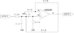
图2为本发明的一种实施方式滤波电路原理图;Fig. 2 is a schematic diagram of a filtering circuit of an embodiment of the present invention;
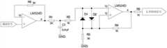
图3为本发明的一种实施方式放大电路原理图;Fig. 3 is a schematic diagram of an amplifying circuit of an embodiment of the present invention;
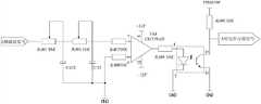
图4为本发明的一种实施方式过零检测电路原理图;Fig. 4 is a schematic diagram of a zero-crossing detection circuit in an embodiment of the present invention;
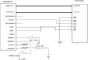
图5为本发明的一种实施方式跳合闸回路的结构图;Fig. 5 is a structural diagram of a tripping circuit of an embodiment of the present invention;
图6为本发明的一种实施方式数据存储器的电路原理图;FIG. 6 is a schematic circuit diagram of a data storage device according to an embodiment of the present invention;
图7为本发明的一种实施方式液晶显示器的电路原理图;FIG. 7 is a schematic circuit diagram of a liquid crystal display in an embodiment of the present invention;
图8为本发明的一种实施方式通讯模块的电路原理图;FIG. 8 is a schematic circuit diagram of a communication module in an embodiment of the present invention;
图9为本发明的一种实施方式蓄电池储能装置的电路原理图;Fig. 9 is a schematic circuit diagram of a battery energy storage device according to an embodiment of the present invention;
图10为本发明的一种实施方式储能单元控制器结构图;Fig. 10 is a structural diagram of an energy storage unit controller according to an embodiment of the present invention;
图11为本发明的一种实施方式蓄电池充电控制方法流程图;Fig. 11 is a flow chart of a storage battery charging control method according to an embodiment of the present invention;
图12为本发明的一种实施方式恒压充电法流程图;Fig. 12 is a flowchart of a constant voltage charging method according to an embodiment of the present invention;
图13为本发明的一种实施方式浮充充电法流程图;Fig. 13 is a flow chart of a float charging method according to an embodiment of the present invention;
图14为本发明的一种实施方式过电流保护方法、过电压保护方法、过欠频保护方法的流程图;Fig. 14 is a flowchart of an overcurrent protection method, an overvoltage protection method, and an over-underfrequency protection method according to an embodiment of the present invention;
图15为本发明的一种实施方式过电流保护方法流程图;FIG. 15 is a flowchart of an overcurrent protection method according to an embodiment of the present invention;
图16为本发明的一种实施方式过电压保护方法流程图;FIG. 16 is a flowchart of an overvoltage protection method according to an embodiment of the present invention;
图17为本发明的一种实施方式过欠频保护方法流程图;Fig. 17 is a flowchart of an over-underfrequency protection method according to an embodiment of the present invention;
图18为本发明的一种实施方式黑启动方法流程图。Fig. 18 is a flowchart of a black start method according to an embodiment of the present invention.
具体实施方式Detailed ways
下面结合附图对本发明的实施方式做进一步详细的说明。Embodiments of the present invention will be further described in detail below in conjunction with the accompanying drawings.
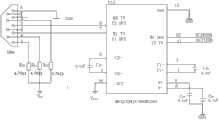
本发明的一种实施方式给出分布式混合供电型智能电网系统的结构图,如图1所示。包括:(1)发电单元:由风力发电机(例如装机容量为3000w)和光伏电池板阵列组成(例如装机容量为3000w),用于为发电系统进行供电。An embodiment of the present invention provides a structural diagram of a distributed hybrid power supply type smart grid system, as shown in FIG. 1 . Including: (1) Power generation unit: composed of a wind generator (for example, with an installed capacity of 3000w) and a photovoltaic panel array (for example, with an installed capacity of 3000w), used to supply power to the power generation system.
(2)直流汇流单元:用于对发电单元1输出的直流电能进行升压处理,本实施方式中采用Boost电路结构(直流升压电路)进行升压,经处理后的直流电能的电压值为24V。(2) DC confluence unit: used to boost the DC power output by the
(3)储能单元:用于储存直流回流单元2输出的直流电能,包括飞轮储能装置、抽水蓄能装置和蓄电池储能装置,上述三个装置使储能单元具有三级储能结构,储能装置的储能优先级依次是:飞轮储能装置、抽水蓄能装置和蓄电池储能装置,从而实现电能利用效率的最优化。另外利用飞轮具有的调频功能,实现对逆变单元4输出电能的频率调节,从而提高逆变其输出电能的质量。(3) Energy storage unit: used to store the DC electric energy output by the
(4)逆变单元:用于将直流汇流单元2输出的直流电能逆变为交流电。逆变单元采用逆变器实现逆变。逆变器利用SVPWM控制算法,产生控制脉冲对逆变器的IGBT的开断频率和时刻进行控制,将直流汇流单元2输出的直流电能逆变成工频为50Hz、幅值为220V的交流电,供给本地交流负载和输送到电网,实现并网发电。(4) Inversion unit: for inverting the DC power outputted by the
(5)并网控制单元:用于对孤岛状态进行检测,并能快速、有效的执行切除并网控制单元的操作,包括并网控制器和电压前置补偿装置。(5) Grid-connected control unit: It is used to detect the island state, and can quickly and effectively execute the operation of removing the grid-connected control unit, including the grid-connected controller and voltage pre-compensation device.
(6)本地交、直流负载:分为:(6) Local AC and DC loads: divided into:
本地直流负载:由系统中的直流用电设备组成;Local DC load: composed of DC electrical equipment in the system;
本地交流负载:由系统中的交流用电设备组成。Local AC Load: Consists of AC consumers in the system.
除上述装置外,本实施方式中还包括保护系统。保护系统包括:电压电流信号采集单元、过电流、过电压、过欠频保护单元和主控单元。In addition to the above devices, this embodiment also includes a protection system. The protection system includes: voltage and current signal acquisition unit, overcurrent, overvoltage, over-underfrequency protection unit and main control unit.
其中,(7)电压、电流信号采集单元:由电压互感器和电流互感器组成,用于采集系统运行的电压、电流信号,经过信号调制电路的处理,将信号转换为幅值为3.3V可供主控单元处理的电信号。Among them, (7) voltage and current signal acquisition unit: composed of voltage transformer and current transformer, used to collect the voltage and current signal of the system operation, after processing by the signal modulation circuit, the signal is converted into a signal with an amplitude of 3.3V. Electrical signal for processing by the main control unit.
(8)过电流、过电压、过欠频保护单元:用于监视系统的运行状态,对系统的异常和事故做出快速反应,保护系统安全,本实施方式,利用跳合闸回路中的继电器实现上述功能,所述的跳合闸回路包括光电耦合器及继电器,所述的继电器还包括:过电压保护继电器、过电流保护继电器、过欠频保护继电器。(8) Overcurrent, overvoltage, over-underfrequency protection unit: used to monitor the operating status of the system, respond quickly to system abnormalities and accidents, and protect the safety of the system. In this embodiment, the relay in the tripping and closing circuit is used To achieve the above functions, the tripping and closing circuit includes a photocoupler and a relay, and the relay also includes: an overvoltage protection relay, an overcurrent protection relay, and an over-underfrequency protection relay.
(9)主控单元:用于对电压、电流信号采集单元7采集的电信号进行运算和判断,向各部分功能单元(如并网控制单元、储能单元、逆变单元、通讯单元、数据存储器、液晶显示)发出控制信号。此外对系统的运行状态的异常数据(异常数据是指系统非正常状态运行的电压、电流和频率的数值,如孤岛状态的数据、系统短路状况下的数据)进行储存和液晶显示,特殊情况(指系统发生故障)下通过通讯单元与上位机进行远程通讯。(9) Main control unit: used for calculating and judging the electrical signals collected by the voltage and current
本发明的实施方式中构建分布式混合供电型智能电网系统如下:In the embodiment of the present invention, the distributed hybrid power supply type smart grid system is constructed as follows:
本实施方式中,采用的风力发电机的型号是SKYWING1000W,光伏电池的型号是SN-150W-单晶;蓄电池的型号是24V/2-10PZS180-1400AH,恒充电压14.8V,浮充电压是13.6V;抽水蓄能装置的电机选用的是1000W的三相凸极同步电机;逆变单元中的逆变器装机型号为FGY-880,储能单元控制器的PLC的型号是西门子S7-200;直流电压互感器的型号为BLZ-1K;直流电流互感器的型号为CT-PTA;三相交流电流互感器的型号为TR1102-2C/5A3.53V;三相交流电压互感器的型号为TV52-100V/3.53V;光电耦合器的型号是TLP521-1;过电压保护继电器的型号是DJ-131;过电流保护继电器的型号是DJ-122;过欠频保护继电器的型号是S2FMR1;主控单元采用的DSP芯片的型号是TMS320F2812,单片机的型号是Atmel89C51;数据存储器的型号为CY7C1041BV;液晶显示器的型号为LCM12864ZK。In this embodiment, the model of the wind power generator used is SKYWING1000W, the model of the photovoltaic battery is SN-150W-single crystal; V; the motor of the pumped storage device is a 1000W three-phase salient pole synchronous motor; the installed model of the inverter in the inverter unit is FGY-880, and the PLC model of the energy storage unit controller is Siemens S7-200; The model of the DC voltage transformer is BLZ-1K; the model of the DC current transformer is CT-PTA; the model of the three-phase AC current transformer is TR1102-2C/5A3.53V; the model of the three-phase AC voltage transformer is TV52- 100V/3.53V; the model of optocoupler is TLP521-1; the model of overvoltage protection relay is DJ-131; the model of overcurrent protection relay is DJ-122; the model of over and under frequency protection relay is S2FMR1; The model of the DSP chip used is TMS320F2812, the model of the one-chip computer is Atmel89C51; the model of the data memory is CY7C1041BV; the model of the liquid crystal display is LCM12864ZK.
具体的电路连接如下:The specific circuit connection is as follows:
本实施方式构建的分布式混合供电型智能电网系统,利用3个直流电流互感器(包括CT1、CT2和CT3)和3个直流电压互感器(包括PT1、PT2和PT3)采集系统的直流电压和直流电流值。其中,PT1、PT2、CT1和CT2设置在发电单元1与直流汇流单元2之间,用于采集发电单元1的输出端的直流电压和直流电流值。PT3和CT3设置在直流汇流单元2与逆变单元4之间,用于采集直流汇流单元2的输出端的直流电压值和直流电流值。The distributed hybrid power supply smart grid system constructed in this embodiment uses three DC current transformers (including CT1, CT2 and CT3) and three DC voltage transformers (including PT1, PT2 and PT3) to collect the DC voltage and DC current value. Wherein, PT1 , PT2 , CT1 and CT2 are arranged between the
利用3个交流电流互感器(包括CT4、CT5和CT6)和3个交流电压互感器(包括PT4、PT5和PT6)采集系统的交流电压和交流电流值,CT4、CT5、CT6、PT4、PT5和PT6设置在逆变单元4与并网控制单元5之间,用于采集逆变器4输出端的交流电流和交流电压值。
上述互感器采集到的信号送入信号调制电路进行滤波、放大处理后,转换为幅值3.3V的电信号。本实施方式中的信号调理电路由滤波电路、放大电路和过零检测电路组成,如图2、图3和图4所示。互感器的输出端连接滤波电路的采样信号端,滤波信号(由于三相电是同频的,因此只需测量一相电压的频率即可,例如A相的电压信号)分为2路:一路经放大电路转换为幅值3.3V的电信号,送入DSP的A/D转换器进行模数转换,另一路通过同步信号的过零检测电路转换为方波信号,送入DSP的计数器,用于测量逆变电能的频率。The signal collected by the transformer is sent to the signal modulation circuit for filtering and amplification processing, and then converted into an electrical signal with an amplitude of 3.3V. The signal conditioning circuit in this embodiment is composed of a filter circuit, an amplification circuit and a zero-crossing detection circuit, as shown in FIG. 2 , FIG. 3 and FIG. 4 . The output terminal of the transformer is connected to the sampling signal terminal of the filter circuit, and the filtered signal (since the three-phase electricity is of the same frequency, it is only necessary to measure the frequency of one phase voltage, such as the voltage signal of phase A) is divided into two channels: one channel It is converted into an electrical signal with an amplitude of 3.3V by the amplifying circuit, sent to the A/D converter of the DSP for analog-to-digital conversion, and the other channel is converted into a square wave signal through the zero-crossing detection circuit of the synchronous signal, and sent to the counter of the DSP for use It is used to measure the frequency of inverter electric energy.
信号调制电路的输出端依次连接DSP的ADCINA0引脚~ADCINA7引脚、ADCINB0引脚~ADCINA3引脚,单片机的P3.0引脚连接DSP的SCITXDA引脚,单片机的P3.1引脚连接DSP的SCIRXDA引脚,单片机的P1.0引脚~P1.7引脚、P2.0引脚依次与9路并联的光电耦合器连接,光电耦合器的输出端依次连接继电器,继电器输出的跳合闸信号施加到相应位置的断路器上,控制断路器(QF1~QF6)的关断,如图5所示。The output terminal of the signal modulation circuit is connected to the ADCINA0 pin ~ ADCINA7 pin and ADCINB0 pin ~ ADCINA3 pin of the DSP in turn, the P3. The SCIRXDA pin, the P1.0 pin ~ P1.7 pin, and the P2.0 pin of the microcontroller are connected to 9 parallel photocouplers in turn, and the output terminals of the photocoupler are connected to the relay in turn, and the tripping and closing of the relay output The signal is applied to the circuit breaker at the corresponding position to control the shutdown of the circuit breaker (QF1~QF6), as shown in Figure 5.
数据存储器的DO引脚~D15引脚依次连接DSP的XD0引脚~XD15引脚,A0引脚~A17引脚依次连接DSP的XA0引脚~XA17引脚,如图6所示。The DO pins to D15 pins of the data memory are connected to the XD0 pins to XD15 pins of the DSP in turn, and the A0 pins to A17 pins are connected to the XA0 pins to XA17 pins of the DSP in turn, as shown in Figure 6.
液晶显示器的RS引脚连接DSP的IOPF4引脚,液晶显示器的R/W引脚连接DSP的IOPF5引脚,液晶显示器的E引脚连接DSP的IOPF6引脚,液晶显示器的D0~D7引脚连接DSP的IOPB1~IOPB7引脚,液晶显示器的/RST引脚连接DSP的IOPC1引脚,如图7所示。The RS pin of the LCD is connected to the IOPF4 pin of the DSP, the R/W pin of the LCD is connected to the IOPF5 pin of the DSP, the E pin of the LCD is connected to the IOPF6 pin of the DSP, and the D0~D7 pins of the LCD are connected to The IOPB1-IOPB7 pins of the DSP, and the /RST pin of the liquid crystal display are connected to the IOPC1 pin of the DSP, as shown in Figure 7.
通讯单元采用MAX232驱动芯片,其R1OUT引脚和T1IN引脚依次连接DSP的SCIRXDB引脚和SCITXDB引脚,如图8所示。The communication unit uses the MAX232 driver chip, and its R1OUT pin and T1IN pin are connected to the SCIRXDB pin and the SCITXDB pin of the DSP in turn, as shown in Figure 8.
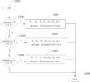
本实施方式中的蓄电池储能装置如图9所示。该装置包括三层结构,第一层结构由3个蓄电池组构成,分别为蓄电池组A、蓄电池组B和蓄电池组C。蓄电池组A或B或C均由并联的11个蓄电池组成,且以蓄电池组A为开头,以蓄电池组C为结尾横向排列。蓄电池组A的正极输入端连接蓄电池组C的正极输出端,蓄电池组A的负极输入端连接蓄电池组C的负极输出端,且在其连接导线上设置有开关Kc4,蓄电池组A的正极输出端连接蓄电池组B的正极输入端,蓄电池组A的负极输出端连接蓄电池组B的负极输入端,且在其连接导线上设置有开关Ka4,蓄电池组B的正极输出端连接蓄电池组C的正极输入端,蓄电池组B的负极输出端连接蓄电池组C的负极输入端,且在其连接导线上设置有开关Kb4。The battery energy storage device in this embodiment is shown in FIG. 9 . The device includes a three-layer structure, and the first layer structure is composed of three battery packs, namely battery pack A, battery pack B and battery pack C. Battery pack A or B or C is composed of 11 batteries connected in parallel, starting with battery pack A and ending with battery pack C in a horizontal arrangement. The positive input end of the battery pack A is connected to the positive output end of the battery pack C, the negative input end of the battery pack A is connected to the negative output end of the battery pack C, and a switch Kc4 is set on the connecting wire, and the positive output end of the battery pack A The terminal is connected to the positive input terminal of battery pack B, the negative output terminal of battery pack A is connected to the negative input terminal of battery pack B, and a switch Ka4 is set on the connecting wire, and the positive output terminal of battery pack B is connected to the negative terminal of battery pack C. The positive input terminal and the negative output terminal of battery pack B are connected to the negative input terminal of battery pack C, and a switch Kb4 is provided on the connecting wire.
在第二层结构,也由3个蓄电池组构成,分别为蓄电池组D、蓄电池组E和蓄电池组F。蓄电池组D或E或F均由并联的12个蓄电池组成,且以蓄电池组D开头,以蓄电池组F为结尾横向排列。蓄电池组D的负极输入端连接充电电源的负极,在其连接导线上设置有开关Ka1,蓄电池组E的负极输入端连接充电电源的负极,在其连接导线上设置有开关Kb1,蓄电池组F的正极输入端连接充电电源的正极,且在其连接导线上设置有开关Kc1。蓄电池组D的正极输出端连接第一层中蓄电池组A的正极输入端,蓄电池组D的负极输出端连接第一层中蓄电池组A的负极输入端,且在其连接导线上设置有开关Ka3,蓄电池组E的正极输出端连接第一层中蓄电池组B的正极输入端,蓄电池组E的负极输出端连接第一层中蓄电池组B的负极输入端,且在其连接导线上设置有开关Kb3,蓄电池组F的正极输出端连接第一层中蓄电池组C的正极输入端,蓄电池组F的负极输出端连接第一层中蓄电池组C的负极输入端,且在其连接导线上设置有开关Kc3。In the second layer structure, it is also composed of three battery packs, namely battery pack D, battery pack E and battery pack F. Battery pack D or E or F is composed of 12 batteries connected in parallel, starting with battery pack D and ending with battery pack F in a horizontal arrangement. The negative input terminal of battery pack D is connected to the negative pole of the charging power supply, and a switch Ka1 is set on its connecting wire. The negative input end of battery pack E is connected to the negative pole of the charging power supply, and a switch Kb1 is set on its connecting wire. The positive input end of F is connected to the positive pole of the charging power supply, and a switch Kc1 is set on its connecting wire. The positive output end of battery pack D is connected to the positive input end of battery pack A in the first layer, the negative output end of battery pack D is connected to the negative input end of battery pack A in the first layer, and a switch K is arranged on the connecting wirea3 , the positive output terminal of battery pack E is connected to the positive input terminal of battery pack B in the first layer, the negative output terminal of battery pack E is connected to the negative input terminal of battery pack B in the first layer, and the connecting wire is provided with Switch Kb3 , the positive output end of battery pack F is connected to the positive input end of battery pack C in the first layer, the negative output end of battery pack F is connected to the negative input end of battery pack C in the first layer, and on its connecting wire A switch Kc3 is provided.
在第三层结构,由蓄电池组G构成,其中,蓄电池组G由并联的3个蓄电池组成。蓄电池组G的正极输入端连接充电电源的正极,蓄电池组G的负极输入端连接充电电源的负极,蓄电池组G的负极输入端依次连接第二层中蓄电池组的负极输入端,且在干路导线上设置一个总开关K2,蓄电池组G的正极输入端依次连接第二层中蓄电池组的正极输入端,且在干路导线上设置一个总开关K1,且在D组蓄电池支路导线上设置有开关Ka2,E组蓄电池支路导线上设置有开关Kb2,F组蓄电池支路导线上设置有开关Kc2。蓄电池组G的负极输出端连接蓄电池组D的负极输入端,蓄电池组G的正极输出端连接蓄电池组D的正极输入端,且在连接导线上设置有开关Ka2,蓄电池组G的负极输出端连接蓄电池组E的负极输入端,蓄电池组G的正极输出端连接蓄电池组E的正极输入端,且在连接导线上设置有开关Kb2,蓄电池组G的负极输出端连接蓄电池组F的负极输入端,蓄电池组G的正极输出端连接蓄电池组F的正极输入端,且在连接导线上设置有开关Kc2。In the third layer structure, it is composed of battery pack G, wherein the battery pack G is composed of 3 batteries connected in parallel. The positive input terminal of the battery pack G is connected to the positive pole of the charging power supply, the negative input terminal of the battery pack G is connected to the negative pole of the charging power supply, the negative input terminal of the battery pack G is connected to the negative input terminal of the battery pack in the second layer in turn, and the main circuit A main switch K2 is set on the wire, the positive input end of the battery pack G is connected to the positive input end of the battery pack in the second layer in turn, and a main switch K1 is set on the main wire, and the battery branch wire of the D group A switch Ka2 is set on the switch K a2 , a switch Kb2 is set on the battery branch wire of the E group, and a switch Kc2 is set on the F group battery branch wire. The negative output terminal of the storage battery G is connected to the negative input terminal of the storage battery D, the positive output terminal of the storage battery G is connected to the positive input terminal of the storage battery D, and a switch Ka2 is arranged on the connecting wire, and the negative output terminal of the storage battery G Connect the negative input end of the battery pack E, the positive output end of the battery pack G is connected to the positive input end of the battery pack E, and a switch Kb2 is set on the connecting wire, the negative output end of the battery pack G is connected to the negative input end of the battery pack F terminal, the positive output end of battery pack G is connected to the positive input end of battery pack F, and a switch Kc2 is set on the connecting lead.
实现分布式混合供电型智能电网系统的控制方法,,包括蓄电池充电控制方法、过电流过过电压欠频保护方法及黑启动方法。A control method for realizing a distributed hybrid power supply type smart grid system includes a storage battery charging control method, an overcurrent, overvoltage, and underfrequency protection method, and a black start method.
其中,所述的蓄电池充电控制方法,如图11所示。该流程开始于1101。在步骤1102,电压互感器采集蓄电池储能装置的电压信息,具体是指图9中的采样端1到采样端6的电压信息。Wherein, the battery charging control method is shown in FIG. 11 . The process starts at 1101. In
在步骤1103,采集的电压信息通过信号调制电路转换为幅值为3.3V的电信号,送入DSP的A/D转化器进行A/D转换,记录每一个采样端的电压值,并保存到数据储存器中。In
在步骤1104,DSP将A/D转换后的电压值传输到单片机中。In
在步骤1105,采样端的电压值与13.6V进行比较,若采样端的电压值大于13.6V,则采用恒压法对蓄电池组进行充电,执行步骤1106;若采样端的电压值小于13.6V,则采用浮充法对蓄电池组进行充电,执行步骤1107。In
在步骤1106,采用恒压法对蓄电池组进行充电,其流程如图12所示。该流程开始于步骤1201。在步骤1202,判断采样端1或采样端4的电压是否大于13.6V,若是,则单片机发出PWM波驱动蓄电池组控制器,执行步骤1203;若否,则执行步骤1204。In
在步骤1203,蓄电池组控制器内PLC发出信号,使开关Ka1、Ka3、K1、Kb2、Kb3、Kb4闭合其他开关断开,实现对蓄电池组A、蓄电池组D的恒压充电,执行步骤1208。In
在步骤1204,判断采样端2或采样端5的电压是否大于13.6V,若是,则单片机发出PWM波驱动蓄电池组控制器,执行步骤1205;若否,则执行步骤1206;In
在步骤1205,蓄电池组控制器内PLC发出信号,使开关Kb1、Kb3、K2、Kc2、Kc3、Kc4闭合,其他开关断开,实现对蓄电池组B、蓄电池组E的恒压充电,执行步骤1208。In
在步骤1206,判断采样端3或采样端6的电压是否大于13.6V,若是,则单片机发出PWM波驱动蓄电池组控制器,执行步骤1207,否则,执行步骤1208。In
在步骤1207,蓄电池组控制器内PLC发出信号,使开关Kc1、Kc3、K1、Ka2、Ka3、Ka4闭合,其他开关断开,实现对C、F组蓄电池进行恒压充电。In
在步骤1208,结束恒压充电。In
在步骤1107,采用浮充法对蓄电池组进行充电,流程如图13所示。该流程开始于步骤1301。在步骤1302,判断采样端1或4端电压是否小于13.6V,若是,则单片机发出PWM波驱动蓄电池组控制器,执行步骤1303;若否,则执行步骤1304。In
在步骤1303,蓄电池组控制器内PLC发出信号,使开关K1、Ka2、Ka3、Kb1、Kb3、Kb4闭合,其他开关断开,实现对蓄电池组A、蓄电池组D和蓄电池组G进行浮充充电,执行步骤1308。In step 1303, the PLC in the battery pack controller sends a signal to close the switches K1 , Ka2 , Ka3 , Kb1 , Kb3 , and Kb4 , and open the other switches, so that battery pack A, battery pack D, and battery pack Group G performs float charging, and executes step 1308 .
在步骤1304,判断采样端2或采样端5的电压是否小于13.6V,若是,则单片机发出PWM波驱动蓄电池组控制器,执行步骤1305;若否,则执行步骤1306。In step 1304, it is judged whether the voltage of the
在步骤1305,蓄电池组控制器内PLC发出信号,使开关K1、Kb2、Kb3、Kc1、Kc3、Kc4闭合其他断开,实现对蓄电池组B、蓄电池组E和蓄电池组G蓄电池进行浮充充电,执行步骤1308。In step 1305, the PLC in the battery pack controller sends out a signal to make the switches K1 , Kb2 , Kb3 , Kc1 , Kc3 , and Kc4 closed and other switches off, so as to realize the control of battery pack B, battery pack E, and battery pack G. The storage battery performs float charging, and step 1308 is executed.
在步骤1306,判断采样端3或采样端6的电压是否小于13.6V,若是,则单片机发出PWM波驱动蓄电池组控制器,执行步骤1307;若否,则执行步骤1308。In step 1306, it is judged whether the voltage of sampling terminal 3 or
在步骤1307,则单片机发出PWM波驱动蓄电池组控制器,蓄电池组控制器内PLC发出信号,使开关K2、Kc2、Kc3、Ka1、Ka3、Ka4闭合其他断开,此时可实现对蓄电池组C、蓄电池组F和蓄电池组G进行浮充充电。In step 1307, the single-chip microcomputer sends a PWM wave to drive the battery pack controller, and the PLC in the battery pack controller sends a signal to make the switches K2 , Kc2 , Kc3 , Ka1 , Ka3 , and Ka4 close and the others are off. Float charging can be realized for battery pack C, battery pack F and battery pack G.
在步骤1308,结束浮充充电。In step 1308, the float charging is ended.
在步骤1108,结束蓄电池组充电方法。At
过电流过欠频过电压保护方法的流程如图14所示,该流程开始于1401。在步骤1402,输入保护系统的整定值,其中,过电流的整定值范围为0~50A,过流延时0.1~20s,步进:0.1s;过电压的整定值范围为0~200V,欠压延时为0.1~20s,步进:0.1s;过欠频整定值范围为39.1~49.5Hz,延时定值整定范围为0~99.9s,整定级差为0.1s。The flow of the over-current, over-under-frequency and over-voltage protection method is shown in FIG. 14 , and the flow starts at
在步骤1403,系统中的电压互感器采集电压信号、电流互感器采集电流信号。In
在步骤1404,互感器采集的信号送入信号调制电路转换为幅值3.3V的电信号。In
在步骤1405,将逆变器输出端的(A相或B相或C相)电压信号送入同步信号的过零检测电路,将(A相或B相或C相)电压正弦波转换为幅值3.3V的方波信号。In
在步骤1406,转换后的信号送入DSP的A/D转换器进行A/D转换,其中,(A或B或C)相电压的方波信号送入DSP的计数单元,测量逆变电能的频率,并将转换和测量的数据存入数据存储器。In
在步骤1407,DSP将采样得到的系统运行的电压、电流、频率信号通过液晶显示器显示。In
在步骤1408,将DSP储存的数据通过串口传输到单片机中。In
在步骤1409,进行过电流保护、过电压保护和过欠频保护。所述的过电流保护,如图15所示,该流程开始于1501。在步骤1502,单片机对接收到的数据进行处理。In
在步骤1503,判断采集到的数据是否在过电流保护整定值的围内,若是,则执行步骤1504,若否,则不进行操作,执行步骤1505;In
在步骤1504,单片机发出的信号,通过光电耦合器后加在继电器上,控制断路器跳闸,完成继电保护;In
在步骤1505,结束。In
过电压保护,如图16所示。该流程开始于步骤1601。在步骤1602,单片机对接收到数据进行处理;overvoltage protection, as shown in Figure 16. The process starts at
在步骤1603,判断采集到的数据是否在过电压保护整定值范围内,若是,则执行步骤1604;若否,则不进任何操作,执行步骤1605;In
在步骤1604,单片机发出的信号通过光电耦合器后加在继电器上,控制断路器跳闸,完成继电保护;In
在步骤1605,结束。In
过欠频保护流程如图17所示。该流程开始于步骤1701。在步骤1702,一个采样周期后,单片机对新的采样数据数据进行处理。Figure 17 shows the process of over- and under-frequency protection. The process starts at
在步骤1703:判断采集到的数据是否在过欠频保护整定值的范围内,若是,则执行步骤1704;若否,则执行步骤1707。In step 1703: determine whether the collected data is within the range of the over-underfrequency protection setting value, if yes, execute
在步骤1704,单片机发出PWM波控制储能单元控制器,使得飞轮储能装置接入系统进行放电,调整并网电能的频率。In
在步骤1705,一个采样周期后,单片机对新的采样数据数据进行处理,判断采集到的数据是否在过欠频保护整定值的围内,若否,则不进行下一步动作,执行步骤1707,若是,则执行步骤1706。In
在步骤1706,数据处理单片机发出的信号通过光电耦合器后加在继电器上,控制断路器断开,完成继电保护。In
在步骤1707,结束。In
在步骤1410,单片机将各继电器的状态通过串口传输到DSP中。In
在步骤1411,判断继电器的状态是否发生了变化,若没发生变化,则执行步骤1413,否则,执行步骤1412。In
在步骤1412,DSP通过通讯模块与上位机进行远程通讯,告知调度人员系统的故障状态和相关的故障状态参数。In
在步骤1413,继电器状态参数,通过液晶显示电路进行状态显示。In
在步骤1414,结束过电流过欠频过电压保护方法。In
本实施方式中的黑启动方法流程图,如图18所示。该方法开始于1801。在步骤1802,确定系统的黑启动电源。当风速大于5m/s时,选取发电单元(1)中的风力发电机(如500W)作为黑启动电源;当光照强度大于200lux时,选取发电单元中的光伏电池板(如1000W)作为黑启动电源;如果上述条件均不能满足,则不能进行黑启动。The flow chart of the black start method in this embodiment is shown in FIG. 18 . The method started in 1801. At step 1802, the black start power of the system is determined. When the wind speed is greater than 5m/s, select the wind generator (such as 500W) in the power generation unit (1) as the black start power supply; when the light intensity is greater than 200lux, select the photovoltaic panel (such as 1000W) in the power generation unit as the black start Power supply; if none of the above conditions are met, black start cannot be performed.
在步骤1803,黑启动电源向主控单元(9)的DSP和单片机供电。In step 1803, the black start power supplies power to the DSP and single-chip microcomputer of the main control unit (9).
在步骤1804,判断DSP和单片机的工作状态是否正常,若正常,则执行步骤1805,否则;执行步骤1813。In step 1804, it is judged whether the working status of the DSP and the single-chip microcomputer is normal, if normal, then execute step 1805, otherwise; execute step 1813.
在步骤1805,首先启动Boost和储能单元,黑启动电源向分布式混合供电型智能电网系统输出电能。In step 1805, the Boost and the energy storage unit are first started, and the black start power supply outputs electric energy to the distributed hybrid power supply smart grid system.
在步骤1806,时刻监控黑启动电源的电压值,判断该电压值是否超出规定范围,若是,则执行第1807;若否,则执行步骤1808。In step 1806, the voltage value of the black start power supply is constantly monitored, and it is judged whether the voltage value exceeds the specified range, if yes, execute step 1807; if not, execute step 1808.
在步骤1807,启动剩余的风力发电机和光伏电池板,维持黑启动电源的电压值稳定在规定的范围之内。In step 1807, the remaining wind generators and photovoltaic panels are started, and the voltage value of the black start power supply is kept stable within a specified range.
在步骤1808,启动逆变单元,对输出的直流电能进行逆变,并执行过流欠频欠电压保护方法监控系统的安全状态。In step 1808, start the inverter unit to invert the output DC power, and execute the over-current, under-frequency and under-voltage protection method to monitor the safety state of the system.
在步骤1809,判断系统安全状态是否符合要求,若符合,则执行步骤1811;否则,执行步骤1810。In step 1809, it is judged whether the security state of the system meets the requirement, if yes, then execute step 1811; otherwise, execute step 1810.
在步骤1810,通过控制储能单元,对各互感器(CT1~CT6及PT1~PT6)采集点的电压、电流和逆变电能的频率进行调节,执行步骤1811。In step 1810, by controlling the energy storage unit, the voltage, current and frequency of the inverter electric energy at the collection points of each transformer (CT1-CT6 and PT1-PT6) are adjusted, and step 1811 is executed.
在步骤1811,对本地直流负载和交流负载进行供电。In step 1811, power is supplied to local DC loads and AC loads.
在步骤1812,启动并网控制单元,使得分布式混合供电型智能电网系统与电网连接,实现系统并网输电,执行步骤1814。In step 1812, the grid-connected control unit is started, so that the distributed hybrid power supply type smart grid system is connected to the grid, and the grid-connected power transmission of the system is realized, and step 1814 is executed.
在步骤1813,黑启动电源停止供电,分布式混合供电型智能电网系统进行全面检修。In step 1813, the black start power supply stops supplying power, and the distributed hybrid power supply type smart grid system conducts overall maintenance.
在步骤1814,结束黑启动控制。In step 1814, black start control ends.
虽然以上描述了本发明的具体实施方式,但是本领域内的熟练技术人员应当理解,这些仅仅是举例说明,本领域技术人员可由这些实施方式做出多种变更或修改,而不背离本发明的原理和实质。本发明的范围仅由所附权利要求书限定。Although the specific embodiments of the present invention have been described above, those skilled in the art should understand that these are only examples, and those skilled in the art can make various changes or modifications from these embodiments without departing from the principles of the present invention. principle and substance. The scope of the invention is limited only by the appended claims.
Claims (5)
Priority Applications (2)
| Application Number | Priority Date | Filing Date | Title |
|---|---|---|---|
| CN201210094291.6ACN102624018B (en) | 2012-03-31 | 2012-03-31 | Distributed hybrid power supply type smart grid system and control method |
| EP12180853.9AEP2645522B1 (en) | 2012-03-31 | 2012-08-17 | A battery storage device for distributed hybrid powered smart grid system and control method thereof |
Applications Claiming Priority (1)
| Application Number | Priority Date | Filing Date | Title |
|---|---|---|---|
| CN201210094291.6ACN102624018B (en) | 2012-03-31 | 2012-03-31 | Distributed hybrid power supply type smart grid system and control method |
Publications (2)
| Publication Number | Publication Date |
|---|---|
| CN102624018A CN102624018A (en) | 2012-08-01 |
| CN102624018Btrue CN102624018B (en) | 2014-05-14 |
Family
ID=46563760
Family Applications (1)
| Application Number | Title | Priority Date | Filing Date |
|---|---|---|---|
| CN201210094291.6AExpired - Fee RelatedCN102624018B (en) | 2012-03-31 | 2012-03-31 | Distributed hybrid power supply type smart grid system and control method |
Country Status (2)
| Country | Link |
|---|---|
| EP (1) | EP2645522B1 (en) |
| CN (1) | CN102624018B (en) |
Families Citing this family (28)
| Publication number | Priority date | Publication date | Assignee | Title |
|---|---|---|---|---|
| CN103001247B (en)* | 2012-11-13 | 2014-09-10 | 中国电力科学研究院 | Off-network-type microgrid black-start method |
| CN103259287B (en)* | 2013-05-10 | 2014-12-31 | 东北大学 | Bidirectional grid-connected inversion device and method of distributed new energy power generation system |
| CN103323711B (en)* | 2013-06-09 | 2015-07-29 | 东北大学 | A kind of low-pressure grid-connection pick-up unit of distributed new electricity generation system and method |
| US9917447B2 (en) | 2014-03-13 | 2018-03-13 | Enphase Energy, Inc. | Systems and methods for synchronizing an appliance load to a local power generating capability |
| CN103928942B (en)* | 2014-04-18 | 2015-10-28 | 芜湖职业技术学院 | A kind of light storage joint distributed power generation off-grid system black-start method |
| ES2553808B1 (en)* | 2014-06-10 | 2016-06-08 | José Vicente CALATRAVA MARTÍNEZ | Device and procedure for storage, power regulation and delivery of electrical energy at favorable hours telematically controlled |
| CN104113133B (en)* | 2014-07-01 | 2016-10-05 | 广东易事特电源股份有限公司 | Intelligent photovoltaic off-network inverter system and power consumption control method thereof |
| CN104218568A (en)* | 2014-08-14 | 2014-12-17 | 国家电网公司 | Power grid black-start method with participation of regional small hydropower stations and new energy hybrid micro-grids |
| CN104638645B (en)* | 2015-02-12 | 2017-03-08 | 东北大学 | A kind of energy the Internet and its multi-level control system and control method |
| CN106058909A (en)* | 2016-01-13 | 2016-10-26 | 万向钱潮股份有限公司 | On-grid and off-grid energy storage PCS (Power Controlling System) and control method thereof |
| DE102016105662A1 (en)* | 2016-03-29 | 2017-10-05 | Wobben Properties Gmbh | Method for feeding electrical power into an electrical supply network with a wind farm and wind farm |
| DE102016218242A1 (en) | 2016-09-22 | 2018-03-22 | Siemens Aktiengesellschaft | DC overvoltage protection for an energy system |
| CN107785919B (en)* | 2017-09-22 | 2024-05-03 | 中节能工程技术研究院有限公司 | Hybrid energy storage system and control method thereof |
| DE102017127081B4 (en)* | 2017-11-17 | 2019-05-29 | Sma Solar Technology Ag | Method for black start of a power supply device, bidirectional inverter and power supply device with a bidirectional inverter |
| CN109120010A (en)* | 2018-09-21 | 2019-01-01 | 无锡美凯能源科技有限公司 | A kind of alternating current-direct current mixing tandem type micro-capacitance sensor applied to communication base station field |
| CN109546710A (en)* | 2018-12-28 | 2019-03-29 | 苏州工业园区和顺电气股份有限公司 | High-power intelligent quick charger |
| CN110481379B (en)* | 2019-05-15 | 2024-03-12 | 苏州工业园区和顺电气股份有限公司 | Stable smart charger |
| CN110242479B (en)* | 2019-06-19 | 2024-02-27 | 浙江中新电力工程建设有限公司自动化分公司 | Distribution network branch line ground fault positioning system |
| CN110259627B (en)* | 2019-06-19 | 2024-02-27 | 浙江中新电力工程建设有限公司自动化分公司 | Electric power construction safety management system based on electric power internet of things |
| EP4018522A1 (en)* | 2019-08-21 | 2022-06-29 | General Electric Company | Power grid restoration system |
| CN111273721B (en)* | 2020-03-25 | 2025-01-07 | 福建福大北斗通信科技有限公司 | An efficient control system and method based on four-segment linear zero-delay blind-zone converter |
| CN111416425A (en)* | 2020-03-31 | 2020-07-14 | 阜阳师范大学 | An artificial intelligence-based project site management system and method |
| CN112542851B (en)* | 2020-11-23 | 2023-05-30 | 南方电网调峰调频发电有限公司 | Black start circuit of electric wire netting and charge-discharge stake |
| CN112952875B (en)* | 2021-01-26 | 2023-05-05 | 广东电网有限责任公司 | Protection method, device, equipment and storage medium for user side battery energy storage system |
| US11489363B2 (en) | 2021-02-24 | 2022-11-01 | General Electric Company | System and method for black starting power plant |
| SE545369C2 (en)* | 2021-10-05 | 2023-07-18 | Bram Energy Store Ab | Power booster in off-grid |
| CN118117607A (en)* | 2024-02-02 | 2024-05-31 | 太一新能源(徐州)有限公司 | New energy power generation grid load fluctuation compensation method and system |
| CN119315624B (en)* | 2024-10-28 | 2025-09-30 | 国网江苏省电力有限公司徐州市铜山区供电分公司 | A photovoltaic new energy on-grid and off-grid control circuit |
Family Cites Families (4)
| Publication number | Priority date | Publication date | Assignee | Title |
|---|---|---|---|---|
| JP2005245183A (en)* | 2004-02-27 | 2005-09-08 | Mitsubishi Heavy Ind Ltd | Power storage device, hybrid power supply and hybrid power supply system |
| JP2005312138A (en)* | 2004-04-19 | 2005-11-04 | Canon Inc | Power controller, power generation system and power system |
| US20080218127A1 (en)* | 2007-03-07 | 2008-09-11 | O2Micro Inc. | Battery management systems with controllable adapter output |
| DE102008000560A1 (en)* | 2008-03-07 | 2009-09-10 | Dilo Trading Ag | Mains-independent electrical energy storage unit |
- 2012
- 2012-03-31CNCN201210094291.6Apatent/CN102624018B/ennot_activeExpired - Fee Related
- 2012-08-17EPEP12180853.9Apatent/EP2645522B1/ennot_activeNot-in-force
Also Published As
| Publication number | Publication date |
|---|---|
| EP2645522B1 (en) | 2014-11-26 |
| CN102624018A (en) | 2012-08-01 |
| EP2645522A1 (en) | 2013-10-02 |
Similar Documents
| Publication | Publication Date | Title |
|---|---|---|
| CN102624018B (en) | Distributed hybrid power supply type smart grid system and control method | |
| Cvetkovic et al. | Future home uninterruptible renewable energy system with vehicle-to-grid technology | |
| CN103337869B (en) | A kind of method of novel battery energy-storage system and function integration design thereof | |
| CN103595138B (en) | A kind of smart micro-grid system | |
| CN104281977B (en) | A kind of mixed type micro-capacitance sensor application platform and its control method | |
| CN111404186B (en) | Distribution transformer dynamic capacity-increasing intelligent energy storage device and control method | |
| CN102412598B (en) | Minitype intelligent bidirectional self-adaptation grid-connected photovoltaic power generation system and control method thereof | |
| CN102969731B (en) | A kind of distribution type photovoltaic energy storage system | |
| CN203481919U (en) | Microgrid experimental platform capable of being automatically and seamlessly switched between grid-connected mode and grid-isolated mode | |
| CN110011344B (en) | Energy storage system and control method thereof | |
| CN102651553A (en) | Energy storage adjusting system for wind power field | |
| CN108347067B (en) | Micro-grid architecture containing battery energy storage and generator and control method | |
| CN114709867A (en) | A distributed energy grid-connected flexible consumption system based on intelligent fusion terminal | |
| CN104901326A (en) | Control rod drive mechanism static power supply system and energy storage system and power supply method thereof | |
| CN103199594B (en) | Wind and light storage type electric vehicle charging and replacing power station | |
| CN101728835A (en) | Battery power energy storing device for smoothing output power of wind power generation | |
| Martirano et al. | Implementation of SCADA systems for a real microgrid lab testbed | |
| CN202340124U (en) | Small intelligent bidirectional self-adaptive photovoltaic grid-connected power generation system | |
| CN103337886B (en) | Industrial park wind-light storage micro-grid system | |
| CN107230995A (en) | A kind of intelligent substation micro-grid system | |
| CN209860604U (en) | Energy storage system | |
| CN116316565A (en) | Optimization method for substation power-storage-direct microgrid system | |
| CN114825591A (en) | Photovoltaic energy storage and data acquisition system based on PLC control | |
| CN209982088U (en) | Primary topological structure of electrochemical energy storage system based on group-string PCS | |
| CN203180598U (en) | Wind-storage and light-storage typed station for power charging and battery replacing for electric automobiles |
Legal Events
| Date | Code | Title | Description |
|---|---|---|---|
| C06 | Publication | ||
| PB01 | Publication | ||
| C10 | Entry into substantive examination | ||
| SE01 | Entry into force of request for substantive examination | ||
| C14 | Grant of patent or utility model | ||
| GR01 | Patent grant | ||
| CF01 | Termination of patent right due to non-payment of annual fee | Granted publication date:20140514 Termination date:20160331 | |
| CF01 | Termination of patent right due to non-payment of annual fee |