CN102614074A - Compression treatment system - Google Patents
Compression treatment systemDownload PDFInfo
- Publication number
- CN102614074A CN102614074ACN201210098027XACN201210098027ACN102614074ACN 102614074 ACN102614074 ACN 102614074ACN 201210098027X ACN201210098027X ACN 201210098027XACN 201210098027 ACN201210098027 ACN 201210098027ACN 102614074 ACN102614074 ACN 102614074A
- Authority
- CN
- China
- Prior art keywords
- pressure
- therapy system
- compression
- compression therapy
- controller
- Prior art date
- Legal status (The legal status is an assumption and is not a legal conclusion. Google has not performed a legal analysis and makes no representation as to the accuracy of the status listed.)
- Granted
Links
- 230000006835compressionEffects0.000titleclaimsabstractdescription156
- 238000007906compressionMethods0.000titleclaimsabstractdescription156
- 238000002560therapeutic procedureMethods0.000claimsabstractdescription118
- 239000012530fluidSubstances0.000claimsabstractdescription37
- 238000004891communicationMethods0.000claimsabstractdescription17
- 238000012544monitoring processMethods0.000claimsdescription7
- 210000002414legAnatomy0.000description41
- 210000003414extremityAnatomy0.000description34
- 210000002683footAnatomy0.000description29
- 238000005259measurementMethods0.000description25
- 210000000689upper legAnatomy0.000description21
- 244000309466calfSpecies0.000description19
- 230000002792vascularEffects0.000description18
- 238000000034methodMethods0.000description13
- 210000003423ankleAnatomy0.000description12
- 238000012546transferMethods0.000description10
- 238000012360testing methodMethods0.000description9
- 239000008280bloodSubstances0.000description8
- 210000004369bloodAnatomy0.000description8
- 206010051055Deep vein thrombosisDiseases0.000description7
- 206010047249Venous thrombosisDiseases0.000description7
- 238000001514detection methodMethods0.000description7
- 210000003462veinAnatomy0.000description7
- 230000008901benefitEffects0.000description6
- 230000000007visual effectEffects0.000description6
- 210000004712air sacAnatomy0.000description5
- 230000007812deficiencyEffects0.000description5
- 230000000694effectsEffects0.000description5
- 238000004519manufacturing processMethods0.000description5
- 230000013011matingEffects0.000description5
- 230000008569processEffects0.000description5
- 230000033228biological regulationEffects0.000description4
- 238000009530blood pressure measurementMethods0.000description4
- 238000004364calculation methodMethods0.000description4
- 230000007246mechanismEffects0.000description4
- 238000003860storageMethods0.000description4
- 230000017531blood circulationEffects0.000description3
- 238000000554physical therapyMethods0.000description3
- 230000000069prophylactic effectEffects0.000description3
- 238000003466weldingMethods0.000description3
- 206010002091AnaesthesiaDiseases0.000description2
- 206010030124Oedema peripheralDiseases0.000description2
- 230000037005anaesthesiaEffects0.000description2
- 230000035602clottingEffects0.000description2
- 230000003750conditioning effectEffects0.000description2
- 239000000463materialSubstances0.000description2
- 238000012986modificationMethods0.000description2
- 230000004048modificationEffects0.000description2
- 229920000642polymerPolymers0.000description2
- 230000002265preventionEffects0.000description2
- 230000002035prolonged effectEffects0.000description2
- 238000005070samplingMethods0.000description2
- 238000001356surgical procedureMethods0.000description2
- 230000001960triggered effectEffects0.000description2
- 206010053567CoagulopathiesDiseases0.000description1
- 208000005189EmbolismDiseases0.000description1
- HBBGRARXTFLTSG-UHFFFAOYSA-NLithium ionChemical compound[Li+]HBBGRARXTFLTSG-UHFFFAOYSA-N0.000description1
- 206010028980NeoplasmDiseases0.000description1
- 208000008589ObesityDiseases0.000description1
- 239000004743PolypropyleneSubstances0.000description1
- 208000001435ThromboembolismDiseases0.000description1
- 208000027418Wounds and injuryDiseases0.000description1
- 230000004913activationEffects0.000description1
- 239000000853adhesiveSubstances0.000description1
- 230000001070adhesive effectEffects0.000description1
- 230000002411adverseEffects0.000description1
- 230000000712assemblyEffects0.000description1
- 238000000429assemblyMethods0.000description1
- 210000001142backAnatomy0.000description1
- 201000011510cancerDiseases0.000description1
- 230000008859changeEffects0.000description1
- 230000004087circulationEffects0.000description1
- 238000011340continuous therapyMethods0.000description1
- 230000008602contractionEffects0.000description1
- 238000001816coolingMethods0.000description1
- 125000004122cyclic groupChemical group0.000description1
- 230000006378damageEffects0.000description1
- 230000003111delayed effectEffects0.000description1
- 238000013461designMethods0.000description1
- 238000010586diagramMethods0.000description1
- 230000010339dilationEffects0.000description1
- 201000010099diseaseDiseases0.000description1
- 208000037265diseases, disorders, signs and symptomsDiseases0.000description1
- 230000002526effect on cardiovascular systemEffects0.000description1
- 230000007613environmental effectEffects0.000description1
- 239000012634fragmentSubstances0.000description1
- 238000001802infusionMethods0.000description1
- 208000014674injuryDiseases0.000description1
- 210000003127kneeAnatomy0.000description1
- 229910001416lithium ionInorganic materials0.000description1
- 210000003141lower extremityAnatomy0.000description1
- 238000012423maintenanceMethods0.000description1
- 230000007257malfunctionEffects0.000description1
- 230000036210malignancyEffects0.000description1
- 239000012528membraneSubstances0.000description1
- 229910052751metalInorganic materials0.000description1
- 239000002184metalSubstances0.000description1
- 150000002739metalsChemical class0.000description1
- 235000020824obesityNutrition0.000description1
- 230000008520organizationEffects0.000description1
- 210000004197pelvisAnatomy0.000description1
- 230000000737periodic effectEffects0.000description1
- -1polypropylenePolymers0.000description1
- 229920001155polypropylenePolymers0.000description1
- 230000002980postoperative effectEffects0.000description1
- 210000001147pulmonary arteryAnatomy0.000description1
- 230000002685pulmonary effectEffects0.000description1
- 239000012858resilient materialSubstances0.000description1
- 239000002904solventSubstances0.000description1
- 229910001220stainless steelInorganic materials0.000description1
- 239000010935stainless steelSubstances0.000description1
- 230000003068static effectEffects0.000description1
- 238000012956testing procedureMethods0.000description1
Images


Classifications
- A—HUMAN NECESSITIES
- A61—MEDICAL OR VETERINARY SCIENCE; HYGIENE
- A61H—PHYSICAL THERAPY APPARATUS, e.g. DEVICES FOR LOCATING OR STIMULATING REFLEX POINTS IN THE BODY; ARTIFICIAL RESPIRATION; MASSAGE; BATHING DEVICES FOR SPECIAL THERAPEUTIC OR HYGIENIC PURPOSES OR SPECIFIC PARTS OF THE BODY
- A61H23/00—Percussion or vibration massage, e.g. using supersonic vibration; Suction-vibration massage; Massage with moving diaphragms
- A61H23/04—Percussion or vibration massage, e.g. using supersonic vibration; Suction-vibration massage; Massage with moving diaphragms with hydraulic or pneumatic drive
- A—HUMAN NECESSITIES
- A61—MEDICAL OR VETERINARY SCIENCE; HYGIENE
- A61H—PHYSICAL THERAPY APPARATUS, e.g. DEVICES FOR LOCATING OR STIMULATING REFLEX POINTS IN THE BODY; ARTIFICIAL RESPIRATION; MASSAGE; BATHING DEVICES FOR SPECIAL THERAPEUTIC OR HYGIENIC PURPOSES OR SPECIFIC PARTS OF THE BODY
- A61H9/00—Pneumatic or hydraulic massage
- A61H9/005—Pneumatic massage
- A61H9/0078—Pneumatic massage with intermittent or alternately inflated bladders or cuffs
- A—HUMAN NECESSITIES
- A61—MEDICAL OR VETERINARY SCIENCE; HYGIENE
- A61H—PHYSICAL THERAPY APPARATUS, e.g. DEVICES FOR LOCATING OR STIMULATING REFLEX POINTS IN THE BODY; ARTIFICIAL RESPIRATION; MASSAGE; BATHING DEVICES FOR SPECIAL THERAPEUTIC OR HYGIENIC PURPOSES OR SPECIFIC PARTS OF THE BODY
- A61H2201/00—Characteristics of apparatus not provided for in the preceding codes
- A61H2201/16—Physical interface with patient
- A61H2201/1602—Physical interface with patient kind of interface, e.g. head rest, knee support or lumbar support
- A61H2201/1645—Physical interface with patient kind of interface, e.g. head rest, knee support or lumbar support contoured to fit the user
- A—HUMAN NECESSITIES
- A61—MEDICAL OR VETERINARY SCIENCE; HYGIENE
- A61H—PHYSICAL THERAPY APPARATUS, e.g. DEVICES FOR LOCATING OR STIMULATING REFLEX POINTS IN THE BODY; ARTIFICIAL RESPIRATION; MASSAGE; BATHING DEVICES FOR SPECIAL THERAPEUTIC OR HYGIENIC PURPOSES OR SPECIFIC PARTS OF THE BODY
- A61H2201/00—Characteristics of apparatus not provided for in the preceding codes
- A61H2201/16—Physical interface with patient
- A61H2201/1683—Surface of interface
- A61H2201/169—Physical characteristics of the surface, e.g. material, relief, texture or indicia
- A61H2201/1697—Breathability of the material
- A—HUMAN NECESSITIES
- A61—MEDICAL OR VETERINARY SCIENCE; HYGIENE
- A61H—PHYSICAL THERAPY APPARATUS, e.g. DEVICES FOR LOCATING OR STIMULATING REFLEX POINTS IN THE BODY; ARTIFICIAL RESPIRATION; MASSAGE; BATHING DEVICES FOR SPECIAL THERAPEUTIC OR HYGIENIC PURPOSES OR SPECIFIC PARTS OF THE BODY
- A61H2201/00—Characteristics of apparatus not provided for in the preceding codes
- A61H2201/50—Control means thereof
- A61H2201/5002—Means for controlling a set of similar massage devices acting in sequence at different locations on a patient
- A—HUMAN NECESSITIES
- A61—MEDICAL OR VETERINARY SCIENCE; HYGIENE
- A61H—PHYSICAL THERAPY APPARATUS, e.g. DEVICES FOR LOCATING OR STIMULATING REFLEX POINTS IN THE BODY; ARTIFICIAL RESPIRATION; MASSAGE; BATHING DEVICES FOR SPECIAL THERAPEUTIC OR HYGIENIC PURPOSES OR SPECIFIC PARTS OF THE BODY
- A61H2201/00—Characteristics of apparatus not provided for in the preceding codes
- A61H2201/50—Control means thereof
- A61H2201/5007—Control means thereof computer controlled
- A—HUMAN NECESSITIES
- A61—MEDICAL OR VETERINARY SCIENCE; HYGIENE
- A61H—PHYSICAL THERAPY APPARATUS, e.g. DEVICES FOR LOCATING OR STIMULATING REFLEX POINTS IN THE BODY; ARTIFICIAL RESPIRATION; MASSAGE; BATHING DEVICES FOR SPECIAL THERAPEUTIC OR HYGIENIC PURPOSES OR SPECIFIC PARTS OF THE BODY
- A61H2201/00—Characteristics of apparatus not provided for in the preceding codes
- A61H2201/50—Control means thereof
- A61H2201/5058—Sensors or detectors
- A61H2201/5071—Pressure sensors
- A—HUMAN NECESSITIES
- A61—MEDICAL OR VETERINARY SCIENCE; HYGIENE
- A61H—PHYSICAL THERAPY APPARATUS, e.g. DEVICES FOR LOCATING OR STIMULATING REFLEX POINTS IN THE BODY; ARTIFICIAL RESPIRATION; MASSAGE; BATHING DEVICES FOR SPECIAL THERAPEUTIC OR HYGIENIC PURPOSES OR SPECIFIC PARTS OF THE BODY
- A61H2205/00—Devices for specific parts of the body
- A61H2205/06—Arms
- A—HUMAN NECESSITIES
- A61—MEDICAL OR VETERINARY SCIENCE; HYGIENE
- A61H—PHYSICAL THERAPY APPARATUS, e.g. DEVICES FOR LOCATING OR STIMULATING REFLEX POINTS IN THE BODY; ARTIFICIAL RESPIRATION; MASSAGE; BATHING DEVICES FOR SPECIAL THERAPEUTIC OR HYGIENIC PURPOSES OR SPECIFIC PARTS OF THE BODY
- A61H2205/00—Devices for specific parts of the body
- A61H2205/10—Leg
- A—HUMAN NECESSITIES
- A61—MEDICAL OR VETERINARY SCIENCE; HYGIENE
- A61H—PHYSICAL THERAPY APPARATUS, e.g. DEVICES FOR LOCATING OR STIMULATING REFLEX POINTS IN THE BODY; ARTIFICIAL RESPIRATION; MASSAGE; BATHING DEVICES FOR SPECIAL THERAPEUTIC OR HYGIENIC PURPOSES OR SPECIFIC PARTS OF THE BODY
- A61H2205/00—Devices for specific parts of the body
- A61H2205/12—Feet
- A—HUMAN NECESSITIES
- A61—MEDICAL OR VETERINARY SCIENCE; HYGIENE
- A61H—PHYSICAL THERAPY APPARATUS, e.g. DEVICES FOR LOCATING OR STIMULATING REFLEX POINTS IN THE BODY; ARTIFICIAL RESPIRATION; MASSAGE; BATHING DEVICES FOR SPECIAL THERAPEUTIC OR HYGIENIC PURPOSES OR SPECIFIC PARTS OF THE BODY
- A61H2209/00—Devices for avoiding blood stagnation, e.g. Deep Vein Thrombosis [DVT] devices
Landscapes
- Health & Medical Sciences (AREA)
- Animal Behavior & Ethology (AREA)
- Pain & Pain Management (AREA)
- Physical Education & Sports Medicine (AREA)
- Rehabilitation Therapy (AREA)
- Life Sciences & Earth Sciences (AREA)
- Epidemiology (AREA)
- General Health & Medical Sciences (AREA)
- Public Health (AREA)
- Veterinary Medicine (AREA)
- Massaging Devices (AREA)
- Infusion, Injection, And Reservoir Apparatuses (AREA)
- Surgical Instruments (AREA)
- Separation By Low-Temperature Treatments (AREA)
- Electron Tubes For Measurement (AREA)
- Nonmetallic Welding Materials (AREA)
- Orthopedics, Nursing, And Contraception (AREA)
- Finger-Pressure Massage (AREA)
- Tea And Coffee (AREA)
- Medicines That Contain Protein Lipid Enzymes And Other Medicines (AREA)
- Pharmaceuticals Containing Other Organic And Inorganic Compounds (AREA)
- Accessory Devices And Overall Control Thereof (AREA)
- Non-Positive Displacement Air Blowers (AREA)
- Quick-Acting Or Multi-Walled Pipe Joints (AREA)
- Fluid-Pressure Circuits (AREA)
- Polarising Elements (AREA)
- Superconductors And Manufacturing Methods Therefor (AREA)
- Prostheses (AREA)
- Loading And Unloading Of Fuel Tanks Or Ships (AREA)
Abstract
Translated fromChineseDescription
Translated fromChinese本分案申请是基于申请号为200580004326.0,申请日为2005年02月23日,发明名称为“压迫治疗系统”的中国专利申请的分案申请。This divisional application is based on the divisional application of the Chinese patent application with the application number 200580004326.0, the application date is February 23, 2005, and the invention title is "compression therapy system".
技术领域technical field
本公开通常涉及应用于身体的肢体的血管治疗领域,更具体地涉及具有调节流体流的控制器的压迫治疗系统。The present disclosure relates generally to the field of vascular therapy applied to an extremity of the body, and more particularly to a compression therapy system having a controller to regulate fluid flow.
背景技术Background technique
对于固定的患者和类似的人的主要关注是在血液中形成血块的医学状况,例如深静脉血栓形成(DVT)和外周性水肿。这样的患者和人包括那些经历手术、麻醉和长期卧床休养等的患者和人。这些凝血状况通常发生在下肢和/或骨盆的深静脉中。这些静脉,例如髂静脉、股静脉、腘静脉和胫静脉将脱氧血液返回到心脏。例如,当这些静脉中的血液循环由于疾病、损伤或休止而被延缓时,血液有积聚或蓄积的趋势。静态血池对于血块形成是理想的。与该状况相联系的主要风险是干涉心血管循环。最严重的情况下,血块的碎片可以挣脱和迁移。肺栓子可以形成主肺动脉阻塞,这可能会危及生命。A major concern for immobile patients and the like are medical conditions in which clots form in the blood, such as deep vein thrombosis (DVT) and peripheral edema. Such patients and persons include those undergoing surgery, anesthesia, prolonged bed rest, and the like. These clotting conditions usually occur in the deep veins of the lower extremities and/or pelvis. These veins, such as the iliac, femoral, popliteal, and tibial return deoxygenated blood to the heart. For example, when blood circulation in these veins is delayed due to disease, injury, or inactivity, blood has a tendency to pool or accumulate. Static blood pools are ideal for clot formation. The main risk associated with this condition is interference with cardiovascular circulation. In the most severe cases, fragments of the clot can break free and migrate. Pulmonary emboli can block the main pulmonary artery, which can be life-threatening.
与患者不活动相联系的状况和伴随风险可以通过对患者的肢体,例如包括大腿、小腿和足的腿施加间歇压力以帮助血液循环而得以控制和缓解。已知的装置已经用于帮助血液循环,例如单片垫和压迫靴。例如参见美国专利Nos.6,290,662和6,494,852。Conditions and attendant risks associated with patient inactivity can be controlled and alleviated by applying intermittent pressure to the patient's extremities, eg, legs including thighs, calves, and feet, to aid blood circulation. Known devices have been used to assist blood circulation, such as monolithic pads and compression boots. See, eg, US Patent Nos. 6,290,662 and 6,494,852.
例如,顺序压迫装置已被使用,其由通过一系列空气管连接到一次性包绕垫的空气泵组成。所述包绕垫构造用于围绕患者腿的一部分,例如大腿、小腿或足布置。多个垫可以安装到腿以覆盖腿的各个部分。空气然后顺序地被压入到一个或多个包绕垫的不同部分中,在大腿、小腿或足周围产生压力,由此提高了静脉回流。For example, sequential compression devices have been used which consist of an air pump connected to a disposable wrap pad by a series of air tubes. The wraparound pad is configured for placement around a portion of a patient's leg, such as a thigh, calf, or foot. Multiple pads can be mounted to the legs to cover various parts of the legs. Air is then forced sequentially into different portions of the one or more wrapping pads, creating pressure around the thigh, calf or foot, thereby improving venous return.
这些已知的装置会由于它们的庞大和笨重的使用特性而遭受各种缺陷。这些缺陷减小了舒适性、顺应性并且会不利地妨碍患者在手术后康复过程中的活动。These known devices suffer from various drawbacks due to their bulky and cumbersome nature of use. These deficiencies reduce comfort, compliance and can adversely hinder patient mobility during post-operative rehabilitation.
此外,这种已知的顺序压迫装置典型地包括调节一个或多个包绕垫中的空气流和压力的控制器组件。所述控制器组件可以安装到床并且在使用期间把插头插入到用于供电的壁装电源插座中。然而,例如当患者需要执行某些任务时,例如去洗手间、理疗等,该布置会带来难题。在这些情况下,通常拆除所述垫,因此不利地中止了血管治疗。因此,这些控制器组件遭受各种缺陷,原因在于它们并不适应患者转移或活动,而且典型地并不适于膨胀大腿垫、小腿垫和足垫。Additionally, such known sequential compression devices typically include a controller assembly that regulates air flow and pressure in one or more surrounding pads. The controller assembly may be mounted to the bed and plugged into a wall outlet for power during use. However, this arrangement presents difficulties, for example, when the patient needs to perform certain tasks, such as going to the bathroom, physiotherapy, etc. In these cases, the pad is usually removed, thus disadvantageously discontinuing the vascular treatment. Accordingly, these controller assemblies suffer from various drawbacks in that they do not accommodate patient transfers or activities, and are typically not adapted to inflate thigh, calf, and foot pads.
所以,理想的是用一种具有控制器的压迫治疗系统克服现有技术的不足和缺陷,所述压迫治疗系统适于膨胀大腿、小腿和足套并且适应患者转移和活动以提供连续血管治疗。理想的是所述系统自动检测与之连接的套的类型。尤为理想的是所述系统包括气动回路,该气动回路便于用单个压力传感器监视压力以实现本公开的优点。可以预见,可以容易地和有效率地制造所述压迫治疗系统。Therefore, it would be desirable to overcome the deficiencies and deficiencies of the prior art with a compression therapy system having a controller that is adapted to inflate the thigh, calf, and cuff and accommodates patient transfer and movement to provide continuous vascular therapy. Ideally the system would automatically detect the type of sleeve it is connected to. It is especially desirable that the system includes a pneumatic circuit that facilitates pressure monitoring with a single pressure sensor to realize the advantages of the present disclosure. It is foreseeable that the compression therapy system can be easily and efficiently manufactured.
发明内容Contents of the invention
因此,为了克服现有技术的不足和缺陷,提供了一种具有控制器的压迫治疗系统,该压迫治疗系统适于膨胀大腿、小腿和足套并且适应患者转移和活动以提供连续血管治疗。理想地,所述系统自动检测与之连接的套的类型。最理想地,所述系统包括气动回路,该气动回路便于用单个压力传感器监视压力以实现本公开的优点。所述压迫治疗系统容易地和有效率地被制造。Accordingly, in order to overcome the deficiencies and deficiencies of the prior art, a compression therapy system with a controller adapted to inflate the thigh, calf, and cuff and accommodate patient transfer and movement to provide continuous vascular therapy is provided. Ideally, the system automatically detects the type of sleeve it is connected to. Most desirably, the system includes a pneumatic circuit that facilitates pressure monitoring with a single pressure sensor to achieve the advantages of the present disclosure. The compression therapy system is easily and efficiently manufactured.
根据本公开的原理,所述压迫治疗系统可以提供间歇气动压迫以用于防止DVT。如将要论述的,所述压迫治疗系统还可以包括静脉回灌检测,并且紧凑、安静、轻质,而且提供电池电源。所述压迫治疗系统还具有为每个肢体单独地提供顺序的、梯度压迫的能力和为不同套提供压迫的灵活性,其例如可以包括三个气囊。如将要论述的,所述套可以包括大腿长度撕掉特征和膝盖长度套。另外,所述压迫治疗系统可以为足套提供更高的压力、缓慢的压迫。当在整个治疗设施使用所述系统时,所述压迫治疗系统提供不中断的DVT预防,并且可以在整个风险期由患者穿戴和连续使用。In accordance with the principles of the present disclosure, the compression therapy system can provide intermittent pneumatic compression for preventing DVT. As will be discussed, the compression therapy system can also include venous infusion detection, and is compact, quiet, lightweight, and offers battery power. The compression therapy system also has the ability to provide sequential, gradient compression to each limb individually and the flexibility to provide compression to different sets, which may include, for example, three balloons. As will be discussed, the sleeve may include a thigh length tear-off feature and a knee length sleeve. In addition, the compression therapy system can provide higher pressure, slow compression to the boot. The compression therapy system provides uninterrupted DVT prevention when the system is used throughout a treatment facility and can be worn and used continuously by the patient throughout the risk period.
所述压迫治疗系统可以是便携的,从而为有患DVT风险的患者提供连续治疗。在患者活动和任务期间,例如为了检查而转移、去洗手间、理疗等,该构造有利地便于连续的血管治疗。因此,通过提供一种控制器,当未插上电源时该控制器将用电池带动,所述压迫治疗系统防止在治疗中中断,并且还将足够舒适、紧凑和轻质以在需要时随着患者一起移动。The compression therapy system may be portable, thereby providing continuous therapy for patients at risk for DVT. This configuration advantageously facilitates continuous vascular therapy during patient activities and tasks, such as transferring for exams, bathroom trips, physical therapy, and the like. Thus, by providing a controller that will run on battery when not plugged in, the compression therapy system prevents interruptions in therapy and will also be comfortable, compact and lightweight enough to take with you when needed. The patient moves together.
所述压迫治疗系统包括控制器、管组和套。例如,所述压迫治疗系统通过所述管组将空气输送到一对一次性套,一个套用于一个肢体。所述套可以具有各对应于踝、小腿和大腿的三个气囊。所述压迫治疗系统独立地压迫肢体中的一个,左肢体或右肢体。当两个肢体都被连接时在两者之间交替膨胀。作为另一选择,只有一个套可被连接。The compression therapy system includes a controller, a tube set and a sheath. For example, the compression therapy system delivers air through the tubing set to a pair of disposable sleeves, one for each limb. The sleeve may have three air cells each corresponding to the ankle, calf and thigh. The compression therapy system independently compresses one of the limbs, the left limb or the right limb. Alternate inflation between the two when both limbs are connected. Alternatively, only one sleeve can be connected.
作为另一选择,所述压迫治疗系统被用作缓慢压迫足装置。在该构造中,所述压迫治疗系统包括替代所述套的一对单人使用的、单气囊的一次性足套。还可以使用单个足套。所述压迫治疗系统还考虑了在第一肢体上使用足套和在第二肢体上使用套。Alternatively, the compression therapy system is used as a slow compression foot device. In this configuration, the compression therapy system includes a pair of single-use, single-bladder disposable footmuffs in place of the sleeves. A single foot cover is also available. The compression therapy system also allows for the use of a boot on a first limb and a sleeve on a second limb.
所述压迫治疗系统包括与所述管组上的匹配几何形状互锁的管组连接器端口。当所述压迫治疗系统开始被供电时,空气通过所述端口被输送直到所述系统识别哪个端口连接到套以及什么类型的套(即腿套或足套)连接到那些端口。压迫治疗被输送到与合适的套连接的端口。The compression therapy system includes a tubing set connector port that interlocks with a mating geometry on the tubing set. When the compression therapy system begins to be powered, air is delivered through the ports until the system identifies which port is connected to a sleeve and what type of sleeve (ie, leg sleeve or foot sleeve) is connected to those ports. Compression therapy is delivered to a port connected to an appropriate sleeve.
例如,所述压迫治疗系统提供用于血管治疗的临床参数,例如11秒的膨胀周期,接着是20-60秒的排放期,这取决于静脉回灌测量。11秒的压迫时间是按顺序:在0秒第一气囊开始膨胀。在2.67秒第二气囊开始膨胀,在5.67秒第三气囊开始膨胀。在11秒之后,所有三个气囊排放。在膨胀期间的压力必须保持梯度,第一气囊大于第二气囊,第二气囊大于第三气囊。作为例子,周期结束压力可以是在第一气囊中为45mmHg,在第二气囊中为40mmHg,在第三气囊中为30mmHg。压迫在该周期模式中继续,直到所述压迫治疗系统被关闭或所述控制器报警。For example, the compression therapy system provides clinical parameters for vascular therapy, such as an inflation period of 11 seconds followed by a discharge period of 20-60 seconds, depending on venous return measurements. The compression time of 11 seconds is sequential: at 0 seconds the first balloon starts to inflate. The second airbag begins to inflate at 2.67 seconds and the third airbag begins to inflate at 5.67 seconds. After 11 seconds, all three airbags are deployed. The pressure during inflation must maintain a gradient, with the first balloon being larger than the second balloon, which is larger than the third balloon. As an example, the end-of-cycle pressure may be 45 mmHg in the first bladder, 40 mmHg in the second bladder, and 30 mmHg in the third bladder. Compression continues in this cycle mode until the compression therapy system is turned off or the controller alarms.
作为另一个非限定性例子,足压迫参数可以包括5秒的膨胀周期,接着是与上面提供的用于套压迫(20-60秒)相同的排放期。在5秒的膨胀期结束时足套的周期结束压力将具有130mmHg的设定压力目的。As another non-limiting example, foot compression parameters may include a 5 second inflation period followed by the same discharge period as provided above for sleeve compression (20-60 seconds). The end-of-cycle pressure of the cuff at the end of the 5 second inflation period will have a set pressure target of 130mmHg.
静脉回灌检测可以用于所述压迫治疗系统。静脉回灌检测包括在所述的第二气囊内收集一定量的空气,并且当患者的肢体中的静脉由血液回灌时监视压力增加。当所述压迫治疗系统到达设定压力时,在其后每30分钟,控制器测量静脉回灌并且为任何单个肢体调节膨胀周期之间的排放时间,从20秒至60秒。从两个肢体的更长的静脉回灌测量将被用于调节排放时间。Venous rehydration detection may be used with the compression therapy system. The venous refill test involves collecting a volume of air within the second balloon and monitoring the pressure increase as the veins in the patient's limb are refilled with blood. When the compression therapy system reaches the set pressure, and every 30 minutes thereafter, the controller measures venous return and adjusts the discharge time between inflation cycles for any individual limb from 20 seconds to 60 seconds. Longer venous return measurements from both limbs will be used to adjust the drain time.
所述压迫治疗系统受益于若干优点,包括紧凑并且轻质以便于携带的电池动力控制器。所述压迫治疗系统还可以用于一个或两个肢体并且可以为足套提供缓慢压迫。所述压迫治疗系统还可以检测所连接的套的类型并且自动施加合适的压迫。The compression therapy system benefits from several advantages, including a battery powered controller that is compact and lightweight for portability. The compression therapy system can also be used on one or both limbs and can provide slow compression to the boot. The compression therapy system can also detect the type of cuff attached and automatically apply the appropriate compression.
所述压迫治疗系统还包括被设计成用于所述压迫治疗系统的气动回路以允许膨胀气囊和仅仅使用一个传感器监视压力。从螺线管阀的歧管侧进行压力监视解决了阀上的压力下降,并且具有仅仅需要一个传感器来监视任何连接的气囊的附加优点。该构造有利地导致了低制造成本和低维护要求,尤其关于传感器校准。The compression therapy system also includes a pneumatic circuit designed for the compression therapy system to allow inflation of the balloon and monitor pressure using only one sensor. Pressure monitoring from the manifold side of the solenoid valve addresses the pressure drop across the valve and has the added advantage of requiring only one sensor to monitor any connected bladders. This configuration advantageously results in low manufacturing costs and low maintenance requirements, especially with regard to sensor calibration.
在一个实施方式中,根据本公开的原理,所述压迫治疗系统包括围绕肢体支撑的第一气囊。第二气囊还围绕所述肢体支撑。所述气囊与流体源流体连通并且所述气囊膨胀,使得所述第一气囊膨胀持续第一时间段,所述第二气囊膨胀持续第二时间段。所述第二时间段在所述第一时间段内开始。单个压力传感器与所述第一气囊和所述第二气囊相联。所述压力传感器被构造成监视所述气囊中的每一个的压力。In one embodiment, in accordance with the principles of the present disclosure, the compression therapy system includes a first balloon supported around a limb. A second air cell is also supported around the limb. The balloons are in fluid communication with a fluid source and the balloons are inflated such that the first balloon is inflated for a first period of time and the second balloon is inflated for a second period of time. The second time period begins within the first time period. A single pressure sensor is associated with the first bladder and the second bladder. The pressure sensors are configured to monitor the pressure of each of the bladders.
所述压迫治疗系统可以包括与加压流体源和压力传感器相联的控制器。所述控制器被构造成监视和调节所述气囊中的压力。所述控制器可以与便携式外壳一起布置。所述外壳可以包括可连接到多个气囊的多个端口。The compression therapy system may include a controller associated with a source of pressurized fluid and a pressure sensor. The controller is configured to monitor and regulate the pressure in the bladder. The controller may be arranged with a portable housing. The housing may include a plurality of ports connectable to a plurality of bladders.
所述压力传感器可以监视在所述多个端口的每一个处的压力以确定气囊是否与之连接并且将代表信号发送到所述控制器。所述控制器可以包括调节所述气囊的膨胀的独立阀。所述压迫治疗系统可以限定气动回路。所述压力传感器可以联接到所述气动回路并且布置在所述加压流体源和所述气动回路中的所述阀之间。The pressure sensor may monitor the pressure at each of the plurality of ports to determine whether an air bag is connected thereto and send a representative signal to the controller. The controller may include a separate valve to regulate inflation of the air bag. The compression therapy system may define a pneumatic circuit. The pressure sensor may be coupled to the pneumatic circuit and disposed between the source of pressurized fluid and the valve in the pneumatic circuit.
所述压迫治疗系统可以包括围绕足支撑的第三气囊。所述第三气囊与所述流体源流体连通,单个压力传感器与所述气囊相联。所述加压流体源可以交替地使围绕所述肢体布置的气囊和围绕足布置的气囊膨胀。The compression therapy system may include a third air cell surrounding the foot support. The third bladder is in fluid communication with the fluid source and a single pressure sensor is associated with the bladder. The source of pressurized fluid may alternately inflate an air bladder disposed about the limb and an air bladder disposed about the foot.
在一个备选实施方式中,所述压迫治疗系统包括围绕第一肢体支撑的第一多个气囊。第二多个气囊围绕第二肢体支撑,所述气囊与流体源流体连通。所述第一多个气囊的第一气囊膨胀持续第一时间段,并且所述第一多个气囊的第二气囊膨胀持续第二时间段。所述第二时间段在所述第一时间段内开始。In an alternative embodiment, the compression therapy system includes a first plurality of balloons supported around the first limb. A second plurality of balloons is supported about the second limb, the balloons being in fluid communication with a fluid source. A first balloon of the first plurality of balloons is inflated for a first period of time, and a second balloon of the first plurality of balloons is inflated for a second period of time. The second time period begins within the first time period.
所述第二多个气囊的第一气囊膨胀持续第三时间段,并且所述第二多个气囊的第二气囊膨胀持续第四时间段。所述第四时间段在所述第三时间段内开始。单个压力传感器与所述气囊相联。所述加压流体源可以交替地使围绕所述第一肢体布置的气囊和围绕所述第二肢体布置的气囊膨胀。A first balloon of the second plurality of balloons is inflated for a third period of time, and a second balloon of the second plurality of balloons is inflated for a fourth period of time. The fourth time period begins within the third time period. A single pressure sensor is associated with the bladder. The source of pressurized fluid may alternately inflate a balloon disposed about the first limb and a balloon disposed about the second limb.
在另一个备选方式中,所述压迫治疗系统可以包括围绕第一肢体支撑的第一多个气囊和围绕第二肢体支撑的第二多个气囊。所述第一多个气囊和所述第二多个气囊的每一个气囊具有与之相联的独立阀。所述阀与流体源流体连通。In another alternative, the compression therapy system may include a first plurality of air cells supported about a first limb and a second plurality of air cells supported about a second limb. Each airbag of the first plurality of airbags and the second plurality of airbags has an independent valve associated therewith. The valve is in fluid communication with a fluid source.
第一阀打开,使得所述第一多个气囊的第一气囊膨胀持续第一时间段,并且第二阀打开,使得所述第一多个气囊的第二气囊膨胀持续第二时间段。所述第二时间段在所述第一时间段内开始。第三阀打开,使得所述第一多个气囊的第三气囊膨胀持续第三时间段。所述第三时间段在所述第二时间段内开始。A first valve is opened to inflate a first cell of the first plurality of cells for a first period of time, and a second valve is opened to inflate a second cell of the first plurality of cells for a second period of time. The second time period begins within the first time period. A third valve opens to inflate a third airbag of the first plurality of airbags for a third period of time. The third time period begins within the second time period.
第四阀打开,使得所述第二多个气囊的第一气囊膨胀持续第四时间段,并且第五阀打开,使得所述第二多个气囊的第二气囊膨胀持续第五时间段。所述第五时间段在所述第四时间段内开始。第六阀打开,使得所述第二多个气囊的第六气囊膨胀持续第六时间段。所述第六时间段在所述第五时间段内开始。单个压力传感器与所述气囊相联。A fourth valve is opened to inflate a first cell of the second plurality of cells for a fourth period of time, and a fifth valve is opened to inflate a second cell of the second plurality of cells for a fifth period of time. The fifth time period begins within the fourth time period. A sixth valve opens to inflate a sixth airbag of the second plurality of airbags for a sixth time period. The sixth time period begins within the fifth time period. A single pressure sensor is associated with the bladder.
附图说明Description of drawings
据信是新颖的本公开的目的和特征在后附权利要求中被具体阐述。本公开究其组织和操作方式以及进一步的目的和优点可以通过参考结合附图的以下描述最好地被理解,所述附图在下面被描述。The objects and features of the present disclosure which are believed to be novel are set forth with particularity in the appended claims. The present disclosure, its organization and manner of operation, together with further objects and advantages, can best be understood by reference to the following description taken in conjunction with the accompanying drawings, which are described below.
图1是根据本公开的原理的压迫治疗系统的一个具体实施方式的前视图;FIG. 1 is a front view of one embodiment of a compression therapy system in accordance with the principles of the present disclosure;
图2是图1中所示的压迫治疗系统的侧视图;Figure 2 is a side view of the compression therapy system shown in Figure 1;
图3是图1中所示的压迫治疗系统的顶视图;Figure 3 is a top view of the compression therapy system shown in Figure 1;
图4是图1中所示的压迫治疗系统的后视图;Figure 4 is a rear view of the compression therapy system shown in Figure 1;
图5是图1中所示的压迫治疗系统的气动回路的示意图;5 is a schematic diagram of a pneumatic circuit of the compression therapy system shown in FIG. 1;
图6是围绕肢体布置的图1中所示的压迫治疗系统的套的平面图;6 is a plan view of a sleeve of the compression therapy system shown in FIG. 1 arranged about a limb;
图7是图6中所示的套的一个备选实施方式;和Figure 7 is an alternative embodiment of the sleeve shown in Figure 6; and
图8是图6中所示的套的另一个备选实施方式。FIG. 8 is another alternative embodiment of the sleeve shown in FIG. 6 .
具体实施方式Detailed ways
所公开的压迫治疗系统和操作方法的典型实施方式就包括应用于身体的肢体的预防性压迫装置的血管治疗进行论述,更具体地就具有适于膨胀大腿、小腿、踝和足套并且适应患者转移和活动的控制器的压迫治疗系统进行论述。可以预见,所述压迫治疗系统可以用于防止和克服与患者不活动相联系的风险。进一步可以预见,所述压迫治疗系统消除了患者不活动产生的状况,从而例如防止DVT、外周性水肿等。可以预见,根据本公开的压迫治疗系统可以归于所有类型的静脉压迫系统,包括但不限于预防性顺序压迫装置。术语“预防性顺序”应当被理解成限定在此描述的一般静脉压迫治疗系统。然而可以想象,本公开可以应用于各种固定状况的人和类似患者,例如那些经历手术、麻醉、长期卧床休养、肥胖、年老、恶性肿瘤、早先血栓栓塞等的人和患者。Exemplary embodiments of the disclosed compression therapy system and method of operation are discussed in relation to vascular therapy including prophylactic compression devices applied to limbs of the body, and more particularly in terms of having a thigh, calf, ankle and foot sleeve adapted to expand and adapt to the patient. Transfer and activity controllers of compression therapy systems are discussed. It is envisioned that the compression therapy system can be used to prevent and overcome the risks associated with patient immobility. It is further envisioned that the compression therapy system eliminates conditions created by patient inactivity, such as to prevent DVT, peripheral edema, and the like. It is envisioned that compression therapy systems according to the present disclosure may be ascribed to all types of venous compression systems, including but not limited to prophylactic sequential compression devices. The term "prophylactic sequence" should be understood as defining the general venous compression therapy system described herein. It is conceivable, however, that the present disclosure may be applied to persons and similar patients of various immobilized conditions, such as those undergoing surgery, anesthesia, prolonged bed rest, obesity, old age, malignancy, prior thromboembolism, and the like.
在下面的论述中,术语“近端”表示更靠近治疗对象的躯干的结构部分,术语“远端”表示更远离躯干的部分。当在此使用时,术语“治疗对象”指的是经历使用压迫治疗系统的血管治疗的患者。根据本公开,术语“医师”指的是施行压迫治疗系统的个体并且可以包括辅助人员。In the following discussion, the term "proximal" refers to the portion of the torso that is closer to the subject, and the term "distal" refers to the portion that is further from the torso. As used herein, the term "subject" refers to a patient undergoing vascular therapy using a compression therapy system. According to the present disclosure, the term "physician" refers to an individual who administers a compression therapy system and may include support personnel.
以下论述包括压迫治疗系统的描述,之后描述根据本公开的原理操作压迫治疗系统的典型方法。现在将具体参考由附图示出的典型实施方式和公开。The following discussion includes a description of a compression therapy system followed by a description of an exemplary method of operating a compression therapy system in accordance with the principles of the present disclosure. Reference will now be made in detail to exemplary embodiments and disclosures illustrated by the accompanying drawings.
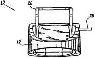
现在来看附图,其中在所有若干视图中,类似的部件由类似的附图标记指代。首先参考图1-5,其示出了根据本公开的原理构造的压迫治疗系统10。压迫治疗系统10包括外壳12。外壳12封闭布置在其中的控制器14的部件(如图5中示意性所示)。Turning now to the drawings, wherein like parts are designated by like reference numerals throughout the several views. Referring first to FIGS. 1-5 , there is shown a
外壳12具有半圆形构造并且具有沿其最高点18的提手16,以便于转移和治疗对象活动。可以想象,外壳12可以有不同的构造和尺寸,例如矩形、球形等。进一步可以想象,可以通过任何合适的工艺组装外壳12,例如搭扣配合、粘合剂、溶剂焊接、热焊、超声焊接、螺钉、铆钉等。作为另一选择,外壳12可以整体地形成或由多个外壳部分整体组装,并且可以基本上是透明的、不透明的等等。外壳12可以包括肋、脊等以便于操作压迫治疗系统10。
外壳12的部件可以由适合于医学应用的材料制造,诸如聚合物或金属(例如不锈钢),这取决于特定的医学应用和/或医生的偏好。可以预见使用半刚性和刚性聚合物,以及弹性材料,例如模制医用级聚丙烯来制造。然而,根据本公开,本领域的技术人员将理解适合于组装和制造的其它材料和制造方法也将是合适的。Components of
外壳12可携带以便于对治疗对象(未示出)进行连续血管治疗。外壳12包括便于外壳12可拆卸地安装到例如医院病床、工作台等的托架20。托架20从外壳12的后部22延伸并且提供钩状构造以用于从治疗对象的床等悬挂外壳12。可以预见,托架20可以从用于可拆卸地安装外壳12的各种结构悬挂,或者作为另一选择,外壳12并不包括托架,而是可以放置在地板或其它支撑表面上。作为另一选择,外壳12包括如图2中所示的肩带24,该肩带允许在转移期间外壳12穿戴在治疗对象或医师身上。肩带24可以使用或不使用托架20并且例如可以固定到外壳12的任何部分,包括提手16。
压迫治疗系统10使用用于操作其部件的电子AC/DC开关电源。电源线26连接到外壳12以用于将电力传导到控制器14的部件。电源线26通过壁装电源插座等接入AC电源。控制器14可以包括变压器或其它电子设备以用于连接到电源。可以想象,电源线26可以为了贮存和在转移和治疗对象活动期间缠绕托架20。进一步可以想象,所述压迫治疗系统10可以包括用外壳12保持电源线26的贮存俘获机构。所述贮存俘获机构可以包括松紧绳、滑轮等。The
压迫治疗系统10还使用为控制器14的部件供电的电池28以便于转移和治疗对象活动。电池28放置在外壳12的电池盒30内。可以预见,电池28可以包括一个或多个单元。电池单元可以是锂离子型的,等等。进一步可以预见,电池28可再充电,并且可以用于各种范围的工作时间,例如6小时、8小时、10小时,等等。例如,电源线26可以被拔掉并且由外壳12的贮存俘获机构俘获。压迫治疗系统10然后以电池28电源工作并且治疗对象可走动。
可以想象,电池28可以安装到外壳12的外表面或者与之分离。进一步可以想象,压迫治疗系统10可以包括电源的备选来源,例如太阳能、非电力等,或者作为另一选择可以不包括电池电源。It is envisioned that the battery 28 could be mounted to the outer surface of the
外壳12具有布置在其前表面34上的控制面板32。控制面板32包括用于操作压迫治疗系统10的控制器和指示器。控制面板32具有LED显示器36,该LED显示器提供系统10的各种部件的状态提示、消息等,例如功率、电池、套识别和连接、膨胀、排放、静脉回灌、错误等等。控制面板32还包括用于为系统10供电的手动开关等。可以预见,这样的开关是由指压启动的膜式开关等。The
外壳12的后部22限定端口38、40(图4)。端口38、40分别包括输出端口38a、38b、38c,和输出端口40a、40b、40c。如将要论述的,输出端口38a、38b、38c和输出端口40a、40b、40c与分别与压迫套46的可膨胀室46a、46b、46c和压迫套48的可膨胀室48a、48b、48c流体连通,所述可膨胀室被构造成通过匹配连接器42和管组44安装在治疗对象的腿周围。输出端口38a、38b、38c,40a、40b、40c构造用于连接到管组44。每个端口38、40可连接到特定压迫套,例如腿套、足套等。The rear portion 22 of the
如图5中所示的气动回路所示,端口38、40还与布置在外壳12内的控制器14的部件连接以便于膨胀选择的压迫套。如将要论述的,控制器14包括加压流体源,例如与用于连接端口38、40的阀歧管52流体连通的泵50。泵50包括通过管系等将空气压缩到阀歧管52的电动机。电子控制泵电动机的速度以按照需要为各个输出压力提供相应的压缩机速度。可以预见,本领域技术人员已知的包括必要的电子设备、电路、软件等的电源板连接到泵发动机和控制器14的其它部件以调节其功率。可以想象,泵50可以是隔膜泵。As shown in the pneumatic circuit shown in FIG. 5, the
如将要论述的,控制器14还包括止回阀54,在静脉回灌检测期间,当监视气囊压力时所述止回阀防止空气反向通过泵50泄漏。减压阀56与气动回路一起布置以防止压迫套中的过压。减压阀56被构造成必要时放出过量空气压力。可以预见,可以使用各种类型的阀,例如弹簧加力柱塞阀等。As will be discussed, the
阀歧管52包括分别联接到输出端口38a、38b、38c、40a、40b、40c的螺线管阀58a、58b、58c、60a、60b、60c。螺线管阀58a、58b、58c、60a、60b、60c均具有通过控制器14的控制处理器电子驱动的相关螺线管。螺线管联接到每个特定螺线管阀58a、58b、58c、60a、60b、60c的阀座,使得当启动螺线管时所述阀座可操作地打开和关闭各自的螺线管阀。例如参见Bock等人的美国专利No.5,876,359中描述的螺线管阀,所述专利的整个内容被结合于此以作参考。可以预见,控制器14的控制处理器包括本领域技术人员已知的必要的电子设备、电路、软件等以响应压迫治疗系统10的变化条件以及控制器14的部件所感测到的其它指示和测量而启动螺线管阀58a、58b、58c、60a、60b、60c。可以想象,可以使用一个或多个螺线管阀,或者作为另一选择,可以使用其它类型的阀。
螺线管阀58a、58b、58c、60a、60b、60c和它们的相关阀部件安装到外壳12的内部上的端口38、40。螺线管阀58a、58b、58c、60a、60b、60c是双位、三通常闭阀,其分别具有开口62a、62b、62c、64a、64b、64c。在打开位置,空气通过开口62a、62b、62c、64a、64b、64c流到相关输出端口38a、38b、38c,40a、40b、40c并且进入压迫套46的可膨胀室46a、46b、46c和压迫套48的可膨胀室48a,48b,48c。在关闭位置,开口62a、62b、62c、64a、64b、64c被堵塞,并且来自压迫套46,48的空气通过输出端口38a、38b、38c、40a、40b、40c和通过相关阀的排放端口66a、66b、66c、68a、68b、68c回流以收缩可膨胀室46a、46b、46c,48a,48b,48c。
螺线管阀58a、58b、58c、60a、60b、60c按顺序被操作以加压可膨胀室46a、46b、46c、48a、48b、48c和在控制器14的控制处理器下为其提供顺序加压和排放所述室。可以预见,当需要套的冷却操作时,螺线管阀58a、58b、58c、60a、60b、60c可以选择性地被启动,例如参见Bock等人的美国专利No.5,876,359。
螺线管阀58a、58b、58c、60a、60b、60c由控制器14的控制处理器所提供的脉冲宽度调制信号驱动。螺线管驱动信号初始处于用于快速和主动启动螺线管阀的较高功率级。在初始启动之后,可以减小驱动信号,例如减小70%以保持阀启动,由此减小功率消耗。可以想象,可以按照需要停用螺线管阀58a、58b、58c、60a、60b、60c。进一步可以想象,控制器14的控制处理器包括检验螺线管阀58a、58b、58c、60a、60b、60c的状态的能力。当螺线管阀58a、58b、58c、60a、60b、60c的条件变化时,控制处理器检验它们的状态。例如,如果检测到特定阀短路或打开,压迫治疗系统10将进入特定错误模式,这将要进行论述。The
控制器14还包括布置在外壳12内的压力传感器66。压力传感器66通过管系等联接到气动回路并且布置在泵50和螺线管阀58a、58b、58c、60a、60b、60c之间。压力传感器66与可膨胀室46a、46b、46c、48a、48b、48c流体连通以用于监视可膨胀室46a、46b、46c、48a、48b、48c的每一个中的压力。控制器14的控制处理器指导压力传感器66测量连接到它们各自的螺线管阀并因此与之流体连通的可膨胀室46a、46b、46c、48a、48b、48c中的任何一个。在螺线管阀的前面将压力传感器66布置在气动回路的歧管侧上有利地便于仅仅使用单个压力传感器以用于测量可膨胀室中的压力。该构造便于膨胀一个或多个可膨胀室。该构造还有利地减小控制器14的体积以有助于压迫治疗系统10的紧凑和轻质设计,便于转移、患者活动和减少制造成本。
例如,在选择的压迫周期期间,螺线管阀58a、58b、58c、60a、60b、60c被顺序通电以到达打开位置以用于按顺序加压可膨胀室46a、46b、46c、48a、48b、48c。在打开位置,螺线管阀58a、58b、58c、60a、60b、60c允许空气从泵50通过各自输出端口38a、38b、38c,40a、40b、40c到达可膨胀室。压力传感器66监视气动回路的可膨胀室46a、46b、46c、48a、48b、48c的每一个并且为控制器14的控制处理器提供电信号输出以用于反馈控制。For example, during selected compression cycles,
在选择的压迫周期结束时,螺线管阀58a、58b、58c、60a、60b、60c被同时断电到达用于从套46、48断开泵50的关闭位置。在关闭位置,泵50空气被堵塞并且螺线管阀58a、58b、58c、60a、60b、60c通过阀歧管52上的排放端口66a、66b、66c、68a、68b、68c将套压力排放到大气。可以预见,压迫治疗系统10可以交替膨胀第一肢体和第二肢体之间的室。进一步可以预见,压迫治疗系统10可以单独地膨胀每个气囊。At the end of the selected compression cycle, the
参考图6,与上述类似的压迫治疗系统10被组装和包装以供使用。在操作中,压迫治疗系统10包括上述的与外壳12一起布置的控制器14,和套112。套112包括大腿气囊114、小腿气囊116和踝气囊118。套112包括与匹配连接器42配合的连接器120,所述匹配连接器通过管系44连接到端口38。连接器120通过管组122与套112的室流体连通。因此,该构造便于气囊114、116、118和泵50之间的流体连通。在此可以预见,连接器120可以进一步包括控制流体流的阀机构。Referring to Figure 6, a
提供和操作套112以用于围绕治疗对象(未示出)的腿L布置。连接器120与匹配连接器42配合以在套112和气动回路之间建立流体连通。套112缠绕腿L并且通过钩和环垫124、126与之固定。可以预见,压迫治疗系统10可以用类似于套112的压迫套通过与端口40的连接治疗对象的第二条腿。如下面的备选实施方式所述,在与下述用于治疗腿L的压迫周期交替的压迫周期中治疗第二条腿。A
外壳12和控制器14的上述便携特征提供了一种便于转移和治疗对象活动的压迫治疗系统10。当在整个治疗设施使用所述系统时,该有利构造提供了不中断的DVT预防,并且可以在整个风险期由治疗对象穿戴和连续使用。在治疗对象活动和任务期间,例如为了检查而转移、去洗手间、理疗等,压迫治疗系统10有利地便于连续的血管治疗。通过提供控制器14,当未插上电源线时该控制器将用电池28带动,压迫治疗系统10防止在治疗中中断,并且还将足够舒适、紧凑和轻质以在需要时随着治疗对象一起移动。The aforementioned portability features of
控制器14的控制面板32的手动开关接通压迫治疗系统10以用于为其供电。当压迫治疗系统10初始被接通时,由控制器14的控制处理器进行一系列自测试。显示器36的LED指示器被点亮并且可听到提示发声以检验视听指示器的可操作性。显示器36被打开以检验显示器可操作性。控制器14还检验控制处理器的软件的可操作性。如果任何一个检验失败,错误代码提供代表性可听和/或可视提示。A manual switch on the
可以预见,如果控制器14的控制处理器不能继续正常的软件运行,错误代码将被触发。这导致压迫治疗系统10重置并且重新启动正常操作。套112将在重新启动程序期间排放。可听和可视提示还可以用于代表条件。It is foreseeable that error codes will be triggered if the control processor of
一旦完成用于压迫治疗系统10的自测试序列,控制器14开始套检测程序以确定连接到端口38、40的套的一种或多种类型。在控制器14初始被通电之后在第一膨胀(检测)周期期间进行套检测。在所述检测周期期间,使泵50工作两秒,或者直到压力到达缺省阈值,空气被交替地输送通过端口38、40。一秒后,压力传感器66在套检测下进行压力测量以确定气囊是否连接到特定输出端口38a、38b、38c,40a、40b或40c。Once the self-test sequence for
例如,为用于套端口38、40的每一个进行气囊114、116、118的检测程序。如果在用于与气囊连接的特定出口端口没有反压力,则控制器14的控制处理器确定气囊未用于特定出口端口。所述控制处理器相应地为检测到的套构造调节压迫治疗。对于3气囊套,当连接到控制器14时在气囊114、116、118检测到反压力。可以预见,如果该程序在端口38或40未检测到套,或者如果检测到的构造未被识别。则由相应的可听提示触发低压错误。进一步可以预见,根据特定应用的要求,可以使用用于检测膨胀和压力测量的各种延迟期间。For example, a testing procedure for the
作为另一选择,大腿气囊114可从小腿气囊116拆除。例如,小腿气囊116通过有孔连接件可拆除地连接到大腿气囊114,例如参见2004年2月23日公开的、发明名称为“压迫装置”的、序列号为No.10/784,607的美国专利申请中所描述的套,所述申请的全部内容被结合于此以作参考。对于可拆除大腿气囊114,控制器14的控制处理器执行类似的套检测程序,如上所述。控制处理器将由于配备连接器120的流动限制阀(未示出)检测3气囊套。例如参见2004年2月23日公开的、发明名称为“流体通道连接器装置”的、序列号为No.10/784,639的美国专利申请中所描述的流动限制阀,所述申请的全部内容被结合于此以作参考。当实际上没有连接的气囊时所述流动限制阀模拟大腿114产生的反压力。因此,从3气囊大腿长度套转变到2气囊膝盖长度套并不显著影响压迫参数,并且控制器14继续血管治疗,就如同大腿114仍然完整。As another option, the
在一个备选实施方式中,如图7中所示,套112包括大腿气囊114和单式第二气囊218。第二气囊218具有小腿部分220和踝部分222。泵50通过阀连接器224和独立管系226、228与套112流体地连通,以与上述类似地使用,包括通过穿孔等可选择地拆卸大腿114。In an alternative embodiment, as shown in FIG. 7 , the
在用于压迫治疗系统10的一个特定压迫周期中,压迫参数包括用于膨胀气囊114、116、118的11秒的膨胀期,接着是用于收缩气囊114、116、118的60秒的排放。11秒的膨胀期是按顺序的:In one particular compression cycle for the
1)在0秒开始初始膨胀踝气囊118并持续第一时间段;1) Initial inflation of the
2)其后和在第一时间段期间,开始膨胀小腿气囊116并持续第二时间段,第二时间段的开始与第一时间段的大约2.67秒的持续时间重合;2) Thereafter and during the first period of time, the
3)其后和在第二时间段期间,开始膨胀大腿气囊114并持续第三时间段,第三时间段的开始与第二时间段的大约3.0秒的持续时间和第一时间段的大约5.67秒的持续时间重合;3) Thereafter and during the second time period, begin to inflate the
4)在第一时间段的11秒之后,排放气囊114、116和118并持续最少20秒最多60秒。在下面的表1中示出了一个例子。4) After 11 seconds of the first time period,
表1Table 1

可以预见,在腿L上从第一膨胀周期结束到下一膨胀周期开始测量排放周期。进一步可以预见,治疗对象的两个肢体可以被治疗并且压迫治疗系统10从腿L到第二条腿交替进行血管治疗。可以想象,从用于腿L的膨胀周期结束到用于第二条腿的膨胀周期开始的时间段可以在4.5-24.5秒内变化。It is foreseen that the discharge period is measured on leg L from the end of the first expansion period to the beginning of the next expansion period. It is further contemplated that both limbs of a subject may be treated and
在如上所述的用于治疗腿L的初始膨胀周期期间,泵50启动缺省低电压,从而在初始周期不过膨胀气囊114、116、118。螺线管阀58a、58b、58c被通电以到达如上所述的打开位置,使得所述阀打开以使用期望的周期时序将空气输送至踝气囊118,然后至小腿气囊116,然后至套112的大腿气囊114。压力传感器66在整个11秒的压迫周期监视气囊114、116、118的每一个中的压力。在膨胀周期结束时,泵50停止并且螺线管阀58a、58b、58c断电以到达关闭位置,从而通过排放端口66a、66b、66c允许气囊114、116、118收缩。During the initial inflation cycle for treating leg L as described above, the
可以想象,如果治疗对象的第二条腿以用于血管治疗,螺线管阀60a、60b、60c被通电以到达如上所述的打开位置,使得所述阀打开以使用期望的周期时序将空气输送至类似于套112的围绕第二条腿布置的套的相应气囊。压力传感器66在整个11秒的压迫周期监视所述相应气囊的每一个中的压力。在膨胀周期结束时,泵50停止并且螺线管阀60a、60b、60c断电以到达关闭位置,从而通过排放端口68a、68b、68c允许所述相应气囊收缩。进一步可以预见,用于治疗第二条腿的膨胀周期可以在完成用于治疗腿L的膨胀周期之后大约24.5秒开始。可以为与两条腿有关的周期重复该过程。It is conceivable that if a subject's second leg is being treated for vascular therapy, the
在该实施方式中,在膨胀周期期间由压力传感器66和中继到控制器14的控制处理器的相应信号测量的气囊114、116、118的压力保持梯度,踝气囊118的压力大于小腿气囊116的压力,小腿气囊116的压力大于大腿气囊114的压力。周期结束压力例如包括,在踝气囊118中为45mmHg,在小腿气囊116中为40mmHg,在大腿气囊114中为30mmHg。在下面的表2中示出了一个例子。可以预见,在该周期模式中压迫继续,直到压迫治疗系统10关闭或控制器14通过可听或可视提示指示错误代码。还可以预见其它周期压力。In this embodiment, the gradient is maintained during the inflation cycle in the pressure of the
表2Table 2

对于所述的用于腿L的初始膨胀周期以后的膨胀周期,可以按照压力传感器66进行的压力测量进行压力反馈调节。在用于腿L的初始膨胀周期结束时,踝气囊118中的周期结束压力由压力传感器66测量并且由控制器14的控制处理器与45mmHg的设定压力比较。如果踝气囊118的压力高于或低于设定压力,则需要泵50的速度相应减小或增加以减小或增加压力输送。泵速调节基于以下计算:For inflation cycles after the initial inflation cycle described for the leg L, pressure feedback adjustments may be made according to pressure measurements made by the
调节=|45-P|,其中P=在踝处的压力。Conditioning = |45-P|, where P = pressure at the ankle.
如果所述压力小于设定压力,则用于下一个周期的泵速被增加调节量。如果所述压力大于设定压力,则用于下一个周期的泵速被减小调节量。可以预见,甚至在达到设定压力范围之后调节过程还继续。进一步可以预见,压迫治疗系统10可以为连接到控制器14的每个套调节独立泵速。还可以预见其它顺序压迫周期。If the pressure is less than the set pressure, the pump speed for the next cycle is increased by the adjustment amount. If the pressure is greater than the set pressure, the pump speed for the next cycle is reduced by the adjustment amount. It is foreseeable that the regulation process continues even after the set pressure range is reached. It is further contemplated that
在一个备选实施方式中,压迫治疗系统10执行静脉回灌时间测量。静脉回灌时间(VRT)测量是空气体积描记技术,该技术确定在压迫周期之后肢体的静脉何时完全被血液回灌。例如参见Watson等人的美国专利No.6,231,352中所描述的静脉回灌时间测量,所述专利的全部内容被结合于此以作参考。VRT使血液在静脉内保持停滞的时间长度最小化。VRT将替代缺省休息时间(60秒),前提是VRT在20-60秒。如果VRT小于20秒,则使用20秒的缺省值。如果VRT大于60秒,则使用60秒的最大值。当系统首次到达设定压力并且在其后的每30分钟进行VRT测量。可以预见,VRT技术和算法可以用于套和足压迫两者。In an alternative embodiment,
VRT测量使用空气体积描记技术,其中对小腿气囊施加低压。当静脉被血液灌注时,小腿气囊中的压力增加,直到达到平稳。使压力达到平稳所用的时间是VRT。如果两个套连接到控制器14,则单独地为每个正被压迫的肢体确定VRT并且两个测量中的较大者被用作压迫周期的新排放时间。当每个特定套独立地达到设定压力时为每个套进行VRT测量。然而,并不更新排放时间,直到已为两个套计算出VRT测量。VRT measurements use the air plethysmography technique, in which a low pressure is applied to the calf air sac. As the veins are filled with blood, the pressure in the calf air sac increases until it plateaus. The time it takes for the pressure to plateau is VRT. If two cuffs are connected to the
例如,压迫治疗系统10可以在系统开始血管治疗之后使用VRT测量。随后,在30分钟过去之后,将在下一个完整膨胀周期进行VRT测量。在上述套中的任何一个膨胀之后,特定套的一个或多个气囊在缺省膨胀周期中被排放降到零。For example,
可以预见,当压力下降到5-7mmHg时所选气囊压力被监视和气囊的排放口被关闭。如果在当前的周期气囊中的压力为5-7mmHg,则进行VRT测量。如果气囊中的压力并不排放降到5-7mmHg,则排放时间降保持在其当前值并且降在30分钟内进行另一测量。如果发生错误,则相应的警报提供可听和/或可视提示。It is foreseeable that the selected balloon pressure is monitored and the vent of the balloon is closed when the pressure drops to 5-7 mmHg. If the pressure in the cuff is 5-7 mmHg during the current cycle, perform a VRT measurement. If the pressure in the bladder does not vent down to 5-7 mmHg, the vent time is kept at its current value and another measurement is taken within 30 minutes. If errors occur, corresponding alarms provide audible and/or visual reminders.
VRT测量算法确定所选气囊中的压力在压迫之后何时平稳。将单独地为两条腿确定VRT。两个回灌时间的较长者将被用作新排放时间。如果仅仅对一条腿施加压迫,则用于那条腿的VRT被用作新排放时间。VRT测量算法始于从膨胀周期结束时开始的计时器,所述膨胀周期发生在所选气囊达到5-7mmHg(导致气囊保持与腿的表面接触的足够压力)并且排放停止之后。VRT测量算法始于从所述膨胀周期结束时开始的计时器。The VRT measurement algorithm determines when the pressure in the selected balloon plateaus after compression. VRT will be determined for both legs individually. The longer of the two recharge times will be used as the new discharge time. If compression is applied to only one leg, the VRT for that leg is used as the new discharge time. The VRT measurement algorithm begins with a timer starting at the end of the inflation cycle that occurs after the selected balloon reaches 5-7 mmHg (sufficient pressure to cause the balloon to remain in contact with the surface of the leg) and discharge ceases. The VRT measurement algorithm starts with a timer starting from the end of the inflation cycle.
然后监视所选气囊中的压力。作为例子,用10秒的移动采样窗口监视所述压力。所述窗口以1秒的时间间隔移动。当当窗口中的第一和最后值之间的差值小于大约0.3mmHg时曲线达到其平稳阶段。VRT测量被视为已完成,并且时段被确定。窗口的终点被视为肢体中的静脉系统回灌的点。The pressure in the selected bladder is then monitored. As an example, the pressure is monitored with a moving sampling window of 10 seconds. The window moves at 1 second intervals. The curve reaches its plateau when the difference between the first and last values in the window is less than about 0.3 mmHg. The VRT measurement is considered complete and the time period is determined. The endpoint of the window is considered the point of refill of the venous system in the limb.
不依赖于VRT测量,在相同肢体上的下一个压迫周期开始之前允许所选气囊排放至少15秒。作为安全系数,为测量的回灌时间增加5秒,从而不会过早压迫肢体。可以预见,排放时间可以等于测量的回灌时间加上5秒。例如,作为患者移动的结果,采样窗口中的标准偏差可能太高,从而使测量出现错误。在这一点上,计算结果被丢弃并且使用以前的VRT值。如果在测量期间的任何时间所选气囊中的压力小于2mmHg,则VRT测量被视为是错误的,计算结果被丢弃,并且使用以前的VRT值。这可能发生在系统中存在泄漏的情况下。可以预见,如果在VRT测量期间的任何时间压力大于20mmHg,则使用以前的VRT值。进一步可以预见,如果为两条腿进行了VRT测量,则使用两条腿的较长VRT。可以想象,如果计算出的VRT大于60秒,则使用60秒的值。如果计算出的VRT小于20秒,则使用20秒的值。Independent of VRT measurements, the selected balloon was allowed to deflate for at least 15 seconds before the next compression cycle on the same limb began. As a safety factor, add 5 seconds to the measured recharge time so that the limb is not compressed prematurely. It is envisioned that the discharge time may be equal to the measured refill time plus 5 seconds. For example, as a result of patient movement, the standard deviation in the sampling window may be too high, making measurements erroneous. At this point, the calculation result is discarded and the previous VRT value is used. If at any time during the measurement period the pressure in the selected balloon is less than 2 mmHg, the VRT measurement is considered to be erroneous, the calculation is discarded, and the previous VRT value is used. This can happen if there is a leak in the system. It is foreseeable that if the pressure is greater than 20 mmHg at any time during the VRT measurement, the previous VRT value is used. It is further foreseen that if VRT measurements are made for both legs, the longer VRT for both legs is used. Conceivably, if the calculated VRT is greater than 60 seconds, a value of 60 seconds is used. If the calculated VRT is less than 20 seconds, the value of 20 seconds is used.
作为另一选择,压迫治疗系统10可以使用以下错误代码中的一个、多个或全部以提供系统错误或故障的可听和/或可视提示。这些特征有利地增强了血管治疗期间治疗对象的安全性。若干错误条件可以导致压迫治疗系统10提供警报和停止特定的压迫周期。可以预见,压迫治疗系统10可以闪耀错误指示器,发出连续信号声,等等,导致使用者重置压迫治疗系统10。控制器14可以为以下错误条件中的一个、多个或全部提供错误警报:高压错误,包括超过设定压力的那些测定压力;低压错误,包括低于设定压力的那些测定压力以及没有检测到套;系统压力错误,包括在膨胀周期内确定的在期望的参数之外的压力;阀错误;软件错误;泵错误;排放和收缩错误;电池错误;和温度错误,包括在特定的环境条件之外的测定温度。Alternatively,
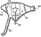
在一个备选实施方式中,如图8中所示,与上述类型的压迫治疗系统10包括被构造成为治疗对象的足提供血管治疗的足套312。足套312包括气囊314,所述气囊用空气膨胀以对足施加压力并且然后收缩。例如参见2004年2月23日公开的、发明名称为“压迫装置”的、序列号为No.10/784,604的美国专利申请中所描述的套,所述申请的全部内容被结合于此以作参考。In an alternative embodiment, as shown in FIG. 8, a
泵50与足套312流体地连通。套312包括与匹配连接器42配合的连接器316,所述匹配连接器通过管系44连接到端口40。阀连接器316通过管系318与套312的气囊314流体连通。因此,该构造便于气囊314和泵50之间的流体连通。足套312通过横穿足的足背的钩和环型连接片320以及钩和环型连接踝带322缠绕足的侧部。
一旦完成类似于所述的用于治疗系统10的自测试顺序压迫,控制器14开始套检测程序以确定连接到端口38、40的套的一个或多个类型。关于足套312,由对应于气囊314的控制器14的控制处理器检测反压力,所述气囊连接到出口端口40b。可以预见,压迫治疗系统10可以用足套312治疗对象的第二条腿的足并且如上所述还在交替膨胀周期中治疗腿L。Once a self-test sequence compression similar to that described for
在用于足套312的一个特定的典型压迫周期中,压迫参数包括5秒的膨胀期,接着是60秒的排放。在下面的表3中示出了一个例子。In one particular typical compression cycle for
表3table 3

可以预见,在治疗对象的足上从一个膨胀周期结束到下一个膨胀周期开始测量排放期。进一步可以预见,治疗对象的两个肢体可以被治疗并且压迫治疗系统10从腿L到第二条腿交替进行血管治疗。可以想象,从用于腿L的膨胀周期结束到用于第二条腿的膨胀周期开始的时间段可以在7.5-27.5秒内变化。It is envisioned that the discharge period is measured on the subject's foot from the end of one inflation cycle to the beginning of the next inflation cycle. It is further contemplated that both limbs of a subject may be treated and
在如上所述的用于治疗对象的足的初始膨胀周期期间,泵50启动缺省低电压,从而在初始周期不过膨胀气囊314。螺线管阀60b被通电以到达如上所述的打开位置,使得所述阀打开以使用期望的周期时序将空气输送至气囊314。压力传感器66在整个5秒的压迫周期监视气囊314中的压力。在膨胀周期结束时,泵50停止并且螺线管阀60b断电以到达关闭位置,从而通过排放端口68b允许气囊314收缩。During the initial inflation cycle as described above for treating a subject's foot, the
可以想象,如果治疗对象的第二只足以用于血管治疗,螺线管阀58b被通电以到达如上所述的打开位置,使得所述阀打开以使用期望的周期时序将空气输送至类似于足套312的围绕另一条腿布置的足套的相应气囊。例如,压力传感器66在整个5秒的压迫周期监视所述相应气囊中的压力。在膨胀周期结束时,泵50停止并且螺线管阀58b断电以到达关闭位置,从而通过排放端口66b允许所述相应气囊收缩。进一步可以预见,用于治疗第二只足的膨胀周期可以在完成用于治疗足套312所治疗的足的膨胀周期之后大约27.5秒开始。可以为与两只足有关的周期重复该过程,或者作为另一选择,为第一条腿的足套和第二条腿的腿套重复该过程。可以预见,压迫治疗系统10可以为套和足套的任何组合提供交替压迫,如果使用这样的组合,则在足膨胀周期之后为所有排放期增加例如附加排放时间的6秒缓冲,从而总时间与缺省套压迫参数一致。可以预见其它周期时间。It is conceivable that if the second of the subject being treated is sufficient for vascular therapy, the solenoid valve 58b is energized to the open position as described above, so that the valve opens to deliver air to a similar foot using the desired cycle timing. The corresponding bladder of the boot of the
在该实施方式中,由压力传感器66和中继到控制器14的控制处理器的相应信号测量的目的压力例如为130mmHg。可以预见,压迫在该周期模式中继续,直到压迫治疗系统10被关闭或控制器14通过可听或可视提示指示错误代码。In this embodiment, the target pressure measured by the
对于所述用于足套312的初始膨胀周期以后的膨胀周期,可以按照压力传感器66进行的压力测量进行压力反馈调节。在用于足套312的初始膨胀周期结束时,气囊314中的周期结束压力由压力传感器66测量并且由控制器14的控制处理器与130mmHg的设定压力比较。如果气囊314的压力高于或低于设定压力,则需要泵50的速度相应减小或增加以减小或增加压力输送。泵速调节基于以下计算:For inflation cycles after the initial inflation cycle described for
调节=|130-P|,其中P=在足处的压力。Conditioning = |130-P|, where P = pressure at the foot.
如果所述压力小于设定压力,则用于下一个周期的泵速被增加调节量。如果所述压力大于设定压力,则用于下一个周期的泵速被减小调节量。可以预见,甚至在达到设定压力范围之后调节过程还继续。进一步可以预见,压迫治疗系统10可以为连接到控制器14的每个套调节独立泵速。还可以预见其它顺序压迫周期。If the pressure is less than the set pressure, the pump speed for the next cycle is increased by the adjustment amount. If the pressure is greater than the set pressure, the pump speed for the next cycle is reduced by the adjustment amount. It is foreseeable that the regulation process continues even after the set pressure range is reached. It is further contemplated that
将会理解,可以对在此公开的实施方式进行各种修改。所以,以上描述不应当被理解成限制,而是应当仅仅被理解成各种实施方式的举例。在后附于此的权利要求的范围和精神内本领域的技术人员将可以想象其它修改。It will be understood that various modifications may be made to the embodiments disclosed herein. Therefore, the above description should not be read as limiting, but merely as exemplifications of various embodiments. Those skilled in the art will envision other modifications within the scope and spirit of the claims appended hereto.
Claims (5)
Translated fromChineseApplications Claiming Priority (9)
| Application Number | Priority Date | Filing Date | Title |
|---|---|---|---|
| US10/784,607US7871387B2 (en) | 2004-02-23 | 2004-02-23 | Compression sleeve convertible in length |
| US10/784,607 | 2004-02-23 | ||
| US10/784,639US7490620B2 (en) | 2004-02-23 | 2004-02-23 | Fluid conduit connector apparatus |
| US10/784,323US7354410B2 (en) | 2004-02-23 | 2004-02-23 | Compression treatment system |
| US10/784,604US7282038B2 (en) | 2004-02-23 | 2004-02-23 | Compression apparatus |
| US10/784,604 | 2004-02-23 | ||
| US10/784,639 | 2004-02-23 | ||
| US10/784,323 | 2004-02-23 | ||
| CN2005800043260ACN1917842B (en) | 2004-02-23 | 2005-02-23 | compression therapy system |
Related Parent Applications (1)
| Application Number | Title | Priority Date | Filing Date |
|---|---|---|---|
| CN2005800043260ADivisionCN1917842B (en) | 2004-02-23 | 2005-02-23 | compression therapy system |
Publications (2)
| Publication Number | Publication Date |
|---|---|
| CN102614074Atrue CN102614074A (en) | 2012-08-01 |
| CN102614074B CN102614074B (en) | 2015-09-23 |
Family
ID=34916527
Family Applications (1)
| Application Number | Title | Priority Date | Filing Date |
|---|---|---|---|
| CN201210098027.XAExpired - LifetimeCN102614074B (en) | 2004-02-23 | 2005-02-23 | Compression therapeutic apparatus |
Country Status (14)
| Country | Link |
|---|---|
| EP (6) | EP1720505B1 (en) |
| JP (4) | JP2007522892A (en) |
| KR (5) | KR20070001964A (en) |
| CN (1) | CN102614074B (en) |
| AT (3) | ATE468834T1 (en) |
| AU (4) | AU2005216924B2 (en) |
| CA (4) | CA2552354C (en) |
| DE (2) | DE602005022165D1 (en) |
| DK (1) | DK1720504T3 (en) |
| ES (4) | ES2414880T3 (en) |
| IL (4) | IL176410A (en) |
| NO (4) | NO20064256L (en) |
| PL (2) | PL1720505T3 (en) |
| WO (4) | WO2005083313A1 (en) |
Cited By (2)
| Publication number | Priority date | Publication date | Assignee | Title |
|---|---|---|---|---|
| CN106038198A (en)* | 2015-04-09 | 2016-10-26 | 康斯博格汽车股份公司 | Massage device for vehicle seat |
| CN109219427A (en)* | 2016-05-26 | 2019-01-15 | 亨特来夫工业技术有限公司 | Compression therapeutic apparatus and method |
Families Citing this family (64)
| Publication number | Priority date | Publication date | Assignee | Title |
|---|---|---|---|---|
| GB0515294D0 (en) | 2005-07-26 | 2005-08-31 | Novamedix Distrib Ltd | Limited durability closure means for an inflatable medical garment |
| GB0523249D0 (en)* | 2005-11-15 | 2005-12-21 | Huntleigh Technology Plc | Identification means |
| US8029451B2 (en) | 2005-12-12 | 2011-10-04 | Tyco Healthcare Group Lp | Compression sleeve having air conduits |
| GB0601453D0 (en)* | 2006-01-24 | 2006-03-08 | Bristol Myers Squibb Co | Pressurised medical device |
| JP4710758B2 (en)* | 2006-08-28 | 2011-06-29 | パナソニック電工株式会社 | Massage machine |
| GB0622415D0 (en) | 2006-11-10 | 2006-12-20 | Huntleigh Technology Plc | Compression system |
| US8109892B2 (en) | 2007-04-09 | 2012-02-07 | Tyco Healthcare Group Lp | Methods of making compression device with improved evaporation |
| US8016778B2 (en) | 2007-04-09 | 2011-09-13 | Tyco Healthcare Group Lp | Compression device with improved moisture evaporation |
| US8029450B2 (en) | 2007-04-09 | 2011-10-04 | Tyco Healthcare Group Lp | Breathable compression device |
| US8070699B2 (en) | 2007-04-09 | 2011-12-06 | Tyco Healthcare Group Lp | Method of making compression sleeve with structural support features |
| US8016779B2 (en)* | 2007-04-09 | 2011-09-13 | Tyco Healthcare Group Lp | Compression device having cooling capability |
| US8162861B2 (en) | 2007-04-09 | 2012-04-24 | Tyco Healthcare Group Lp | Compression device with strategic weld construction |
| US8128584B2 (en) | 2007-04-09 | 2012-03-06 | Tyco Healthcare Group Lp | Compression device with S-shaped bladder |
| US8034007B2 (en) | 2007-04-09 | 2011-10-11 | Tyco Healthcare Group Lp | Compression device with structural support features |
| US8021388B2 (en) | 2007-04-09 | 2011-09-20 | Tyco Healthcare Group Lp | Compression device with improved moisture evaporation |
| US8506508B2 (en) | 2007-04-09 | 2013-08-13 | Covidien Lp | Compression device having weld seam moisture transfer |
| US8182437B2 (en) | 2007-05-08 | 2012-05-22 | Wright Therapy Products, Inc. | Pneumatic compression therapy system and methods of using same |
| EP2162109A4 (en) | 2007-06-20 | 2012-10-03 | Remo Moomiaie-Qajar | Portable compression device |
| GB0712764D0 (en) | 2007-07-02 | 2007-08-08 | Smith & Nephew | Carrying Bag |
| US8246028B2 (en) | 2007-11-08 | 2012-08-21 | Tyco Healthcare Group Lp | Telescopingly adjustable clamp |
| US8114117B2 (en) | 2008-09-30 | 2012-02-14 | Tyco Healthcare Group Lp | Compression device with wear area |
| US8235923B2 (en) | 2008-09-30 | 2012-08-07 | Tyco Healthcare Group Lp | Compression device with removable portion |
| US8133039B2 (en)* | 2009-01-26 | 2012-03-13 | Tyco Healthcare Group Lp | Mount for a compression control unit |
| US8419666B2 (en)* | 2009-09-23 | 2013-04-16 | Caremed Supply, Inc. | Compression sleeve |
| US8506507B2 (en)* | 2010-03-09 | 2013-08-13 | Covidien Lp | Venous augmentation system |
| US8652079B2 (en) | 2010-04-02 | 2014-02-18 | Covidien Lp | Compression garment having an extension |
| USD675741S1 (en) | 2010-08-16 | 2013-02-05 | Covidien Lp | Pneumatic compression controller |
| USD659839S1 (en) | 2010-08-16 | 2012-05-15 | Tyco Healthcare Group Lp | Support for a pneumatic compression controller |
| US10751221B2 (en) | 2010-09-14 | 2020-08-25 | Kpr U.S., Llc | Compression sleeve with improved position retention |
| US8398572B2 (en)* | 2010-09-21 | 2013-03-19 | Covidien Lp | Bladder tube connection |
| US8753300B2 (en) | 2010-09-29 | 2014-06-17 | Covidien Lp | Compression garment apparatus having baseline pressure |
| US8758282B2 (en) | 2010-09-29 | 2014-06-24 | Covidien Lp | Compression garment apparatus having support bladder |
| CA2778395A1 (en)* | 2011-06-10 | 2012-12-10 | Tyco Healthcare Group Lp | Compression device having a pause feature |
| US10828402B2 (en)* | 2011-10-14 | 2020-11-10 | Alcon Inc. | Collar connector |
| AU2013232352B2 (en) | 2012-03-12 | 2017-10-12 | Tactile Systems Technology, Inc. | Compression therapy device with multiple simultaneously active chambers |
| US9889063B2 (en) | 2012-06-11 | 2018-02-13 | Wright Therapy Products, Inc. | Methods and systems for determining use compliance of a compression therapy device |
| US9205021B2 (en) | 2012-06-18 | 2015-12-08 | Covidien Lp | Compression system with vent cooling feature |
| WO2014021267A1 (en)* | 2012-07-30 | 2014-02-06 | 国立大学法人高知大学 | In vivo acetylcholine production-promoting device |
| EP2884894B1 (en) | 2012-08-18 | 2021-06-16 | Tactile Systems Technology, Inc. | Methods for determining the size of body parts as part of compression therapy procedures |
| US9872812B2 (en) | 2012-09-28 | 2018-01-23 | Kpr U.S., Llc | Residual pressure control in a compression device |
| USD764654S1 (en) | 2014-03-13 | 2016-08-23 | Smith & Nephew, Inc. | Canister for collecting wound exudate |
| US9295605B2 (en) | 2013-12-02 | 2016-03-29 | Wright Therapy Products, Inc. | Methods and systems for auto-calibration of a pneumatic compression device |
| US10470967B2 (en) | 2014-01-20 | 2019-11-12 | Tactile Systems Technology, Inc. | Bespoke compression therapy device |
| US10292894B2 (en) | 2014-02-11 | 2019-05-21 | Tactile Systems Technology, Inc. | Compression therapy device and compression therapy protocols |
| USD764047S1 (en) | 2014-05-28 | 2016-08-16 | Smith & Nephew, Inc. | Therapy unit assembly |
| USD764653S1 (en) | 2014-05-28 | 2016-08-23 | Smith & Nephew, Inc. | Canister for collecting wound exudate |
| USD764048S1 (en) | 2014-05-28 | 2016-08-16 | Smith & Nephew, Inc. | Device for applying negative pressure to a wound |
| USD770173S1 (en) | 2014-06-02 | 2016-11-01 | Smith & Nephew, Inc. | Bag |
| USD765830S1 (en) | 2014-06-02 | 2016-09-06 | Smith & Nephew, Inc. | Therapy unit assembly |
| US10071011B2 (en) | 2014-06-30 | 2018-09-11 | Kpr U.S., Llc | Compression garment inflation |
| AU2015308928B2 (en)* | 2014-08-27 | 2019-03-14 | Kpr U.S., Llc | Compression garment inflation |
| JP6787903B2 (en) | 2015-01-27 | 2020-11-18 | メディヴァンス インコーポレイテッドMedivance,Inc. | Improved medical pads and systems for hyperthermia |
| US10076462B2 (en) | 2016-04-27 | 2018-09-18 | Radial Medical, Inc. | Adaptive compression therapy systems and methods |
| WO2018230930A1 (en)* | 2017-06-16 | 2018-12-20 | 주식회사 뷰엘리스 | Leg cuff for pneumatic massage |
| US11980565B2 (en) | 2018-03-23 | 2024-05-14 | TurnCare, Inc. | Inflatable perfusion enhancement apparatuses and associated devices, systems and methods |
| US11504927B2 (en) | 2018-03-23 | 2022-11-22 | TurnCare, Inc. | Systems and methods for controlling and monitoring inflatable perfusion enhancement apparatus for mitigating contact pressure |
| JP6813531B2 (en)* | 2018-05-16 | 2021-01-13 | 日東工器株式会社 | Pneumatic massage device and its air supply tube |
| US10893998B2 (en) | 2018-10-10 | 2021-01-19 | Inova Labs Inc. | Compression apparatus and systems for circulatory disorders |
| AU2021275323A1 (en) | 2020-05-22 | 2022-12-22 | Kpr U.S., Llc | System, method, and device utilizing reversible connector |
| KR20220019182A (en) | 2020-08-07 | 2022-02-16 | 유인종 | An air pressure control apparatus for treatment apparatus of varicose vein and the treatment apparatus comprising the same |
| KR20220019180A (en) | 2020-08-07 | 2022-02-16 | 유인종 | A compression stocking for treatment apparatus of varicose vein and the fabrication method thereof, and the treatment apparatus comprising the same |
| US12433785B2 (en) | 2021-02-23 | 2025-10-07 | C. R. Bard, Inc. | Gel pad assembly using free rotatable fluid joints |
| US12241570B2 (en) | 2021-07-07 | 2025-03-04 | C. R. Bard, Inc. | Negative pressure connector seal |
| JP7283816B1 (en)* | 2022-02-17 | 2023-05-30 | 株式会社テクノ高槻 | Air supply and exhaust system |
Citations (4)
| Publication number | Priority date | Publication date | Assignee | Title |
|---|---|---|---|---|
| EP0552515A1 (en)* | 1991-11-25 | 1993-07-28 | The Kendall Company | Compression therapy device |
| US5575762A (en)* | 1994-04-05 | 1996-11-19 | Beiersdorf-Jobst, Inc. | Gradient sequential compression system and method for reducing the occurrence of deep vein thrombosis |
| EP1018329A2 (en)* | 1998-12-28 | 2000-07-12 | Nitto Kohki Co., Ltd. | Air massage system |
| CN1292672A (en)* | 1999-01-11 | 2001-04-25 | 家族株式会社 | Massaging machine |
Family Cites Families (43)
| Publication number | Priority date | Publication date | Assignee | Title |
|---|---|---|---|---|
| US1883240A (en)* | 1925-11-27 | 1932-10-18 | Honeywell Regulator Co | Magnetically operated valve |
| US1608239A (en) | 1925-12-09 | 1926-11-23 | Rosett Joshua | Therapeutic device |
| US2628850A (en)* | 1949-03-19 | 1953-02-17 | Donald V Summerville | Releasable conduit connection with automatic valving |
| US4013069A (en)* | 1975-10-28 | 1977-03-22 | The Kendall Company | Sequential intermittent compression device |
| US4091804A (en)* | 1976-12-10 | 1978-05-30 | The Kendall Company | Compression sleeve |
| US4355632A (en)* | 1980-08-06 | 1982-10-26 | Jobst Institute, Inc. | Anti-shock pressure garment |
| US4374518A (en)* | 1980-10-09 | 1983-02-22 | Raul Villanueva | Electronic device for pneumomassage to reduce lymphedema |
| JPS5942030Y2 (en)* | 1980-12-23 | 1984-12-06 | 株式会社日器 | Pressure bag for pneumatic pine surge device |
| IL63574A (en) | 1981-08-14 | 1985-07-31 | Mego Afek | Massaging sleeve for body limbs |
| JPS5892926U (en)* | 1981-12-17 | 1983-06-23 | 日東工器株式会社 | Compressed air supply device for pneumatic pine surger |
| US4624248A (en)* | 1983-02-07 | 1986-11-25 | David Clark Company Incorporated | Transparent pressure garment |
| US4696289C1 (en)* | 1983-06-22 | 2002-09-03 | Novamedix Distrib Ltd | Method of stimulating the venous-pump mechanism of the foot and for enhancement of arterial flow to the foot |
| US5989204A (en)* | 1991-09-27 | 1999-11-23 | Kinetic Concepts, Inc. | Foot-mounted venous compression device |
| DE69232191T2 (en)* | 1991-12-17 | 2002-08-29 | Kinetic Concepts, Inc. | PNEUMATIC COMPRESSION DEVICE FOR USE IN THE MEDICAL AREA |
| GB2295235B (en)* | 1992-09-15 | 1996-08-14 | Huntleigh Technology Plc | DVT prevention apparatus and method |
| JPH06245949A (en)* | 1993-02-22 | 1994-09-06 | Hokoku Kogyo Co Ltd | Warming/cooling massage medical treatment device |
| US5354260A (en)* | 1993-05-13 | 1994-10-11 | Novamedix, Ltd. | Slipper with an inflatable foot pump |
| US5443440A (en)* | 1993-06-11 | 1995-08-22 | Ndm Acquisition Corp. | Medical pumping apparatus |
| US5478119A (en)* | 1993-09-16 | 1995-12-26 | The Kendall Company | Polarized manifold connection device |
| US5795312A (en)* | 1993-09-27 | 1998-08-18 | The Kendall Company | Compression sleeve |
| US5591200A (en)* | 1994-06-17 | 1997-01-07 | World, Inc. | Method and apparatus for applying pressure to a body limb for treating edema |
| CA2153375C (en)* | 1994-07-26 | 2000-09-12 | Arnold Tobler | Attachment of hook and loop fastener to a compression sleeve |
| US5876359A (en) | 1994-11-14 | 1999-03-02 | Bock; Malcolm G. | Sequential compression device controller |
| GB9507328D0 (en)* | 1995-04-08 | 1995-05-31 | Novamedix Ltd | A medical device |
| JPH09313557A (en)* | 1996-05-31 | 1997-12-09 | Megoafeck Ind Measuring Instr | Pneumatic massage device |
| IL120935A0 (en)* | 1996-06-07 | 1997-09-30 | Bibi Roni | Medical apparatus for facilitating blood circulation in the lower limbs |
| US5681339A (en)* | 1996-08-12 | 1997-10-28 | Mcewen; James A. | Apparatus and method for monitoring the patency of tubing in a pneumatic medical device |
| JP4124503B2 (en)* | 1997-06-06 | 2008-07-23 | 株式会社アドバンス | Blood circulation promotion device |
| JP4059956B2 (en)* | 1997-06-30 | 2008-03-12 | 日東工器株式会社 | Pneumatic massager |
| ES2212327T3 (en)* | 1997-08-31 | 2004-07-16 | Medical Compression Systems (D.B.N.) | DEVICE FOR APPLYING PRESSURE TO BODY EXTREMITIES. |
| US6494852B1 (en) | 1998-03-11 | 2002-12-17 | Medical Compression Systems (Dbn) Ltd. | Portable ambulant pneumatic compression system |
| US6007559A (en)* | 1998-06-12 | 1999-12-28 | Aci Medical | Vascular assist methods and apparatus |
| JP2002521137A (en)* | 1998-07-30 | 2002-07-16 | メディカル ダイナミックス ユーエスエイ, エルエルシー | Medical device for applying periodic therapeutic actions to a human foot |
| US6062244A (en)* | 1998-08-13 | 2000-05-16 | Aci Medical | Fluidic connector |
| DE19846922C2 (en)* | 1998-10-12 | 2003-12-11 | Manuel Fernandez | treatment device |
| FR2789811B1 (en) | 1999-02-11 | 2001-05-18 | Radiall Sa | COAXIAL CONNECTION FOR CONNECTING TWO PRINTED CIRCUIT BOARDS |
| US6290662B1 (en) | 1999-05-28 | 2001-09-18 | John K. Morris | Portable, self-contained apparatus for deep vein thrombosis (DVT) prophylaxis |
| US6592534B1 (en)* | 1999-12-27 | 2003-07-15 | Aircast, Inc. | Inflatable medical appliance for prevention of DVT |
| JP2001286521A (en)* | 2000-04-10 | 2001-10-16 | Nippon Colin Co Ltd | Vein thrombus embolism preventing device |
| US6558338B1 (en)* | 2000-11-20 | 2003-05-06 | Mego Afek Industrial Measuring Instruments | System for and method of applying pressure to human body |
| JP3951637B2 (en)* | 2001-06-14 | 2007-08-01 | 松下電工株式会社 | Air massage machine |
| JP2003319988A (en)* | 2002-05-07 | 2003-11-11 | Marutaka Co Ltd | Air massage machine for arm |
| EP1552206A1 (en) | 2002-07-27 | 2005-07-13 | JWL Maskin-Og Plastfabrik A/s | Rapid coupling device and method for assembling a coupling socket |
- 2005
- 2005-02-23KRKR1020067016843Apatent/KR20070001964A/ennot_activeCeased
- 2005-02-23AUAU2005216924Apatent/AU2005216924B2/ennot_activeExpired
- 2005-02-23KRKR1020067016842Apatent/KR100868148B1/ennot_activeExpired - Fee Related
- 2005-02-23ATAT05713935Tpatent/ATE468834T1/ennot_activeIP Right Cessation
- 2005-02-23EPEP05723526Apatent/EP1720505B1/ennot_activeExpired - Lifetime
- 2005-02-23KRKR1020067016795Apatent/KR100873540B1/ennot_activeExpired - Lifetime
- 2005-02-23EPEP05713934Apatent/EP1718894B1/ennot_activeExpired - Lifetime
- 2005-02-23ESES05713933Tpatent/ES2414880T3/ennot_activeExpired - Lifetime
- 2005-02-23AUAU2005217424Apatent/AU2005217424B2/ennot_activeCeased
- 2005-02-23ESES05713935Tpatent/ES2346546T3/ennot_activeExpired - Lifetime
- 2005-02-23PLPL05723526Tpatent/PL1720505T3/enunknown
- 2005-02-23AUAU2005216923Apatent/AU2005216923B2/ennot_activeExpired
- 2005-02-23JPJP2006554310Apatent/JP2007522892A/enactivePending
- 2005-02-23ATAT05723526Tpatent/ATE536851T1/enactive
- 2005-02-23JPJP2006554298Apatent/JP4686485B2/ennot_activeExpired - Fee Related
- 2005-02-23WOPCT/US2005/005599patent/WO2005083313A1/enactiveApplication Filing
- 2005-02-23WOPCT/US2005/005600patent/WO2005082315A1/enactiveApplication Filing
- 2005-02-23DKDK05713935.4Tpatent/DK1720504T3/enactive
- 2005-02-23JPJP2006554297Apatent/JP4602996B2/ennot_activeExpired - Fee Related
- 2005-02-23AUAU2005216934Apatent/AU2005216934B2/ennot_activeCeased
- 2005-02-23WOPCT/US2005/005598patent/WO2005082314A1/enactiveApplication Filing
- 2005-02-23EPEP05713933.9Apatent/EP1722738B1/ennot_activeExpired - Lifetime
- 2005-02-23PLPL05713935Tpatent/PL1720504T3/enunknown
- 2005-02-23EPEP10185260.6Apatent/EP2314268B1/ennot_activeExpired - Lifetime
- 2005-02-23ATAT05713934Tpatent/ATE473390T1/enactive
- 2005-02-23DEDE602005022165Tpatent/DE602005022165D1/ennot_activeExpired - Lifetime
- 2005-02-23ESES05723526Tpatent/ES2378886T3/ennot_activeExpired - Lifetime
- 2005-02-23CACA2552354Apatent/CA2552354C/ennot_activeExpired - Fee Related
- 2005-02-23ESES10185260Tpatent/ES2806930T3/ennot_activeExpired - Lifetime
- 2005-02-23CNCN201210098027.XApatent/CN102614074B/ennot_activeExpired - Lifetime
- 2005-02-23KRKR1020087023566Apatent/KR100918718B1/ennot_activeExpired - Lifetime
- 2005-02-23EPEP05713935Apatent/EP1720504B1/ennot_activeExpired - Lifetime
- 2005-02-23WOPCT/US2005/005679patent/WO2005082316A2/enactiveApplication Filing
- 2005-02-23CACA002552353Apatent/CA2552353C/ennot_activeExpired - Fee Related
- 2005-02-23CACA002552355Apatent/CA2552355C/ennot_activeExpired - Fee Related
- 2005-02-23KRKR1020067016796Apatent/KR100914569B1/ennot_activeExpired - Lifetime
- 2005-02-23CACA002552331Apatent/CA2552331C/ennot_activeExpired - Fee Related
- 2005-02-23JPJP2006554296Apatent/JP4571156B2/ennot_activeExpired - Lifetime
- 2005-02-23DEDE602005021460Tpatent/DE602005021460D1/ennot_activeExpired - Lifetime
- 2005-02-23EPEP10185262.2Apatent/EP2319476A3/ennot_activeWithdrawn
- 2006
- 2006-06-19ILIL176410Apatent/IL176410A/enactiveIP Right Grant
- 2006-06-19ILIL176409Apatent/IL176409A/enactiveIP Right Grant
- 2006-06-20ILIL176433Apatent/IL176433A/enactiveIP Right Grant
- 2006-06-20ILIL176432Apatent/IL176432A0/enunknown
- 2006-09-20NONO20064256Apatent/NO20064256L/ennot_activeApplication Discontinuation
- 2006-09-20NONO20064255Apatent/NO20064255L/ennot_activeApplication Discontinuation
- 2006-09-21NONO20064281Apatent/NO20064281L/ennot_activeApplication Discontinuation
- 2006-09-22NONO20064310Apatent/NO20064310L/ennot_activeApplication Discontinuation
Patent Citations (4)
| Publication number | Priority date | Publication date | Assignee | Title |
|---|---|---|---|---|
| EP0552515A1 (en)* | 1991-11-25 | 1993-07-28 | The Kendall Company | Compression therapy device |
| US5575762A (en)* | 1994-04-05 | 1996-11-19 | Beiersdorf-Jobst, Inc. | Gradient sequential compression system and method for reducing the occurrence of deep vein thrombosis |
| EP1018329A2 (en)* | 1998-12-28 | 2000-07-12 | Nitto Kohki Co., Ltd. | Air massage system |
| CN1292672A (en)* | 1999-01-11 | 2001-04-25 | 家族株式会社 | Massaging machine |
Cited By (4)
| Publication number | Priority date | Publication date | Assignee | Title |
|---|---|---|---|---|
| CN106038198A (en)* | 2015-04-09 | 2016-10-26 | 康斯博格汽车股份公司 | Massage device for vehicle seat |
| CN106038198B (en)* | 2015-04-09 | 2021-04-09 | 康斯博格汽车股份公司 | Massage device for vehicle seat |
| CN109219427A (en)* | 2016-05-26 | 2019-01-15 | 亨特来夫工业技术有限公司 | Compression therapeutic apparatus and method |
| CN109219427B (en)* | 2016-05-26 | 2021-11-05 | 亨特来夫工业技术有限公司 | Compression therapy system and method |
Also Published As
Similar Documents
| Publication | Publication Date | Title |
|---|---|---|
| CN102614074B (en) | Compression therapeutic apparatus | |
| CN1917842B (en) | compression therapy system | |
| EP1060729B1 (en) | Apparatus for applying pressure to a portion of a body | |
| US9668932B2 (en) | Portable micro air pump for use in intermittent pneumatic compression therapy | |
| US7637879B2 (en) | Method and apparatus for assisting vascular flow through external compression synchronized with venous phasic flow | |
| EP3102172B1 (en) | A portable compression device | |
| US7252646B2 (en) | Universal connecting device that designates an operational mode | |
| US20120209153A1 (en) | Deep vein thrombosis therapy device | |
| JP2004523260A (en) | High-efficiency external counterpulsation apparatus and method for controlling the same | |
| US9839573B2 (en) | Compact mini air pump for use in intermittent pneumatic compression therapy | |
| AU2021360927A1 (en) | Rapid cycling compression device for the prevention of thrombosis | |
| GB2612313A (en) | Intermittent pneumatic compression device | |
| HK1125820B (en) | An apparatus for preventing deep vein thrombosis |
Legal Events
| Date | Code | Title | Description |
|---|---|---|---|
| C06 | Publication | ||
| PB01 | Publication | ||
| C10 | Entry into substantive examination | ||
| SE01 | Entry into force of request for substantive examination | ||
| C14 | Grant of patent or utility model | ||
| GR01 | Patent grant | ||
| CP01 | Change in the name or title of a patent holder | ||
| CP01 | Change in the name or title of a patent holder | Address after:Massachusetts, USA Patentee after:Covidien L.P. Address before:Massachusetts, USA Patentee before:Tyco Healthcare Group L.P. | |
| TR01 | Transfer of patent right | ||
| TR01 | Transfer of patent right | Effective date of registration:20180511 Address after:Massachusetts, USA Patentee after:COVIDIEN L.P. Address before:Massachusetts, USA Patentee before:Covidien L.P. | |
| CX01 | Expiry of patent term | ||
| CX01 | Expiry of patent term | Granted publication date:20150923 |