CN102610926A - Dielectric lens antenna for high-altitude platform communication system - Google Patents
Dielectric lens antenna for high-altitude platform communication systemDownload PDFInfo
- Publication number
- CN102610926A CN102610926ACN2012101050418ACN201210105041ACN102610926ACN 102610926 ACN102610926 ACN 102610926ACN 2012101050418 ACN2012101050418 ACN 2012101050418ACN 201210105041 ACN201210105041 ACN 201210105041ACN 102610926 ACN102610926 ACN 102610926A
- Authority
- CN
- China
- Prior art keywords
- dielectric
- dielectric lens
- antenna
- feeding
- microstrip line
- Prior art date
- Legal status (The legal status is an assumption and is not a legal conclusion. Google has not performed a legal analysis and makes no representation as to the accuracy of the status listed.)
- Pending
Links
- 238000004891communicationMethods0.000titleclaimsabstractdescription25
- 239000002184metalSubstances0.000claimsabstractdescription9
- 239000004593EpoxySubstances0.000claimsdescription2
- 239000004744fabricSubstances0.000claimsdescription2
- 239000011521glassSubstances0.000claimsdescription2
- 230000005855radiationEffects0.000abstractdescription7
- 238000004519manufacturing processMethods0.000abstractdescription4
- 238000005516engineering processMethods0.000abstractdescription3
- 238000000034methodMethods0.000description4
- 230000009286beneficial effectEffects0.000description3
- 230000005540biological transmissionEffects0.000description3
- 238000013461designMethods0.000description3
- 230000001965increasing effectEffects0.000description3
- 238000012360testing methodMethods0.000description3
- 230000002708enhancing effectEffects0.000description2
- 238000004088simulationMethods0.000description2
- 238000003491arrayMethods0.000description1
- 230000001413cellular effectEffects0.000description1
- 230000005672electromagnetic fieldEffects0.000description1
- 230000005284excitationEffects0.000description1
- 238000005562fadingMethods0.000description1
- 239000000945fillerSubstances0.000description1
- 238000010295mobile communicationMethods0.000description1
- 238000012544monitoring processMethods0.000description1
- 229910000679solderInorganic materials0.000description1
- 238000001228spectrumMethods0.000description1
Images


Landscapes
- Aerials With Secondary Devices (AREA)
Abstract
Translated fromChinese
Description
Translated fromChinese技术领域technical field
本发明涉及无线电技术领域,尤其涉及一种可用于高空平台通信系统的介质透镜天线。The invention relates to the field of radio technology, in particular to a dielectric lens antenna that can be used in high-altitude platform communication systems.
背景技术Background technique
目前,无线通信系统已朝着更高的频谱利用率、更大的系统容量和更灵活的网络覆盖的方向发展。高空平台通信系统作为一种新的移动通信手段,与同步卫星相比,他的自由空间衰减小,延迟时间短;和地面蜂窝系统相比,他的覆盖范围很大,信道衰落和发射功率也能显著减小。同时,高空平台通信系统的灵活性高,不需要复杂庞大的发射基地,还可以迅速转移,可用于发生自然灾害地区的监测和通信。At present, wireless communication systems are developing towards higher spectrum utilization, larger system capacity and more flexible network coverage. As a new mobile communication method, the high-altitude platform communication system has small free space attenuation and short delay time compared with the geostationary satellite system; compared with the ground cellular system, its coverage area is large, and the channel fading and transmission power are low can be significantly reduced. At the same time, the high-altitude platform communication system has high flexibility, does not require complex and huge launch bases, and can be quickly transferred, which can be used for monitoring and communication in areas where natural disasters occur.
天线系统是高空平台通信系统中最关键的技术之一。其中,介质透镜天线由于其优越的性能特点广泛地运用在了高空平台通信系统中,最典型的球形透镜为龙勃透镜,它能将球表面的入射波汇聚到一点,允许多个电源馈电产生多个波束,但是该透镜制作困难,实际中常用多层同轴球壳代替;其次为一种采用多个圆波导作为馈电结构的透镜天线,但是,该种透镜天线大多在高频段通信系统中使用,若在较低的工作频段内,圆波导馈电结构的体积和重量会大幅度增加,同时在高空平台上也不易安装。The antenna system is one of the most critical technologies in the high-altitude platform communication system. Among them, the dielectric lens antenna is widely used in high-altitude platform communication systems due to its superior performance characteristics. The most typical spherical lens is the Longbo lens, which can converge the incident waves on the spherical surface to one point, allowing multiple power feeds Multiple beams are generated, but the lens is difficult to manufacture, and it is often replaced by a multi-layer coaxial spherical shell in practice; the second is a lens antenna that uses multiple circular waveguides as a feeding structure, but this type of lens antenna is mostly used in high-frequency communication If it is used in the system, if it is used in a lower working frequency band, the volume and weight of the circular waveguide feed structure will be greatly increased, and it is not easy to install on the high-altitude platform.
因此,针对高空平台通信系统设计出小型化、重量轻的介质透镜天线具有重大的现实意义。Therefore, it is of great practical significance to design a miniaturized and light-weight dielectric lens antenna for high-altitude platform communication systems.
发明内容Contents of the invention
本发明的目的是提供一种用于高空平台通信系统的介质透镜天线,以解决目前高空平台通信系统的天线质量大、体积大、制作工艺复杂的问题。The object of the present invention is to provide a dielectric lens antenna for high-altitude platform communication system to solve the problems of high-altitude platform communication system antennas with large mass, large volume and complex manufacturing process.
本发明为解决上述技术问题采取的技术方案是:所述天线包括介质透镜球和至少一个八木天线单元,每个八木天线单元包括介质板、引向器、两个有源振子、两个反射器、第一用于馈电的平衡微带线和第二用于馈电的平衡微带线,八木天线单元的介质板沿介质透镜球的法线方向设置在介质透镜球1上且二者连接并制成一体,引向器、两个有源振子、两个反射器、第一用于馈电的平衡微带线均设在介质板的前侧壁上,第二用于馈电的平衡微带线为L形,第二用于馈电的平衡微带线设在介质板的后侧壁上,第一用于馈电的平衡微带线的一端与两个有源振子中的一个连接,第一用于馈电的平衡微带线的另一端同时连接两个反射器,介质板上开有通孔,通孔内设有金属填充物,第二用于馈电的平衡微带线的水平段通过金属填充物与两个有源振子剩余的一个连接。The technical solution adopted by the present invention to solve the above technical problems is: the antenna includes a dielectric lens ball and at least one Yagi antenna unit, each Yagi antenna unit includes a dielectric plate, a director, two active oscillators, and two reflectors , the first balanced microstrip line used for feeding and the second balanced microstrip line used for feeding, the dielectric plate of the Yagi antenna unit is arranged on the
本发明具有以下有益效果:本发明采用八木天线作为馈电单元,具有较小的尺寸和较低的重量,该天线的工作频带较宽,具有良好的定向辐射特性,天线在工作频带内增益较高,可以克服高频段电波在传输中的衰减。八木天线单元采用平衡微带线馈电,可以适用于同轴线等传统馈线馈电,也可以适用于现代集成传输线馈电。印刷形式的天线设计在大批量生产中加工方便、成本低,会产生显著的经济效益。The present invention has the following beneficial effects: the present invention adopts the Yagi antenna as the feeding unit, has smaller size and lower weight, the working frequency band of the antenna is wide, has good directional radiation characteristics, and the gain of the antenna is relatively high in the working frequency band High, can overcome the attenuation of high-frequency radio waves in transmission. The Yagi antenna unit is fed by a balanced microstrip line, which can be applied to traditional feeder feeders such as coaxial cables, and can also be applied to modern integrated transmission line feeders. Antenna designs in printed form can be processed easily and at low cost in mass production, resulting in significant economic benefits.
在八木天线单元前放置介质透镜球,介质透镜球能够汇聚电磁能量,具有提高天线增益、增强天线定向辐射特性和减小波束宽度的作用。同时,若将多个八木天线单元放置在介质透镜球上,可以形成多波束介质透镜天线阵列,该天线可以通过安装电子开关实现多波束的切换功能,具有宽角度的扫描特性,可以应用在未来的高空平台通信系统中。A dielectric lens ball is placed in front of the Yagi antenna unit. The dielectric lens ball can gather electromagnetic energy, which has the functions of increasing antenna gain, enhancing antenna directional radiation characteristics and reducing beam width. At the same time, if multiple Yagi antenna units are placed on the dielectric lens ball, a multi-beam dielectric lens antenna array can be formed. The antenna can realize multi-beam switching function by installing an electronic switch. It has wide-angle scanning characteristics and can be applied in the future. In the high-altitude platform communication system.
附图说明Description of drawings
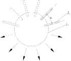
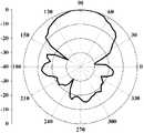
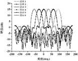
图1为本发明介质透镜天线的结构主视图,图2为图1的后视图,图3为多波束透镜天线阵列的结构示意图(图中箭头代表波束,沿介质透镜球1的球面逆时针方向依次为第一至第六波束),图4为具体实施方式八的天线反射系数的测试结果;图5为2.1GHz时的具体实施方式八的E面方向图的实验结果;图6为2.1GHz时的具体实施方式八的H面方向图的实验结果,图7为具体实施方式七的H面方向图的仿真结果。Fig. 1 is the structure front view of dielectric lens antenna of the present invention, Fig. 2 is the back view of Fig. 1, Fig. 3 is the structural representation of multi-beam lens antenna array (arrow represents wave beam among the figure, along the spherical surface counterclockwise direction of
具体实施方式Detailed ways
具体实施方式一:结合图1说明本实施方式,本实施方式的天线包括介质透镜球1和至少一个八木天线单元,每个八木天线单元包括介质板2、引向器3、两个有源振子4、两个反射器5、第一用于馈电的平衡微带线6和第二用于馈电的平衡微带线7,八木天线单元的介质板2沿介质透镜球1的法线方向设置在介质透镜球1上且二者连接并制成一体,引向器3、两个有源振子4、两个反射器5、第一用于馈电的平衡微带线6均设在介质板2的前侧壁上,第二用于馈电的平衡微带线7为L形,第二用于馈电的平衡微带线7设在介质板2的后侧壁上,第一用于馈电的平衡微带线6的一端与两个有源振子4中的一个连接,第一用于馈电的平衡微带线6的另一端同时连接两个反射器5,介质板2上开有通孔2-1,通孔2-1内设有金属填充物8(该金属填充物8为焊锡),第二用于馈电的平衡微带线7的水平段通过金属填充物8与两个有源振子4剩余的一个连接。Specific Embodiment 1: This embodiment is described in conjunction with FIG. 1. The antenna of this embodiment includes a
八木天线单元的馈电处(即第一用于馈电的平衡微带线6和第二用于馈电的平衡微带线7)使用同轴接头直接相连馈电或集成电路中的共面波导馈线直接相连馈电。The feeding place of the Yagi antenna unit (that is, the first
有源振子4可以由公式L/λ1=0.18~0.20计算得出,其中L为有源振子4的长度,λ1为天线通频带下限频率所对应的波长。The
具体实施方式二:结合图1说明本实施方式,本实施方式的介质透镜球1的相对介电常数为2.2,介质透镜球1的半径R为45mm,引向器3靠近介质透镜球1一端的端面的几何中心与介质透镜球1的球心距离为d=50mm,介质透镜球1能够汇聚电磁能量,具有提高天线增益、增强天线定向辐射特性和减小波束宽度的作用。其它实施方式与具体实施方式一相同。Specific embodiment two: this embodiment is described in conjunction with Fig. 1, the relative permittivity of the
具体实施方式三:结合图1说明本实施方式,本实施方式的介质板2为FR-4环氧玻璃布层压板,介质板2的相对介电常数为4.4,介质板2的厚度为1.5mm,八木天线单元采用印刷介质板形式,重量轻、体积小、易于加工。其它实施方式与具体实施方式一或二相同。Specific embodiment three: this embodiment is described in conjunction with Fig. 1, the
具体实施方式四:结合图1说明本实施方式,本实施方式的每个反射器5的长度Lr为有源振子4的长度L的1-1.1倍,引向器3的长度Ld为两个有源振子4总长2L的55%-65%。此结构用于调整八木天线单元的阻抗带宽,引向器3从有源振子4处耦合能量,反射器5从有源振子4处耦合能量,对八木天线的阻抗及方向性产生影响。其它实施方式与具体实施方式三相同。Specific Embodiment Four: This embodiment is described in conjunction with Fig. 1, the length Lr of each
具体实施方式五:结合图1说明本实施方式,本实施方式的有源振子4的长度为L=32mm,宽度为w=7mm,引向器3和反射器5与有源振子4的中心距离分别为Sd=10mm和Sr=19mm,该结构利于引向器和反射器通过有源振子耦合能量,可以实现宽频带和较强的定向辐射特性。其它实施方式与具体实施方式四相同。Specific Embodiment Five: This embodiment is described in conjunction with FIG. 1. The length of the
具体实施方式六:结合图1说明本实施方式,本实施方式的两个有源振子4之间的距离为g=0.3mm,两个有源振子4之间的距离可以调整天线的阻抗带宽,g的取值不超过2mm。其它实施方式与具体实施方式五相同。Specific embodiment six: this embodiment is described in conjunction with Fig. 1, the distance between the two
具体实施方式七:结合图3说明本实施方式,本实施方式的八木天线单元的数量为六个,六个八木天线单元的介质板2均布装在介质透镜球1的球面上,每个介质板2沿介质透镜球1的法线方向设置,位于介质透镜球1两侧的两个介质板2之间的角度为150°,两个八木天线单元之间的角度α=30°,引向器3靠近介质透镜球1一端的端面的几何中心与介质透镜球1的球心距离为d=125mm、介质透镜球1的半径R=120mm、引向器3靠近介质透镜球1一端的端面的几何中心与介质透镜球1形成的圆锥的锥角θ=87.6°,这样可以形成多波束介质透镜天线阵列,该天线可以通过安装电子开关实现多波束的切换功能,具有宽角度的扫描特性,其它实施方式与具体实施方式一相同。Specific embodiment seven: illustrate this embodiment in conjunction with Fig. 3, the quantity of the Yagi antenna unit of this embodiment is six, and the
具体实施方式八:结合图1说明本实施方式,本实施方式的八木天线单元的数量为1个,有源振子4的长度L=32mm,有源振子4的宽度w=7mm,引向器3的长度Ld=39mm,引向器3的宽度wd=7mm,反射器5的长度Lr=35mm,反射器5的宽度wr=7mm,引向器3和有源振子4的中心距离Sd=10mm,反射器5和有源振子4的中心距离Sr=19mm,通孔2-1的半径r=0.5mm,第一用于馈电的平衡微带线6和第二用于馈电的平衡微带线7的长度Lf=26.25mm,第一用于馈电的平衡微带线6和第二用于馈电的平衡微带线7的宽度wf=3mm,两个有源振子4之间的距离为g=0.3mm,第二用于馈电的平衡微带线7的竖直段与通孔2-1的中心距离x=8mm,介质板1的长度Ls=78mm,介质板1的宽度Ws=40mm,引向器3靠近介质透镜球1一端的端面的几何中心与介质球的球心距离为d=50mm,介质透镜球的半径R=45mm,引向器3靠近介质透镜球1一端的端面的几何中心与介质球形成的圆锥的锥角θ=84°。Specific embodiment eight: illustrate this embodiment in conjunction with Fig. 1, the quantity of the Yagi antenna unit of this embodiment is 1, the length L=32mm of
根据具体实施方式八要求尺寸制作了天线的实物并进行了测试。反射系数测试结果如图4所示,天线在1.77~2.44GHz的频带内反射系数低于-10dB,相对带宽为31.8%,1.90~2.35GHz频段的反射系数低于-15dB(相对带宽为21.2%),能够覆盖高空平台通信系统工作的频段。According to the required dimensions of the eighth embodiment, the actual antenna was fabricated and tested. The reflection coefficient test results are shown in Figure 4. The reflection coefficient of the antenna in the 1.77-2.44GHz frequency band is lower than -10dB, and the relative bandwidth is 31.8%. ), which can cover the frequency band where the high-altitude platform communication system works.
图5和图6为具体实施方式八天线方向图的测试结果,由图5和图6可以看出:介质透镜天线具有良好的定向辐射特性,在2.1GHz处E面的波束宽度为58°,H面的波束宽度为64°,采用比较法测试了该天线的增益为9.3dBi。透镜天线的E面和H面波束宽度相差不大,可以形成近似旋转对称的波束,对于高空平台覆盖地面的蜂窝小区是十分有益的。图7为具体实施方式七多波束透镜天线阵列的H面方向图的仿真结果,表明设计的多波束透镜天线阵列在2.1GHz的波束宽度为27.5°、旁瓣电平为-14.4dB,增益为15.2dBi,从图中可以看出,天线的3dB波束实现了无缝的覆盖,即在蜂窝小区的边缘天线的链路增益最大也可以达到15dB。由于只放置了一排天线,所以多波束天线可以覆盖的角域为177°×29.1°。该天线可以通过安装电子开关实现多波束的切换功能,具有宽角度的扫描特性。Fig. 5 and Fig. 6 are the test results of the eight-antenna pattern of the specific embodiment. It can be seen from Fig. 5 and Fig. 6 that the dielectric lens antenna has good directional radiation characteristics, and the beam width of the E plane at 2.1 GHz is 58°. The beam width of the H plane is 64°, and the gain of the antenna is 9.3dBi tested by the comparison method. The beam widths of the E plane and the H plane of the lens antenna are not much different, and can form approximately rotationally symmetrical beams, which is very beneficial for the high-altitude platform covering the ground cell. Fig. 7 is the simulation result of the H plane pattern of seven multi-beam lens antenna arrays of the specific embodiment, shows that the beam width of the multi-beam lens antenna array of design is 27.5 °, the side lobe level is-14.4dB at 2.1GHz, and the gain is 15.2dBi. It can be seen from the figure that the 3dB beam of the antenna achieves seamless coverage, that is, the maximum link gain of the antenna at the edge of the cell can reach 15dB. Since only one row of antennas is placed, the angular domain that the multi-beam antenna can cover is 177°×29.1°. The antenna can realize multi-beam switching function by installing an electronic switch, and has wide-angle scanning characteristics.
工作原理:该天线的引向器3和有源振子4均为金属细带条,这是一种谐振式结构,当第一用于馈电的平衡微带线6和第二用于馈电的平衡微带线7分别连接同轴接头的内外芯时,可以实现对天线的两个有源振子4馈电,在有源振子4上的激励电流通过空间电磁场分布在引向器3上产生感应电流,共同向自由空间辐射,再通过介质透镜球1汇聚电磁能量。因此,该介质透镜天线具有宽频带、高增益、定向辐射特性强和波束宽度窄特点。Working principle: The
Claims (7)
Translated fromChinesePriority Applications (1)
| Application Number | Priority Date | Filing Date | Title |
|---|---|---|---|
| CN2012101050418ACN102610926A (en) | 2012-04-11 | 2012-04-11 | Dielectric lens antenna for high-altitude platform communication system |
Applications Claiming Priority (1)
| Application Number | Priority Date | Filing Date | Title |
|---|---|---|---|
| CN2012101050418ACN102610926A (en) | 2012-04-11 | 2012-04-11 | Dielectric lens antenna for high-altitude platform communication system |
Publications (1)
| Publication Number | Publication Date |
|---|---|
| CN102610926Atrue CN102610926A (en) | 2012-07-25 |
Family
ID=46528160
Family Applications (1)
| Application Number | Title | Priority Date | Filing Date |
|---|---|---|---|
| CN2012101050418APendingCN102610926A (en) | 2012-04-11 | 2012-04-11 | Dielectric lens antenna for high-altitude platform communication system |
Country Status (1)
| Country | Link |
|---|---|
| CN (1) | CN102610926A (en) |
Cited By (12)
| Publication number | Priority date | Publication date | Assignee | Title |
|---|---|---|---|---|
| CN102800951A (en)* | 2012-08-06 | 2012-11-28 | 哈尔滨工业大学 | Printed Yagi antenna of vibrator loading type balance microstrip line feed |
| CN103531889A (en)* | 2013-09-30 | 2014-01-22 | 西安电子科技大学 | Small-sized broadband end-on-fire antenna |
| CN104617383A (en)* | 2015-01-23 | 2015-05-13 | 西北工业大学 | Multi-beam scanning lens antenna |
| WO2018010443A1 (en)* | 2016-07-14 | 2018-01-18 | 华为技术有限公司 | Dielectric lens and splitting antenna |
| CN108736171A (en)* | 2018-05-18 | 2018-11-02 | 成都泰格微波技术股份有限公司 | A kind of wide-angle scanning multibeam lens antenna |
| CN109546359A (en)* | 2018-12-06 | 2019-03-29 | 北京神舟博远科技有限公司 | A kind of directional diagram reconstructable phased array antenna system based on 3D printing |
| CN112002989A (en)* | 2020-08-27 | 2020-11-27 | 宁波大学 | On-chip antenna based on glass through hole array |
| CN112703639A (en)* | 2018-09-11 | 2021-04-23 | 罗杰斯公司 | Dielectric resonator antenna system |
| CN113497328A (en)* | 2020-04-03 | 2021-10-12 | 深圳市威富通讯技术有限公司 | Radio frequency front-end device of three-dimensional high-gain antenna |
| CN113555665A (en)* | 2020-04-08 | 2021-10-26 | 深圳市威富通讯技术有限公司 | Multi-channel high-gain WIFI (Wireless Fidelity) transceiver |
| CN114509131A (en)* | 2020-11-16 | 2022-05-17 | 智能雷达系统有限公司 | RADAR liquid level metering device |
| CN117175220A (en)* | 2023-11-01 | 2023-12-05 | 广东工业大学 | Long Bo lens antenna with continuously gradual-changed holes |
Citations (2)
| Publication number | Priority date | Publication date | Assignee | Title |
|---|---|---|---|---|
| US20020003505A1 (en)* | 1999-11-18 | 2002-01-10 | Ebling James Paul | Multi-beam antenna |
| CN1836352A (en)* | 2003-08-12 | 2006-09-20 | 汽车系统实验室公司 | Multi-beam antenna |
- 2012
- 2012-04-11CNCN2012101050418Apatent/CN102610926A/enactivePending
Patent Citations (2)
| Publication number | Priority date | Publication date | Assignee | Title |
|---|---|---|---|---|
| US20020003505A1 (en)* | 1999-11-18 | 2002-01-10 | Ebling James Paul | Multi-beam antenna |
| CN1836352A (en)* | 2003-08-12 | 2006-09-20 | 汽车系统实验室公司 | Multi-beam antenna |
Non-Patent Citations (1)
| Title |
|---|
| 蔡润南 等: "具有梯形有源振子的印刷引向天线研究", 《微波学报》* |
Cited By (17)
| Publication number | Priority date | Publication date | Assignee | Title |
|---|---|---|---|---|
| CN102800951A (en)* | 2012-08-06 | 2012-11-28 | 哈尔滨工业大学 | Printed Yagi antenna of vibrator loading type balance microstrip line feed |
| CN103531889A (en)* | 2013-09-30 | 2014-01-22 | 西安电子科技大学 | Small-sized broadband end-on-fire antenna |
| CN103531889B (en)* | 2013-09-30 | 2015-07-15 | 西安电子科技大学 | Small-sized broadband end-on-fire antenna |
| CN104617383A (en)* | 2015-01-23 | 2015-05-13 | 西北工业大学 | Multi-beam scanning lens antenna |
| WO2018010443A1 (en)* | 2016-07-14 | 2018-01-18 | 华为技术有限公司 | Dielectric lens and splitting antenna |
| US11139583B2 (en) | 2016-07-14 | 2021-10-05 | Huawei Technologies Co., Ltd. | Dielectric lens and multi-beam antenna |
| CN108736171A (en)* | 2018-05-18 | 2018-11-02 | 成都泰格微波技术股份有限公司 | A kind of wide-angle scanning multibeam lens antenna |
| CN112703639A (en)* | 2018-09-11 | 2021-04-23 | 罗杰斯公司 | Dielectric resonator antenna system |
| CN109546359A (en)* | 2018-12-06 | 2019-03-29 | 北京神舟博远科技有限公司 | A kind of directional diagram reconstructable phased array antenna system based on 3D printing |
| CN109546359B (en)* | 2018-12-06 | 2023-08-22 | 北京神舟博远科技有限公司 | Directional diagram reconfigurable phased array antenna system based on 3D printing |
| CN113497328A (en)* | 2020-04-03 | 2021-10-12 | 深圳市威富通讯技术有限公司 | Radio frequency front-end device of three-dimensional high-gain antenna |
| CN113555665A (en)* | 2020-04-08 | 2021-10-26 | 深圳市威富通讯技术有限公司 | Multi-channel high-gain WIFI (Wireless Fidelity) transceiver |
| CN112002989A (en)* | 2020-08-27 | 2020-11-27 | 宁波大学 | On-chip antenna based on glass through hole array |
| CN112002989B (en)* | 2020-08-27 | 2023-02-10 | 宁波大学 | An On-Chip Antenna Based on Through-Glass Hole Array |
| CN114509131A (en)* | 2020-11-16 | 2022-05-17 | 智能雷达系统有限公司 | RADAR liquid level metering device |
| CN117175220A (en)* | 2023-11-01 | 2023-12-05 | 广东工业大学 | Long Bo lens antenna with continuously gradual-changed holes |
| CN117175220B (en)* | 2023-11-01 | 2024-01-26 | 广东工业大学 | A Longbo lens antenna with continuous gradient openings |
Similar Documents
| Publication | Publication Date | Title |
|---|---|---|
| CN102610926A (en) | Dielectric lens antenna for high-altitude platform communication system | |
| EP2406852B1 (en) | High gain metamaterial antenna device | |
| CN107369895B (en) | A Directional High Gain Microstrip Antenna | |
| US11201394B2 (en) | Antenna device and electronic device | |
| CN107978858B (en) | Pattern reconfigurable antenna working in 60GHz frequency band | |
| CN107658568A (en) | Dual-band and dual-polarization Shared aperture waveguide trumpet planar array antenna | |
| CN112038763A (en) | High-Gain and High-Directivity Metamaterial Microstrip Antenna Based on Double Hexagonal Ring Structure | |
| CN207559068U (en) | Low Gain Low Sidelobe Micro Base Station Antenna | |
| WO2019223318A1 (en) | Indoor base station and pifa antenna thereof | |
| CN109462028B (en) | A radio frequency microelectromechanical microstrip antenna | |
| WO2019080547A1 (en) | Microstrip radiation unit and antenna for use in 5g system | |
| CN210074169U (en) | Rectangular microstrip series-fed antenna based on grounded coplanar waveguide | |
| CN114899612A (en) | Circularly polarized airborne detection antenna based on double-row periodic arrangement | |
| Upadhyay et al. | Design of microstrip patch antenna array for WLAN application | |
| CN103401068B (en) | High-gain wideband stereoscopic slot Yagi antenna | |
| CN211455960U (en) | High-gain radio frequency front-end device | |
| CN103594806B (en) | Thin substrate amplitude correction slot-line planar horn antenna | |
| CN117977197A (en) | Low-profile phased array antenna for ultra-wideband and ultra-wide angle scanning | |
| CN115173029B (en) | A wide beam circularly polarized microstrip array element suitable for AOP millimeter wave phased array | |
| CN107732440B (en) | Ultra-wideband high-gain beam upward-tilting omnidirectional antenna | |
| CN116937182A (en) | A modular millimeter wave array antenna | |
| CN103594780B (en) | an antenna | |
| CN103594819B (en) | Thin substrate phase amplitude corrects broadband planar horn antenna | |
| Jaiswal et al. | 60 GHz recessed ground plane microstrip patch antenna array with improved bandwidth and gain | |
| TWI464962B (en) | Hybrid multi-antenna system and wireless communication apparatus using the same |
Legal Events
| Date | Code | Title | Description |
|---|---|---|---|
| C06 | Publication | ||
| PB01 | Publication | ||
| C10 | Entry into substantive examination | ||
| SE01 | Entry into force of request for substantive examination | ||
| C02 | Deemed withdrawal of patent application after publication (patent law 2001) | ||
| WD01 | Invention patent application deemed withdrawn after publication | Application publication date:20120725 |