CN102607738A - Intake temperature sensor - Google Patents
Intake temperature sensorDownload PDFInfo
- Publication number
- CN102607738A CN102607738ACN201110442664XACN201110442664ACN102607738ACN 102607738 ACN102607738 ACN 102607738ACN 201110442664X ACN201110442664X ACN 201110442664XACN 201110442664 ACN201110442664 ACN 201110442664ACN 102607738 ACN102607738 ACN 102607738A
- Authority
- CN
- China
- Prior art keywords
- intake air
- air temperature
- temperature sensor
- detection element
- temperature detection
- Prior art date
- Legal status (The legal status is an assumption and is not a legal conclusion. Google has not performed a legal analysis and makes no representation as to the accuracy of the status listed.)
- Granted
Links
- 238000001514detection methodMethods0.000claimsabstractdescription94
- 229910052751metalInorganic materials0.000claimsdescription23
- 239000002184metalSubstances0.000claimsdescription23
- 230000017525heat dissipationEffects0.000claimsdescription21
- 239000000758substrateSubstances0.000claimsdescription13
- 239000000919ceramicSubstances0.000claimsdescription7
- 239000000463materialSubstances0.000claimsdescription7
- 229920005989resinPolymers0.000claimsdescription6
- 239000011347resinSubstances0.000claimsdescription6
- 239000004734Polyphenylene sulfideSubstances0.000claimsdescription3
- 239000004033plasticSubstances0.000claimsdescription3
- -1polybutylene terephthalatePolymers0.000claimsdescription3
- 229920001707polybutylene terephthalatePolymers0.000claimsdescription3
- 229920000069polyphenylene sulfidePolymers0.000claimsdescription3
- 238000001816coolingMethods0.000abstractdescription5
- 229910000679solderInorganic materials0.000description10
- 238000010438heat treatmentMethods0.000description7
- 238000010586diagramMethods0.000description5
- 238000009434installationMethods0.000description4
- 230000008859changeEffects0.000description3
- 230000000694effectsEffects0.000description3
- 239000011521glassSubstances0.000description3
- 239000011248coating agentSubstances0.000description2
- 238000000576coating methodMethods0.000description2
- 230000007423decreaseEffects0.000description2
- 238000000034methodMethods0.000description2
- BASFCYQUMIYNBI-UHFFFAOYSA-NplatinumChemical compound[Pt]BASFCYQUMIYNBI-UHFFFAOYSA-N0.000description2
- 230000009467reductionEffects0.000description2
- 230000004043responsivenessEffects0.000description2
- 239000000853adhesiveSubstances0.000description1
- 230000001070adhesive effectEffects0.000description1
- 230000005540biological transmissionEffects0.000description1
- 239000003822epoxy resinSubstances0.000description1
- 239000000446fuelSubstances0.000description1
- 230000003434inspiratory effectEffects0.000description1
- 238000004519manufacturing processMethods0.000description1
- 238000005259measurementMethods0.000description1
- 230000004048modificationEffects0.000description1
- 238000012986modificationMethods0.000description1
- 229910052697platinumInorganic materials0.000description1
- 229920003217poly(methylsilsesquioxane)Polymers0.000description1
- 229920000647polyepoxidePolymers0.000description1
- 230000005855radiationEffects0.000description1
- 230000004044responseEffects0.000description1
- 238000005476solderingMethods0.000description1
- 238000005496temperingMethods0.000description1
- 238000011144upstream manufacturingMethods0.000description1
Images


Classifications
- G—PHYSICS
- G01—MEASURING; TESTING
- G01K—MEASURING TEMPERATURE; MEASURING QUANTITY OF HEAT; THERMALLY-SENSITIVE ELEMENTS NOT OTHERWISE PROVIDED FOR
- G01K13/00—Thermometers specially adapted for specific purposes
- G01K13/02—Thermometers specially adapted for specific purposes for measuring temperature of moving fluids or granular materials capable of flow
- G—PHYSICS
- G01—MEASURING; TESTING
- G01F—MEASURING VOLUME, VOLUME FLOW, MASS FLOW OR LIQUID LEVEL; METERING BY VOLUME
- G01F1/00—Measuring the volume flow or mass flow of fluid or fluent solid material wherein the fluid passes through a meter in a continuous flow
- G01F1/68—Measuring the volume flow or mass flow of fluid or fluent solid material wherein the fluid passes through a meter in a continuous flow by using thermal effects
- G01F1/684—Structural arrangements; Mounting of elements, e.g. in relation to fluid flow
- G01F1/6842—Structural arrangements; Mounting of elements, e.g. in relation to fluid flow with means for influencing the fluid flow
- G—PHYSICS
- G01—MEASURING; TESTING
- G01F—MEASURING VOLUME, VOLUME FLOW, MASS FLOW OR LIQUID LEVEL; METERING BY VOLUME
- G01F15/00—Details of, or accessories for, apparatus of groups G01F1/00 - G01F13/00 insofar as such details or appliances are not adapted to particular types of such apparatus
- G01F15/18—Supports or connecting means for meters
- G01F15/185—Connecting means, e.g. bypass conduits
- G—PHYSICS
- G01—MEASURING; TESTING
- G01F—MEASURING VOLUME, VOLUME FLOW, MASS FLOW OR LIQUID LEVEL; METERING BY VOLUME
- G01F5/00—Measuring a proportion of the volume flow
- G—PHYSICS
- G01—MEASURING; TESTING
- G01K—MEASURING TEMPERATURE; MEASURING QUANTITY OF HEAT; THERMALLY-SENSITIVE ELEMENTS NOT OTHERWISE PROVIDED FOR
- G01K1/00—Details of thermometers not specially adapted for particular types of thermometer
- G01K1/16—Special arrangements for conducting heat from the object to the sensitive element
- G—PHYSICS
- G01—MEASURING; TESTING
- G01K—MEASURING TEMPERATURE; MEASURING QUANTITY OF HEAT; THERMALLY-SENSITIVE ELEMENTS NOT OTHERWISE PROVIDED FOR
- G01K2205/00—Application of thermometers in motors, e.g. of a vehicle
- G01K2205/02—Application of thermometers in motors, e.g. of a vehicle for measuring inlet gas temperature
Landscapes
- Physics & Mathematics (AREA)
- General Physics & Mathematics (AREA)
- Fluid Mechanics (AREA)
- Measuring Volume Flow (AREA)
- Measuring Temperature Or Quantity Of Heat (AREA)
Abstract
Translated fromChinese
Description
Translated fromChinese技术领域technical field
本发明涉及吸气温度传感器,尤其涉及低流量下的测定精度高且响应性良好的吸气温度传感器。The present invention relates to an intake air temperature sensor, and more particularly, to an intake air temperature sensor with high measurement accuracy and good responsiveness at low flow rates.
背景技术Background technique
关于对吸气管内的吸气温度进行检测的现有的吸气温度传感器,存在专利文献1中记载的流量测定装置和专利文献2中记载的热式空气流量计等。As conventional intake air temperature sensors that detect the intake air temperature in the intake pipe, there are a flow measuring device described in Patent Document 1, a thermal air flow meter described in
【专利文献1】日本特开2009-8619号公报[Patent Document 1] Japanese Patent Laid-Open No. 2009-8619
【专利文献2】WO02/010694号公报[Patent Document 2] WO02/010694 Publication
在专利文献1中,利用金属端子使吸气温度检测元件直接露出到吸气流中。In Patent Document 1, the intake air temperature detection element is directly exposed to the intake air flow by using a metal terminal.
但是,对于吸气流量成为低流量的情况欠缺考虑。最近的机动车发动机为了实现低燃料消耗率而意图实现空转的低转速化。因此,吸气流量的低流量化不断得到发展。当吸气流量成为低流量时,从吸气温度检测元件的表面向吸气流的热阻急剧变高。其结果是,来自安装部的热量或电路的自身发热经过金属端子而使吸气温度检测元件的温度变化。因此,在吸气温度检测元件的温度与吸气温度之间产生差异,从而无法正确地检测出吸气温度。另外,当从吸气温度检测元件的表面向吸气流的热阻变高时,因吸气温度检测元件自身的热容量而产生的热时间常数达到几十秒,从而吸气温度的检测延迟变大。However, consideration is not given to the case where the inhalation flow rate becomes a low flow rate. In order to achieve low fuel consumption, recent motor vehicle engines are intended to reduce the rotational speed of idling. Therefore, the reduction of the inhalation flow rate has been continuously developed. When the intake air flow rate becomes low, the thermal resistance from the surface of the intake air temperature detection element to the intake air flow rapidly increases. As a result, heat from the mounting portion or self-heating of the circuit changes the temperature of the intake air temperature detection element via the metal terminal. Therefore, a difference occurs between the temperature of the intake air temperature detecting element and the intake air temperature, and the intake air temperature cannot be accurately detected. In addition, when the thermal resistance from the surface of the intake air temperature detection element to the intake air flow becomes high, the thermal time constant due to the heat capacity of the intake air temperature detection element itself reaches several tens of seconds, and the detection delay of the intake air temperature decreases. big.
在专利文献2中,在副通路内配置吸气温度检测元件,且将流量检测元件和吸气温度检测元件配置在同一电路基板上。但是,副通路结构体因来自安装部的热量和电路的自身发热而成为温度与吸气流不同的温度。尤其是在低流量时,该倾向变强。因此,副通路内的空气的温度受到来自副通路结构体的热影响而发生变化,成为温度与被测定空气流不同的温度。另外,由于在副通路内部配置吸气温度检测元件,因此吸气温度检测元件对副通路内的空气流的温度进行检测。由此,吸气温度检测元件的输出产生误差。In
并且,由于副通路结构体的温度变化受到框体的热时间常数的影响,因此副通路结构体的温度到稳定为止需要几十秒至几分钟的时间。因此,在上述技术中,吸气温度在从变化开始几十秒至几分钟的时间内,吸气温度传感器的输出变得不正确。另外,电路基板采用玻璃·环氧树脂这样的热阻高的材料。因此,来自驱动电路的自身发热的影响能够降低,但是对于向空气流的热阻的降低则欠缺考虑,低流量下的吸气温度检测元件的热时间常数达到几十秒,从而吸气温度的检测延迟变大。In addition, since the temperature change of the sub-via structure is affected by the thermal time constant of the frame, it takes several tens of seconds to several minutes for the temperature of the sub-via structure to stabilize. Therefore, in the technique described above, the output of the intake air temperature sensor becomes incorrect within several tens of seconds to several minutes from the start of the change in the intake air temperature. In addition, a material with high thermal resistance such as glass and epoxy resin is used for the circuit board. Therefore, the influence of self-heating from the drive circuit can be reduced, but the reduction of the thermal resistance to the air flow is not considered. The thermal time constant of the intake air temperature detection element reaches tens of seconds at a low flow rate, so that the intake air temperature The detection delay becomes larger.
发明内容Contents of the invention
因此,本发明鉴于上述情况而提出,其目的在于提供一种即使在低流量区域也能快速且正确地检测出吸气温度的吸气温度传感器。Therefore, the present invention has been made in view of the above circumstances, and an object of the present invention is to provide an intake air temperature sensor capable of quickly and accurately detecting an intake air temperature even in a low flow area.
为了解决上述课题,通过在直接暴露于吸气管内的吸气流中的散热板上固定温度检测元件并基于从本温度检测元件得到的输出而输出吸气温度来实现。In order to solve the above-mentioned problems, it is realized by fixing a temperature detection element on a heat sink directly exposed to the intake air flow in the intake pipe, and outputting the intake air temperature based on the output obtained from the temperature detection element.
【发明效果】【Invention effect】
根据本发明,能够减少吸气温度检测元件向吸气流的热阻,因此能够提供一种可以改善低流量下的吸气温度的检测精度且具有快速响应性的吸气温度传感器。According to the present invention, since the thermal resistance of the intake air temperature detection element to the intake air flow can be reduced, it is possible to provide an intake air temperature sensor capable of improving the detection accuracy of the intake air temperature at a low flow rate and having a quick response.
附图说明Description of drawings
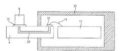
图1是表示将第一实施例的吸气温度传感器安装于吸气管的状态的安装图。FIG. 1 is an installation diagram showing a state in which an intake air temperature sensor of a first embodiment is attached to an intake pipe.
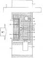
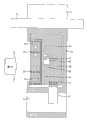
图2是图1中的A-A′的剖视图。Fig. 2 is a cross-sectional view of A-A' in Fig. 1 .
图3是第一实施例的吸气温度传感器的立体图。Fig. 3 is a perspective view of the intake air temperature sensor of the first embodiment.
图4是表示第一实施例的热等效电路的图。FIG. 4 is a diagram showing a thermal equivalent circuit of the first embodiment.
图5是表示吸气温度检测元件6的误差特性的图。FIG. 5 is a graph showing error characteristics of the intake air
图6是第二实施例的吸气温度传感器的图1的A-A′线的剖视图。Fig. 6 is a cross-sectional view taken along line A-A' of Fig. 1 of the intake air temperature sensor of the second embodiment.
图7是图6的B-B′线的剖视图。Fig. 7 is a sectional view taken along line B-B' of Fig. 6 .
图8是第二实施例的变形例的图6的B-B′线的剖视图。Fig. 8 is a cross-sectional view taken along line B-B' of Fig. 6 according to a modified example of the second embodiment.
图9是第二实施例的变形例的图6的B-B′线的剖视图。Fig. 9 is a cross-sectional view taken along line B-B' of Fig. 6 according to a modified example of the second embodiment.
图10是第三实施例的吸气温度传感器的图1的A-A′线的剖视图。Fig. 10 is a sectional view taken along line A-A' of Fig. 1 of the intake air temperature sensor of the third embodiment.
图11是第四实施例的吸气温度传感器的图1的A-A′线的剖视图。Fig. 11 is a sectional view taken along line A-A' of Fig. 1 of an intake air temperature sensor of a fourth embodiment.
图12是第五实施例的吸气温度传感器的图1的A-A′线的剖视图。Fig. 12 is a sectional view taken along line A-A' of Fig. 1 of an intake air temperature sensor of a fifth embodiment.
图13是第六实施例的吸气温度传感器的图1的A-A′线的剖视图。Fig. 13 is a sectional view taken along line A-A' of Fig. 1 of an intake air temperature sensor of a sixth embodiment.
图14是第七实施例的吸气温度传感器的图1的A-A′线的剖视图。Fig. 14 is a sectional view taken along line A-A' of Fig. 1 of an intake air temperature sensor of a seventh embodiment.
图15是第八实施例的吸气温度传感器的图1的A-A′线的剖视图。Fig. 15 is a sectional view taken along line A-A' of Fig. 1 of an intake air temperature sensor of an eighth embodiment.
图16是第九实施例的吸气温度传感器的图1的A-A′线的剖视图。Fig. 16 is a sectional view taken along line A-A' of Fig. 1 of an intake air temperature sensor of a ninth embodiment.
图17是第十实施例的吸气温度传感器的图1的A-A′线的剖视图。Fig. 17 is a cross-sectional view taken along line A-A' of Fig. 1 of the intake air temperature sensor of the tenth embodiment.
【符号说明】【Symbol Description】
1 连接部1 connection part
2 安装部2 Installation department
3 吸气管3 suction pipe
4 散热板4 heat sink
5、7 引线5, 7 leads
6、26、38、50 吸气温度检测元件6, 26, 38, 50 Suction temperature detection element
8 副通路8 secondary channels
9 吸气温度传感器9 Suction temperature sensor
10、42、52 集成电路10, 42, 52 integrated circuits
11 电路基板11 Circuit board
12、19、20、25、27、46、47、54 金属线12, 19, 20, 25, 27, 46, 47, 54 metal wire
13 流量检测元件13 flow detection element
14、17、29、31、32、33、34、35、36、40、49 狭缝14, 17, 29, 31, 32, 33, 34, 35, 36, 40, 49 slots
15、16、18、21、37、39 焊料焊盘15, 16, 18, 21, 37, 39 Solder pads
22、55 框体22, 55 frame
23 内层配线图案23 Inner layer wiring pattern
24、28 焊盘24, 28 Pads
30 基板30 substrates
41、51 温度传感器41, 51 temperature sensor
43、45 金属板43, 45 metal plate
44、48 热敏电阻44, 48 Thermistor
53 引线框53 lead frame
具体实施方式Detailed ways
以下,依照附图,对本发明的实施例进行说明。Hereinafter, embodiments of the present invention will be described with reference to the drawings.
首先,利用图1至图5,对作为本发明的第一实施例的吸气温度传感器9进行说明。需要说明的是,图1是表示将第一实施例的吸气温度传感器9安装于吸气管3的状态的安装图,图2是图1的A-A′线的剖视图,图3是第一实施例的吸气温度传感器9的立体图,图4是表示第一实施例的热等效电路的图,图5是表示吸气温度检测元件6的误差特性的图。First, an intake
如图1所示,本发明的第一实施例的吸气温度传感器9以插入到设在吸气管3上的开口部中的形式安装,吸气温度传感器9通过安装部2固定在吸气管3上。另外,从吸气温度传感器9的电连接经由连接部1进行。另外,在吸气温度传感器9中设有副通路8,在副通路8的内部配置有流量检测元件13,该流量检测元件13能够测定在吸气管3中流动的流量。另外,散热板4以从吸气温度传感器9的框体向外部露出的方式固定,散热板4配置成直接暴露于吸气管内的吸气流中。吸气温度检测元件6配置在副通路8的外部且相对于电路基板11配置在吸气流的上游侧,该吸气温度检测元件6通过热传导性高的粘接剂等机械性地固定在散热板4上而与散热板4热结合。另外,吸气温度检测元件6经由引线5、7向吸气温度传感器9的框体22内部进行电连接。另外,在框体22内部配置电路基板11,在电路基板11上配置有用于处理吸气温度检测元件6及流量检测元件13的输出信号的集成电路10。需要说明的是,流量检测元件13通过金属线12与电路基板11连接。As shown in FIG. 1 , the intake
吸气温度检测元件6可以由热敏电阻、铂电阻体、热电偶、温度系数大的电阻等构成。尤其是通过利用厚膜印刷电阻作为吸气温度检测元件6,能够减少吸气温度检测元件6自身的热容量,从而能够实现响应性的提高。另外,为了提高向空气的散热效果,优选散热板4由金属或陶瓷等热传导率高的材料构成。由此,散热板4的温度变得均等,从而能够增大有效散热面积。需要说明的是,优选散热板4的热传导率至少为1W/m·k以上。另外,优选吸气温度传感器9的框体22由塑料、聚对苯二甲酸丁二酯树脂、聚苯硫醚树脂等热传导率小的材料构成。由此,能够降低从散热板4与框体22的粘接部的热传导。The intake air
在本实施例中,通过将吸气温度检测元件6固定于散热板4而将吸气温度检测元件6和散热板4热结合,从而能够增加向吸气流的散热面积,减小向吸气流的热阻。In this embodiment, by fixing the intake air
本实施例的吸气温度传感器9的热等效电路如图4所示,吸气温度检测元件6的温度因来自吸气流的热阻与来自安装部2及电路基板11的热阻的比而受到影响。因此,通减小来自吸气流的热阻并增大来自安装部2及电路基板11的热阻,从而能够使吸气流的温度和吸气温度检测元件6的温度更加一致。由于来自吸气流的热阻与流速的平方成反比例,因此在低流速时热阻急剧地增加,在低流量时误差有所增加。但是,在本实施例中,通过增加散热面积,从而能够减少来自吸气流的热阻。在实现流量到二分之一也能够应对的吸气温度传感器的情况下,由于流速成为二分之一,因此热阻变成为4倍。为了通过增加散热面积来应对该情况,至少需要4倍的面积。The thermal equivalent circuit of the intake
图5中示出因散热板4的有无而造成的吸气温度检测元件6的误差。由图5可知,当空气流量变小而成为低流量区域时误差增加,但通过设置散热板4能够减少检测误差。FIG. 5 shows the error of the intake air
另外,来自吸气流的热阻与吸气温度检测元件6自身的热容量一起产生热时间常数。该热时间常数使吸气温度的检测产生时间延迟。需要说明的是,在低流量区域,该热时间常数为几十秒,在将该吸气温度传感器使用于机动车发动机的控制的情况下,会导致控制性的恶化。但是,根据本实施例,由于能够减少向吸气流的热阻,因此能够减少热时间常数,从而能够实现吸气温度传感器的快速化。In addition, the thermal resistance from the intake air flow together with the thermal capacity of the intake air
另外,通过在散热板4上固定吸气温度检测元件6,从而实现吸气温度检测元件6的机械性保护。其结果是,即使吸气温度传感器9落下,也可防止直接对吸气温度检测元件6施加机械性冲击的情况。并且,通过在吸气温度传感器9的框体上设置凹部且在该凹部配置散热板4,从而实现散热板4的机械性保护。其结果是,即使吸气温度传感器9落下,也可防止直接对吸气温度检测元件6施加机械冲击的情况。In addition, the mechanical protection of the intake air
接着,利用图6至图9,对作为本发明的第二实施例的吸气温度传感器进行说明。需要说明的是,图6是第二实施例的吸气温度传感器的图1中的A-A′线的剖视图,图7是图6中的B-B′线的剖视图,图8、图9是第二实施例的变形例的图6中的B-B′线的剖视图。Next, an intake air temperature sensor as a second embodiment of the present invention will be described with reference to FIGS. 6 to 9 . It should be noted that Fig. 6 is a cross-sectional view of the intake air temperature sensor of the second embodiment along the line A-A' in Fig. 1, Fig. 7 is a cross-sectional view of the line B-B' in Fig. 6, and Fig. 8 and Fig. 9 are the second embodiment A cross-sectional view taken along line B-B' in FIG. 6 of a modified example of the example.
第二实施例的吸气温度传感器与第一实施例的吸气温度传感器为基本上相同的结构,但施加了以下的改良。需要说明的是,对于与先前说明的实施例结构相同的部分,使符号相同并省略其说明。The intake air temperature sensor of the second embodiment has basically the same structure as the intake air temperature sensor of the first embodiment, but the following improvements are added. It should be noted that, for parts having the same configuration as those of the previously described embodiments, the same symbols are assigned and description thereof will be omitted.
在本实施例中,散热板4使用陶瓷基板且设有狭缝14、17,并且使用芯片型的吸气温度检测元件6,利用焊料焊盘15、16将吸气温度检测元件6通过焊料固定。狭缝14相对于吸气温度检测元件6设置在安装部2侧,且狭缝14沿着散热板4的吸气流动的垂直方向的边开口。另一方面,狭缝17相对于吸气温度检测元件6设置在副通路8侧,且狭缝17沿着散热板4的吸气流动的垂直方向的边开口。并且,狭缝14、17以沿着吸气流动的方式并列配置有多条。焊料焊盘15如图7所示那样经由内层配线图案23连接到吸气温度传感器9的框体22的内部的焊料焊盘18,并经由金属线19向电路基板11电连接。同样,焊料焊盘16也经由内层配线图案连接到框体22的内部的焊料焊盘21,并经由金属线20向电路基板11电连接。In this embodiment, the
在本实施例中,由于能够利用热传导率高的焊料将吸气温度检测元件6向散热板4固定,因此能够使吸气温度检测元件6与散热板4的热结合良好。另外,由于能够利用内层配线图案23使配线在框体22的内部通过,因此与第一实施例那样利用引线5、7的情况相比,能够进一步提高框体内部的机密性。另外,由于能够设置狭缝14、17来设置空气的通道,因此能够增加散热板4的表面积且使空气流产生紊乱,从而实现散热阻力的降低,进而能够降低从与框体22的接触部产生的热传导。需要说明的是,吸气温度检测元件6在本实施例中使用了芯片型的部件,但也可以通过印刷来制作厚膜电阻。In this embodiment, since the intake air
另外,通过如图8所示的变形例那样在框体22上设置倾斜部,使吸气流顺利地流动,从而能够抑制吸气流的流速的降低,由此能够实现降低对吸气流的热阻。In addition, by providing an inclined portion on the
另外,通过如图9所示的变形例那样在框体22上设置倾斜部,使吸气流流过狭缝14、17,从而能够使吸气的流动产生较大的紊乱,进而能够实现降低对吸气流的热阻。In addition, by providing an inclined portion on the
接着,利用图10,对作为本发明的第三实施例的吸气温度传感器进行说明。需要说明的是,图10是第三实施例的吸气温度传感器的图1中的A-A′线的剖视图。Next, an intake air temperature sensor as a third embodiment of the present invention will be described using FIG. 10 . It should be noted that FIG. 10 is a cross-sectional view taken along line A-A' in FIG. 1 of the intake air temperature sensor of the third embodiment.
第三实施例的吸气温度传感器与第二实施例的吸气温度传感器为基本上相同的结构,但施加了以下的改良。需要说明的是,对于与先前说明的实施例结构相同的部分,使其符号相同并省略其说明。The intake air temperature sensor of the third embodiment has basically the same structure as the intake air temperature sensor of the second embodiment, but the following improvements are added. It should be noted that the same symbols are assigned to the same components as those in the previously described embodiments, and their descriptions will be omitted.
在本实施例中,将吸气温度检测元件26配置在吸气温度传感器9的框体22内部,并利用焊盘24、28将吸气温度检测元件26通过焊料固定,将吸气温度检测元件26经由焊盘24、28、金属线25、27向电路基板11电连接。In this embodiment, the intake air temperature detection element 26 is disposed inside the
在本实施例中,由于能够将吸气温度检测元件26配置在框体22的内部,因此非常容易进行吸气温度检测元件26的保护。由于吸气温度传感器9配置在吸气管的内部,因此暴露于雨水混入、汽油蒸气、回火等中,从而表面保护非常重要而需要利用玻璃·涂层等,但根据本实施例,由于能够将吸气温度检测元件26配置在框体22的内部,因此能够不需要玻璃·涂层等。In this embodiment, since the intake air temperature detection element 26 can be arranged inside the
接着,利用图11对作为本发明的第四实施例的吸气温度传感器进行说明。需要说明的是,图11是第四实施例的吸气温度传感器的图1中的A-A′线的剖视图。Next, an intake air temperature sensor as a fourth embodiment of the present invention will be described with reference to FIG. 11 . It should be noted that FIG. 11 is a sectional view taken along line A-A' in FIG. 1 of the intake air temperature sensor of the fourth embodiment.
第四实施例的吸气温度传感器与第二实施例的吸气温度传感器为基本上相同的结构,但施加了以下的改良。需要说明的是,对于与先前说明的实施例结构相同的部分,使符号相同并省略其说明。The intake air temperature sensor of the fourth embodiment has basically the same structure as the intake air temperature sensor of the second embodiment, but the following improvements are added. It should be noted that, for parts having the same configuration as those of the previously described embodiments, the same symbols are assigned and description thereof will be omitted.
在本实施例中,配置有由同一构件构成散热板4和电路基板11的基板30。散热板4需要高的热传导率,电路基板11需要配线图案,而作为满足上述要求的构件,采用陶瓷基板、金属基(metal base)基板等。由此,从吸气温度检测元件6向集成电路10的配线可以不使用金属线而仅通过基板30的配线图案连接,从而能够提高接线的可靠性且实现因工时降低带来的低成本化。另外,为了避免集成电路10的自身发热对吸气温度检测元件6产生影响而设置狭缝29,从而防止来自集成电路10的发热向吸气温度检测元件6传递的情况。需要说明的是,在如本实施例那样由同一构件构成散热板4和电路基板11的情况下,优选基板30为长方形。因此,在框体22上设置凹部且在凹部上设置散热板4的结构具有以下的优点。第一,能够将基板30形成为长方形。第二,通过形成为凹形状,使吸气的导入排出顺利地流动。In the present embodiment, the
接着,利用图12对作为本发明的第五实施例的吸气温度传感器进行说明。需要说明的是,图12是第五实施例的吸气温度传感器的图1中的A-A′线的剖视图。Next, an intake air temperature sensor as a fifth embodiment of the present invention will be described with reference to FIG. 12 . It should be noted that Fig. 12 is a sectional view taken along line A-A' in Fig. 1 of the intake air temperature sensor of the fifth embodiment.
第五实施例的吸气温度传感器与第四实施例的吸气温度传感器为基本上相同的结构,但施加了以下的改良。需要说明的是,对于与先前说明的实施例结构相同的部分,使符号相同并省略其说明。The intake air temperature sensor of the fifth embodiment has basically the same structure as the intake air temperature sensor of the fourth embodiment, but the following improvements are added. It should be noted that, for parts having the same configuration as those of the previously described embodiments, the same symbols are assigned and description thereof will be omitted.
在本实施例中,将吸气温度检测元件38向框体22的内部配置,从而能够得到与第二实施例同样的效果。另外,为了避免集成电路10的自身发热对吸气温度检测元件38产生影响而设置狭缝35、36、40,从而防止来自集成电路10的发热向吸气温度检测元件38传递。尤其是狭缝36以包围吸气温度检测元件38的周围的方式设置。并且,在狭缝35、36、40之间制作出间隙,来确保配线图案通过的区域。另外,通过配置成使狭缝31在比狭缝32靠安装部2侧沿着吸气流动开口,且使狭缝34在比狭缝33靠副通路8侧沿着吸气流动开口,从而防止从基板与框体22的固定部流入热量。需要说明的是,通过狭缝32、33来降低向吸气流的散热阻力。吸气温度检测元件38通过焊料焊盘37、39而利用焊料固定。In this embodiment, the intake air temperature detection element 38 is arranged inside the
接着,利用图13对作为本发明的第六实施例的吸气温度传感器进行说明。需要说明的是,图13是第六实施例的吸气温度传感器的图1中的A-A′线的剖视图。Next, an intake air temperature sensor as a sixth embodiment of the present invention will be described with reference to FIG. 13 . It should be noted that Fig. 13 is a cross-sectional view taken along the line A-A' in Fig. 1 of the intake air temperature sensor of the sixth embodiment.
第六实施例的吸气温度传感器与第五实施例的吸气温度传感器为基本上相同的结构,但施加了以下的改良。需要说明的是,对于与先前说明的实施例结构相同的部分,使符号相同并省略其说明。The intake air temperature sensor of the sixth embodiment has basically the same structure as the intake air temperature sensor of the fifth embodiment, but the following improvements are added. It should be noted that, for parts having the same configuration as those of the previously described embodiments, the same symbols are assigned and description thereof will be omitted.
在本实施例中,代替吸气温度检测元件38而配置具有温度传感器41的集成电路42,通过温度传感器41对吸气温度进行检测。为了实现本实施例,需要将自身发热抑制得较小的集成电路42,但根据本实施例,能够取消吸气温度检测元件38,从而能够因部件件数的减少而实现低成本化。In this embodiment, an
接着,利用图14对作为本发明的第七实施例的吸气温度传感器进行说明。需要说明的是,图14是第七实施例的吸气温度传感器的图1中的A-A′线的剖视图。Next, an intake air temperature sensor as a seventh embodiment of the present invention will be described with reference to FIG. 14 . It should be noted that FIG. 14 is a cross-sectional view taken along the line A-A' in FIG. 1 of the intake air temperature sensor of the seventh embodiment.
第七实施例的吸气温度传感器与第二实施例的吸气温度传感器为基本上相同的结构,但施加了以下的改良。需要说明的是,对于与先前说明的实施例结构相同的部分,使符号相同并省略其说明。The intake air temperature sensor of the seventh embodiment has basically the same structure as the intake air temperature sensor of the second embodiment, but the following improvements are added. It should be noted that, for parts having the same configuration as those of the previously described embodiments, the same symbols are assigned and description thereof will be omitted.
在本实施例中,将散热板4变更为金属板43、45,将吸气温度检测元件6变更为引线型的热敏电阻44,将热敏电阻44的引线与金属板43、45连接,并经由金属线46、47向电路基板11进行电连接。In this embodiment, the
由此,在本实施例中,通过将金属板43、45与热敏电阻44的引线进行机械、电气及热结合,从而利用金属板43、45减少向吸气流的热阻,并且减少与金属板43、45热结合的热敏电阻44向吸气流的热阻。在本实施例中,由于也能够减少从热敏电阻44向吸气流的热阻,因此能够实现低流量下的吸气温度的检测和快速化。需要说明的是,金属板43、45的散热面积需要至少为热敏电阻44的表面积的4倍以上。Therefore, in this embodiment, by mechanically, electrically, and thermally bonding the metal plates 43, 45 and the lead wires of the thermistor 44, the metal plates 43, 45 reduce the thermal resistance to the suction flow, and reduce the thermal resistance with the thermistor 44. The thermal resistance of the thermally bonded thermistor 44 of the metal plates 43 and 45 to the suction flow. Also in this embodiment, since the thermal resistance from the thermistor 44 to the intake air flow can be reduced, it is possible to detect and speed up the intake air temperature at a low flow rate. It should be noted that the heat dissipation area of the metal plates 43 and 45 needs to be at least four times the surface area of the thermistor 44 .
接着,利用图15对作为本发明的第八实施例的吸气温度传感器进行说明。需要说明的是,图15是第八实施例的吸气温度传感器的图1中的A-A′线的剖视图。Next, an intake air temperature sensor as an eighth embodiment of the present invention will be described with reference to FIG. 15 . It should be noted that FIG. 15 is a cross-sectional view taken along the line A-A' in FIG. 1 of the intake air temperature sensor of the eighth embodiment.
第八实施例的吸气温度传感器与第二实施例的吸气温度传感器为基本上相同的结构,但施加了以下的改良。需要说明的是,对于与先前说明的实施例结构相同的部分,使符号相同并省略其说明。The intake air temperature sensor of the eighth embodiment has basically the same structure as the intake air temperature sensor of the second embodiment, but the following improvements are added. It should be noted that, for parts having the same configuration as those of the previously described embodiments, the same symbols are assigned and description thereof will be omitted.
在本实施例中,将散热板4变更为金属,并设置了狭缝14、17。狭缝14设置在安装部2侧,且狭缝14沿着散热板4的吸气流动的垂直方向的边而开口。另一方面,狭缝17设置在副通路8侧,且狭缝17沿着散热板4的吸气流动的垂直方向的边而开口。并且,狭缝14、17以沿着吸气流动的方式并列配置有多条。In this embodiment, the
另外,将吸气温度检测元件变更为引线型的热敏电阻48,将热敏电阻48配置在框体22的内部且将该热敏电阻48机械地固定于散热板4而与散热板4热结合。并且,热敏电阻48的引线直接向电路基板11连接。In addition, the intake air temperature detection element is changed to a lead-
在本实施例中,通过将散热板4暴露于吸气中,从而即使是低流量也能够减少向吸气流的热阻。并且,由于热敏电阻48与散热板4热结合,因此热敏电阻48成为与散热板4相同的温度。在本实施例中,由于能够设置大的散热板4,因此即使低流量也能减少向吸气流的热阻。并且,由于能够将热敏电阻48配置在框体22的内部,因此能够容易进行热敏电阻48的保护。另外,由于散热板4可以由金属构成,因能够使散热板4的热传导率比陶瓷等小。In this embodiment, by exposing the
接着,利用图16对作为本发明的第九实施例的吸气温度传感器进行说明。需要说明的是,图16是第九实施例的吸气温度传感器的图1中的A-A′线的剖视图。Next, an intake air temperature sensor as a ninth embodiment of the present invention will be described with reference to FIG. 16 . It should be noted that FIG. 16 is a sectional view taken along the line A-A' in FIG. 1 of the intake air temperature sensor of the ninth embodiment.
第九实施例的吸气温度传感器9与第八实施例的吸气温度传感器为基本上相同的结构,但施加了以下的改良。需要说明的是,对于与先前说明的实施例结构相同的部分,使符号相同并省略其说明。The intake
在本实施例中,将吸气温度检测元件50向电路基板11配置,并使散热板4的一部分伸长而与吸气温度检测元件50固定且热结合。并且,为了减少来自电路的热影响而设置狭缝49。狭缝49以包围吸气温度检测元件50的方式配置,形成大致コ形状。但是,只要是能够减少来自电路的热影响的形状,则狭缝49的形状不局限于大致コ形状,例如可以为第五实施例中说明的那样的狭缝形状。In this embodiment, the intake air
在本实施例中,通过将散热板4暴露于吸气中,即使低流量也能够减少向吸气的热阻。另外,吸气温度检测元件50由于与散热板4热结合,因此成为与散热板4相同的温度。在本实施例中,由于能够设置大的散热板4,因此即使为低流量也能够减少向吸气流的热阻。另外,由于能够将吸气温度检测元件50配置在框体22的内部,因此也能够容易进行吸气温度检测元件50的保护。并且,由于能够由金属构成散热板4,因此能够使散热板4的热传导率比陶瓷等小。另外,由于能够将吸气温度检测元件50向电路基板11配置,因此能够容易进行吸气温度检测元件50的配线。In this embodiment, by exposing the
接着,利用图17,对作为本发明的第十实施例的吸气温度传感器进行说明。需要说明的是,图17是第十实施例的吸气温度传感器的图1的A-A′线的剖视图。Next, an intake air temperature sensor as a tenth embodiment of the present invention will be described using FIG. 17 . It should be noted that FIG. 17 is a sectional view taken along line A-A' of FIG. 1 of the intake air temperature sensor of the tenth embodiment.
第十实施例的吸气温度传感器与第九实施例的吸气温度传感器为基本上相同的结构,但施加了以下的改良。需要说明的是,对于与先前说明的实施例结构相同的部分,使符号相同并省略其说明。The intake air temperature sensor of the tenth embodiment has basically the same structure as the intake air temperature sensor of the ninth embodiment, but the following improvements are added. It should be noted that, for parts having the same configuration as those of the previously described embodiments, the same symbols are assigned and description thereof will be omitted.
在本实施例中,取消路基板11并在散热板4的伸长部配置内置有温度传感器51的集成电路52。另外,与流量检测元件13的连接是通过引线框53、金属线54进行的。在本实施例中,通过将散热板4暴露于吸气中,从而即使低流量也能够减少向吸气的热阻。另外,由于集成电路52与散热板4热结合,因此若集成电路52的自身发热减小,则成为与散热板4相同的温度。在本实施例中,由于能够设置大的散热板4,因此即使低流量也能够减少向吸气流的热阻。另外,由于能够由金属构成散热板4,因此能够使散热板4的热传导率比陶瓷小。另外,通过使用内置有温度传感器51的集成电路52,从而能够取消电路基板本身而能够实现低成本化。In this embodiment, the
Claims (14)
Translated fromChineseApplications Claiming Priority (2)
| Application Number | Priority Date | Filing Date | Title |
|---|---|---|---|
| JP2010291534AJP5271997B2 (en) | 2010-12-28 | 2010-12-28 | Intake air temperature sensor |
| JP2010-291534 | 2010-12-28 |
Publications (2)
| Publication Number | Publication Date |
|---|---|
| CN102607738Atrue CN102607738A (en) | 2012-07-25 |
| CN102607738B CN102607738B (en) | 2014-11-05 |
Family
ID=45470371
Family Applications (1)
| Application Number | Title | Priority Date | Filing Date |
|---|---|---|---|
| CN201110442664.XAActiveCN102607738B (en) | 2010-12-28 | 2011-12-27 | Intake temperature sensor |
Country Status (4)
| Country | Link |
|---|---|
| US (1) | US8813556B2 (en) |
| EP (1) | EP2472236B1 (en) |
| JP (1) | JP5271997B2 (en) |
| CN (1) | CN102607738B (en) |
Cited By (3)
| Publication number | Priority date | Publication date | Assignee | Title |
|---|---|---|---|---|
| CN104864945A (en)* | 2015-06-12 | 2015-08-26 | 武汉飞恩微电子有限公司 | Flow sensor batch test pipeline system based on sampling flow passages |
| CN108027265A (en)* | 2015-09-30 | 2018-05-11 | 日立汽车系统株式会社 | Measuring physical |
| CN111148972A (en)* | 2017-09-29 | 2020-05-12 | 日立汽车系统株式会社 | Physical quantity detecting device |
Families Citing this family (20)
| Publication number | Priority date | Publication date | Assignee | Title |
|---|---|---|---|---|
| DE102011005768A1 (en)* | 2011-03-18 | 2012-09-20 | Robert Bosch Gmbh | Device for detecting at least one property of a fluid medium |
| DK3685877T3 (en) | 2011-06-03 | 2023-10-02 | Fisher & Paykel Healthcare Ltd | MEDICAL TUBES CONSISTING OF CONDUCTIVE FILAMENTS AND METHODS OF PRODUCTION |
| DE102012013466B4 (en) | 2011-08-02 | 2024-07-18 | Sew-Eurodrive Gmbh & Co Kg | Arrangement for detecting the temperature of a heat sink and electrical device |
| JP5629657B2 (en)* | 2011-08-03 | 2014-11-26 | トヨタ自動車株式会社 | Hybrid vehicle and control method of hybrid vehicle |
| JP5675708B2 (en)* | 2012-06-15 | 2015-02-25 | 日立オートモティブシステムズ株式会社 | Thermal flow meter |
| GB2527210B (en)* | 2012-12-04 | 2020-02-05 | Fisher & Paykel Healthcare Ltd | A Breathing Tube and Method of Manufacturing a Breathing Tube |
| JP5884769B2 (en)* | 2013-05-09 | 2016-03-15 | 株式会社デンソー | Air flow measurement device |
| JP6013983B2 (en)* | 2013-06-20 | 2016-10-25 | 日立オートモティブシステムズ株式会社 | Physical quantity measuring device |
| US10814091B2 (en) | 2013-10-24 | 2020-10-27 | Fisher & Paykel Healthcare Limited | System for delivery of respiratory gases |
| CN111265754B (en) | 2014-03-17 | 2023-06-06 | 费雪派克医疗保健有限公司 | Medical tube for respiratory system |
| JP6142840B2 (en)* | 2014-04-28 | 2017-06-07 | 株式会社デンソー | Air flow measurement device |
| WO2016017300A1 (en)* | 2014-07-30 | 2016-02-04 | 日立オートモティブシステムズ株式会社 | Physical-quantity detection device |
| JP5826355B1 (en)* | 2014-10-03 | 2015-12-02 | 三菱電機株式会社 | Flow measuring device |
| JP6358154B2 (en)* | 2015-04-08 | 2018-07-18 | 株式会社デンソー | Temperature sensor and its mounting structure |
| US10591332B2 (en)* | 2015-08-31 | 2020-03-17 | Hitachi Automotive Systems, Ltd. | Airflow meter |
| WO2017043981A1 (en) | 2015-09-09 | 2017-03-16 | Po-Yen Liu | Zone heating for respiratory circuits |
| CN108027266A (en)* | 2015-09-30 | 2018-05-11 | 日立汽车系统株式会社 | Measuring physical |
| CN108508152A (en)* | 2018-03-30 | 2018-09-07 | 风纹物联(深圳)技术有限公司 | Air quality detector |
| WO2019220715A1 (en)* | 2018-05-17 | 2019-11-21 | 日立オートモティブシステムズ株式会社 | Physical quantity detection device |
| DE102019134440A1 (en)* | 2019-12-16 | 2021-06-17 | Endress + Hauser Wetzer Gmbh + Co. Kg | Measuring device |
Citations (5)
| Publication number | Priority date | Publication date | Assignee | Title |
|---|---|---|---|---|
| JPH05231899A (en)* | 1992-02-25 | 1993-09-07 | Aisan Ind Co Ltd | Intake air amount detector |
| DE19802045A1 (en)* | 1998-01-21 | 1999-07-22 | Behr Gmbh & Co | Temperature detector for passing medium in heating or air conditioning system in motor vehicle |
| CN1437697A (en)* | 2000-07-27 | 2003-08-20 | 株式会社日立制作所 | Thermal type air flowmeter |
| US20060112763A1 (en)* | 2004-11-30 | 2006-06-01 | Mitsubishi Denki Kabushiki Kaisha | Flow rate measuring apparatus |
| EP1988554A1 (en)* | 2006-02-09 | 2008-11-05 | Mitsui Mining & Smelting Co., Ltd | Laminate, thin film sensor, thin film sensor module, and method for manufacturing the thin film sensor |
Family Cites Families (11)
| Publication number | Priority date | Publication date | Assignee | Title |
|---|---|---|---|---|
| US4911008A (en)* | 1988-10-03 | 1990-03-27 | Allied-Signal Inc. | Hot film anemometer |
| DE19504572C2 (en) | 1995-02-11 | 1999-02-04 | Hella Kg Hueck & Co | Temperature sensor arrangement |
| JP3475579B2 (en)* | 1995-06-20 | 2003-12-08 | 株式会社デンソー | Mounting structure of intake air temperature sensor and thermal flow meter using it |
| DE19823685C2 (en) | 1998-05-27 | 2000-12-07 | Siemens Ag | Electronic control device for a motor vehicle |
| DE19905384A1 (en) | 1999-02-10 | 2000-08-17 | Holzschuh Gmbh & Co Kg | Sensor and method for its production |
| JP3557379B2 (en)* | 2000-01-24 | 2004-08-25 | 株式会社日立製作所 | Air flow measurement device |
| JP2003139593A (en)* | 2001-11-07 | 2003-05-14 | Hitachi Ltd | Automotive electronics and thermal flow meters |
| US6845661B2 (en)* | 2002-10-11 | 2005-01-25 | Visteon Global Technologies, Inc. | Lead frame for automotive electronics |
| JP2006058078A (en)* | 2004-08-18 | 2006-03-02 | Hitachi Ltd | Thermal air flow meter |
| DE102007024865A1 (en)* | 2007-05-29 | 2008-12-04 | Robert Bosch Gmbh | Device for determining at least one parameter of a fluid medium |
| JP4426606B2 (en) | 2007-06-29 | 2010-03-03 | 三菱電機株式会社 | Flow measuring device |
- 2010
- 2010-12-28JPJP2010291534Apatent/JP5271997B2/enactiveActive
- 2011
- 2011-12-27CNCN201110442664.XApatent/CN102607738B/enactiveActive
- 2011-12-27USUS13/337,398patent/US8813556B2/enactiveActive
- 2011-12-28EPEP11195862.5Apatent/EP2472236B1/enactiveActive
Patent Citations (5)
| Publication number | Priority date | Publication date | Assignee | Title |
|---|---|---|---|---|
| JPH05231899A (en)* | 1992-02-25 | 1993-09-07 | Aisan Ind Co Ltd | Intake air amount detector |
| DE19802045A1 (en)* | 1998-01-21 | 1999-07-22 | Behr Gmbh & Co | Temperature detector for passing medium in heating or air conditioning system in motor vehicle |
| CN1437697A (en)* | 2000-07-27 | 2003-08-20 | 株式会社日立制作所 | Thermal type air flowmeter |
| US20060112763A1 (en)* | 2004-11-30 | 2006-06-01 | Mitsubishi Denki Kabushiki Kaisha | Flow rate measuring apparatus |
| EP1988554A1 (en)* | 2006-02-09 | 2008-11-05 | Mitsui Mining & Smelting Co., Ltd | Laminate, thin film sensor, thin film sensor module, and method for manufacturing the thin film sensor |
Cited By (6)
| Publication number | Priority date | Publication date | Assignee | Title |
|---|---|---|---|---|
| CN104864945A (en)* | 2015-06-12 | 2015-08-26 | 武汉飞恩微电子有限公司 | Flow sensor batch test pipeline system based on sampling flow passages |
| CN108027265A (en)* | 2015-09-30 | 2018-05-11 | 日立汽车系统株式会社 | Measuring physical |
| CN108027265B (en)* | 2015-09-30 | 2020-01-14 | 日立汽车系统株式会社 | Physical quantity detecting device |
| US10591331B2 (en) | 2015-09-30 | 2020-03-17 | Hitachi Automotive Systems, Ltd. | Intake temperature detection device and maximum heat generating amount components mounted on a single circuit board |
| CN111148972A (en)* | 2017-09-29 | 2020-05-12 | 日立汽车系统株式会社 | Physical quantity detecting device |
| CN111148972B (en)* | 2017-09-29 | 2021-04-23 | 日立汽车系统株式会社 | Physical Quantity Detection Device |
Also Published As
| Publication number | Publication date |
|---|---|
| JP5271997B2 (en) | 2013-08-21 |
| EP2472236A1 (en) | 2012-07-04 |
| US8813556B2 (en) | 2014-08-26 |
| JP2012137456A (en) | 2012-07-19 |
| CN102607738B (en) | 2014-11-05 |
| US20120160024A1 (en) | 2012-06-28 |
| EP2472236B1 (en) | 2020-02-12 |
Similar Documents
| Publication | Publication Date | Title |
|---|---|---|
| CN102607738B (en) | Intake temperature sensor | |
| JP5279667B2 (en) | Thermal air flow sensor | |
| CN107101685B (en) | Thermal Flow Meter | |
| EP2482050B1 (en) | Intake air temperature sensor and thermal airflow meter including the same | |
| JP4426606B2 (en) | Flow measuring device | |
| US6694810B2 (en) | Air flow meter | |
| EP3217153B1 (en) | Thermal air flow meter | |
| CN107949783B (en) | Gas sensor device | |
| JP3557379B2 (en) | Air flow measurement device | |
| JP4166705B2 (en) | Air flow measurement device | |
| JP2004071588A (en) | Electronic equipment | |
| JP4707412B2 (en) | Gas flow measuring device | |
| CN108027265A (en) | Measuring physical | |
| CN110741232A (en) | Sensor for sensing at least one property of a fluid medium | |
| JP6507804B2 (en) | Air flow measuring device | |
| JP3895948B2 (en) | Flow sensor | |
| JPWO2020202721A1 (en) | Physical quantity measuring device | |
| JP2020094933A (en) | Thermal flowmeter | |
| JP2020079808A (en) | Thermal air flowmeter | |
| JP2004205528A (en) | Air flow measurement device |
Legal Events
| Date | Code | Title | Description |
|---|---|---|---|
| C06 | Publication | ||
| PB01 | Publication | ||
| C10 | Entry into substantive examination | ||
| SE01 | Entry into force of request for substantive examination | ||
| C14 | Grant of patent or utility model | ||
| GR01 | Patent grant | ||
| CP01 | Change in the name or title of a patent holder | ||
| CP01 | Change in the name or title of a patent holder | Address after:Hitachinaka County, Japan Patentee after:Hitachi astemo Co.,Ltd. Address before:Hitachinaka County, Japan Patentee before:HITACHI AUTOMOTIVE SYSTEMS, Ltd. |