Movatterモバイル変換


[0]ホーム

URL:


CN102607502A - Automatic detection device and method for size of automobile rear axle assembly - Google Patents

Automatic detection device and method for size of automobile rear axle assembly
Download PDF

Info

Publication number
CN102607502A
CN102607502ACN201210016290XACN201210016290ACN102607502ACN 102607502 ACN102607502 ACN 102607502ACN 201210016290X ACN201210016290X ACN 201210016290XACN 201210016290 ACN201210016290 ACN 201210016290ACN 102607502 ACN102607502 ACN 102607502A
Authority
CN
China
Prior art keywords
rear axle
axis
clamping
axis moving
moving mechanism
Prior art date
Legal status (The legal status is an assumption and is not a legal conclusion. Google has not performed a legal analysis and makes no representation as to the accuracy of the status listed.)
Granted
Application number
CN201210016290XA
Other languages
Chinese (zh)
Other versions
CN102607502B (en
Inventor
郭彦青
刘璐
刘环
刘波
陈小民
Current Assignee (The listed assignees may be inaccurate. Google has not performed a legal analysis and makes no representation or warranty as to the accuracy of the list.)
North University of China
Original Assignee
North University of China
Priority date (The priority date is an assumption and is not a legal conclusion. Google has not performed a legal analysis and makes no representation as to the accuracy of the date listed.)
Filing date
Publication date
Application filed by North University of ChinafiledCriticalNorth University of China
Priority to CN201210016290.XApriorityCriticalpatent/CN102607502B/en
Publication of CN102607502ApublicationCriticalpatent/CN102607502A/en
Application grantedgrantedCritical
Publication of CN102607502BpublicationCriticalpatent/CN102607502B/en
Expired - Fee Relatedlegal-statusCriticalCurrent
Anticipated expirationlegal-statusCritical

Links

Images

Landscapes

Abstract

The invention relates to an automatic detection device and method for the size of an automobile rear axle assembly. The automatic detection device comprises a detection control box, a three-axis moving mechanism controlled by an air cylinder, a rear axle bracket, a bearing platform and a rear axle clamping mechanism, wherein the detection control box is internally provided with an industrial personal computer which is used for controlling software to control, display and process a rear axle detection process; the three-axis moving mechanism controlled by the air cylinder automatically contact two mounting end faces of a rear axle to be detected so as to measure angles of the mounting end faces and the total length of the rear axle; and the rear axle clamping mechanism is used for clamping the rear axle to be detected, and a distance between two trunnions of the rear axle to be detected is measured. With the adoption of the automatic detection technology, the high-precision quantitative measurement of the rear axle to be detected is realized, the operation is convenient, the labor intensity of operating personnel is reduced, and the product detection and the stable quality of the rear axle to be detected are guaranteed.

Description

Translated fromChinese
汽车后桥总成尺寸自动检测装置及检测方法Automobile rear axle assembly size automatic detection device and detection method

技术领域technical field

本发明涉及自动检测技术领域,特别是涉及汽车后桥总成自动检测装置及检测方法。 The invention relates to the technical field of automatic detection, in particular to an automatic detection device and a detection method for an automobile rear axle assembly. the

背景技术Background technique

汽车后桥总成经焊接工艺加工而成,主要为汽车车轮、车轮制动器等提供安装支架,它的尺寸加工精度,直接影响整个车辆的平衡性能。为保证整个汽车后桥总成的产品质量,该产品检验时需检测的参数包括车轮制动器安装板角度、后桥总成的总长、后桥总成的耳轴间距、耳轴距车轮制动器安装板中心距等多个尺寸,在大批量生产过程中,目前普遍采用的方法是采用量块进行定性检验,缺乏对后桥总成的定量测量,测试结果也无法进行存储,使得后期无法对加工设备进行跟踪维护,同时也制约了该产品质量提高。虽然专利“一种汽车后桥带传感器的检测量具”提供了测量车轮制动器安装板角度的方法,但只能进行角度测量,无法满足汽车后桥总成多方位尺寸测量的要求。 The automobile rear axle assembly is processed by welding process, and mainly provides mounting brackets for automobile wheels, wheel brakes, etc. Its dimensional processing accuracy directly affects the balance performance of the entire vehicle. In order to ensure the product quality of the entire automobile rear axle assembly, the parameters to be tested during the product inspection include the angle of the wheel brake mounting plate, the total length of the rear axle assembly, the distance between the trunnions of the rear axle assembly, and the distance between the trunnion and the wheel brake mounting plate For multiple dimensions such as center distance, in the process of mass production, the currently widely used method is to use gauge blocks for qualitative inspection, lack of quantitative measurement of the rear axle assembly, and the test results cannot be stored, making it impossible to process equipment later. Carry out follow-up maintenance, also restricted this product quality to improve at the same time. Although the patent "A Measuring Tool with Sensors for Automobile Rear Axle" provides a method for measuring the angle of the wheel brake mounting plate, it can only measure the angle and cannot meet the requirements of multi-dimensional measurement of the automobile rear axle assembly. the

发明内容Contents of the invention

本发明所要解决的技术问题是针对上述现有技术的现状,提供汽车后桥总成自动检测装置及检测方法。通过这种专用的汽车后桥总成自动检测装置及检测方法,操作人员可以快速进行汽车后桥总成的定量检测,极大提高检测精度和检测效率。 The technical problem to be solved by the present invention is to provide an automatic detection device and detection method for the automobile rear axle assembly in view of the present situation of the above-mentioned prior art. Through the special automatic detection device and detection method of the automobile rear axle assembly, the operator can quickly carry out the quantitative inspection of the automobile rear axle assembly, which greatly improves the detection accuracy and detection efficiency. the

为实现上述目的,本发明的技术方案是: To achieve the above object, the technical solution of the present invention is:

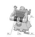
一种汽车后桥总成尺寸自动检测装置,其特征在于:包括检测控制箱1、气缸控制的三轴移动机构2、后桥支架3、支承平台4、后桥夹紧机构5;所述检测控制箱通过旋转支架安装在支承平台的某一个角上;在所述支承平台上面中部设置所述后桥支架;在所述支承平台上面及所述后桥支架外侧左右对称设置两套气缸控制的三轴移动机构,在所述支承平台上面及所述后桥支架后并列设 置两套后桥夹紧机构;其中:所述检测控制箱用于后桥检测过程的控制、显示和处理;所述气缸控制的三轴移动机构自动接触被测后桥的两个安装端面,完成安装端面角度及后桥总长度测量;所述后桥支架用于被测后桥的支承;支承平台是各部件的安装平台;后桥夹紧机构主要实现被测后桥的夹紧,并测量被测后桥两耳轴的间距。 An automatic detection device for the size of an automobile rear axle assembly, characterized in that it includes a detection control box 1, a three-axis moving mechanism 2 controlled by a cylinder, arear axle support 3, asupport platform 4, and a rearaxle clamping mechanism 5; the detection The control box is installed on a certain corner of the support platform through a rotating bracket; the rear axle support is arranged in the middle of the support platform; two sets of cylinders are arranged symmetrically on the support platform and outside the rear axle support. Three-axis moving mechanism, two sets of rear axle clamping mechanisms are arranged side by side on the support platform and behind the rear axle support; wherein: the detection control box is used for the control, display and processing of the rear axle detection process; The three-axis moving mechanism controlled by the cylinder automatically contacts the two installation end surfaces of the rear axle under test, and completes the measurement of the angle of the installation end surfaces and the total length of the rear axle; the rear axle bracket is used for the support of the rear axle under test; the support platform is the The installation platform; the rear axle clamping mechanism mainly realizes the clamping of the rear axle under test and measures the distance between the two trunnions of the rear axle under test. the

所述气缸控制的三轴移动机构2,包括沿Z轴移动导轨208与Z轴移动机构206、沿Y轴移动导轨212与Y轴移动机构215、沿X轴导轨210与X轴移动机构214、用于测量X轴位移的传感器204、测量Y轴位移的传感器203、测量后桥安装端面角度和总长的测量传感器组201、用于确定X轴零点的X轴锁定机构213,用于确定Y轴零点的Y轴锁定机构211、用于确定Z轴总行程的Z轴移动限位块205、后桥定位销202、Z轴移动执行气缸207;其中: The three-axis moving mechanism 2 controlled by the air cylinder includes a Z-axis movingguide rail 208 and a Z-axis moving mechanism 206, a Y-axis movingguide rail 212 and a Y-axis moving mechanism 215, an X-axismoving guide rail 210 and anX-axis moving mechanism 214, Asensor 204 for measuring X-axis displacement, asensor 203 for measuring Y-axis displacement, ameasurement sensor group 201 for measuring the angle and overall length of the rear axle installation end face, anX-axis locking mechanism 213 for determining the zero point of the X-axis, and for determining the Y-axis The Y-axis locking mechanism 211 at the zero point, the Z-axismovement limit block 205 for determining the total stroke of the Z-axis, the rearaxle positioning pin 202, and the Z-axismovement execution cylinder 207; wherein:

所述Z轴移动限位块205、沿Z轴移动导轨208以及Z轴移动执行气缸207的一端经螺钉固定在支承平台4上;所述Z轴移动机构206经导轨滑槽套装在沿Z轴移动导轨208的上方;所述Z轴移动执行气缸207的另一端经耳轴固定在Z轴移动机构206上; One end of the Z-axismovement limit block 205, the Z-axismovement guide rail 208 and the Z-axismovement execution cylinder 207 is fixed on thesupport platform 4 via screws; The top of themoving guide rail 208; the other end of the Z-axis movingexecution cylinder 207 is fixed on the Z-axis moving mechanism 206 through the trunnion;

所述Y轴锁定机构211、X轴锁定机构213通过安装板分别沿X方向、Y方向固定在Z轴移动机构206上;所述沿X轴导轨210、传感器接线盒209通过螺钉固定在Z轴移动机构206的对应位置处;所述X轴移动机构214经导轨滑槽,套装在沿X轴导轨210上; The Y-axis locking mechanism 211 and theX-axis locking mechanism 213 are respectively fixed on the Z-axis moving mechanism 206 along the X direction and the Y direction through the mounting plate; theguide rail 210 along the X-axis and thesensor junction box 209 are fixed on the Z-axis through screws. At the corresponding position of themoving mechanism 206; theX-axis moving mechanism 214 is set on theguide rail 210 along the X-axis through the guide rail chute;

所述测量X轴位移的传感器204由安装夹具及螺钉固定在X轴移动机构214下方,在X轴移动机构214上,加工了Y轴移动导轨212;所述Y轴移动机构215经导轨滑槽套装在Y轴移动导轨212上; Thesensor 204 for measuring the X-axis displacement is fixed below theX-axis moving mechanism 214 by a mounting fixture and screws. On theX-axis moving mechanism 214, a Y-axis movingguide rail 212 is processed; the Y-axis moving mechanism 215 passes through the guide rail chute Set on the Y-axis movingguide rail 212;

三轴移动机构2的工作端面216固定在Y轴移动机构215上,为各传感器提供定位基准;所述后桥定位销202、测量后桥安装端面角度和总长的测量传感器组201采用螺钉固定在与其垂直的工作端面216上;所述测量Y轴位移的传感器203,沿Y轴方向并由夹具和螺钉固定在Y轴移动机构215上。 The workingend face 216 of the three-axis moving mechanism 2 is fixed on the Y-axis moving mechanism 215 to provide a positioning reference for each sensor; themeasuring sensor group 201 of the rearaxle positioning pin 202, measuring the installation end face angle and the total length of the rear axle adopts screws to be fixed on the Y-axis moving mechanism 215. On the workingend face 216 perpendicular thereto; thesensor 203 for measuring the Y-axis displacement is fixed on the Y-axis moving mechanism 215 along the Y-axis direction by clamps and screws. the

所述后桥支架3包括两个Y型支承架302和两个L型支承架301,所述两个Y型支承架302设置在中间,两个L型支承架301设置在两边;所述后桥支架3主要完成被测后桥6的支承。 Therear axle bracket 3 includes two Y-shaped support frames 302 and two L-shaped support frames 301, the two Y-shaped support frames 302 are arranged in the middle, and the two L-shaped support frames 301 are arranged on both sides; Thebridge support 3 mainly completes the support of therear axle 6 under test. the

所述后桥夹紧机构5包括后桥耳轴夹紧爪501、夹紧位移传感器502、夹紧气缸503、夹紧随动导轨504、夹紧位移锁紧机构505、后桥夹紧机构基体506、位移测量标志块507;其中:所述夹紧位移锁紧机构505经螺钉固定在支承平台4上;所述夹紧随动导轨504沿夹紧位移方向,并由螺钉固定在支承平台4上;所述后桥夹紧机构基体506经导轨滑槽,套装在夹紧随动导轨504上;所述夹紧气缸503经支架固定在后桥夹紧机构基体506侧上方,在夹紧气缸503的两侧,分别安装了两个后桥耳轴夹紧爪501;该夹紧爪由螺钉固定在夹紧气缸503的活塞杆上;所述夹紧位移传感器502沿夹紧位移方向固定在后桥夹紧机构基体506上;所述位移测量标志块507装在夹紧位移传感器502的伸出端。 The rearaxle clamping mechanism 5 includes a rear axletrunnion clamping claw 501, aclamping displacement sensor 502, aclamping cylinder 503, a clamping follower guide rail 504, a clamping displacement locking mechanism 505, and a base body of the rear axle clamping mechanism. 506. Displacement measurement marker block 507; wherein: the clamping displacement locking mechanism 505 is fixed on the supportingplatform 4 via screws; the clamping follow-up guide rail 504 is fixed on the supportingplatform 4 by screws along the clamping displacement direction Above; thebase body 506 of the rear axle clamping mechanism is set on the clamping follow-up guide rail 504 through the guide rail chute; theclamping cylinder 503 is fixed on the upper side of thebase body 506 of the rear axle clamping mechanism through the bracket, and the clamping cylinder On both sides of 503, two rear axletrunnion clamping claws 501 are respectively installed; the clamping claws are fixed on the piston rod of theclamping cylinder 503 by screws; theclamping displacement sensor 502 is fixed on the On thesubstrate 506 of the clamping mechanism of the rear axle; the

采用上述汽车后桥总成尺寸自动检测装置的自动检测方法,其特征在于:由所述气缸控制的三轴移动机构自动接触被测后桥的两个安装端面,完成安装端面角度及后桥总长度测量;由所述后桥夹紧机构完成被测后桥的夹紧,并测量被测后桥两耳轴的间距;由所述检测控制箱中的工控机及控制软件进行后桥检测过程的控制、显示和数据处理。具体步骤包括: The automatic detection method using the above-mentioned automatic detection device for the size of the rear axle assembly of the automobile is characterized in that: the three-axis moving mechanism controlled by the cylinder automatically contacts the two installation end faces of the rear axle under test, and completes the installation end face angle and the rear axle assembly. Length measurement; complete the clamping of the rear axle under test by the clamping mechanism of the rear axle, and measure the distance between the two trunnions of the rear axle under test; perform the rear axle detection process by the industrial computer and control software in the detection control box control, display and data processing. Specific steps include:

A1、标定:将Z轴移动机构206、Y轴移动机构215、X轴移动机构214、后桥夹紧机构5锁定,用三坐标仪确定锁定时各机构间的物理位置和尺寸;调整各传感器到线性工作区,并对传感器进行零位标定; A1. Calibration: Lock the Z-axis moving mechanism 206, Y-axis moving mechanism 215,X-axis moving mechanism 214, and rearaxle clamping mechanism 5, and use a three-coordinate instrument to determine the physical position and size of each mechanism when locked; adjust each sensor Go to the linear working area and perform zero calibration on the sensor;

A2、夹紧:松开各锁定机构,将被测后桥6放到后桥支架3上,点击检测控制箱1上的启动按钮,Z轴移动机构206在Z轴移动执行气缸207驱动下,运动止于Z轴移动限位块205,在Z轴运动时,经后桥定位销202导向,Y轴移动机构215、X轴移动机构214进行随动;后桥夹紧机构5在夹紧气缸503驱动下,将被测后桥定位夹紧; A2. Clamping: loosen each locking mechanism, put the measuredrear axle 6 on therear axle support 3, click the start button on the detection control box 1, and the Z-axis moving mechanism 206 is driven by the Z-axis movingexecution cylinder 207, The motion stops at the Z-axismovement limit block 205, and when the Z-axis moves, it is guided by the rearaxle positioning pin 202, followed by the Y-axis moving mechanism 215 and theX-axis moving mechanism 214; the rearaxle clamping mechanism 5 is clamping the cylinder Driven by 503, position and clamp the tested rear axle;

A3、测量:检测控制箱1记录测量X轴位移的传感器204、测量Y轴位移的传感器203、测量后桥安装端面角度和总长的测量传感器组201、夹紧横向位移传感器502的值,同时根据A1步骤得到的物理值,得到被测后桥6的各检测数据; A3, measurement: detection control box 1 records thesensor 204 for measuring the displacement of the X axis, thesensor 203 for measuring the displacement of the Y axis, themeasurement sensor group 201 for measuring the angle of the rear axle installation end face and the total length, the value of the clampinglateral displacement sensor 502, and simultaneously according to The physical value that A1 step obtains, obtains each detection data of measuredrear axle 6;

A4、检测结果:依据检测标准和检测数据,得到被测后桥6合格与否的结论,同时自动生成产品编号,并对检测数据进行数据存储管理。 A4. Test results: According to the test standards and test data, the conclusion of whether the testedrear axle 6 is qualified or not is obtained, and the product number is automatically generated at the same time, and the test data is stored and managed. the

本发明的有益效果是,采用特定的机构对被测后桥进行夹紧和测量,实现了被测后桥的高精度定量测量,提高了产品检测效率。采用了自动检测技术,操作方便,降低了操作人员的劳动强度,保证被测后桥的产品检测和质量稳定。 The beneficial effect of the invention is that a specific mechanism is used to clamp and measure the tested rear axle, which realizes high-precision quantitative measurement of the tested rear axle and improves product testing efficiency. The automatic detection technology is adopted, the operation is convenient, the labor intensity of the operator is reduced, and the product detection and quality of the rear axle under test are guaranteed to be stable. the

附图说明Description of drawings

图1为本发明汽车后桥总成尺寸自动检测装置三维图; Fig. 1 is the three-dimensional figure of automatic detection device of automobile rear axle assembly size of the present invention;

图2和图3为本发明中气缸控制的三轴移动机构三维图; Fig. 2 and Fig. 3 are three-dimensional diagrams of the three-axis moving mechanism controlled by the cylinder in the present invention;

图4为本发明中后桥支架三维图; Fig. 4 is a three-dimensional view of rear axle support in the present invention;

图5和图6为本发明中后桥夹紧机构三维图; Fig. 5 and Fig. 6 are three-dimensional diagrams of rear axle clamping mechanism in the present invention;

图7为本发明自动检测过程流程图。 Fig. 7 is a flowchart of the automatic detection process of the present invention. the

具体实施方式Detailed ways

以下结合附图进行详细说明。 A detailed description will be given below in conjunction with the accompanying drawings. the

图1所示,本发明汽车后桥总成尺寸自动检测装置,包括检测控制箱1、气缸控制的三轴移动机构2、后桥支架3、支承平台4、后桥夹紧机构5;所述检测控制箱1通过旋转支架安装在支承平台4的某一个角上;在所述支承平台4上面中部设置所述后桥支架3;在所述支承平台4上面及所述后桥支架3外侧左右对称设置两套气缸控制的三轴移动机构2,在所述支承平台4上面及所述后桥支架3后并列设置两套后桥夹紧机构5。 As shown in Fig. 1, the automobile rear axle assembly size automatic detection device of the present invention includes a detection control box 1, a three-axis moving mechanism 2 controlled by a cylinder, arear axle support 3, asupport platform 4, and a rearaxle clamping mechanism 5; The detection control box 1 is installed on a certain corner of thesupport platform 4 through a rotating bracket; therear axle support 3 is arranged in the middle of thesupport platform 4; Two sets of cylinder-controlled three-axis moving mechanisms 2 are symmetrically arranged, and two sets of rearaxle clamping mechanisms 5 are arranged side by side on thesupport platform 4 and behind therear axle support 3 . the

其中:所述检测控制箱1中具有工控机(工业控制计算机),由计算机控制软件进行后桥检测过程的控制、显示和处理;所述气缸控制的三轴移动机构2 自动接触被测后桥6的两个安装端面,完成安装端面角度及后桥总长度测量;所述后桥支架3用于被测后桥6的支承;支承平台4是各部件的安装平台;后桥夹紧机构5主要实现被测后桥6的夹紧,并测量被测后桥两耳轴的间距。 Wherein: the detection control box 1 has an industrial computer (industrial control computer), and the control, display and processing of the rear axle detection process are carried out by computer control software; the three-axis moving mechanism 2 controlled by the cylinder automatically contacts the measuredrear axle 6, complete the measurement of the installation end face angle and the total length of the rear axle; therear axle bracket 3 is used for the support of the measuredrear axle 6; thesupport platform 4 is the installation platform for each component; the rearaxle clamping mechanism 5 It mainly realizes the clamping of the testedrear axle 6 and measures the distance between the two trunnions of the tested rear axle. the

图2和图3所示,气缸控制的三轴移动机构2,包括沿Z轴移动导轨208与Z轴移动机构206、沿Y轴移动导轨212与Y轴移动机构215、沿X轴导轨210与X轴移动机构214、用于测量X轴位移的传感器204、测量Y轴位移的传感器203、测量后桥安装端面角度和总长的测量传感器组201、用于确定X轴零点的X轴锁定机构213,用于确定Y轴零点的Y轴锁定机构211、用于确定Z轴总行程的Z轴移动限位块205、后桥定位销202、Z轴移动执行气缸207、以及传感器接线盒209。 As shown in Fig. 2 and Fig. 3, the three-axis moving mechanism 2 controlled by the air cylinder includes a movingguide rail 208 and a Z-axis moving mechanism 206 along the Z axis, amoving guide rail 212 and a Y-axis moving mechanism 215 along the Y axis, and a movingguide rail 210 and a moving mechanism along the X axis.X-axis moving mechanism 214,sensor 204 for measuring X-axis displacement,sensor 203 for measuring Y-axis displacement, measuringsensor group 201 for measuring rear axle installation end face angle and total length,X-axis locking mechanism 213 for determining X-axis zero point , the Y-axis locking mechanism 211 for determining the zero point of the Y-axis, the Z-axismovement limit block 205 for determining the total stroke of the Z-axis, the rearaxle positioning pin 202, the Z-axismovement execution cylinder 207, and thesensor junction box 209. the

其中:所述Z轴移动限位块205、沿Z轴移动导轨208以及Z轴移动执行气缸207的一端经螺钉固定在支承平台4上;所述Z轴移动机构206经导轨滑槽套装在沿Z轴移动导轨208的上方,可实现Z方向移动;所述Z轴移动执行气缸207的另一端经耳轴固定在Z轴移动机构206上,以实现Z轴移动驱动; Wherein: one end of the Z-axismovement limit block 205, the Z-axismovement guide rail 208 and the Z-axismovement execution cylinder 207 is fixed on the supportingplatform 4 via screws; The top of the Z-axis movingguide rail 208 can realize Z-direction movement; the other end of the Z-axis movingexecutive cylinder 207 is fixed on the Z-axis moving mechanism 206 via a trunnion, so as to realize the Z-axis moving drive;

所述Y轴锁定机构211、X轴锁定机构213通过安装板分别沿X方向、Y方向固定在Z轴移动机构206上,并利用定位销原理,实现Y轴、X轴位移锁定;所述沿X轴导轨210、传感器接线盒209通过螺钉固定在Z轴移动机构206的对应位置处;所述X轴移动机构214经导轨滑槽,套装在沿X轴导轨210上,实现X轴移动机构214沿X轴的移动; The Y-axis locking mechanism 211 and theX-axis locking mechanism 213 are respectively fixed on the Z-axis moving mechanism 206 along the X direction and the Y direction through the mounting plate, and use the principle of positioning pins to realize the displacement locking of the Y axis and the X axis; TheX-axis guide rail 210 and thesensor junction box 209 are fixed on the corresponding positions of the Z-axis moving mechanism 206 by screws; theX-axis moving mechanism 214 is set on theguide rail 210 along the X-axis through the guide rail chute to realize theX-axis moving mechanism 214 Movement along the X axis;

所述测量X轴位移的传感器204由安装夹具及螺钉固定在X轴移动机构214下方,随X轴移动机构214一起移动,用来测量X轴移动机构214沿X轴的位移;在X轴移动机构214上,加工了Y轴移动导轨212,实现Y轴移动导向;所述Y轴移动机构215经导轨滑槽套装在Y轴移动导轨212上,用以实现Y轴移动; Thesensor 204 for measuring the X-axis displacement is fixed below theX-axis moving mechanism 214 by a mounting fixture and screws, and moves together with theX-axis moving mechanism 214 to measure the displacement of theX-axis moving mechanism 214 along the X-axis; On themechanism 214, the Y-axis movingguide rail 212 is processed to realize the Y-axis moving guide; the Y-axis moving mechanism 215 is set on the Y-axis movingguide rail 212 through the guide rail chute to realize the Y-axis moving;

三轴移动机构2的工作端面216固定在Y轴移动机构215上,为各传感器提供定位基准;所述后桥定位销202、测量后桥安装端面角度和总长的测量传感 器组201采用螺钉固定在与其垂直的工作端面216上;所述测量Y轴位移的传感器203,沿Y轴方向并由夹具和螺钉固定在Y轴移动机构215上,随Y轴移动机构一起动作,实现Y轴移动机构Y方向位移的测量; The workingend face 216 of three-axis moving mechanism 2 is fixed on the Y-axis moving mechanism 215 to provide positioning references for each sensor; Fixed on the workingend surface 216 perpendicular to it; thesensor 203 for measuring the Y-axis displacement is fixed on the Y-axis moving mechanism 215 along the Y-axis direction by clamps and screws, and moves together with the Y-axis moving mechanism to realize Y-axis movement Measurement of the displacement of the mechanism in the Y direction;

所述传感器接线盒209完成各传感器接线汇总,并最终连接到检测控制箱1上。 Thesensor junction box 209 completes the wiring summary of each sensor, and is finally connected to the detection control box 1 . the

实际运行时,Z轴移动执行气缸207控制的三轴移动机构2以Z轴移动机构206为主动机构,并在Z轴移动执行气缸207驱动下,Z轴移动机构206沿Z轴运行,当后桥定位销202插入被测后桥6的定位孔后,X轴移动机构214、Y轴移动机构215在后桥定位销202的作用下进行随动;所有传感器在达到测量状态时,在检测控制箱1控制下,对该汽车后桥总成产品进行自动测量。其中:各轴锁定机构用于标定整个检测装置零点和各机构相对物理尺寸,对于Z轴总行程的Z轴移动限位块205其作用有两个,一是限制Z轴继续移动,另一作用是作为自动进行数据检测的开始信号。 During actual operation, the three-axis moving mechanism 2 controlled by the Z-axismovement execution cylinder 207 uses the Z-axis movement mechanism 206 as the active mechanism, and driven by the Z-axismovement execution cylinder 207, the Z-axis movement mechanism 206 runs along the Z axis. After thebridge positioning pin 202 is inserted into the positioning hole of the measuredrear axle 6, theX-axis moving mechanism 214 and the Y-axis moving mechanism 215 follow up under the effect of the rearaxle positioning pin 202; Under the control of box 1, the automatic measurement of the rear axle assembly product of the automobile is carried out. Among them: the locking mechanism of each axis is used to calibrate the zero point of the entire detection device and the relative physical size of each mechanism. There are two functions for the Z-axismovement limit block 205 of the total stroke of the Z-axis. One is to limit the Z-axis to continue to move, and the other is to It is used as a start signal for automatic data detection. the

图4所示,后桥支架3,包括两个Y型支承架302和两个L型支承架301,所述两个Y型支承架302设置在中间,两个L型支承架301设置在两边。所述后桥支架3主要完成被测后桥6的支承。 As shown in Figure 4, therear axle bracket 3 includes two Y-shaped support frames 302 and two L-shaped support frames 301, the two Y-shaped support frames 302 are arranged in the middle, and the two L-shaped support frames 301 are arranged on both sides . Therear axle support 3 mainly completes the support of the measuredrear axle 6 . the

图5和图6所示,后桥夹紧机构5,包括后桥耳轴夹紧爪501、夹紧位移传感器502、夹紧气缸503、夹紧随动导轨504、夹紧位移锁紧机构505、后桥夹紧机构基体506、位移测量标志块507。其中:所述夹紧位移锁紧机构505经螺钉固定在支承平台4上;所述夹紧随动导轨504沿夹紧位移方向,并由螺钉固定在支承平台4上;所述后桥夹紧机构基体506经导轨滑槽,套装在夹紧随动导轨504上;所述夹紧气缸503经支架固定在后桥夹紧机构基体506侧上方,在夹紧气缸503的两侧,分别安装了两个后桥耳轴夹紧爪501;该夹紧爪由螺钉固定在夹紧气缸503的活塞杆上,夹紧气缸503的伸长与缩短,直接带动两个后桥耳轴夹紧爪501的松开与夹紧。所述位移测量标志块(507)装在夹紧位移 传感器(502)的伸出端。 As shown in Figures 5 and 6, the rearaxle clamping mechanism 5 includes a rear axletrunnion clamping claw 501, a clampingdisplacement sensor 502, aclamping cylinder 503, a clamping follower guide rail 504, and a clamping displacement locking mechanism 505 , rear axleclamping mechanism substrate 506, displacement measurement mark block 507. Wherein: the clamping displacement locking mechanism 505 is fixed on the supportingplatform 4 via screws; the clamping follow-up guide rail 504 is fixed on the supportingplatform 4 by screws along the clamping displacement direction; the rear axle is clamped Themechanism base 506 is set on the clamping follow-up guide rail 504 through the guide rail chute; theclamping cylinder 503 is fixed on the upper side of the rear axleclamping mechanism base 506 through the bracket, and the two sides of theclamping cylinder 503 are respectively installed Two rear axletrunnion clamping claws 501; the clamping claws are fixed on the piston rod of theclamping cylinder 503 by screws, and the elongation and shortening of theclamping cylinder 503 directly drives the two rear axletrunnion clamping claws 501 loosening and clamping. Described displacement measurement mark piece (507) is contained in the extension end of clamping displacement sensor (502). the

所述两个后桥夹紧机构5中的夹紧气缸503夹紧被测后桥6两个耳轴后,两个后桥夹紧机构5沿夹紧随动导轨504进行随动,以适应被测后桥6两个耳轴的不同间距;所述夹紧位移传感器502沿夹紧位移方向固定在后桥夹紧机构基体506上,该传感器通过测量距位移测量标志块507的距离,来实现被测后桥6两耳轴间距的间接测量。 After the clampingcylinders 503 in the two rearaxle clamping mechanisms 5 clamp the two trunnions of the measuredrear axle 6, the two rearaxle clamping mechanisms 5 follow along the clamping follow-up guide rail 504 to adapt to the The different distances between the two trunnions of the measuredrear axle 6; the clampingdisplacement sensor 502 is fixed on the rear axleclamping mechanism substrate 506 along the clamping displacement direction, and the sensor measures the distance from the displacement measurement marker block 507 to The indirect measurement of the distance between the two trunnions of therear axle 6 under test is realized. the

所述Z轴移动执行气缸207和夹紧气缸503在检测控制箱1同一启动按钮控制下,控制后桥耳轴夹紧爪501和Z轴移动机构206同时运行,当Z轴移动机构206移动到Z轴移动限位块205时,后桥耳轴夹紧爪501也完成后桥的夹紧工作,Y轴移动机构、X轴移动机构在两驱动器件驱动下,进行随动,从而完成整个被测后桥6的尺寸跟随,此时整个被测后桥6达到测量状态,检测控制箱1在获得相应夹紧信号后,自动进行尺寸测量。 The Z-axis movingexecution cylinder 207 and theclamping cylinder 503 are controlled by the same start button of the detection control box 1 to control the rear axletrunnion clamping claw 501 and the Z-axis moving mechanism 206 to run simultaneously. When the Z-axis moving mechanism 206 moves to When the Z-axis moves thelimit block 205, the rear axletrunnion clamping claw 501 also completes the clamping work of the rear axle, and the Y-axis moving mechanism and the X-axis moving mechanism are driven by two driving devices to follow up, thereby completing the whole being driven. The size of the measuredrear axle 6 follows. At this time, the entire measuredrear axle 6 reaches the measurement state, and the detection control box 1 automatically performs dimension measurement after obtaining the corresponding clamping signal. the

汽车后桥总成尺寸自动检测方法: Automobile rear axle assembly size automatic detection method:

采用以上所述本发明汽车后桥总成尺寸自动检测装置,由所述气缸控制的三轴移动机构自动接触被测后桥的两个安装端面,完成安装端面角度及后桥总长度测量;由所述后桥夹紧机构完成被测后桥的夹紧,并测量被测后桥两耳轴的间距;由所述检测控制箱中的工控机及控制软件进行后桥检测过程的控制、显示和数据处理。具体步骤包括: Adopt the auto rear axle assembly size automatic detection device of the present invention described above, the three-axis moving mechanism controlled by the cylinder automatically contacts the two mounting end faces of the measured rear axle, and completes the measurement of the mounting end face angle and the total length of the rear axle; The rear axle clamping mechanism completes the clamping of the rear axle under test, and measures the distance between the two trunnions of the rear axle under test; the control and display of the rear axle detection process is carried out by the industrial computer and control software in the detection control box and data processing. Specific steps include:

A1、标定:将Z轴移动机构206、Y轴移动机构215、X轴移动机构214、后桥夹紧机构5锁定,用三坐标仪确定锁定时各机构间的物理位置和尺寸。调整各传感器到线性工作区,并对传感器进行零位标定。A1. Calibration: Lock the Z-axis moving mechanism 206, the Y-axis moving mechanism 215, theX-axis moving mechanism 214, and the rearaxle clamping mechanism 5, and use a three-coordinate instrument to determine the physical position and size of each mechanism when locked. Adjust each sensor to the linear working area, and perform zero calibration on the sensor.

A2、夹紧:松开各锁定机构,将被测后桥6放到后桥支架3上,点击检测控制箱1上的启动按钮,Z轴移动机构206在Z轴移动执行气缸207驱动下,运动止于Z轴移动限位块205,在Z轴运动时,经后桥定位销202导向,Y轴移动机构215、X轴移动机构214进行随动。后桥夹紧机构5在夹紧气缸503驱动下,将被测后桥定位夹紧。 A2. Clamping: loosen each locking mechanism, put the measuredrear axle 6 on therear axle support 3, click the start button on the detection control box 1, and the Z-axis moving mechanism 206 is driven by the Z-axis movingexecution cylinder 207, The movement stops at the Z-axismovement limit block 205, and when the Z-axis moves, it is guided by the rearaxle positioning pin 202, and the Y-axis moving mechanism 215 and theX-axis moving mechanism 214 follow up. Driven by theclamping cylinder 503, the rearaxle clamping mechanism 5 positions and clamps the rear axle under test. the

A3、测量:检测控制箱1记录测量X轴位移的传感器204、测量Y轴位移的传感器203、测量后桥安装端面角度和总长的测量传感器组201、夹紧横向位移传感器502的值,同时根据A1步骤得到的物理值,得到被测后桥6的各检测数据。 A3, measurement: detection control box 1 records thesensor 204 for measuring the displacement of the X axis, thesensor 203 for measuring the displacement of the Y axis, themeasurement sensor group 201 for measuring the angle of the rear axle installation end face and the total length, the value of the clampinglateral displacement sensor 502, and simultaneously according to The physical value obtained in the step A1 is used to obtain each detection data of therear axle 6 under test. the

A4、检测结果:依据检测标准和检测数据,得到被测后桥6合格与否的结论,同时自动生成产品编号,并对检测数据进行数据存储管理。 A4. Test results: According to the test standards and test data, the conclusion of whether the testedrear axle 6 is qualified or not is obtained, and the product number is automatically generated at the same time, and the test data is stored and managed. the

整个设备在安装完成后,必须进行系统物理尺寸检测及传感器标定。系统标定的目的主要是将传感器标定在线性测量区,并通过系统物理尺寸弥补传感器测量范围不足问题。系统标定时,需在设备标定状态进行。 After the installation of the whole equipment is completed, the physical size of the system must be detected and the sensor calibration must be carried out. The purpose of system calibration is mainly to calibrate the sensor in the linear measurement area, and to make up for the insufficient measurement range of the sensor through the physical size of the system. When the system is calibrated, it needs to be carried out in the equipment calibration state. the

图7所示,本发明自动检测过程流程图。本发明汽车后桥总成尺寸自动检测装置具体操作为: As shown in Fig. 7, the automatic detection process flow chart of the present invention. The concrete operation of the auto rear axle assembly size automatic detection device of the present invention is:

1、操作前系统标定: 1. System calibration before operation:

(a).设备各组件安装与固定。 (a). The installation and fixing of each component of the equipment. the

(b).在未放被测后桥6前,点击检测控制箱1上的启动按钮,Z轴移动执行气缸207和夹紧气缸503开始动作,分别驱动Z轴移动机构206沿Z轴移动导轨208移动到Z轴移动限位块205,后桥耳轴夹紧爪501处于夹紧状态。 (b). Before placing therear axle 6 under test, click the start button on the detection control box 1, the Z-axismovement execution cylinder 207 and theclamping cylinder 503 start to move, respectively drive the Z-axis movement mechanism 206 to move the guide rail along the Z-axis 208 moves to the Z-axismovement limit block 205, and the rear axletrunnion clamping claw 501 is in a clamping state. the

(c).将X轴锁定机构213、Y轴锁定机构211、夹紧位移锁定机构505设定在锁定状态。使用三坐标仪,测量两个三轴移动机构2上工作端面216间的相对距离以及两端面上后桥定位销202的相对空间坐标,同时测量两个后桥耳轴夹紧爪501在锁定位置处的相对坐标。本步骤所测得的值,作为检测装置的零点值,被测后桥6测量时,依据以上所测值,进行尺寸计算。 (c). Set theX-axis locking mechanism 213, the Y-axis locking mechanism 211, and the clamping displacement locking mechanism 505 in a locked state. Use a three-coordinate instrument to measure the relative distance between the working end faces 216 of the two three-axis moving mechanisms 2 and the relative spatial coordinates of the rearaxle positioning pin 202 on both ends, and simultaneously measure the locking position of the two rear axletrunnion clamping claws 501 The relative coordinates at . The value measured in this step is used as the zero point value of the detection device. When the measuredrear axle 6 is measured, the size is calculated based on the above measured value. the

(d).将用于测量X轴位移的传感器204、测量Y轴位移的传感器203以及用于测量夹紧机构位移的夹紧位移传感器502设定在线性工作区,并将锁定位置时的传感器读数清零。 (d). Set thesensor 204 for measuring the displacement of the X axis, thesensor 203 for measuring the displacement of the Y axis, and the clampingdisplacement sensor 502 for measuring the displacement of the clamping mechanism in the linear working area, and set the sensor in the locked position The reading is cleared. the

(e).将位于两个工作端面216上,用于测量后桥安装端面角度和总长的测量传感器组201通过专用量具,调整其顶点到同一个工作平面,并使该平面平 行于工作端面216,随后测量该工作平面距两工作端面216的距离。 (e). On the two working end faces 216, themeasurement sensor group 201 used to measure the angle and total length of the rear axle installation end face is adjusted to the same working plane by a special measuring tool, and the plane is parallel to the workingend face 216, and then measure the distance between the working plane and the two working end faces 216. the

(f).将(c)、(d)、(e)步骤得到的装置锁定尺寸、各工件相对尺寸,存入检测控制箱1的软件中,为测试计算作准备。至此完成系统标定工作。 (f). Store the device locking dimensions obtained in steps (c), (d), and (e) and the relative dimensions of each workpiece into the software of the detection control box 1 to prepare for test calculations. At this point, the system calibration work is completed. the

2、被测后桥夹紧: 2. Clamping of rear axle under test:

(a).系统标定完成后,X轴锁定机构213、Y轴锁定机构211、夹紧位移锁紧机构505设定在松开状态。同时点击检测控制箱1上的停止按钮,在相应气缸驱动下,后桥耳轴夹紧爪501和Z轴移动机构206返回到原位置。整个系统处于准备测试状态。 (a). After the system calibration is completed, theX-axis locking mechanism 213, the Y-axis locking mechanism 211, and the clamping displacement locking mechanism 505 are set in a loose state. Click the stop button on the detection control box 1 at the same time, and under the drive of the corresponding cylinder, the rear axletrunnion clamping claw 501 and the Z-axis moving mechanism 206 return to the original position. The whole system is ready for testing. the

(b).系统测试前,需将被测后桥6放置在后桥支架3上,点击检测控制箱1上的开始按钮,同时手动调整被测后桥6的位置,使后桥定位销202可以轻松插入被测后桥6上的定位孔,并且后桥耳轴夹紧爪501能顺利夹紧被测后桥6的耳轴。 (b). Before the system test, the testedrear axle 6 needs to be placed on therear axle support 3, click the start button on the detection control box 1, and manually adjust the position of the testedrear axle 6 at the same time, so that the rearaxle positioning pin 202 It can be easily inserted into the positioning hole on the testedrear axle 6 , and the rear axletrunnion clamping claw 501 can smoothly clamp the trunnion of the testedrear axle 6 . the

(c).Z轴移动机构206沿Z轴移动导轨208移动到Z轴移动限位块205,并且后桥耳轴夹紧爪501完全夹紧耳轴后,检测控制箱1会收到相应夹紧信号,至此完成被测后桥6的夹紧操作。 (c). The Z-axis moving mechanism 206 moves to the Z-axis movinglimit block 205 along the Z-axis movingguide rail 208, and after the rear axletrunnion clamping claw 501 completely clamps the trunnion, the detection control box 1 will receive the corresponding clamp. Tightening signal, so far the clamping operation of the testedrear axle 6 is completed. the

3、被测后桥测量: 3. Measurement of the rear axle under test:

(a).检测控制箱1在收到被测后桥6已夹紧信号后,自动对各位移传感器进行数据采集。并依据三坐标仪在锁定状态测量的装置锁定尺寸和各工件相对尺寸,按照相应的几何关系,自动计算被测后桥6的各被测尺寸,同时将尺寸显示到检测控制箱1的显示屏上。 (a). The detection control box 1 automatically collects data from each displacement sensor after receiving the clamped signal of therear axle 6 under test. And according to the device locking size measured by the three-coordinate instrument in the locked state and the relative size of each workpiece, according to the corresponding geometric relationship, the measured dimensions of therear axle 6 to be measured are automatically calculated, and the dimensions are displayed on the display screen of the detection control box 1 at the same time superior. the

4、检测结果: 4. Test results:

(a).数据测试完成后,检测控制箱1依据工件测量标准,自动判定被测后桥6合格与否,同时在界面进行实时显示和数据存储。 (a). After the data test is completed, the detection control box 1 automatically determines whether the testedrear axle 6 is qualified or not according to the workpiece measurement standard, and at the same time performs real-time display and data storage on the interface. the

(b).依据检测结果,自动生成打印报表,并在检测控制箱1上内嵌的打印机上,打印测试结论。 (b). According to the test results, a printed report is automatically generated, and the test conclusion is printed on the printer embedded in the test control box 1 . the

(c).测试完成后,点击检测控制箱1上的停止按钮,即可将被测后桥6拆 下,进行下一个工件的测量。至此,整个测试过程完毕。 (c). After the test is completed, click the stop button on the detection control box 1 to remove the testedrear axle 6 to measure the next workpiece. So far, the whole testing process is completed. the

本发明汽车后桥总成尺寸自动检测装置整个测试过程一般只需8秒钟。测试精度为:位移0.01mm,角度0.01度,完全满足了被测后桥6的测试精度和测试速度要求。 The entire test process of the automatic detection device for the size of the automobile rear axle assembly of the present invention generally only needs 8 seconds. The test accuracy is: displacement 0.01 mm, angle 0.01 degrees, fully meeting the test accuracy and test speed requirements of therear axle 6 under test. the

本发明应当理解的是,对本领域技术人员来说,可以根据上述说明加以改进或变换,而所有这些改进和变换都应属于本发明所附权利要求的保护范围。 The present invention should be understood that those skilled in the art can make improvements or transformations according to the above description, and all these improvements and transformations should belong to the protection scope of the appended claims of the present invention. the

Claims (6)

Translated fromChinese
1.一种汽车后桥总成尺寸自动检测装置,其特征在于:包括检测控制箱(1)、气缸控制的三轴移动机构(2)、后桥支架(3)、支承平台(4)、后桥夹紧机构(5);所述检测控制箱通过旋转支架安装在支承平台的某一个角上;在所述支承平台上面中部设置所述后桥支架;在所述支承平台上面及所述后桥支架外侧左右对称设置两套气缸控制的三轴移动机构,在所述支承平台上面及所述后桥支架后并列设置两套后桥夹紧机构;其中:所述检测控制箱用于后桥检测过程的控制、显示和处理;所述气缸控制的三轴移动机构自动接触被测后桥的两个安装端面,完成安装端面角度及后桥总长度测量;所述后桥支架用于被测后桥的支承;支承平台是各部件的安装平台;后桥夹紧机构主要实现被测后桥的夹紧,并测量被测后桥两耳轴的间距。1. An automatic detection device for automobile rear axle assembly size, characterized in that: comprise a three-axis moving mechanism (2) of detection control box (1), cylinder control, rear axle support (3), support platform (4), The rear axle clamping mechanism (5); the detection control box is installed on a certain corner of the support platform through a rotating bracket; the rear axle support is arranged in the middle of the support platform; Two sets of cylinder-controlled three-axis moving mechanisms are symmetrically arranged on the outside of the rear axle support, and two sets of rear axle clamping mechanisms are arranged side by side on the support platform and behind the rear axle support; wherein: the detection control box is used for the rear axle. The control, display and processing of the bridge detection process; the three-axis moving mechanism controlled by the cylinder automatically contacts the two installation end faces of the rear axle under test, and completes the measurement of the installation end face angle and the total length of the rear axle; the rear axle bracket is used to The support of the rear axle is measured; the support platform is the installation platform of each component; the rear axle clamping mechanism mainly realizes the clamping of the rear axle under test and measures the distance between the two trunnions of the rear axle under test.2.根据权利要求1所述的汽车后桥总成尺寸自动检测装置,其特征在于:所述气缸控制的三轴移动机构(2),包括沿Z轴移动导轨(208)与Z轴移动机构(206)、沿Y轴移动导轨(212)与Y轴移动机构(215)、沿X轴导轨(210)与X轴移动机构(214)、用于测量X轴位移的传感器(204)、测量Y轴位移的传感器(203)、测量后桥安装端面角度和总长的测量传感器组(201)、用于确定X轴零点的X轴锁定机构(213),用于确定Y轴零点的Y轴锁定机构(211)、用于确定Z轴总行程的Z轴移动限位块(205)、后桥定位销(202)、Z轴移动执行气缸(207);其中:2. The auto rear axle assembly size automatic detection device according to claim 1, characterized in that: the three-axis moving mechanism (2) controlled by the cylinder includes a Z-axis moving guide rail (208) and a Z-axis moving mechanism (206), along the Y-axis moving guide rail (212) and the Y-axis moving mechanism (215), along the X-axis guide rail (210) and the X-axis moving mechanism (214), for measuring the sensor (204) of the X-axis displacement, measuring A sensor (203) for Y-axis displacement, a measurement sensor group (201) for measuring the angle and overall length of the rear axle installation end face, an X-axis locking mechanism (213) for determining the zero point of the X-axis, and a Y-axis lock for determining the zero point of the Y-axis Mechanism (211), Z-axis movement limit block (205) for determining the Z-axis total stroke, rear axle positioning pin (202), Z-axis movement execution cylinder (207); wherein:所述Z轴移动限位块(205)、沿Z轴移动导轨(208)以及Z轴移动执行气缸(207)的一端经螺钉固定在支承平台(4)上;所述Z轴移动机构(206)经导轨滑槽套装在沿Z轴移动导轨(208)的上方;所述Z轴移动执行气缸(207)的另一端经耳轴固定在Z轴移动机构(206)上;One end of the Z-axis moving stop block (205), the Z-axis moving guide rail (208) and the Z-axis moving execution cylinder (207) is fixed on the supporting platform (4) through screws; the Z-axis moving mechanism (206 ) is set on the top of the Z-axis moving guide rail (208) through the guide rail chute; the other end of the Z-axis moving execution cylinder (207) is fixed on the Z-axis moving mechanism (206) through the trunnion;所述Y轴锁定机构(211)、X轴锁定机构(213)通过安装板分别沿X方向、Y方向固定在Z轴移动机构(206)上;所述沿X轴导轨(210)、传感器接线盒(209)通过螺钉固定在Z轴移动机构(206)的对应位置处;所述X轴移动机 构(214)经导轨滑槽,套装在沿X轴导轨(210)上;The Y-axis locking mechanism (211) and the X-axis locking mechanism (213) are respectively fixed on the Z-axis moving mechanism (206) along the X direction and the Y direction through the mounting plate; the X-axis guide rail (210), sensor wiring The box (209) is fixed at the corresponding position of the Z-axis moving mechanism (206) by screws; the X-axis moving mechanism (214) is set on the guide rail (210) along the X-axis through the guide rail chute;所述测量X轴位移的传感器(204)由安装夹具及螺钉固定在X轴移动机构(214)下方,在X轴移动机构(214)上,加工了Y轴移动导轨(212);所述Y轴移动机构(215)经导轨滑槽套装在Y轴移动导轨(212)上;The sensor (204) for measuring the X-axis displacement is fixed below the X-axis moving mechanism (214) by a mounting fixture and screws, and the Y-axis moving guide rail (212) is processed on the X-axis moving mechanism (214); The axis moving mechanism (215) is set on the Y-axis moving guide rail (212) through the guide rail chute;该三轴移动机构(2)的工作端面(216)固定在Y轴移动机构(215)上,为各传感器提供定位基准;所述后桥定位销(202)、测量后桥安装端面角度和总长的测量传感器组(201)采用螺钉固定在与其垂直的工作端面(216)上;所述测量Y轴位移的传感器(203),沿Y轴方向并由夹具和螺钉固定在Y轴移动机构(215)上。The working end surface (216) of this three-axis moving mechanism (2) is fixed on the Y-axis moving mechanism (215) to provide a positioning reference for each sensor; The measurement sensor group (201) is fixed on the working end surface (216) perpendicular to it with screws; the sensor (203) for measuring the Y-axis displacement is fixed on the Y-axis moving mechanism (215) along the Y-axis direction and by clamps and screws. )superior.3.根据权利要求1所述的汽车后桥总成尺寸自动检测装置,其特征在于:所述后桥支架(3)包括两个Y型支承架(302)和两个L型支承架(301),所述两个Y型支承架(302)设置在中间,两个L型支承架(301)设置在两边。3. The auto rear axle assembly size automatic detection device according to claim 1, characterized in that: the rear axle support (3) comprises two Y-shaped support frames (302) and two L-shaped support frames (301 ), the two Y-shaped support frames (302) are arranged in the middle, and the two L-shaped support frames (301) are arranged on both sides.4.根据权利要求1所述的汽车后桥总成尺寸自动检测装置,其特征在于:所述后桥夹紧机构(5)包括后桥耳轴夹紧爪(501)、夹紧位移传感器(502)、夹紧气缸(503)、夹紧随动导轨(504)、夹紧位移锁紧机构(505)、后桥夹紧机构基体(506)、位移测量标志块(507);其中:所述夹紧位移锁紧机构(505)经螺钉固定在支承平台(4)上;所述夹紧随动导轨(504)沿夹紧位移方向,并由螺钉固定在支承平台(4)上;所述后桥夹紧机构基体(506)经导轨滑槽,套装在夹紧随动导轨(504)上;所述夹紧气缸(503)经支架固定在后桥夹紧机构基体(506)侧上方,在夹紧气缸(503)的两侧,分别安装了两个后桥耳轴夹紧爪(501);该夹紧爪由螺钉固定在夹紧气缸(503)的活塞杆上;所述夹紧位移传感器(502)沿夹紧位移方向固定在后桥夹紧机构基体(506)上;所述位移测量标志块(507)装在夹紧位移传感器(502)的伸出端。4. The auto rear axle assembly size automatic detection device according to claim 1, characterized in that: the rear axle clamping mechanism (5) comprises a rear axle trunnion clamping claw (501), a clamping displacement sensor ( 502), clamping cylinder (503), clamping follow-up guide rail (504), clamping displacement locking mechanism (505), rear axle clamping mechanism substrate (506), displacement measurement mark block (507); wherein: The clamping displacement locking mechanism (505) is fixed on the supporting platform (4) via screws; the clamping follow-up guide rail (504) is fixed on the supporting platform (4) by screws along the clamping displacement direction; The rear axle clamping mechanism base (506) is set on the clamping follow-up guide rail (504) through the guide rail chute; the clamping cylinder (503) is fixed on the upper side of the rear axle clamping mechanism base (506) through the bracket , on both sides of the clamping cylinder (503), two rear axle trunnion clamping claws (501) are respectively installed; the clamping claws are fixed on the piston rod of the clamping cylinder (503) by screws; The tight displacement sensor (502) is fixed on the base body (506) of the clamping mechanism of the rear axle along the clamping displacement direction; the displacement measurement mark block (507) is installed on the protruding end of the clamping displacement sensor (502).5.根据权利要求1所述的汽车后桥总成尺寸自动检测装置的自动检测方法,其特征在于:由所述气缸控制的三轴移动机构自动接触被测后桥的两个安 装端面,完成安装端面角度及后桥总长度测量;由所述后桥夹紧机构完成被测后桥的夹紧,并测量被测后桥两耳轴的间距;由所述检测控制箱中的工控机及控制软件进行后桥检测过程的控制、显示和数据处理。5. The automatic detection method of the automobile rear axle assembly size automatic detection device according to claim 1, characterized in that: the three-axis moving mechanism controlled by the cylinder automatically contacts the two installation end faces of the rear axle under test, Complete the measurement of the installation end face angle and the total length of the rear axle; complete the clamping of the rear axle under test by the clamping mechanism of the rear axle, and measure the distance between the two trunnions of the rear axle under test; the industrial computer in the detection control box and control software for the control, display and data processing of the rear axle detection process.6.根据权利要求1、2及5所述的汽车后桥总成尺寸自动检测装置的自动检测方法,其特征在于:具体步骤包括:6. according to the automatic detection method of the described automobile rear axle assembly size automatic detection device of claim 1, 2 and 5, it is characterized in that: concrete steps comprise:A1、标定:将Z轴移动机构(206)、Y轴移动机构(215)、X轴移动机构(214)、后桥夹紧机构(5)锁定,用三坐标仪确定锁定时各机构间的物理位置和尺寸;调整各传感器到线性工作区,并对传感器进行零位标定;A1. Calibration: Lock the Z-axis moving mechanism (206), the Y-axis moving mechanism (215), the X-axis moving mechanism (214), and the rear axle clamping mechanism (5), and use a three-coordinate instrument to determine the distance between each mechanism when locking. Physical location and size; adjust each sensor to the linear working area, and perform zero calibration on the sensor;A2、夹紧:松开各锁定机构,将被测后桥(6)放到后桥支架(3)上,点击检测控制箱(1)上的启动按钮,Z轴移动机构(206)在Z轴移动执行气缸(207)驱动下,运动止于Z轴移动限位块(205),在Z轴运动时,经后桥定位销(202)导向,Y轴移动机构(215)、X轴移动机构(214)进行随动;后桥夹紧机构(5)在夹紧气缸(503)驱动下,将被测后桥定位夹紧;A2. Clamping: loosen each locking mechanism, put the measured rear axle (6) on the rear axle support (3), click the start button on the detection control box (1), and the Z-axis moving mechanism (206) will Driven by the axis movement execution cylinder (207), the movement stops at the Z-axis movement limit block (205). When the Z-axis moves, it is guided by the rear axle positioning pin (202), and the Y-axis movement mechanism (215) and the X-axis move The mechanism (214) is followed; the rear axle clamping mechanism (5) is driven by the clamping cylinder (503), and the measured rear axle is positioned and clamped;A3、测量:检测控制箱(1)记录测量X轴位移的传感器(204)、测量Y轴位移的传感器(203)、测量后桥安装端面角度和总长的测量传感器组(201)、夹紧横向位移传感器(502)的值,同时根据A1步骤得到的物理值,得到被测后桥(6)的各检测数据;A3, measurement: detection control box (1) records the sensor (204) for measuring X-axis displacement, the sensor (203) for measuring Y-axis displacement, the measurement sensor group (201) for measuring the angle and total length of the rear axle installation end face, clamping lateral The value of displacement sensor (502), obtains each detection data of measured rear axle (6) according to the physical value that A1 step obtains simultaneously;A4、检测结果:依据检测标准和检测数据,得到被测后桥(6)合格与否的结论,同时自动生成产品编号,并对检测数据进行数据存储管理。 A4. Test results: According to the test standards and test data, the conclusion of whether the tested rear axle (6) is qualified or not is obtained, and the product number is automatically generated at the same time, and the test data is stored and managed. the
CN201210016290.XA2012-01-182012-01-18Automatic detection device and method for size of automobile rear axle assemblyExpired - Fee RelatedCN102607502B (en)

Priority Applications (1)

Application NumberPriority DateFiling DateTitle
CN201210016290.XACN102607502B (en)2012-01-182012-01-18Automatic detection device and method for size of automobile rear axle assembly

Applications Claiming Priority (1)

Application NumberPriority DateFiling DateTitle
CN201210016290.XACN102607502B (en)2012-01-182012-01-18Automatic detection device and method for size of automobile rear axle assembly

Publications (2)

Publication NumberPublication Date
CN102607502Atrue CN102607502A (en)2012-07-25
CN102607502B CN102607502B (en)2014-05-28

Family

ID=46525107

Family Applications (1)

Application NumberTitlePriority DateFiling Date
CN201210016290.XAExpired - Fee RelatedCN102607502B (en)2012-01-182012-01-18Automatic detection device and method for size of automobile rear axle assembly

Country Status (1)

CountryLink
CN (1)CN102607502B (en)

Cited By (15)

* Cited by examiner, † Cited by third party
Publication numberPriority datePublication dateAssigneeTitle
CN102865846A (en)*2012-09-272013-01-09宁波敏实汽车零部件技术研发有限公司Fixture and method for detecting size of automobile door frame
CN102950170A (en)*2012-10-242013-03-06芜湖可挺汽车底盘件有限公司Device for detecting rear axle of car
CN103196413A (en)*2013-03-192013-07-10浙江万向系统有限公司Angle digital display comprehensive gauge
CN103512461A (en)*2013-10-182014-01-15安徽万安汽车零部件有限公司Auxiliary vehicle frame detecting tool
CN103644823A (en)*2013-11-262014-03-19柳州六和方盛机械有限公司Passenger vehicle chassis part rear axle assembly general gauge
CN103808235A (en)*2014-02-142014-05-21奇瑞汽车股份有限公司Gap detection device of constant velocity universal joint drive shaft assembly
CN107063152A (en)*2017-06-262017-08-18宁波中亿自动化装备有限公司Automobile axle detection means and automobile detection system
CN107194051A (en)*2017-05-112017-09-22重庆长安汽车股份有限公司A kind of back axle mission nonlinear strength analysis method
CN107655434A (en)*2016-07-262018-02-02上海北特科技股份有限公司The detection device of parts
CN108759747A (en)*2018-07-242018-11-06台州屹丰汽车模具有限公司Cutting support check system
CN109297445A (en)*2018-11-272019-02-01安徽江淮汽车集团股份有限公司A kind of torsion beam examines positioning device and method
WO2020057101A1 (en)*2018-09-182020-03-26江苏神通阀门股份有限公司Detection system for measuring pipeline size parameters and detection method therefor
CN113390375A (en)*2021-07-082021-09-14刘璐Flatness detection device for furniture
CN113670156A (en)*2021-07-132021-11-19成都考斯特车桥制造有限责任公司Rear-axle housing owner subtracts hole and synthesizes and examine utensil
CN115325970A (en)*2022-06-132022-11-11中国第一汽车股份有限公司Method, system, equipment, storage medium and vehicle for rapidly improving dimensional accuracy of vehicle body by replacing embedding gauge with functional dimension

Citations (5)

* Cited by examiner, † Cited by third party
Publication numberPriority datePublication dateAssigneeTitle
US5760302A (en)*1996-07-081998-06-02Ford Global Technologies, Inc.Driveline system balancing method and apparatus
CN201149477Y (en)*2007-12-242008-11-12力邦测控设备(洛阳)有限公司Instrument for measuring automatically rear axle housing
CN201662387U (en)*2010-03-162010-12-01福建胜亚模具有限公司Detection measuring implement of automobile rear axle belt sensor
CN201749027U (en)*2010-06-222011-02-16山东临工工程机械有限公司Drive axle reliability test bed
CN202083562U (en)*2011-03-212011-12-21中国长安汽车集团股份有限公司四川建安车桥分公司Running test device for rear axle assembly of automobile

Patent Citations (5)

* Cited by examiner, † Cited by third party
Publication numberPriority datePublication dateAssigneeTitle
US5760302A (en)*1996-07-081998-06-02Ford Global Technologies, Inc.Driveline system balancing method and apparatus
CN201149477Y (en)*2007-12-242008-11-12力邦测控设备(洛阳)有限公司Instrument for measuring automatically rear axle housing
CN201662387U (en)*2010-03-162010-12-01福建胜亚模具有限公司Detection measuring implement of automobile rear axle belt sensor
CN201749027U (en)*2010-06-222011-02-16山东临工工程机械有限公司Drive axle reliability test bed
CN202083562U (en)*2011-03-212011-12-21中国长安汽车集团股份有限公司四川建安车桥分公司Running test device for rear axle assembly of automobile

Non-Patent Citations (2)

* Cited by examiner, † Cited by third party
Title
周学锋等: "在线检测量仪在轿车后桥自动线上的应用", 《汽车工艺与材料》, no. 12, 31 December 2009 (2009-12-31)*
宫耀旺: "汽车驱动桥总成综合试验台的研究与开发", 《中国优秀硕士学位论文全文数据库》, 30 June 2009 (2009-06-30)*

Cited By (23)

* Cited by examiner, † Cited by third party
Publication numberPriority datePublication dateAssigneeTitle
CN102865846B (en)*2012-09-272016-06-29宁波敏实汽车零部件技术研发有限公司A kind of detection method of automobile door frame size
CN102865846A (en)*2012-09-272013-01-09宁波敏实汽车零部件技术研发有限公司Fixture and method for detecting size of automobile door frame
CN102950170A (en)*2012-10-242013-03-06芜湖可挺汽车底盘件有限公司Device for detecting rear axle of car
CN103196413A (en)*2013-03-192013-07-10浙江万向系统有限公司Angle digital display comprehensive gauge
CN103196413B (en)*2013-03-192016-08-03浙江万向系统有限公司A kind of angle digital display comprehensive gauge
CN103512461A (en)*2013-10-182014-01-15安徽万安汽车零部件有限公司Auxiliary vehicle frame detecting tool
CN103644823A (en)*2013-11-262014-03-19柳州六和方盛机械有限公司Passenger vehicle chassis part rear axle assembly general gauge
CN103644823B (en)*2013-11-262016-05-11柳州六和方盛机械有限公司Passenger car chassis member hind axle assembly universal check tool
CN103808235A (en)*2014-02-142014-05-21奇瑞汽车股份有限公司Gap detection device of constant velocity universal joint drive shaft assembly
CN107655434A (en)*2016-07-262018-02-02上海北特科技股份有限公司The detection device of parts
CN107655434B (en)*2016-07-262024-03-08上海北特科技股份有限公司Detection equipment for parts
CN107194051A (en)*2017-05-112017-09-22重庆长安汽车股份有限公司A kind of back axle mission nonlinear strength analysis method
CN107194051B (en)*2017-05-112020-10-16重庆长安汽车股份有限公司Nonlinear intensity analysis method for rear axle system
CN107063152B (en)*2017-06-262023-04-25宁波中亿自动化装备有限公司Automobile rear axle detection device and automobile detection system
CN107063152A (en)*2017-06-262017-08-18宁波中亿自动化装备有限公司Automobile axle detection means and automobile detection system
CN108759747A (en)*2018-07-242018-11-06台州屹丰汽车模具有限公司Cutting support check system
CN108759747B (en)*2018-07-242023-10-27台州屹丰汽车模具有限公司Cutting support checking system
WO2020057101A1 (en)*2018-09-182020-03-26江苏神通阀门股份有限公司Detection system for measuring pipeline size parameters and detection method therefor
CN109297445A (en)*2018-11-272019-02-01安徽江淮汽车集团股份有限公司A kind of torsion beam examines positioning device and method
CN113390375A (en)*2021-07-082021-09-14刘璐Flatness detection device for furniture
CN113670156A (en)*2021-07-132021-11-19成都考斯特车桥制造有限责任公司Rear-axle housing owner subtracts hole and synthesizes and examine utensil
CN113670156B (en)*2021-07-132024-03-26成都考斯特车桥制造有限责任公司Rear axle housing main hole-reducing comprehensive gauge
CN115325970A (en)*2022-06-132022-11-11中国第一汽车股份有限公司Method, system, equipment, storage medium and vehicle for rapidly improving dimensional accuracy of vehicle body by replacing embedding gauge with functional dimension

Also Published As

Publication numberPublication date
CN102607502B (en)2014-05-28

Similar Documents

PublicationPublication DateTitle
CN102607502A (en)Automatic detection device and method for size of automobile rear axle assembly
CN101949687B (en) Detection method of automobile door based on vision measurement
CN110978059B (en) A portable six-axis manipulator calibration device and calibration method thereof
JP5823306B2 (en) Calibration method of surface texture measuring machine
KR101902080B1 (en)Detection device of pipe alignment status by using image information and laser sensor and method thereof
CN102230789B (en)Flatness measuring instrument of high-speed railway steel rail and measuring surface positioning method thereof
CN202599371U (en)Measuring device based on integration of vision sensor and three-coordinate measuring machine
CN103047935B (en)Upper surface of base plate detection method and chalker
CN103659467B (en)The scaling method of the axial pretravel of touch trigger probe
CN102288149B (en)Brake disc camber angle detection device and brake disc production line device
CN108801174A (en)A kind of detection device and its detection method for measuring not rounded internal bore profile
CN110108238A (en)It is a kind of for measuring the measuring system and measurement method of part flatness
CN202420361U (en)Automotive longitudinal beam plate measurement checking tool
CN104515487A (en)Two-in-one full-automatic three-Z-axis measuring instrument
CN101377403B (en) A device and method for measuring the position accuracy of a straight line edge of a part
CN106289059A (en)Bogie detection device
CN203240988U (en)Vehicle oil filling pipe assembly checking tool
CN204346405U (en)Hook tongue Curved dectection device and detector
CN207534637U (en)Pneumatic clamping jaw device and system
CN108050974A (en)High-precision detection machine
CN108592851A (en)A kind of workpiece symmetry detecting tool and detection method
CN113624136B (en)Part detection device and part detection device calibration method
CN104215186B (en)Device and method for measuring spatial position coordinate relationship of measuring head system of swing arm type contourgraph
CN204854766U (en)Because of levelling staff error of zero point made of baked clay detection and adjusting device based on image vision
CN204666093U (en)A kind of non-contact measurement mechanical arm

Legal Events

DateCodeTitleDescription
C06Publication
PB01Publication
C10Entry into substantive examination
SE01Entry into force of request for substantive examination
C14Grant of patent or utility model
GR01Patent grant
CF01Termination of patent right due to non-payment of annual fee

Granted publication date:20140528

Termination date:20170118


[8]ページ先頭

©2009-2025 Movatter.jp