CN102606073A - Guide mechanism for directing rotary steering drilling tool - Google Patents
Guide mechanism for directing rotary steering drilling toolDownload PDFInfo
- Publication number
- CN102606073A CN102606073ACN2012100994605ACN201210099460ACN102606073ACN 102606073 ACN102606073 ACN 102606073ACN 2012100994605 ACN2012100994605 ACN 2012100994605ACN 201210099460 ACN201210099460 ACN 201210099460ACN 102606073 ACN102606073 ACN 102606073A
- Authority
- CN
- China
- Prior art keywords
- hydraulic
- offset
- shaft
- motor
- drilling fluid
- Prior art date
- Legal status (The legal status is an assumption and is not a legal conclusion. Google has not performed a legal analysis and makes no representation as to the accuracy of the status listed.)
- Pending
Links
- 238000005553drillingMethods0.000titleclaimsabstractdescription44
- 230000007246mechanismEffects0.000titleclaimsabstractdescription10
- 239000012530fluidSubstances0.000claimsabstractdescription15
- 239000003381stabilizerSubstances0.000claimsabstractdescription7
- 230000033001locomotionEffects0.000claimsdescription12
- 238000007789sealingMethods0.000claimsdescription12
- 229910000831SteelInorganic materials0.000claimsdescription4
- 239000010959steelSubstances0.000claimsdescription4
- 230000008901benefitEffects0.000abstractdescription7
- 238000000034methodMethods0.000abstractdescription5
- 238000006073displacement reactionMethods0.000abstractdescription3
- 230000008569processEffects0.000abstractdescription3
- 238000005516engineering processMethods0.000description5
- 238000010586diagramMethods0.000description2
- 239000007788liquidSubstances0.000description2
- 230000003068static effectEffects0.000description2
- 230000005540biological transmissionEffects0.000description1
- 230000008859changeEffects0.000description1
- 238000004140cleaningMethods0.000description1
- 230000008878couplingEffects0.000description1
- 238000010168coupling processMethods0.000description1
- 238000005859coupling reactionMethods0.000description1
- 230000007547defectEffects0.000description1
- 230000000694effectsEffects0.000description1
- 230000005611electricityEffects0.000description1
- 239000003208petroleumSubstances0.000description1
- 230000001105regulatory effectEffects0.000description1
- 238000005096rolling processMethods0.000description1
Images

Landscapes
- Earth Drilling (AREA)
Abstract
Translated fromChinese
Description
Translated fromChinese技术领域technical field
本发明涉及一种石油勘探导向钻井工具,特别涉及一种指向式旋转导向钻井工具的导向机构。 The invention relates to an oil exploration steering drilling tool, in particular to a guiding mechanism of a pointing rotary steering drilling tool. the
背景技术Background technique
随着石油工业的发展,开发深井,超深井,大位移井,水平井,以及多目标井成为需要。并且要更经常地面对海洋,沙漠等一些复杂构造地层。勘探开发的难度大大增加。这些现状给钻井技术提出了提高效率,提高在恶劣环境和复杂地质条件下的钻井能力,和实现智能化等一系列新要求。 With the development of the petroleum industry, it becomes necessary to develop deep wells, ultra-deep wells, extended-reach wells, horizontal wells, and multi-target wells. And it is necessary to face some complex structural strata such as oceans and deserts more often. The difficulty of exploration and development has greatly increased. These current situations have put forward a series of new requirements for drilling technology, such as improving efficiency, improving drilling capabilities in harsh environments and complex geological conditions, and realizing intelligence. the
旋转导向钻井技术是钻井工程领域的高新技术,代表着世界先进的钻井技术发展方向。目前,在世界范围内水平井、大位移井、分支井等高难度的复杂井正蓬勃发展,常规钻井技术难以适应需要,并且具有本身难以克服的缺点:井眼轨迹控制精度差,钻井极限深度受到限制,井眼清洗不良,较多的起下钻次数引起的钻井速度降低等。所以必须依靠先进的旋转导向钻井技术才能保证井眼轨迹的准确无误。 Rotary steerable drilling technology is a high-tech in the field of drilling engineering, representing the development direction of the world's advanced drilling technology. At present, complex and difficult wells such as horizontal wells, extended-reach wells, and lateral wells are developing vigorously worldwide. Conventional drilling technology is difficult to meet the needs, and has its own insurmountable shortcomings: poor wellbore trajectory control accuracy, drilling limit depth Restricted, poor wellbore cleaning, lower drilling speed caused by more tripping times, etc. Therefore, it is necessary to rely on advanced rotary steerable drilling technology to ensure the accuracy of wellbore trajectory. the
目前旋转导向钻井工具主要分为静态偏置式旋转导向钻井工具和动态偏置式旋转导向钻井工具。按偏置机构的导向方式的不同,又可分为推靠式和指向式。推靠式旋转导向系统侧向力大,造斜率高, 但旋转导向钻出的井眼狗腿大,轨迹波动大,不平滑。钻头和钻头轴承的磨损较严重。 At present, rotary steerable drilling tools are mainly divided into static offset rotary steerable drilling tools and dynamic offset rotary steerable drilling tools. According to the different guiding methods of the biasing mechanism, it can be divided into push-to-type and point-to-point. The push-on rotary steerable system has a large lateral force and a high build-up rate, but the wellbore drilled by the rotary steerable has large doglegs, and the trajectory fluctuates greatly and is not smooth. The drill and drill bearings are more severely worn. the
指向式旋转导向系统能钻出较平滑的井眼;摩阻和扭矩较小;可以使用较大的钻压;机械钻速较高;有助于发挥钻头的性能;钻头及其轴承承受的侧向载荷较小;极限位移增加。 The pointing rotary steerable system can drill a smoother wellbore; the friction and torque are small; a large bit pressure can be used; the ROP is high; it is helpful to the performance of the drill bit; The load is smaller; the limit displacement is increased. the
而动态式旋转导向系统相比静态式具有钻柱受力情况良好,调节更加灵活等优点,已经是旋转导向钻具领域研究的重点. Compared with the static type, the dynamic rotary steerable system has the advantages of better stress on the drill string and more flexible adjustment, and has become the focus of research in the field of rotary steerable drilling tools.
发明内容Contents of the invention
为了克服现有技术的缺陷,本发明的目的在于提供一种指向式旋转导向钻井工具的导向机构,结合了动态式和指向式两者的特点,既有动态式钻柱受力情况良好,调节灵活的优点,又有指向式钻具在特殊地质条件导向能力强,井眼质量好的优点。 In order to overcome the defects of the prior art, the object of the present invention is to provide a steering mechanism of a pointing rotary steerable drilling tool, which combines the characteristics of both the dynamic type and the pointing type. It has the advantage of being flexible, and the directional drilling tool has the advantages of strong steering ability in special geological conditions and good borehole quality. the
为了达到上述目的,本发明的技术方案是这样实现的: In order to achieve the above object, technical scheme of the present invention is achieved in that:
一种指向式旋转导向钻井工具的导向机构,包括近钻头稳定器1,近钻头稳定器1固定在旋转外套2的末端,旋转外套2内固定有万向节5,万向节5中的钢球6放置在偏置轴3的球窝中,偏置轴3与外套2末端之间安装有第一密封圈8,偏置轴3末端用来安装钻头4,偏置轴3的上端伸入在偏置轴承10中,并通过柔性密封圈17与钻井液通道19相联,偏置轴承10的外表面上作用有四个液压活塞9,液压活塞9通过液压介质14推动,液压活塞9在液压腔22中运动,液压腔22开在旋转外套2上,液压腔22中安装有传感器11,液压介质通道15位于旋转外套2内部,液压介质通道15通过液压腔22与 两个伺服阀12相联,伺服阀12与控制单元21相连,液压介质14通过液压泵13提供压力能,液压泵13的输入轴与电机16的输出轴相连,电机16的输入轴与涡轮18的主轴相连,涡轮18末端为钻井液通道19,钻井液通道19与电机16之间安装有第二密封圈20。 A guiding mechanism of a pointing rotary steerable drilling tool, comprising a near-drill stabilizer 1, which is fixed at the end of a rotating outer casing 2, and a universal joint 5 is fixed inside the rotating outer casing 2, and the steel in the universal joint 5 The ball 6 is placed in the ball socket of the offset shaft 3, the first sealing ring 8 is installed between the offset shaft 3 and the end of the outer casing 2, the end of the offset shaft 3 is used to install the drill bit 4, and the upper end of the offset shaft 3 extends into the In the offset bearing 10, which is connected with the
本发明结合了动态式和指向式两者的特点,兼有动态式系统灵活,受力好的优点和指向式钻具更好的井斜方位控制,井眼质量好的优点。 The present invention combines the characteristics of both the dynamic type and the pointing type, and has the advantages of flexible dynamic system and good force bearing and better well deviation and azimuth control of the pointing type drilling tool, and the advantages of good borehole quality. the
附图说明Description of drawings
图1是本发明的结构示意图。 Fig. 1 is a structural schematic diagram of the present invention. the
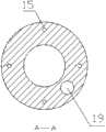
图2是本发明的A-A向结构示意图。 Fig. 2 is a schematic diagram of the structure of the present invention in the direction of A-A. the
具体实施方式Detailed ways
下面结合附图对本发明做详细叙述。 The present invention is described in detail below in conjunction with accompanying drawing. the
参照图1、图2,一种指向式旋转导向钻井工具的导向机构,包括近钻头稳定器1,近钻头稳定器1通过螺纹连接形式固定在旋转外套2的末端,旋转外套2内固定有万向节5,万向节5中的钢球6放置在偏置轴3的球窝中,从而使偏置轴3和旋转外套2一同旋转,偏置轴3与外套2末端之间安装有第一密封圈8,用来阻止泥浆进入万向节5,偏置轴3末端用来安装钻头4,偏置轴3的上端伸入在偏置轴承10中,并通过柔性密封圈17和钻井液通道19相联,偏置轴承10的外表面上作用有四个液压活塞9,液压活塞9通过液压介质14推动,液压活塞9在液压腔22中运动,液压腔22开在旋转外套2上,液压腔22中安装有传感器11,用来检测液压活塞9的位置。液压介 质通道15位于旋转外套2内部,液压介质通道15通向液压腔22与两个伺服阀12相联,伺服阀12受到控制单元21的控制。液压介质14的压力能靠液压泵13提供,液压泵13靠电机16驱动,电机16依靠钻井液冲刷涡轮18旋转产生电能。涡轮18末端为钻井液通道19,钻井液通道19与电机16之间安装有第二密封圈20,用来阻止钻井液侵入电机16以及液压介质14. Referring to Fig. 1 and Fig. 2, a guiding mechanism of a pointing rotary steerable drilling tool includes a near-drill stabilizer 1, which is fixed on the end of the rotating outer casing 2 through a threaded connection, and the rotating outer casing 2 is fixed with ten thousand The joint 5, the steel ball 6 in the universal joint 5 is placed in the ball socket of the offset shaft 3, so that the offset shaft 3 and the rotating outer casing 2 rotate together, and the second end of the offset shaft 3 and the outer casing 2 is installed A sealing ring 8 is used to prevent mud from entering the universal joint 5. The end of the offset shaft 3 is used to install the drill bit 4. The upper end of the offset shaft 3 extends into the offset bearing 10 and passes through the flexible sealing ring 17 and the drilling fluid. The
本发明的工作原理为:旋转导向钻井底部钻具中的近钻头稳定器1与旋转外套2紧密结合并保持旋转,旋转外套2受到钻柱驱动,钻柱由井上钻机带动旋转。偏置轴3通过联接方式安装在旋转外套2内,受到旋转外套的直接驱动来进行钻井工作。偏置轴的底部开有锥形螺纹,钻头4通过锥螺纹安装在偏置轴3上。偏置轴在工作中和旋转外套的轴线保持在指定的角度,从而使钻头沿着预设的方向钻进。钻直井段时可以通过将偏置角度调整为零来实现。 The working principle of the present invention is as follows: the near-bit stabilizer 1 in the rotary steerable drilling bottom hole unit is closely combined with the rotary casing 2 and keeps rotating, the rotary casing 2 is driven by the drill string, and the drill string is driven to rotate by the drilling rig on the well. The offset shaft 3 is installed in the rotating outer casing 2 by means of coupling, and is directly driven by the rotating outer casing to carry out drilling work. The bottom of the offset shaft has a tapered thread, and the drill bit 4 is installed on the offset shaft 3 through the tapered thread. The offset shaft is kept at a specified angle with the axis of the rotating casing during operation, so that the drill bit drills in a preset direction. This can be achieved by adjusting the offset angle to zero when drilling a straight section. the
旋转外套通过万向节5将力矩和压力传递到偏置轴3上,万向节的结构跟滚动轴承的结构相似,与之不同的是滚珠6嵌在球形凹槽7内,起到销子的作用,使得旋转外套2和偏置轴3之间没有相对的运动,并且允许了偏置轴3绕着万向节5的中心向着任何方向摆动。 The rotating jacket transmits the torque and pressure to the offset shaft 3 through the universal joint 5. The structure of the universal joint is similar to that of the rolling bearing. The difference is that the ball 6 is embedded in the spherical groove 7 and acts as a pin. Function, so that there is no relative movement between the rotating sleeve 2 and the offset shaft 3, and allows the offset shaft 3 to swing around the center of the universal joint 5 in any direction. the
偏置轴3和旋转外套2轴心线之间的角度是通过旋转外套内部的液压活塞9来调整的,液压活塞9的控制通过液压伺服回路来实现。液压回路中起到关键调节作用的是液压伺服阀12。液压伺服阀12能根据传感器11采集到的信号来调节液压活塞9的运动。工作过程中,倾斜角度可以通过控制单元21的命令发生改变,实现动态可调。 The angle between the offset shaft 3 and the axis line of the rotating outer casing 2 is adjusted by the hydraulic piston 9 inside the rotating outer casing, and the control of the hydraulic piston 9 is realized through a hydraulic servo circuit. It is the
在本发明中,旋转外套2内配置有液压泵13。液压泵13由电机18驱动,为液压系统提供压力介质。液压介质14受到伺服阀12控制,流入液压腔22。伺服阀12收到传感器11采集信号发出的命令后,改变液压介质14的流速或方向,使液压活塞9按一定规律运动。液压活塞9的合运动能够维持偏置轴3在钻进过程中轴心线静止,或者改变偏置轴3的倾角到调节范围内的任意角度。 In the present invention, a hydraulic pump 13 is arranged inside the rotary housing 2 . The hydraulic pump 13 is driven by the motor 18 to provide pressure medium for the hydraulic system. The
用来控制电子系统以及伺服阀12运动的电能,由电机16产生,电机16依靠钻井液冲刷涡轮19或正位移马达来发电。电机16的电能也可用来给电子系统的电池充电。 The electric energy used to control the electronic system and the movement of the
在工作中,旋转外套2一直处于旋转状态,故液压系统必须具备动态调节的能力,使钻轴的轴线相对于大地保持静止,按照预定的方向偏置。假设旋转外套的角速度为ω,则转轴摆动角速度必须为-ω。 During work, the rotating jacket 2 is always in a rotating state, so the hydraulic system must have the ability to dynamically adjust, so that the axis of the drill shaft remains stationary relative to the ground and is biased in a predetermined direction. Assuming that the angular velocity of the rotating jacket is ω, the angular velocity of the swinging shaft must be -ω. the
为使偏置轴3端部实现圆周运动,液压活塞9的合运动必须是圆周运动。本发明中每两对液压活塞9相互垂直布置,现假设一组为x方向,一组为y方向,那么当它们的运动规律如下:vx=rωcosθ,vy=rωsinθ,θ=2π/ω.就可以使它们的合运动为圆周运动,且与旋转外套保持相同的角速度ω,从而抵消了旋转外套2旋转的效果。 In order to realize the circular motion of the end of the offset shaft 3, the combined motion of the hydraulic piston 9 must be a circular motion. In the present invention, every two pairs of hydraulic pistons 9 are arranged vertically to each other. Assuming that one group is in the x direction and one group is in the y direction, then their motion laws are as follows: vx = rωcosθ, vy = rωsinθ, θ = 2π/ω . Just can make their joint motion be circular motion, and keep the same angular velocity ω with the rotating jacket, thereby canceling the effect of the rotating jacket 2 rotation.
伺服阀12可以为两位四通阀,通过调节液流使液压活塞9按照给定的规律运动。伺服阀12由于快速性好,传动平稳等优点,可以很好地实现对液流方向,流量的实时调节。 The
传感器11将采集到的信号传递到控制单元21,信号经控制单元 21计算处理后,变为伺服阀11的控制信号(如正弦,余弦信号),伺服阀按给定的规律调节回路,从而实现了偏置机构可控的,连续的调节。 The
图中:1稳定器,2旋转外套,3偏置轴,4钻头,5万向节,6钢球,7,凹槽,8第一密封圈,9液压活塞,10偏置轴承,11传感器,12伺服阀,13液压泵,14液压介质,15液压介质通道,16电机,17柔性密封圈,18涡轮,19钻井液通道,20第二密封圈,21控制单元,22液压腔。 In the figure: 1 stabilizer, 2 rotating jacket, 3 offset shaft, 4 drill bit, 5 universal joint, 6 steel ball, 7, groove, 8 first sealing ring, 9 hydraulic piston, 10 offset bearing, 11 sensor , 12 servo valve, 13 hydraulic pump, 14 hydraulic medium, 15 hydraulic medium channel, 16 motor, 17 flexible sealing ring, 18 turbine, 19 drilling fluid channel, 20 second sealing ring, 21 control unit, 22 hydraulic chamber. the
Claims (1)
Translated fromChinesePriority Applications (1)
| Application Number | Priority Date | Filing Date | Title |
|---|---|---|---|
| CN2012100994605ACN102606073A (en) | 2012-04-06 | 2012-04-06 | Guide mechanism for directing rotary steering drilling tool |
Applications Claiming Priority (1)
| Application Number | Priority Date | Filing Date | Title |
|---|---|---|---|
| CN2012100994605ACN102606073A (en) | 2012-04-06 | 2012-04-06 | Guide mechanism for directing rotary steering drilling tool |
Publications (1)
| Publication Number | Publication Date |
|---|---|
| CN102606073Atrue CN102606073A (en) | 2012-07-25 |
Family
ID=46523794
Family Applications (1)
| Application Number | Title | Priority Date | Filing Date |
|---|---|---|---|
| CN2012100994605APendingCN102606073A (en) | 2012-04-06 | 2012-04-06 | Guide mechanism for directing rotary steering drilling tool |
Country Status (1)
| Country | Link |
|---|---|
| CN (1) | CN102606073A (en) |
Cited By (27)
| Publication number | Priority date | Publication date | Assignee | Title |
|---|---|---|---|---|
| CN102865038A (en)* | 2012-08-13 | 2013-01-09 | 中国石油大学(华东) | Offset guide mechanism design method of dynamic directional type rotary steering well drilling tool |
| CN102865039A (en)* | 2012-10-19 | 2013-01-09 | 中国石油大学(华东) | Structure bending corner locking mechanism for rotating guide drilling tool |
| CN102913131A (en)* | 2012-08-14 | 2013-02-06 | 中国石油大学(华东) | A Dynamic Pointing Rotary Steering Drilling Tool |
| CN103726788A (en)* | 2012-10-10 | 2014-04-16 | 崔刚明 | Well drilling guide device and work method thereof |
| CN103883246A (en)* | 2014-03-31 | 2014-06-25 | 青岛金江源工贸有限公司 | Efficient positive displacement motor drill under well |
| CN104265168A (en)* | 2014-07-28 | 2015-01-07 | 西南石油大学 | Dynamic internal bias point-the-bit rotary steering device |
| WO2014029985A3 (en)* | 2012-08-20 | 2015-01-22 | Smart Stabilizer Systems Limited | Articulating component of a downhole assembly, downhole steering assembly, and method of operating a downhole tool |
| CN104499940A (en)* | 2014-11-02 | 2015-04-08 | 中国石油集团钻井工程技术研究院 | Full-rotation sense type guide tool and guide method |
| CN106639875A (en)* | 2015-10-30 | 2017-05-10 | 中石化石油工程技术服务有限公司 | Experimental device of rotation steering measurement and control system |
| CN106761401A (en)* | 2016-11-15 | 2017-05-31 | 中国石油天然气股份有限公司 | Horizontal well drilling tool |
| CN106917585A (en)* | 2017-05-08 | 2017-07-04 | 天津中新安德科技有限公司 | A kind of rotary drilling guider |
| CN107780834A (en)* | 2017-08-22 | 2018-03-09 | 裴绪建 | A kind of guiding type rotary steering drilling tool |
| CN107882507A (en)* | 2017-12-11 | 2018-04-06 | 西安石油大学 | A kind of high build angle rate rotary steering drilling tool |
| CN108005579A (en)* | 2017-11-14 | 2018-05-08 | 中国科学院地质与地球物理研究所 | A kind of rotary guiding device based on radial drive power |
| CN105370207B (en)* | 2015-11-30 | 2018-07-27 | 西安石油大学 | A kind of dynamic guiding type rotary steering drilling tool |
| CN108678670A (en)* | 2018-08-01 | 2018-10-19 | 徐芝香 | Camcylinder pushing type rotary steerable tool |
| CN108678669A (en)* | 2018-07-24 | 2018-10-19 | 徐芝香 | There is the static directional type rotary steerable tool of packet |
| CN109025821A (en)* | 2018-08-10 | 2018-12-18 | 西安石油大学 | A kind of high build angle rate rotary steering drilling tool of mixed type |
| CN109083593A (en)* | 2018-08-10 | 2018-12-25 | 西安石油大学 | A kind of waterpower backup drill bit directional type guide drilling tool |
| CN110029937A (en)* | 2019-05-28 | 2019-07-19 | 西南石油大学 | The rotary steering drilling tool of screw drive |
| CN110056323A (en)* | 2019-04-18 | 2019-07-26 | 江苏中船海洋设备有限公司 | Efficient duplex prevents that other bit freezing bores strand formula milling cone |
| CN110284836A (en)* | 2019-08-14 | 2019-09-27 | 宏华油气工程技术服务(四川)有限公司 | A kind of bias executing agency |
| CN110410008A (en)* | 2019-07-22 | 2019-11-05 | 西南石油大学 | A Static Pointing Hydraulic Rotary Steering Tool |
| CN112211556A (en)* | 2019-07-09 | 2021-01-12 | 万晓跃 | A Static Pointing and Rotating Guiding Device Based on Hydraulic Principle |
| WO2022078476A1 (en)* | 2020-10-16 | 2022-04-21 | 中石化石油工程技术服务有限公司 | Steerable drilling device |
| WO2022206896A1 (en)* | 2021-04-02 | 2022-10-06 | 万晓跃 | High-reliability flexible drill rod |
| CN118167204A (en)* | 2024-03-29 | 2024-06-11 | 成都希能能源科技有限公司 | Rotary guiding device |
Citations (8)
| Publication number | Priority date | Publication date | Assignee | Title |
|---|---|---|---|---|
| US3667556A (en)* | 1970-01-05 | 1972-06-06 | John Keller Henderson | Directional drilling apparatus |
| US6092610A (en)* | 1998-02-05 | 2000-07-25 | Schlumberger Technology Corporation | Actively controlled rotary steerable system and method for drilling wells |
| US6109372A (en)* | 1999-03-15 | 2000-08-29 | Schlumberger Technology Corporation | Rotary steerable well drilling system utilizing hydraulic servo-loop |
| US6158529A (en)* | 1998-12-11 | 2000-12-12 | Schlumberger Technology Corporation | Rotary steerable well drilling system utilizing sliding sleeve |
| CN2522601Y (en)* | 2001-08-31 | 2002-11-27 | 胜利石油管理局钻井工艺研究院 | Modulated rotary guiding offset tool |
| US20020175003A1 (en)* | 2001-05-09 | 2002-11-28 | Pisoni Attilio C. | Rotary steerable drilling tool |
| US20030188892A1 (en)* | 2000-11-03 | 2003-10-09 | Canadian Downhole Drill Systems | Rotary steerable drilling tool |
| CN202578508U (en)* | 2012-04-06 | 2012-12-05 | 西安石油大学 | Guide mechanism of well drilling tool |
- 2012
- 2012-04-06CNCN2012100994605Apatent/CN102606073A/enactivePending
Patent Citations (8)
| Publication number | Priority date | Publication date | Assignee | Title |
|---|---|---|---|---|
| US3667556A (en)* | 1970-01-05 | 1972-06-06 | John Keller Henderson | Directional drilling apparatus |
| US6092610A (en)* | 1998-02-05 | 2000-07-25 | Schlumberger Technology Corporation | Actively controlled rotary steerable system and method for drilling wells |
| US6158529A (en)* | 1998-12-11 | 2000-12-12 | Schlumberger Technology Corporation | Rotary steerable well drilling system utilizing sliding sleeve |
| US6109372A (en)* | 1999-03-15 | 2000-08-29 | Schlumberger Technology Corporation | Rotary steerable well drilling system utilizing hydraulic servo-loop |
| US20030188892A1 (en)* | 2000-11-03 | 2003-10-09 | Canadian Downhole Drill Systems | Rotary steerable drilling tool |
| US20020175003A1 (en)* | 2001-05-09 | 2002-11-28 | Pisoni Attilio C. | Rotary steerable drilling tool |
| CN2522601Y (en)* | 2001-08-31 | 2002-11-27 | 胜利石油管理局钻井工艺研究院 | Modulated rotary guiding offset tool |
| CN202578508U (en)* | 2012-04-06 | 2012-12-05 | 西安石油大学 | Guide mechanism of well drilling tool |
Cited By (41)
| Publication number | Priority date | Publication date | Assignee | Title |
|---|---|---|---|---|
| CN102865038B (en)* | 2012-08-13 | 2016-08-03 | 中国石油大学(华东) | A kind of offset guide mechanism of dynamic guiding type rotary steering drilling tool |
| CN102865038A (en)* | 2012-08-13 | 2013-01-09 | 中国石油大学(华东) | Offset guide mechanism design method of dynamic directional type rotary steering well drilling tool |
| CN102913131A (en)* | 2012-08-14 | 2013-02-06 | 中国石油大学(华东) | A Dynamic Pointing Rotary Steering Drilling Tool |
| CN102913131B (en)* | 2012-08-14 | 2016-08-10 | 中国石油大学(华东) | A Dynamic Pointing Rotary Steering Drilling Tool |
| US9945190B2 (en) | 2012-08-20 | 2018-04-17 | Smart Stabilizer Systems Limited | Articulating component of a downhole assembly, downhole steering assembly, and method of operating a downhole tool |
| GB2522791B (en)* | 2012-08-20 | 2017-01-18 | Smart Stabilizer Systems Ltd | Articulating component of a downhole assembly, downhole steering assembly, and method of operating a downhole tool |
| WO2014029985A3 (en)* | 2012-08-20 | 2015-01-22 | Smart Stabilizer Systems Limited | Articulating component of a downhole assembly, downhole steering assembly, and method of operating a downhole tool |
| GB2522791A (en)* | 2012-08-20 | 2015-08-05 | Smart Stabilizer Systems Ltd | Articulating component of a downhole assembly, downhole steering assembly, and method of operating a downhole tool |
| CN103726788A (en)* | 2012-10-10 | 2014-04-16 | 崔刚明 | Well drilling guide device and work method thereof |
| CN102865039A (en)* | 2012-10-19 | 2013-01-09 | 中国石油大学(华东) | Structure bending corner locking mechanism for rotating guide drilling tool |
| CN102865039B (en)* | 2012-10-19 | 2015-10-28 | 中国石油大学(华东) | For the structure bent angle retaining mechanism of rotary steering drilling tool |
| CN103883246B (en)* | 2014-03-31 | 2016-02-17 | 青岛金江源工贸有限公司 | Underground high-efficient helicoid hydraulic motor |
| CN103883246A (en)* | 2014-03-31 | 2014-06-25 | 青岛金江源工贸有限公司 | Efficient positive displacement motor drill under well |
| CN104265168A (en)* | 2014-07-28 | 2015-01-07 | 西南石油大学 | Dynamic internal bias point-the-bit rotary steering device |
| CN104499940B (en)* | 2014-11-02 | 2017-04-05 | 中国石油集团钻井工程技术研究院 | A kind of full rotation directional type steering tool and guidance method |
| CN104499940A (en)* | 2014-11-02 | 2015-04-08 | 中国石油集团钻井工程技术研究院 | Full-rotation sense type guide tool and guide method |
| CN106639875A (en)* | 2015-10-30 | 2017-05-10 | 中石化石油工程技术服务有限公司 | Experimental device of rotation steering measurement and control system |
| CN106639875B (en)* | 2015-10-30 | 2018-11-16 | 中石化石油工程技术服务有限公司 | A kind of rotary steering measurement and control system experiment device |
| CN105370207B (en)* | 2015-11-30 | 2018-07-27 | 西安石油大学 | A kind of dynamic guiding type rotary steering drilling tool |
| CN106761401A (en)* | 2016-11-15 | 2017-05-31 | 中国石油天然气股份有限公司 | Horizontal well drilling tool |
| CN106917585A (en)* | 2017-05-08 | 2017-07-04 | 天津中新安德科技有限公司 | A kind of rotary drilling guider |
| CN107780834A (en)* | 2017-08-22 | 2018-03-09 | 裴绪建 | A kind of guiding type rotary steering drilling tool |
| CN108005579A (en)* | 2017-11-14 | 2018-05-08 | 中国科学院地质与地球物理研究所 | A kind of rotary guiding device based on radial drive power |
| US11021911B2 (en) | 2017-11-14 | 2021-06-01 | Institute Of Geology And Geophysics, Chinese Academy Of Sciences | Rotary guiding device based on radial driving force |
| CN107882507A (en)* | 2017-12-11 | 2018-04-06 | 西安石油大学 | A kind of high build angle rate rotary steering drilling tool |
| CN108678669A (en)* | 2018-07-24 | 2018-10-19 | 徐芝香 | There is the static directional type rotary steerable tool of packet |
| CN108678670A (en)* | 2018-08-01 | 2018-10-19 | 徐芝香 | Camcylinder pushing type rotary steerable tool |
| CN109025821A (en)* | 2018-08-10 | 2018-12-18 | 西安石油大学 | A kind of high build angle rate rotary steering drilling tool of mixed type |
| CN109083593A (en)* | 2018-08-10 | 2018-12-25 | 西安石油大学 | A kind of waterpower backup drill bit directional type guide drilling tool |
| CN109083593B (en)* | 2018-08-10 | 2020-03-31 | 西安石油大学 | A hydraulic push-to-bit directional steerable drilling tool |
| CN110056323A (en)* | 2019-04-18 | 2019-07-26 | 江苏中船海洋设备有限公司 | Efficient duplex prevents that other bit freezing bores strand formula milling cone |
| CN110029937A (en)* | 2019-05-28 | 2019-07-19 | 西南石油大学 | The rotary steering drilling tool of screw drive |
| CN110029937B (en)* | 2019-05-28 | 2020-08-28 | 西南石油大学 | Screw-Driven Rotary Steering Drilling Tools |
| CN112211556A (en)* | 2019-07-09 | 2021-01-12 | 万晓跃 | A Static Pointing and Rotating Guiding Device Based on Hydraulic Principle |
| CN110410008A (en)* | 2019-07-22 | 2019-11-05 | 西南石油大学 | A Static Pointing Hydraulic Rotary Steering Tool |
| CN110284836A (en)* | 2019-08-14 | 2019-09-27 | 宏华油气工程技术服务(四川)有限公司 | A kind of bias executing agency |
| WO2022078476A1 (en)* | 2020-10-16 | 2022-04-21 | 中石化石油工程技术服务有限公司 | Steerable drilling device |
| US12252986B2 (en) | 2020-10-16 | 2025-03-18 | China Petroleum & Chemical Corporation | Steerable drilling device |
| WO2022206896A1 (en)* | 2021-04-02 | 2022-10-06 | 万晓跃 | High-reliability flexible drill rod |
| CN118167204A (en)* | 2024-03-29 | 2024-06-11 | 成都希能能源科技有限公司 | Rotary guiding device |
| CN118167204B (en)* | 2024-03-29 | 2024-11-15 | 成都希能能源科技有限公司 | Rotary guiding device |
Similar Documents
| Publication | Publication Date | Title |
|---|---|---|
| CN102606073A (en) | Guide mechanism for directing rotary steering drilling tool | |
| CN202578508U (en) | Guide mechanism of well drilling tool | |
| CN106285478B (en) | Pushing type full rotation steering tool | |
| CN102913131B (en) | A Dynamic Pointing Rotary Steering Drilling Tool | |
| JP6821802B2 (en) | Rotary steerable device | |
| CN103510872B (en) | A kind of controllable bent joint guiding mechanism | |
| CN102278065B (en) | Rotating steering tool, deflection mechanism thereof and control method for deflection mechanism | |
| CN102282333B (en) | Valve-controlled downhole motor | |
| CN108278081B (en) | Rotary steerable drilling system and method based on imbalance force measurement control | |
| CN107882507A (en) | A kind of high build angle rate rotary steering drilling tool | |
| CN102865038B (en) | A kind of offset guide mechanism of dynamic guiding type rotary steering drilling tool | |
| WO2016015528A1 (en) | Dynamic inwardly eccentrically-placed directional drill bit type rotation guidance apparatus | |
| CN109098660B (en) | Modulation push type and eccentric ring pointing type mixed type guiding drilling tool | |
| CN207988943U (en) | A kind of high build angle rate rotary steerable drilling device | |
| CN107060644A (en) | A kind of wheel rotating state directional type rotary steering system and guiding control method | |
| CN109025821B (en) | A hybrid high build rate rotary steerable drilling tool | |
| CN204827226U (en) | Rotatory steerable drilling instrument of directional formula of developments | |
| CN106677703A (en) | Eccentric mechanism of dynamic pointing type rotary guiding well-drilling tool | |
| CN114718443B (en) | Drilling tool, drilling method and drilling steering method | |
| CN112983271A (en) | Underground decoupling clutch rotary steering drilling method and reversing motor clutch | |
| CN113047772A (en) | Tool and method for performing directional operation in cooperation with downhole power drilling tool | |
| CN117211756B (en) | Directional well rotation control balancing tool | |
| CN113404429B (en) | Composite steering drilling tool and method | |
| US20240263519A1 (en) | Short-radius trajectory-controllable drilling tool and combined type steerable drilling tool | |
| CN109083593B (en) | A hydraulic push-to-bit directional steerable drilling tool |
Legal Events
| Date | Code | Title | Description |
|---|---|---|---|
| C06 | Publication | ||
| PB01 | Publication | ||
| C10 | Entry into substantive examination | ||
| SE01 | Entry into force of request for substantive examination | ||
| C12 | Rejection of a patent application after its publication | ||
| RJ01 | Rejection of invention patent application after publication | Application publication date:20120725 |