CN102598306A - Solar cell module and method for manufacturing same - Google Patents
Solar cell module and method for manufacturing sameDownload PDFInfo
- Publication number
- CN102598306A CN102598306ACN2009801623632ACN200980162363ACN102598306ACN 102598306 ACN102598306 ACN 102598306ACN 2009801623632 ACN2009801623632 ACN 2009801623632ACN 200980162363 ACN200980162363 ACN 200980162363ACN 102598306 ACN102598306 ACN 102598306A
- Authority
- CN
- China
- Prior art keywords
- cell
- solar battery
- solar
- solar cell
- lead
- Prior art date
- Legal status (The legal status is an assumption and is not a legal conclusion. Google has not performed a legal analysis and makes no representation as to the accuracy of the status listed.)
- Granted
Links
Images


Classifications
- H—ELECTRICITY
- H10—SEMICONDUCTOR DEVICES; ELECTRIC SOLID-STATE DEVICES NOT OTHERWISE PROVIDED FOR
- H10F—INORGANIC SEMICONDUCTOR DEVICES SENSITIVE TO INFRARED RADIATION, LIGHT, ELECTROMAGNETIC RADIATION OF SHORTER WAVELENGTH OR CORPUSCULAR RADIATION
- H10F19/00—Integrated devices, or assemblies of multiple devices, comprising at least one photovoltaic cell covered by group H10F10/00, e.g. photovoltaic modules
- H10F19/90—Structures for connecting between photovoltaic cells, e.g. interconnections or insulating spacers
- H10F19/902—Structures for connecting between photovoltaic cells, e.g. interconnections or insulating spacers for series or parallel connection of photovoltaic cells
- H10F19/904—Structures for connecting between photovoltaic cells, e.g. interconnections or insulating spacers for series or parallel connection of photovoltaic cells characterised by the shapes of the structures
- Y—GENERAL TAGGING OF NEW TECHNOLOGICAL DEVELOPMENTS; GENERAL TAGGING OF CROSS-SECTIONAL TECHNOLOGIES SPANNING OVER SEVERAL SECTIONS OF THE IPC; TECHNICAL SUBJECTS COVERED BY FORMER USPC CROSS-REFERENCE ART COLLECTIONS [XRACs] AND DIGESTS
- Y02—TECHNOLOGIES OR APPLICATIONS FOR MITIGATION OR ADAPTATION AGAINST CLIMATE CHANGE
- Y02B—CLIMATE CHANGE MITIGATION TECHNOLOGIES RELATED TO BUILDINGS, e.g. HOUSING, HOUSE APPLIANCES OR RELATED END-USER APPLICATIONS
- Y02B10/00—Integration of renewable energy sources in buildings
- Y02B10/10—Photovoltaic [PV]
- Y—GENERAL TAGGING OF NEW TECHNOLOGICAL DEVELOPMENTS; GENERAL TAGGING OF CROSS-SECTIONAL TECHNOLOGIES SPANNING OVER SEVERAL SECTIONS OF THE IPC; TECHNICAL SUBJECTS COVERED BY FORMER USPC CROSS-REFERENCE ART COLLECTIONS [XRACs] AND DIGESTS
- Y02—TECHNOLOGIES OR APPLICATIONS FOR MITIGATION OR ADAPTATION AGAINST CLIMATE CHANGE
- Y02E—REDUCTION OF GREENHOUSE GAS [GHG] EMISSIONS, RELATED TO ENERGY GENERATION, TRANSMISSION OR DISTRIBUTION
- Y02E10/00—Energy generation through renewable energy sources
- Y02E10/50—Photovoltaic [PV] energy
Landscapes
- Photovoltaic Devices (AREA)
Abstract
Translated fromChineseDescription
Translated fromChinese技术领域technical field
本发明涉及一种纵横地排列多个呈平板状且在受光面侧具有受光面电极并在背面侧具有背面电极的太阳能电池单元、并利用引线依次连接所相邻的太阳能电池单元的受光面电极与背面电极而成的太阳能电池组件及其制造方法。The present invention relates to a plurality of flat-plate-shaped solar battery cells having a light-receiving surface electrode on the light-receiving surface side and a back-surface electrode on the back side arranged vertically and horizontally, and connecting the light-receiving surface electrodes of adjacent solar battery cells sequentially with lead wires A solar cell module formed with a back electrode and a manufacturing method thereof.
背景技术Background technique
太阳光发电是将太阳光直接转换为电力的发电,环保并可无穷地供给,因此近年来作为新能源而受到关注。由于每个太阳能电池单元的输出小,因此一般串联地连接多个太阳能电池单元来取出实用的电输出。Photovoltaic power generation is power generation that directly converts sunlight into electricity, and is environmentally friendly and can be supplied infinitely. Therefore, it has attracted attention as a new energy source in recent years. Since the output of each solar battery unit is small, generally a plurality of solar battery units are connected in series to extract practical electrical output.
构成太阳能电池组件的层叠体是从受光面侧起,将由玻璃等透明构件构成的透光性基板、由透明树脂构成的受光面侧密封构件(第1树脂层)、对排列为棋盘格状的多个太阳能电池单元以及串联地连接这些多个太阳能电池单元的引线进行布线而成的太阳能电池阵列、由透明树脂构成的背面侧密封构件(第2树脂层)、以及耐气候性优良的后板(back sheet)依次进行层叠而构成的。The laminated body constituting the solar cell module consists of a light-transmitting substrate made of a transparent member such as glass and a sealing member (first resin layer) made of a transparent resin on the light-receiving side side arranged in a checkerboard pattern from the light-receiving surface side. A solar cell array formed by wiring a plurality of solar cells and lead wires connecting these cells in series, a rear side sealing member (second resin layer) made of transparent resin, and a back sheet excellent in weather resistance (Back sheet) is formed by stacking in sequence.
由多晶硅构成的太阳能电池单元的厚度为0.16mm~0.3mm程度。另外,相邻的太阳能电池单元与太阳能电池单元的间隙为2mm~4mm。排列的太阳能电池单元的列与列的间隙为2mm~4mm。The thickness of a solar battery cell made of polysilicon is about 0.16 mm to 0.3 mm. In addition, the gap between adjacent solar battery cells is 2 mm to 4 mm. The row-to-row gap of the arranged solar cell units is 2 mm to 4 mm.
作为将多个太阳能电池单元进行电连接的引线,使用了被镀锡了的扁铜线(rectangular copper wire)。为了提高太阳能电池组件的性能,需要降低该引线的电阻值来削减电阻损耗。因此进行了例如增加引线的截面积的研究。A tinned rectangular copper wire is used as a lead wire for electrically connecting a plurality of solar battery cells. In order to improve the performance of the solar cell module, it is necessary to reduce the resistance value of the lead to reduce resistance loss. Therefore, studies such as increasing the cross-sectional area of the lead wire have been conducted.
然而,为了增加引线的截面积而增加引线的宽度时,导致太阳能电池组件的外形尺寸变大,导致透光性基板、密封构件、后板等的成本上升,并且还涉及太阳能电池组件的发电效率的降低。另一方面,当增加引线的厚度时,作为绝缘层的密封构件的厚度变薄,导致绝缘性能降低。为了将绝缘层的厚度确保为规定量而实施增加密封构件、后板的厚度的对策时,会导致成本上升。However, increasing the width of the lead to increase the cross-sectional area of the lead leads to an increase in the external dimensions of the solar cell module, which leads to an increase in the cost of the light-transmitting substrate, sealing member, rear plate, etc., and also affects the power generation efficiency of the solar cell module. decrease. On the other hand, when the thickness of the lead wire is increased, the thickness of the sealing member as an insulating layer becomes thinner, resulting in a decrease in insulating performance. When measures are taken to increase the thickness of the sealing member and the rear plate in order to ensure the thickness of the insulating layer to a predetermined amount, the cost will increase.
以往,将排列为一列的2个太阳能电池单元群(单元列)彼此进行连接的引线突出地布线于太阳能电池阵列的周围的非发电区域。该非发电区域对发电没有贡献,因此如果减少该部分的面积,就能够实现太阳能电池组件的发电效率的提高。Conventionally, lead wires for connecting two solar battery cell groups (cell columns) arranged in a row are protrudingly wired in non-power generation regions around the solar battery array. Since this non-power generation region does not contribute to power generation, reducing the area of this portion can improve the power generation efficiency of the solar cell module.
另一方面,在上述结构的太阳能电池组件中具有一般连接到太阳能电池阵列并用于将功率从太阳能电池阵列取出到外部的正负一对取出布线。在这种太阳能电池组件中,在太阳能电池组件的背面配置一个接线盒,正负一对取出布线分别沿着太阳能电池阵列的外周(非发电区域)从连接了太阳能电池阵列的端部的位置延伸至容易引出到接线盒的位置。On the other hand, the solar cell module having the above structure has a pair of positive and negative extraction wirings that are generally connected to the solar cell array and are used to extract power from the solar cell array to the outside. In this type of solar cell module, a junction box is arranged on the back of the solar cell module, and a pair of positive and negative take-out wires are respectively extended along the outer periphery of the solar cell array (non-power generation area) from the position where the end of the solar cell array is connected. to a location where it is easy to lead out to the junction box.
在这种太阳能电池组件中,以往将从太阳能电池阵列向接线盒延伸的取出布线重叠到太阳能电池单元的背面而进行设置。由此,取出布线不会延伸到太阳能电池阵列的周围的非发电区域,能够减少非发电区域的面积而实现发电效率的提高(例如,参照专利文献1)。Conventionally, in such a solar cell module, the lead-out wiring extending from the solar cell array to the junction box is superimposed on the back surface of the solar cell. Accordingly, the extraction wiring does not extend to the non-power generation region around the solar cell array, and the area of the non-power generation region can be reduced to improve power generation efficiency (for example, refer to Patent Document 1).
专利文献1:日本特开2008-300449号公报Patent Document 1: Japanese Patent Laid-Open No. 2008-300449
发明内容Contents of the invention
然而,在上述专利文献1中提出的太阳能电池组件中,取出布线沿着太阳能电池阵列的外周而延伸的区域是非发电区域的极少一部分,并且在该非发电区域中依然布线了将相邻的太阳能电池单元群(单元列)彼此进行电连接的引线,由于将该单元列间进行连接的引线,实质上无法减少太阳能电池单元周围的非发电区域的面积。因此,存在不能指望实质上提高发电效率这样的问题。However, in the solar cell module proposed in the above-mentioned
本发明是鉴于以上而作出的,其目的在于提供一种太阳能电池组件及其制造方法,能够减小分布在太阳能电池阵列的外周部的非发电区域,由此能够减少外形尺寸,能够实现发电效率的提高。The present invention is made in view of the above, and its object is to provide a solar cell module and its manufacturing method, which can reduce the non-power generation area distributed on the outer periphery of the solar cell array, thereby reducing the external dimension and realizing power generation efficiency. improvement.
为了解决上述问题并实现目的,本发明的太阳能电池组件是纵横地排列多个呈平板状且在受光面侧具有受光面电极并在背面侧具有背面电极的太阳能电池单元、并利用引线依次连接所相邻的太阳能电池单元的受光面电极与背面电极而成的太阳能电池组件,其特征在于,具备:第1单元列,该第1单元列是多个太阳能电池单元在第1方向上排列而成的;第1单元间引线,在排列方向上连接形成第1单元列的多个太阳能电池单元;第2单元列,该第2单元列是多个太阳能电池单元与第1单元列并行地排列而成的;第2单元间引线,在排列方向上连接形成第2单元列的多个太阳能电池单元;以及列间引线,在与第1方向正交的方向上延伸,将第1单元间引线与第2单元间引线进行电连接,其中,列间引线与第1单元列的太阳能电池单元以及第2单元列的太阳能电池单元中的至少某一方的太阳能电池单元重叠。In order to solve the above problems and achieve the purpose, the solar cell module of the present invention is to arrange a plurality of flat solar cell units vertically and horizontally, having a light-receiving surface electrode on the light-receiving surface side and a back-surface electrode on the back side, and using lead wires to connect them sequentially. The solar battery module formed by the light-receiving surface electrodes and the back surface electrodes of adjacent solar battery cells is characterized in that it includes: a first cell column in which a plurality of solar battery cells are arranged in a first direction The lead wires between the first units are connected in the arrangement direction to form a plurality of solar cell units in the first unit column; the second unit column is a plurality of solar battery units arranged in parallel with the first unit column. formed; the second inter-unit leads are connected in the arrangement direction to a plurality of solar cell units forming the second unit row; The second inter-cell lead is electrically connected, wherein the inter-column lead overlaps with at least one of the solar battery cells in the first cell row and the solar battery cells in the second cell row.
另外,在本发明的太阳能电池组件的制造方法中,该太阳能电池组件是纵横地排列多个呈平板状且在受光面侧具有受光面电极并在背面侧具有背面电极的太阳能电池单元、并利用引线依次连接所相邻的太阳能电池单元的受光面电极与背面电极而成的太阳能电池组件,所述太阳能电池组件的制造方法的特征在于,在第1方向上排列多个太阳能电池单元而形成第1单元列,与第1单元列并行地排列多个太阳能电池单元而形成第2单元列,利用第1单元间引线在排列方向上连接形成第1单元列的多个太阳能电池单元,利用第2单元间引线在排列方向上连接形成第2单元列的多个太阳能电池单元,利用向与第1方向正交的方向延伸、并与第1单元列以及第2单元列中的至少某一方的太阳能电池单元重叠的列间引线,连接第1单元间引线与第2单元间引线。In addition, in the method for manufacturing a solar cell module according to the present invention, the solar cell module is a plurality of flat-plate solar cells having a light-receiving surface electrode on the light-receiving surface side and a back-surface electrode on the back side arranged vertically and horizontally, and using Lead wires sequentially connect the light-receiving surface electrodes and back electrodes of adjacent solar battery cells to form a solar battery module. The method of manufacturing the solar battery module is characterized in that a plurality of solar battery cells are arranged in a first direction to form a 1 unit column, a plurality of solar battery cells are arranged in parallel with the first unit column to form a second unit column, and the plurality of solar battery cells forming the first unit column are connected in the arrangement direction by using the first inter-unit lead wires, and the second unit column is used The leads between the cells are connected in the arrangement direction to form a plurality of solar battery cells in the second cell row, and utilize solar energy extending in a direction perpendicular to the first direction and connected to at least one of the first cell row and the second cell row. The inter-column leads where the battery cells overlap are connected to the first inter-cell lead and the second inter-cell lead.
根据本发明的太阳能电池组件,将以往在单元列的外周部布线的列间引线配置成与太阳能电池单元重叠,因此能够减小向太阳能电池阵列的外周部扩展的非发电区域,所以能够减小太阳能电池组件的外形尺寸,并且能够实现太阳能电池组件的发电效率的提高。According to the solar cell module of the present invention, the inter-column lead wires conventionally routed on the outer periphery of the cell row are arranged so as to overlap with the solar cell, so that the non-power generation area extending to the outer periphery of the solar cell array can be reduced. The overall size of the solar cell module can be improved, and the power generation efficiency of the solar cell module can be improved.
另外,根据本发明的太阳能电池组件的制造方法,利用与第1单元列以及第2单元列中的至少某一方的太阳能电池单元重叠的列间引线来连接第1单元间引线与第2单元间引线,因此能够减小向太阳能电池阵列的外周部扩展的非发电区域,能够制造外形尺寸小且发电效率高的太阳能电池组件。In addition, according to the method of manufacturing a solar cell module of the present invention, the first inter-unit lead and the second inter-unit lead are connected by an inter-column lead that overlaps with solar battery cells in at least one of the first cell row and the second cell row. Therefore, it is possible to reduce the non-power generation area extending toward the outer periphery of the solar cell array, and to manufacture a solar cell module with a small external dimension and high power generation efficiency.
附图说明Description of drawings
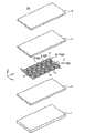
图1是从背面侧观看与本发明有关的实施方式1的太阳能电池组件的主要部分的立体图。FIG. 1 is a perspective view of main parts of a solar cell module according to
图2是图1的太阳能电池组件的主要部分的分解立体图。Fig. 2 is an exploded perspective view of main parts of the solar cell module of Fig. 1 .
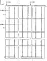
图3是将图2的太阳能电池阵列进行放大而从背面侧观看的放大背面图。FIG. 3 is an enlarged rear view of the solar cell array in FIG. 2 viewed from the rear side.
图4是从背面侧观看为了比较而示出的以往的太阳能电池组件的主要部分的立体图。Fig. 4 is a perspective view of a main part of a conventional solar cell module shown for comparison, viewed from the rear side.
图5是将图4的太阳能电池阵列进行放大而从背面侧观看的放大背面图。FIG. 5 is an enlarged rear view of the solar cell array in FIG. 4 viewed from the rear side.
图6是将与本发明有关的实施方式2的太阳能电池组件的太阳能电池阵列进行放大而从背面侧观看的放大背面图。6 is an enlarged rear view of the solar cell array of the solar cell module according to
图7是将与本发明有关的实施方式3的太阳能电池组件的太阳能电池阵列进行放大而从背面侧观看的放大背面图。7 is an enlarged rear view of the solar cell array of the solar cell module according to
(附图标记说明)(Description of Reference Signs)
1:透光性基板;2:受光面侧密封构件;3:太阳能电池单元;5:背面侧密封构件;6:后板;7:太阳能电池阵列;8:单元间引线;8A:第1单元间引线;8B:第2单元间引线;9、19:列间引线;19a:受光面侧重叠部;19b:背面侧重叠部;10:单元列;10A:第1单元列;10B:第2单元列;50:太阳能电池组件。1: Light-transmitting substrate; 2: Light-receiving surface side sealing member; 3: Solar cell; 5: Rear side sealing member; 6: Rear plate; 7: Solar cell array; 8: Lead wire between cells; 8A: First unit Inter-lead; 8B: 2nd cell lead; 9, 19: row-to-column lead; 19a: light-receiving surface side overlapping portion; 19b: rear side overlapping portion; 10: cell column; 10A: 1st cell column; 10B: 2nd cell Cell column; 50: solar cell module.
具体实施方式Detailed ways
下面根据附图详细地说明与本发明有关的太阳能电池组件及其制造方法的实施方式。此外,并非通过本实施方式来限定本发明。Embodiments of the solar cell module and its manufacturing method related to the present invention will be described in detail below with reference to the accompanying drawings. In addition, this invention is not limited by this embodiment.
实施方式1.
图1是从背面侧观看与本发明有关的实施方式1的太阳能电池组件的主要部分(层叠体)的立体图。图2是图1的太阳能电池组件的主要部分的分解立体图。图3是将图2的太阳能电池阵列进行放大而从背面侧观看的放大背面图。FIG. 1 is a perspective view of a main part (laminated body) of a solar cell module according to
在图1~图3中,构成太阳能电池组件50的主要部分的层叠体是从受光面侧起将由玻璃等透明构件构成的透光性基板1、由透明树脂构成的受光面侧密封构件(第1树脂层)2、对排列为棋盘格状的多个太阳能电池单元3以及串联地连接这些多个太阳能电池单元3的引线8、9进行布线而成的太阳能电池阵列7、由透明树脂构成的背面侧密封构件(第2树脂层)5、以及耐气候性优良的后板6依次进行层叠而构成的。此外,受光面侧密封构件2与背面侧密封构件5通过热处理而成为一体,对太阳能电池阵列7进行树脂密封而形成树脂密封层。这种结构的层叠体的外周缘部的整个一圈被未图示的框架覆盖从而制作太阳能电池组件50。In FIGS. 1 to 3 , the laminated body constituting the main part of the
太阳能电池单元3由厚度为0.16mm~0.3mm程度的单晶硅、多晶硅基板等构成,排列为棋盘格状。在太阳能电池单元3内部形成有PN结,在其受光面和背面设置有电极,而且在受光面设置有反射防止膜。关于太阳能电池单元3的大小,在多晶硅太阳能电池中1个边的长度为150mm~156mm程度。太阳能电池单元3在受光面侧具有受光面电极(正),并在背面侧具有背面电极(负)。The
在太阳能电池阵列7中,多个太阳能电池单元3在第1方向(X方向)上排列而成的单元列10在与第1方向正交的方向(Y方向)上平行地配置有多列。此外,这里将在第1方向上排列的多个单元列10中的相邻的规定的2个单元列作为第1单元列10A与第2单元列10B来进行说明,但是其它的单元列10也是同样的结构。In the solar cell array 7 , a plurality of
将多个太阳能电池单元3进行连接的引线包括:将各个太阳能电池单元3间进行串联连接的多个单元间引线8、以及将利用单元间引线8连接的单元列(太阳能电池单元群)10彼此进行串联连接的多个列间引线9。此外,这里把将形成第1单元列10A的多个太阳能电池单元3进行连接的单元间引线8特别地设为第1单元间引线8A。另外,把将形成第2单元列10B的多个太阳能电池单元3进行连接的单元间引线8特别地设为第2单元间引线8B,但是其它的单元间引线8也是同样的结构。The lead wires for connecting the plurality of
第1单元间引线8A、第2单元间引线8B以及列间引线9由实施了厚度为0.1mm~0.4mm程度的镀锡的扁铜线构成。第1单元间引线8A以及第2单元间引线8B通过锡焊而接合到太阳能电池单元3,将各太阳能电池单元3的背面电极(负)与受光面电极(正)进行电连接。单元间引线8A、8B在太阳能电池组件50的长度方向上将排列为棋盘格状的太阳能电池单元3的背面侧电极与受光面侧电极依次进行连接。在相邻的单元列10中,连接的方向相反。并且,在单元列10的端部中,以使相邻的单元列10的列端的太阳能电池单元3彼此折回的方式连接列间引线9。这样,排列为棋盘格状的太阳能电池单元3全体被串联连接。此外,虽然本实施方式的单元间引线8是连续的一条线,但也可以在太阳能电池单元3的受光面侧与背面侧分割为2条来进行连接。The first
进一步详细进行说明。如上所述,形成第1单元列10A的多个太阳能电池单元3通过多个第1单元间引线8A而被串联连接。多个第1单元间引线8A分别设置在排列为1列的多个太阳能电池单元3的相邻的太阳能电池单元3之间。各个第1单元间引线8A将太阳能电池单元3的受光面电极(正)与背面电极(负)进行连接以使其列具有规定的极性。即,在图2中,将规定的太阳能电池单元3的背面电极与在右侧相邻的太阳能电池单元3的受光面电极进行连接。It demonstrates further in detail. As described above, the plurality of
另一方面,形成第2单元列10B的多个太阳能电池单元3通过多个第2单元间引线8B而被串联连接。多个第2单元间引线8B分别设置在排列为1列的多个太阳能电池单元3的相邻的太阳能电池单元3之间。各个第2单元间引线8B将太阳能电池单元3的受光面电极与背面电极进行连接以使其列具有与第1单元列10A相反的极性。即,在图2中,将规定的太阳能电池单元3的背面电极与在左侧相邻的太阳能电池单元3的受光面电极进行连接。On the other hand, the plurality of
这样连接的第1单元列10A与第2单元列10B在图2的右端通过列间引线9而被连接。即,第1单元列10A的右端的太阳能电池单元3的背面电极与第2单元列10B的右端的太阳能电池单元3的受光面电极通过列间引线9而被连接。这样,所有的太阳能电池单元3被串联连接。并且,作为本实施方式的特点,列间引线9被配置成重叠到第1单元列10A和第2单元列10B的各自图2的右端的太阳能电池单元3。The
说明其它部件的材料等。在透光性基板1中,使用玻璃材料或者聚碳酸酯树脂等合成树脂材料。而且作为玻璃材料,使用白板玻璃(white plate glass)、强化玻璃、热反射玻璃等,一般大多使用厚度为3mm~4mm程度的白板强化玻璃。另一方面,关于聚碳酸酯树脂,大多使用厚度为5mm左右的树脂。Materials and the like of other components will be described. A glass material or a synthetic resin material such as polycarbonate resin is used for the
在受光面侧密封构件2中使用具有透光性、耐热性、电绝缘性、柔软性的原材料,优选以乙烯乙烯基醋酸酯(EVA)、聚乙烯基丁醛(PVB)等为主成分的热可塑性的合成树脂材料。使用厚度为0.6mm~1.0mm程度的薄片状形态的构件。The light-receiving surface
在背面侧密封构件5中使用与受光面侧密封构件2同样地具有透光性、耐热性、电绝缘性、柔软性的原材料,优选以乙烯乙烯基醋酸酯(EVA)、聚乙烯基丁醛(PVB)等为主成分的热可塑性的合成树脂材料。使用厚度为0.4mm~1.0mm程度的薄片状形态的构件。The rear
受光面侧密封构件2和背面侧密封构件5通过气压0.5atm~1.0atm程度的减压下的层压工序来进行热交联(thermallycross linked)而与透光性基板1、太阳能电池阵列7、后板6熔接从而一体化。The light-receiving
后板6使用透湿性、耐气候性、耐加水分解性、绝缘性优良的原材料,使用氟系树脂薄片、蒸镀了氧化铝或者二氧化硅的聚对苯二甲酸乙二醇酯(polyethylene terephthalate,PET)薄片等。The
图4是从背面侧观看为了比较而示出的以往的太阳能电池组件的主要部分的立体图。图5是将图4的太阳能电池阵列进行放大而从背面侧观看的放大背面图。以往的列间引线49在从各单元列10的端部的太阳能电池单元3突出的位置(非发电区域)处连接了第1单元间引线8A以及第2单元间引线8B。因此,与本实施方式相比,太阳能电池组件的外径尺寸变大与单元间引线8A、8B以及列间引线49从太阳能电池单元3突出的部分相应的量。Fig. 4 is a perspective view of a main part of a conventional solar cell module shown for comparison, viewed from the rear side. FIG. 5 is an enlarged rear view of the solar cell array in FIG. 4 viewed from the rear side. In the
根据本实施方式的太阳能电池组件50,将列间引线9在与太阳能电池单元3重叠的位置处配置成从太阳能电池单元3的背面侧延伸到受光面侧。由此,去除列间引线9所占的面积,实现组件外形尺寸的缩小化,从而能够实现部件成本的削减和组件发电效率的提高。According to the
而且还能够缩短将太阳能电池单元3与列间引线9进行连接的第1单元间引线8A以及第2单元间引线8B,能够通过削减电阻损耗来实现组件发电量的提高。Furthermore, the first
实施方式2.
图6是将与本发明有关的实施方式2的太阳能电池组件的太阳能电池阵列进行放大而从背面侧观看的放大背面图。本实施方式的列间引线19与实施方式1的列间引线9相比,向第2单元列10B的太阳能电池单元3的受光面侧延伸而与太阳能电池单元3重叠的受光面侧重叠部19a的宽度变小。另一方面,列间引线19中的向第1单元列10A的太阳能电池单元3的背面侧延伸而与太阳能电池单元3重叠的背面侧重叠部19b的宽度变大。其它的结构与实施方式1相同。6 is an enlarged rear view of the solar cell array of the solar cell module according to
这样,在列间引线19中,通过使位于太阳能电池单元3背面的部分的宽度变大,不会导致组件外形尺寸的增加而能够减小引线的电阻值,通过削减电阻损耗而实现太阳能电池组件的发电量以及发电效率的提高。In this way, in the
另一方面,在列间引线19中,通过使位于太阳能电池单元3表面的部分的宽度变小,能够抑制由于太阳能电池单元3的受光面积的减少所致的组件发电量的降低。On the other hand, in the intercolumn leads 19 , by reducing the width of the portion located on the surface of the
实施方式3.
图7是将与本发明有关的实施方式3的太阳能电池组件的太阳能电池阵列进行放大而从背面侧观看的放大背面图。在本实施方式中,第2单元列10B在第1方向上错开,以使配置列间引线9的一侧的端成为与第1单元列10A的端相比向组件中央侧退缩的位置。并且,列间引线9在第1单元列10A的端部中配置成在太阳能电池单元3的背面侧与太阳能电池单元3重叠,但是在第2单元列10B的端部中没有与太阳能电池单元3重叠。即,本实施方式的列间引线9在太阳能电池单元3的背面侧与太阳能电池单元3重叠,在太阳能电池单元3的受光面侧不与太阳能电池单元3重叠。其它的结构与实施方式1相同。此外,由于图7仅示出太阳能电池阵列的一部分,因此无法进行确认,但是多个单元列10以包括图中未示出的部分在内使整个端部凹凸的方式在第1方向上交替错开地排列。7 is an enlarged rear view of the solar cell array of the solar cell module according to
这样,根据本实施方式的太阳能电池组件,在第1方向上错开地排列以使列间引线9中的向某一方的单元列10的太阳能电池单元3的背面侧延伸的部分与太阳能电池单元3重叠、并且不与另一方的单元列10的太阳能电池单元3重叠,因此组件外形尺寸的缩小化比实施方式1还差,但是能够在维持了太阳能电池单元3的受光面积的状态下减少太阳能电池组件的外形尺寸,能够实现太阳能电池组件发电效率的提高。In this way, according to the solar cell module of the present embodiment, the part of the
如以上那样,与本发明有关的太阳能电池组件适用于在建筑物的屋顶等处设置的太阳能电池组件,特别是适合纵横地排列多个具有受光面电极和背面电极的太阳能电池单元、并利用引线依次连接所相邻的太阳能电池单元的受光面电极和背面电极而成的太阳能电池组件。As described above, the solar cell module related to the present invention is suitable for a solar cell module installed on a roof of a building, etc., and is particularly suitable for arranging a plurality of solar cell cells having a light-receiving surface electrode and a rear electrode A solar cell module in which the light-receiving surface electrodes and the back electrodes of adjacent solar cell cells are sequentially connected.
Claims (4)
Applications Claiming Priority (1)
| Application Number | Priority Date | Filing Date | Title |
|---|---|---|---|
| PCT/JP2009/069056WO2011055457A1 (en) | 2009-11-09 | 2009-11-09 | Solar cell module and method for manufacturing same |
Publications (2)
| Publication Number | Publication Date |
|---|---|
| CN102598306Atrue CN102598306A (en) | 2012-07-18 |
| CN102598306B CN102598306B (en) | 2016-10-26 |
Family
ID=43969700
Family Applications (1)
| Application Number | Title | Priority Date | Filing Date |
|---|---|---|---|
| CN200980162363.2AExpired - Fee RelatedCN102598306B (en) | 2009-11-09 | 2009-11-09 | Solar module and manufacture method thereof |
Country Status (5)
| Country | Link |
|---|---|
| US (1) | US20120222719A1 (en) |
| JP (1) | JP5367090B2 (en) |
| CN (1) | CN102598306B (en) |
| DE (1) | DE112009005354T5 (en) |
| WO (1) | WO2011055457A1 (en) |
Families Citing this family (1)
| Publication number | Priority date | Publication date | Assignee | Title |
|---|---|---|---|---|
| GB2545433B (en)* | 2015-12-15 | 2017-12-20 | Grafmarine | Power generation and cell storage apparatus |
Citations (8)
| Publication number | Priority date | Publication date | Assignee | Title |
|---|---|---|---|---|
| US3819417A (en)* | 1972-05-17 | 1974-06-25 | Communications Satellite Corp | Mechanically interlaced and electrically interconnected silicon solar cells |
| US4433200A (en)* | 1981-10-02 | 1984-02-21 | Atlantic Richfield Company | Roll formed pan solar module |
| JPH02295174A (en)* | 1989-05-09 | 1990-12-06 | Mitsubishi Electric Corp | Solar cell module |
| US20020056473A1 (en)* | 2000-11-16 | 2002-05-16 | Mohan Chandra | Making and connecting bus bars on solar cells |
| US20030062078A1 (en)* | 1998-03-13 | 2003-04-03 | Canon Kabushiki Kaisha | Photovoltaic module, photovoltaic module array, photovoltaic system, and method of detecting failure of photovoltaic module |
| JP2006278904A (en)* | 2005-03-30 | 2006-10-12 | Sanyo Electric Co Ltd | SOLAR CELL MODULE AND SOLAR CELL DEVICE HAVING THE SAME |
| CN101047211A (en)* | 2006-03-31 | 2007-10-03 | 三洋电机株式会社 | Solar battery array |
| JP2008235819A (en)* | 2007-03-23 | 2008-10-02 | Sanyo Electric Co Ltd | Solar cell module |
Family Cites Families (8)
| Publication number | Priority date | Publication date | Assignee | Title |
|---|---|---|---|---|
| DE3308269A1 (en)* | 1983-03-09 | 1984-09-13 | Licentia Patent-Verwaltungs-Gmbh | SOLAR CELL |
| JP4526223B2 (en)* | 2001-06-29 | 2010-08-18 | シャープ株式会社 | Wiring member, solar cell module and manufacturing method thereof |
| JP4817619B2 (en)* | 2004-06-30 | 2011-11-16 | 京セラ株式会社 | Solar cell module |
| JP4493485B2 (en)* | 2004-04-28 | 2010-06-30 | シャープ株式会社 | Wiring member for solar cell module, solar cell module using the same, and manufacturing method of wiring member for solar cell module |
| JP2007294866A (en)* | 2006-03-31 | 2007-11-08 | Sanyo Electric Co Ltd | Solar cell module |
| JP2008300449A (en)* | 2007-05-29 | 2008-12-11 | Sanyo Electric Co Ltd | Solar cell module and manufacturing method thereof |
| US20090139557A1 (en)* | 2007-11-30 | 2009-06-04 | Douglas Rose | Busbar connection configuration to accommodate for cell misalignment |
| CN102439722A (en)* | 2009-05-25 | 2012-05-02 | 达伊4能量有限公司 | Photovoltaic module string arrangement and shading protection thereof |
- 2009
- 2009-11-09CNCN200980162363.2Apatent/CN102598306B/ennot_activeExpired - Fee Related
- 2009-11-09WOPCT/JP2009/069056patent/WO2011055457A1/enactiveApplication Filing
- 2009-11-09DEDE112009005354Tpatent/DE112009005354T5/ennot_activeWithdrawn
- 2009-11-09USUS13/508,705patent/US20120222719A1/ennot_activeAbandoned
- 2009-11-09JPJP2011539242Apatent/JP5367090B2/ennot_activeExpired - Fee Related
Patent Citations (8)
| Publication number | Priority date | Publication date | Assignee | Title |
|---|---|---|---|---|
| US3819417A (en)* | 1972-05-17 | 1974-06-25 | Communications Satellite Corp | Mechanically interlaced and electrically interconnected silicon solar cells |
| US4433200A (en)* | 1981-10-02 | 1984-02-21 | Atlantic Richfield Company | Roll formed pan solar module |
| JPH02295174A (en)* | 1989-05-09 | 1990-12-06 | Mitsubishi Electric Corp | Solar cell module |
| US20030062078A1 (en)* | 1998-03-13 | 2003-04-03 | Canon Kabushiki Kaisha | Photovoltaic module, photovoltaic module array, photovoltaic system, and method of detecting failure of photovoltaic module |
| US20020056473A1 (en)* | 2000-11-16 | 2002-05-16 | Mohan Chandra | Making and connecting bus bars on solar cells |
| JP2006278904A (en)* | 2005-03-30 | 2006-10-12 | Sanyo Electric Co Ltd | SOLAR CELL MODULE AND SOLAR CELL DEVICE HAVING THE SAME |
| CN101047211A (en)* | 2006-03-31 | 2007-10-03 | 三洋电机株式会社 | Solar battery array |
| JP2008235819A (en)* | 2007-03-23 | 2008-10-02 | Sanyo Electric Co Ltd | Solar cell module |
Also Published As
| Publication number | Publication date |
|---|---|
| JP5367090B2 (en) | 2013-12-11 |
| JPWO2011055457A1 (en) | 2013-03-21 |
| US20120222719A1 (en) | 2012-09-06 |
| DE112009005354T5 (en) | 2012-11-22 |
| CN102598306B (en) | 2016-10-26 |
| WO2011055457A1 (en) | 2011-05-12 |
Similar Documents
| Publication | Publication Date | Title |
|---|---|---|
| CN101779297B (en) | Solar cell module | |
| CN105870216B (en) | A kind of connection structure with transparent electrode crystal silicon photovoltaic cell | |
| TWI413266B (en) | Solar battery module | |
| CN102959723B (en) | Solar module and manufacture method thereof | |
| TWI495124B (en) | Solar cell and solar cell module | |
| CN209708996U (en) | An anti-hot spot ultra-dense photovoltaic module | |
| WO2019214627A1 (en) | Solar cell string, string group, assembly, and manufacturing method thereof | |
| JP5714080B2 (en) | Solar cell module | |
| JP5927437B2 (en) | Solar cell module | |
| JPWO2010122935A1 (en) | Wiring sheet, solar cell with wiring sheet and solar cell module | |
| JP2009081205A (en) | Solar battery module | |
| CN111613683B (en) | Photovoltaic modules | |
| CN102113126A (en) | Daylighting solar cell module | |
| CN106449798A (en) | Double-side light-inlet crystal silicon photovoltaic module and manufacturing method thereof | |
| JP5637089B2 (en) | Solar cell module | |
| CN203423207U (en) | Solar cell module | |
| JP2008300449A (en) | Solar cell module and manufacturing method thereof | |
| CN120343989A (en) | Back contact photovoltaic module | |
| JP7530221B2 (en) | Solar cell strings and solar cell modules | |
| CN102598306B (en) | Solar module and manufacture method thereof | |
| JP2013093610A (en) | Solar cell structure and solar cell module | |
| CN206322708U (en) | A kind of two-sided entering light crystalline silicon photovoltaic module | |
| CN111564514B (en) | A P/N type double-layer solar cell double-sided module | |
| JP2008053303A (en) | Solar cell panel | |
| CN110854224A (en) | Solar photovoltaic module and assembling method thereof |
Legal Events
| Date | Code | Title | Description |
|---|---|---|---|
| C06 | Publication | ||
| PB01 | Publication | ||
| C10 | Entry into substantive examination | ||
| SE01 | Entry into force of request for substantive examination | ||
| C14 | Grant of patent or utility model | ||
| GR01 | Patent grant | ||
| CF01 | Termination of patent right due to non-payment of annual fee | Granted publication date:20161026 Termination date:20211109 | |
| CF01 | Termination of patent right due to non-payment of annual fee |