CN102593885A - Smart powering, pairing system and method, and power conversion unit - Google Patents
Smart powering, pairing system and method, and power conversion unitDownload PDFInfo
- Publication number
- CN102593885A CN102593885ACN2012100041604ACN201210004160ACN102593885ACN 102593885 ACN102593885 ACN 102593885ACN 2012100041604 ACN2012100041604 ACN 2012100041604ACN 201210004160 ACN201210004160 ACN 201210004160ACN 102593885 ACN102593885 ACN 102593885A
- Authority
- CN
- China
- Prior art keywords
- pcu
- electronic equipment
- pairing
- power
- electronic
- Prior art date
- Legal status (The legal status is an assumption and is not a legal conclusion. Google has not performed a legal analysis and makes no representation as to the accuracy of the status listed.)
- Granted
Links
Images
Classifications
- G—PHYSICS
- G06—COMPUTING OR CALCULATING; COUNTING
- G06F—ELECTRIC DIGITAL DATA PROCESSING
- G06F1/00—Details not covered by groups G06F3/00 - G06F13/00 and G06F21/00
- G06F1/26—Power supply means, e.g. regulation thereof
- B—PERFORMING OPERATIONS; TRANSPORTING
- B63—SHIPS OR OTHER WATERBORNE VESSELS; RELATED EQUIPMENT
- B63B—SHIPS OR OTHER WATERBORNE VESSELS; EQUIPMENT FOR SHIPPING
- B63B1/00—Hydrodynamic or hydrostatic features of hulls or of hydrofoils
- B63B1/16—Hydrodynamic or hydrostatic features of hulls or of hydrofoils deriving additional lift from hydrodynamic forces
- B—PERFORMING OPERATIONS; TRANSPORTING
- B64—AIRCRAFT; AVIATION; COSMONAUTICS
- B64C—AEROPLANES; HELICOPTERS
- B64C3/00—Wings
- B64C3/38—Adjustment of complete wings or parts thereof
- G—PHYSICS
- G06—COMPUTING OR CALCULATING; COUNTING
- G06F—ELECTRIC DIGITAL DATA PROCESSING
- G06F1/00—Details not covered by groups G06F3/00 - G06F13/00 and G06F21/00
- G06F1/16—Constructional details or arrangements
- G06F1/1613—Constructional details or arrangements for portable computers
- G06F1/1632—External expansion units, e.g. docking stations
- H—ELECTRICITY
- H04—ELECTRIC COMMUNICATION TECHNIQUE
- H04M—TELEPHONIC COMMUNICATION
- H04M1/00—Substation equipment, e.g. for use by subscribers
- H04M1/72—Mobile telephones; Cordless telephones, i.e. devices for establishing wireless links to base stations without route selection
- H04M1/724—User interfaces specially adapted for cordless or mobile telephones
- H04M1/72403—User interfaces specially adapted for cordless or mobile telephones with means for local support of applications that increase the functionality
- H04M1/72409—User interfaces specially adapted for cordless or mobile telephones with means for local support of applications that increase the functionality by interfacing with external accessories
- H04M1/72412—User interfaces specially adapted for cordless or mobile telephones with means for local support of applications that increase the functionality by interfacing with external accessories using two-way short-range wireless interfaces
- H—ELECTRICITY
- H10—SEMICONDUCTOR DEVICES; ELECTRIC SOLID-STATE DEVICES NOT OTHERWISE PROVIDED FOR
- H10F—INORGANIC SEMICONDUCTOR DEVICES SENSITIVE TO INFRARED RADIATION, LIGHT, ELECTROMAGNETIC RADIATION OF SHORTER WAVELENGTH OR CORPUSCULAR RADIATION
- H10F19/00—Integrated devices, or assemblies of multiple devices, comprising at least one photovoltaic cell covered by group H10F10/00, e.g. photovoltaic modules
- H—ELECTRICITY
- H02—GENERATION; CONVERSION OR DISTRIBUTION OF ELECTRIC POWER
- H02J—CIRCUIT ARRANGEMENTS OR SYSTEMS FOR SUPPLYING OR DISTRIBUTING ELECTRIC POWER; SYSTEMS FOR STORING ELECTRIC ENERGY
- H02J7/00—Circuit arrangements for charging or depolarising batteries or for supplying loads from batteries
- H02J7/00032—Circuit arrangements for charging or depolarising batteries or for supplying loads from batteries characterised by data exchange
- H02J7/00034—Charger exchanging data with an electronic device, i.e. telephone, whose internal battery is under charge
- H—ELECTRICITY
- H02—GENERATION; CONVERSION OR DISTRIBUTION OF ELECTRIC POWER
- H02J—CIRCUIT ARRANGEMENTS OR SYSTEMS FOR SUPPLYING OR DISTRIBUTING ELECTRIC POWER; SYSTEMS FOR STORING ELECTRIC ENERGY
- H02J7/00—Circuit arrangements for charging or depolarising batteries or for supplying loads from batteries
- H02J7/02—Circuit arrangements for charging or depolarising batteries or for supplying loads from batteries for charging batteries from AC mains by converters
- H—ELECTRICITY
- H04—ELECTRIC COMMUNICATION TECHNIQUE
- H04L—TRANSMISSION OF DIGITAL INFORMATION, e.g. TELEGRAPHIC COMMUNICATION
- H04L63/00—Network architectures or network communication protocols for network security
- H04L63/08—Network architectures or network communication protocols for network security for authentication of entities
- H04L63/0869—Network architectures or network communication protocols for network security for authentication of entities for achieving mutual authentication
- H—ELECTRICITY
- H04—ELECTRIC COMMUNICATION TECHNIQUE
- H04M—TELEPHONIC COMMUNICATION
- H04M1/00—Substation equipment, e.g. for use by subscribers
- H04M1/60—Substation equipment, e.g. for use by subscribers including speech amplifiers
- H04M1/6033—Substation equipment, e.g. for use by subscribers including speech amplifiers for providing handsfree use or a loudspeaker mode in telephone sets
- H04M1/6041—Portable telephones adapted for handsfree use
- H04M1/6058—Portable telephones adapted for handsfree use involving the use of a headset accessory device connected to the portable telephone
- H04M1/6066—Portable telephones adapted for handsfree use involving the use of a headset accessory device connected to the portable telephone including a wireless connection
- Y—GENERAL TAGGING OF NEW TECHNOLOGICAL DEVELOPMENTS; GENERAL TAGGING OF CROSS-SECTIONAL TECHNOLOGIES SPANNING OVER SEVERAL SECTIONS OF THE IPC; TECHNICAL SUBJECTS COVERED BY FORMER USPC CROSS-REFERENCE ART COLLECTIONS [XRACs] AND DIGESTS
- Y02—TECHNOLOGIES OR APPLICATIONS FOR MITIGATION OR ADAPTATION AGAINST CLIMATE CHANGE
- Y02D—CLIMATE CHANGE MITIGATION TECHNOLOGIES IN INFORMATION AND COMMUNICATION TECHNOLOGIES [ICT], I.E. INFORMATION AND COMMUNICATION TECHNOLOGIES AIMING AT THE REDUCTION OF THEIR OWN ENERGY USE
- Y02D30/00—Reducing energy consumption in communication networks
- Y02D30/70—Reducing energy consumption in communication networks in wireless communication networks
- Y—GENERAL TAGGING OF NEW TECHNOLOGICAL DEVELOPMENTS; GENERAL TAGGING OF CROSS-SECTIONAL TECHNOLOGIES SPANNING OVER SEVERAL SECTIONS OF THE IPC; TECHNICAL SUBJECTS COVERED BY FORMER USPC CROSS-REFERENCE ART COLLECTIONS [XRACs] AND DIGESTS
- Y02—TECHNOLOGIES OR APPLICATIONS FOR MITIGATION OR ADAPTATION AGAINST CLIMATE CHANGE
- Y02E—REDUCTION OF GREENHOUSE GAS [GHG] EMISSIONS, RELATED TO ENERGY GENERATION, TRANSMISSION OR DISTRIBUTION
- Y02E10/00—Energy generation through renewable energy sources
- Y02E10/50—Photovoltaic [PV] energy
Landscapes
- Engineering & Computer Science (AREA)
- Theoretical Computer Science (AREA)
- Physics & Mathematics (AREA)
- Mechanical Engineering (AREA)
- Human Computer Interaction (AREA)
- Computer Networks & Wireless Communication (AREA)
- Fluid Mechanics (AREA)
- General Physics & Mathematics (AREA)
- General Engineering & Computer Science (AREA)
- Aviation & Aerospace Engineering (AREA)
- Ocean & Marine Engineering (AREA)
- Computer Hardware Design (AREA)
- Combustion & Propulsion (AREA)
- Chemical & Material Sciences (AREA)
- Signal Processing (AREA)
- Selective Calling Equipment (AREA)
- Power Sources (AREA)
- Mobile Radio Communication Systems (AREA)
- Charge And Discharge Circuits For Batteries Or The Like (AREA)
- Remote Monitoring And Control Of Power-Distribution Networks (AREA)
- Near-Field Transmission Systems (AREA)
- Cable Transmission Systems, Equalization Of Radio And Reduction Of Echo (AREA)
Abstract
Description
Translated fromChinese技术领域technical field
本发明通常涉及电子设备和系统。更具体地,本发明涉及电子设备和系统的电力输送。The present invention generally relates to electronic devices and systems. More specifically, the present invention relates to power delivery for electronic devices and systems.
背景技术Background technique
个人电子设备的使用渗透到日常生活的各个方面。很多这样的设备经常性的处于待机模式,这种模式的累加效应和设备数量的不断增加对于现有能源来说是一个沉重的负担。再者,随着市场上出现的越来越多的功能创新,实现这些功能所带来的复杂性经常会超过它们所提供的便利性。The use of personal electronic devices permeates every aspect of everyday life. Many of these devices are constantly in standby mode, and the cumulative effect of this mode and the increasing number of devices is a heavy burden on the available energy sources. Furthermore, as more and more functional innovations appear on the market, the complexity of implementing these functions often outweighs the convenience they provide.
上述功能之一是将一个电子设备与一个或多个其它电子设备进行配对的行为,从而在一个设备不需要始终包含需要的所有功能的情况下结合各功能。尽管分布式功能开发出许多需要组合的新功能,但使能这种组合功能的配对设备会带来很多单独的手动操作步骤,利用新技术来完成的这些手动步骤可能需要超出一般的方便程度。One of the aforementioned functions is the act of pairing one electronic device with one or more other electronic devices, combining functions without one device needing to contain all the functions needed at all times. While distributed functionality develops many new capabilities that need to be combined, pairing devices to enable this combined functionality introduces many separate manual steps that may require more than a normal level of convenience to accomplish with new technology.
此外,可能仅为了降低制造成本,电子设备的传统电源一般为不可配置并缺乏功能,但也可能是通常的安全性和可靠性考虑使制造商朝着将他们的电源设计得在物理层面上各不相同,从而限制由于不兼容的电压和电流规范带来的损伤风险。由于各个电源一般设计成在有限时间内(例如,单个产品的使用寿命)为很有限的市场服务,总的来说,没有足够的诱因为每个重复的普通电源设计高效或便利功能。另外,在便携式电子设备的情况下,互换性的缺乏通常导致消费者具有多个收集的电源,例如,在家和工作的地方,这样会增加传统电源和供电系统通常意义上的浪费和不方便性。Furthermore, traditional power supplies for electronic equipment are generally non-configurable and lack functionality, perhaps simply to reduce manufacturing costs, but it may also be that general safety and reliability considerations drive manufacturers toward designing their power supplies to be physically separate different, thereby limiting the risk of damage due to incompatible voltage and current specifications. Since individual power supplies are generally designed to serve a very limited market for a limited period of time (eg, the lifetime of a single product), there is generally not enough incentive to design efficient or convenient functions into each duplicate common power supply. Additionally, in the case of portable electronic devices, the lack of interchangeability often results in consumers having multiple collections of power sources, for example, at home and at work, which adds waste and inconvenience in the usual sense to traditional power and power delivery systems sex.
因此,有必要在所属技术领域通过提供供电系统克服上述缺点和不足,所述供电系统可在增加使用那些电子设备的便利性的同时容易地适用于高效和精确地为各种电子设备供电。Therefore, there is a need in the art to overcome the above disadvantages and deficiencies by providing a power supply system that can be easily adapted to efficiently and accurately power various electronic devices while increasing the convenience of using those electronic devices.
发明内容Contents of the invention
如至少一幅附图所示和/或结合至少一幅附图所描述,如权利要求中所更完整阐述的,本发明涉及智能供电和配对系统以及相关方法。As shown in and/or described in connection with at least one of the accompanying drawings, the present invention relates to an intelligent powering and pairing system and related methods as more fully set forth in the claims.
根据本发明的一个方面,提供一种智能供电和配对系统,包括:According to one aspect of the present invention, an intelligent power supply and pairing system is provided, including:
用于为多个电子设备供电的电源变换单元(PCU);Power Conversion Unit (PCU) for powering multiple electronic devices;
所述PCU还用于与所述多个电子设备的至少两个进行通信并将其配对。The PCU is also configured to communicate with and pair with at least two of the plurality of electronic devices.
优选地,所述PCU用于从所述多个电子设备的至少一个接收电源管理参数,所述电源管理参数用来调节向所述多个电子设备的至少一个所提供的电源的输出功率特征。Preferably, the PCU is configured to receive a power management parameter from at least one of the plurality of electronic devices, the power management parameter is used to adjust an output power characteristic of a power supply provided to the at least one of the plurality of electronic devices.
优选地,所述PCU还用于配对所述多个电子设备的至少两个,以使它们利用安全通信协议通过所述PCU进行通信。Preferably, said PCU is further configured to pair at least two of said plurality of electronic devices such that they communicate through said PCU using a secure communication protocol.
优选地,所述PCU用于从所述多个电子设备的至少两个的其中一个接收配对信息。Preferably, the PCU is configured to receive pairing information from one of at least two of the plurality of electronic devices.
优选地,所述PCU用于在一段时间内保存所述配对信息。Preferably, the PCU is configured to save the pairing information for a period of time.
优选地,所述PCU用于保存所述配对信息直到事件发生。Preferably, the PCU is configured to save the pairing information until an event occurs.
优选地,所述配对信息包含身份描述。Preferably, the pairing information includes an identity description.
优选地,所述配对信息包含安全数据。Preferably, said pairing information includes security data.
根据本发明的其他方面,提供在智能供电和配对系统中使用的电源变换单元(PCU),所述PCU包括:According to other aspects of the present invention, a power conversion unit (PCU) used in an intelligent power supply and pairing system is provided, the PCU includes:
通信模块;communication module;
电源管理模块(PMM);Power Management Module (PMM);
配对模块;pairing module;
所述通信模块和所述PMM用于与多个电子设备进行通信并给它们供电;The communication module and the PMM are used to communicate with and supply power to a plurality of electronic devices;
所述通信模块和所述配对模块用于与所述多个电子设备的至少两个进行通信和对其进行配对。The communication module and the pairing module are for communicating with and pairing with at least two of the plurality of electronic devices.
优选地,所述PMM用于通过有线电力管道(power conduit)给所述多个电子设备的至少一个进行供电。Preferably, the PMM is configured to provide power to at least one of the plurality of electronic devices through a wired power conduit.
优选地,所述通信模块用于通过电力管道形成的通信信道与所述多个电子设备的至少一个进行通信。Preferably, the communication module is configured to communicate with at least one of the plurality of electronic devices through a communication channel formed by a power conduit.
优选地,所述通信模块用于通过独立于电力管道形成的无线通信信道与所述多个电子设备的至少一个进行通信。Advantageously, the communication module is configured to communicate with at least one of the plurality of electronic devices via a wireless communication channel formed independently of the power conduit.
优选地,所述配对模块包括用来使能所述配对模块的物理认证装置。Advantageously, said pairing module includes physical authentication means for enabling said pairing module.
优选地,所述物理认证装置是指纹采集器。Preferably, said physical authentication device is a fingerprint reader.
优选地,所述物理认证装置是电子密匙卡检测器。Preferably, said physical authentication device is an electronic key fob detector.
根据其他方面,提供一种方法,所述方法由对第一电子设备与第二电子设备进行配对的电源变换单元(PCU)所使用,所述PCU有用于执行所述方法的控制器,所述方法包括:According to other aspects, there is provided a method for use by a power conversion unit (PCU) for pairing a first electronic device with a second electronic device, the PCU having a controller for performing the method, the Methods include:
检测所述第一电子设备与所述PCU间的电源连接(power connection);detecting a power connection (power connection) between the first electronic device and the PCU;
建立所述第一电子设备与所述PCU间的第一通信链路;establishing a first communication link between the first electronic device and the PCU;
通过所述PCU从所述第一电子设备接收配对信息;receiving pairing information from the first electronic device through the PCU;
建立所述第二电子设备与所述PCU间的第二通信链路;establishing a second communication link between the second electronic device and the PCU;
利用所述配对信息对所述第二电子设备与所述第一电子设备进行配对。pairing the second electronic device with the first electronic device by using the pairing information.
优选地,所述配对信息包含身份描述,所述PCU用于利用所述身份描述区分所述第二电子设备与多个其它电子设备。Preferably, the pairing information includes an identity description, and the PCU uses the identity description to distinguish the second electronic device from multiple other electronic devices.
优选地,所述配对信息包含安全数据,所述PCU用于利用所述安全数据对所述第二电子设备与所述第一电子设备进行配对。Preferably, the pairing information includes security data, and the PCU uses the security data to pair the second electronic device with the first electronic device.
优选地,本方法还包括:Preferably, the method also includes:
接收解除所述第一和第二电子设备彼此间配对的指令;receiving an instruction to unpair the first and second electronic devices from each other;
解除所述第一电子设备和所述第二电子设备的配对。unpairing the first electronic device and the second electronic device.
附图说明Description of drawings
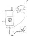
图1是根据本发明一个实施例的、智能供电和配对系统的模块示意图;FIG. 1 is a block diagram of an intelligent power supply and pairing system according to an embodiment of the present invention;
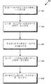
图2是根据本发明实施例的、阐述实现电子设备配对方法的步骤的流程图。Fig. 2 is a flow chart illustrating the steps of implementing a method for pairing an electronic device according to an embodiment of the present invention.
具体实施方式Detailed ways
本发明涉及智能供电和配对系统以及相关方法。以下的描述包含关于本发明实施方式的具体信息。本领域技术人员应认识到,本发明可由与本申请的特定论述不同的方式来实现。另外,为了使对本发明的理解更加清晰、明确,忽略了对本发明的一些具体细节的论述。The present invention relates to intelligent power supply and pairing systems and related methods. The following description contains specific information pertaining to embodiments of the invention. Those skilled in the art will recognize that the present invention may be practiced otherwise than as specifically discussed in this application. In addition, in order to make the understanding of the present invention clearer and clearer, some specific details of the present invention are omitted.
本申请的附图和它们的附属详细描述仅仅涉及本发明的示例性实施例。简而言之,本申请和附图并没有对本发明的其它实施例进行具体描述。应理解的是,除非特别注明,否则附图中相似或相应元件能以相似或相应的标号标记。而且,本申请的附图和说明普遍不是按照比例,也不是为了与实际的相对尺寸相一致。The drawings in this application and their accompanying detailed description relate to merely exemplary embodiments of the invention. In short, other embodiments of the invention are not specifically described in the application and drawings. It should be understood that unless otherwise noted, like or corresponding elements in the drawings may be marked with like or corresponding reference numerals. Furthermore, the drawings and descriptions of the present application are generally not to scale, nor are they intended to correspond to actual relative dimensions.
许多现代电子设备具有与其它设备通信的能力,目的是提高它们的使用便利性。为了减少串音和/或安全传递信息,可能以使它们的通信和与其他设备的通信可区分的方式“配对”或集合电子设备。当配对成为结合多个电子设备功能的重要方式时,特别是随着电子设备本身变得更复杂,对一个设备和另一设备配对的最初步骤可能是复杂的、耗时的并且极其地不方便。Many modern electronic devices have the ability to communicate with other devices in order to increase their ease of use. To reduce crosstalk and/or to transfer information securely, it is possible to "pair" or group electronic devices in such a way that their communications are distinguishable from those of other devices. When pairing becomes an important way to combine the functionality of multiple electronic devices, especially as electronic devices themselves become more complex, the initial steps of pairing one device with another can be complex, time-consuming and extremely inconvenient .
由于传统的电力输送系统一般不可普遍使用,所以它们不适合于解决上述不方便性。当一般的电子设备的使用寿命结束时,由于它的电力输送系统不能结合其他电子设备运行,通常单纯地丢弃它的电力输送系统。知道这点,制造商通常把它们的电力输送系统做得尽量便宜,这样会排除向他们的设计中并入任何重要的便利功能。Since conventional power delivery systems are generally not generally available, they are not well suited to address the above inconveniences. When a typical electronic device reaches the end of its useful life, its power delivery system is often simply discarded because it cannot operate in conjunction with other electronic devices. Knowing this, manufacturers typically make their power delivery systems as cheap as possible, which precludes incorporating any significant convenience features into their designs.
图1是本发明的一个实施例的模块图,本发明能够克服常规技术的缺点和不足。图1中的智能电源管理系统100包括电子设备120和130、电源变换单元(PCU)110和有线电力管道116。根据图1所示的实施例,PCU 110可用于利用干线适配器(mains adapter)111、通过标准的壁装式电插座连接干线交流(AC)电源线,并通过有线电力通道116给电子设备120或130供电。Fig. 1 is a block diagram of an embodiment of the present invention, and the present invention can overcome the shortcomings and deficiencies of conventional technologies. Intelligent
如图1所示,有线电力管道116可与PCU 110通过连接器117(例如通过通用串行总线(USB)接口插接式连接器)连接,所述连接器可以是固定连接器或可拆式模块化连接器。有线电力管道116可通过模块化连接器118连接PCU 110与电子设备120或130,例如,所述模块化连接器可以是小型USB连接器或任何适合于在有线电力管道116与接收电源的电子设备或系统间提供接口的模块化连接器。有线电力管道116可充当PCU 110与电子设备120或130间的电力传递连接,并可用于传递电力来操作电子设备和/或对它们的电池进行充电(例如,电子设备120的电池122或电子设备130的电池132)。As shown in FIG. 1 ,
虽然图1所示的实施例展示了一次只与一个电子设备(例如,电子设备120或130)连接的PCU 110,但是该描述仅作为实例而提供。更通常地,例如,通过包含基本上同时连接每个设备与PCU 110的多个电力管道,PCU 110可用于给多个各个单独的电子设备和/或系统供电,这些电子设备和/或系统的每个都有它们自己的具体电源要求。替代性地,PCU 110可用于给多个电子设备的任何一个提供可变输出,但是一次只能结合单个电子设备或系统这样做。然而,在任何实施方式中,PCU 110可用于支持它本身和与它连接的电子设备或系统间的通信信道。Although the embodiment shown in FIG. 1 shows the
如图1所示,根据智能电源管理系统100的实施例,PCU 110包括通信模块112、电源管理模块(PMM)114和配对模块115。例如,通信模块112可用于通过建立在PCU 110与电子设备120或130间的通信信道在PCU 110与电子设备120或130间发送和接收信息(例如,状态信息、电源管理参数和/或配对信息)。As shown in FIG. 1 , according to an embodiment of an intelligent
如图1所示的实施例,其中电力通过有线连接(例如,有线电力管道116)从PCU 110传递至电子设备120。所述有线连接亦可提供信息传递的通信信道。在不同的实施例中,例如,电力可通过本领域中已知的电感耦合或共振电感耦合的无线电力管道(图1中未显示)进行传递。在这些实施例中,通信模块112可用于将无线电力管道用作无线通信信道。通过蓝牙、蓝牙LE、WiFi、近场通信(NFC)、或其它适合的无线通信协议,通信模块112还可能以对通过电力管道形成的通信信道附加或替代的方式、用于支持电子设备120和130单独的无线通信信道。1, where power is delivered from the
例如,PMM 114可包括具有多个数字和模拟输入/输出端口的微控制器,所述输入/输出端口与通信模块112以及与本领域中已知的可编程可变电源连接。出于有效地和精确地给电子设备120或130供电或对它们各自的电池122或132充电的目的,例如,PMM 114可用于利用从通信模块112接收到的信息来动态调整输送至电子设备120或130的电源的输出功率特征(例如,电流和电压电平)。通过检测测量的跨过电力管道的输出阻抗的变化,PMM 114也可用于检测与电子设备的电源连接。For example,
在一个例子中,根据电子设备120与PCU 110间通过通信信道交换的信息(例如,电源管理参数),通信模块112和PMM 114的复合作用可用于使能PMM 114调整输送至电子设备120的电源的输出功率特征。因此,本发明的实施例可用来给许多不同的电子设备供电,从而显著延长PCU 110的使用寿命并减少对多个常规配套电源的需要。In one example, the combined action of
例如,配对模块115可包括具有多个数字和模拟输入/输出端口的微控制器,所述输入/输出端口与通信模块112以及和本领域中已知的数据存储设备(例如,闪存设备或静态随机存取存储器组)连接。当电子设备(例如,电子设备120和130)与PCU 110进行通信时,例如,配对模块115可用于利用从通信模块112接收到的配对信息对电子设备进行配对。一旦配对完成,如本领域中已知的,例如,电子设备120和130可用于与彼此安全、专有和/或透明地通信(例如,在没有来自用户或PCU 110的额外帮助的情况下)。上述后配对(post-pairing)配置可由包含配对模块115接收到的一部分配对信息的指令来定义,并且所述后配对配置可用来对电子设备120和130进行配对。配对模块115亦可用于保存所有上述配对信息和/或其它的传输信息,其用于配对其他电子设备时的后续使用。For example,
替代性地或除上述以外,配对模块115也可包括图1中未显示的物理认证设备,该物理认证设备可用于使能或禁用配对模块115的配对功能。例如,物理认证设备可包含指纹扫描器或电子密匙卡检测器,如本领域中已知的,该检测器可用于识别显示特定电子签名的电子密匙卡。配对模块115可用于在配对模块115成功认证后暂时使能配对功能,例如,当扫描的指纹与之前存储在配对模块115中的另一指纹匹配时,或当PCU 110检测到特定电子密匙卡存在时。Alternatively or in addition to the above, the
虽然没有在图1中显示,PCU 110亦可包含各种用户交互设备,例如,可与包含PCU 110的任何模块连接的发光状态指示器(lighted status indicator)或物理开关。例如,发光状态指示器可包含彩色发光二极管(LED)或一条LEDs带,其用于表明通信模块114的通信链路状态或配对模块115的失败认证。例如,物理开关可包含瞬时按钮开关,例如,该瞬时按钮开关可用于通知配对模块115由于已配对的设备丢失或失效,必须采用新配对信息重启配对功能。Although not shown in FIG. 1 ,
图2是流程图,该流程图描述了根据本发明实施例的对电子设备和另一电子设备进行配对的方法。在流程图200中省略对本领域普通技术人员而言显而易见的某些细节和特征。例如,如本领域中已知的,步骤可能包含一个或多个子步骤、或者可能涉及到专门的设备或原料。流程图200中表明的步骤201至205足够对本发明的一个实施例进行充分描述;然而,本发明的其它实施例可利用与流程图200中所示的那些不同的步骤来实现。Fig. 2 is a flowchart describing a method for pairing an electronic device with another electronic device according to an embodiment of the present invention. Certain details and features that would be apparent to one of ordinary skill in the art are omitted from
现在参照图2中包含的本方法的步骤201,流程图200的步骤201包含检测第一电子设备和PCU间的电源连接。例如,所述第一电子设备可以为任何能与PCU进行通信和与其它电子设备配对的电子设备,并且该设备可能有或者可能没有内部储能装置,譬如电池。所述PCU包含通信模块、PMM和配对模块,并且可用于从干线适配器获取电源,例如上述图1中的PCU 110。如上所述,所述PCU的PMM可用于检测通过电力管道的输出阻抗的变化和检测与PCU的电源连接。Referring now to step 201 of the method contained in FIG. 2 , step 201 of
继续图2中的步骤202,流程图200的步骤202包含在第一电子设备和PCU间建立第一通信链路。所述第一通信链路可能通过有线或无线电力管道、有线或无线通信信道、或那些的任意结合而形成,并且所述通信链路可由与配对模块和/或PMM协同运行的通信模块来建立。Continuing with
现在转至图2中的步骤203,流程图200的步骤203包含PCU从第一电子设备接收配对信息。基于如步骤202中描述的已建立的通信链路,通过发射用来区别待配对设备与其它设备的身份描述,或者通过请求数字认证密匙或其它安全数据,PCU或电子设备可启动配对信息的传递。身份描述可包含电子设备的序列号、通用产品代码(UPC)、网络地址、制造商、型号、或其它可将一个或多个电子设备与其他电子设备区分开的数字、符号或文本的集合。另一方面,如本领域中已知的,安全数据可包含可将一个或多个电子设备的通信与其他通信区分开的任何数据、或者通常可用于确保通信的数据。例如,配对信息传递可透明(transparently)开始(例如,没有用户的任何干涉)。此外,PCU接收的任何配对信息可存储在上述PCU的配对模块中。Turning now to step 203 in FIG. 2 , step 203 of
继续图2中的步骤204,流程图200的步骤204包含在第二电子设备与PCU间建立第二通信链路。所述第二通信链路可完全独立于第一通信链路,并且像第一通信链路一样,可以通过有线或无线电力管道、有线或无线通信信道、或那些的任一结合而形成。例如,第二通信链路可由与配对模块和/或PMM协同运行的通信模块来建立,并且可与第一通信链路大致同时运作。Continuing with
现在转至图2中的步骤205,流程图200的步骤205包含利用配对信息对第二电子设备与第一电子设备进行配对。配对可透明发生,并可持续或可能不能持续延长的一段时间。例如,如上所述,如果由第一电子设备发射至PCU的配对信息包含身份描述,PCU的配对模块会向第二设备请求身份描述,并且把它与第一设备发射的身份描述的储存版本进行对比。如果身份描述相匹配,例如,PCU能通过向两个设备发射PCU生成的安全数据(例如,认证钥匙)来配对设备。替代性地,即使当所述身份描述不相匹配的情况下,如果它们满足特定的预定标准,PCU可用于通过向两个设备再次发射由PCU生成的安全数据(例如,认证密匙)来配对设备。在这一发射之后,例如如本领域中已知的,设备可利用安全数据议定安全通信协议来彼此通信。通过第一与第二电子设备间形成的任一通信信道,上述安全通信协议可用来传送任何信息,所述通信信道包括支持先前与PCU形成的第一和第二通信链路的那些通信信道。Turning now to step 205 in FIG. 2 , step 205 of
替代身份描述,如果由第一电子设备发射的配对信息包含安全数据(例如,已经生成的认证密匙),然后,PCU可用于仅重新传送安全数据至任何它随后通信的电子设备(如第二电子设备),并因此如上所述配对第二电子设备与第一电子设备。Alternative identity description, if the pairing information transmitted by the first electronic device contains security data (for example, an authentication key that has been generated), then the PCU can be used to only retransmit the security data to any electronic device with which it subsequently communicates (such as the second electronic device), and thus pair the second electronic device with the first electronic device as described above.
在上述方法的示例性实施例中,PCU可用于在有限时间内或直到一些事件发生之前将由第一电子设备发射的配对信息保存为安全特性。例如,PCU可从第一电子设备接收包含安全数据和指令的配对信息,所述指令表明仅与PCU连接的下一个设备将配对。如上所述,如果在已配对第二电子设备后,第三电子设备连接至PCU,所述第三设备可由PCU进行供电,但是因为PCU没有存储由第一电子设备提供的配对信息,其不能与其它电子设备进行配对。在其它情况下,例如,配对信息可替代地包含同时或一段时间内对与PCU连接的所有设备进行配对的指令。In an exemplary embodiment of the method described above, the PCU is operable to save the pairing information transmitted by the first electronic device as a security feature for a limited time or until some event occurs. For example, the PCU may receive pairing information from a first electronic device comprising security data and instructions indicating that only the next device connected to the PCU will be paired. As mentioned above, if a third electronic device is connected to the PCU after having paired the second electronic device, the third device can be powered by the PCU, but because the PCU does not store the pairing information provided by the first electronic device, it cannot communicate with the PCU. pair with other electronic devices. In other cases, for example, the pairing information may instead contain instructions to pair all devices connected to the PCU at the same time or over a period of time.
如果由PCU配对的电子设备的安全性以某种方式失效(compromise),或者如果用户希望很方便地解除电子设备的配对,PCU可替代地用于以与其用于配对电子设备的方式非常相同的方式解除电子设备的配对。例如,第一设备可向PCU发射配对信息,所述配对信息包含配对组的身份描述和解除该配对组中所有设备的配对的指令。利用所述信息,PCU可用于透明地解除该配对组中随后与PCU连接的任何电子设备的配对。替代性地,如上所述,PCU可包含可用来重启PCU配对功能的用户选择开关。一旦选择这一开关,PCU可用于从它们的配对组中解除所有当前连接的电子设备的配对,以及利用新生成的认证密匙将所有设备重新配对为单一配对组。If the security of an electronic device paired by the PCU somehow compromises, or if the user wishes to easily unpair the electronic device, the PCU can instead be used to way to unpair the electronic device. For example, the first device may transmit pairing information to the PCU, the pairing information including an identity description of the pairing group and an instruction to unpair all devices in the pairing group. Using this information, the PCU can be used to transparently unpair any electronic device in the pairing group that is subsequently connected to the PCU. Alternatively, as described above, the PCU may contain a user selectable switch that may be used to restart the PCU pairing function. Once this switch is selected, the PCU can be used to unpair all currently connected electronic devices from their pairing groups and re-pair all devices into a single pairing group using the newly generated authentication key.
尽管流程图200描述的方法是以配对信息的传递为特征,所述配对信息的传递首先通过第一电子设备与PCU的第一连接、并且从第一电子设备向PCU而发生,然后第一电子设备与PCU断开,接着第二电子设备与PCU连接并且配对信息从PCU转移至第二电子设备,但上述仅仅是一个举例性的陈述。在另一实施例中,第一电子设备可连接至已与一个或多个其它电子设备连接的PCU,例如,有线、无线或有线和无线方式。在该实施例中,紧接着从第一电子设备向PCU传递配对信息,在没有附加介入的断开或连接操作的情况下,可即时向一个或多个其它连接设备传递配对信息。Although the method described by
因此,通过提供智能供电和配对系统,所述智能供电和配对系统能与各种连接的电子设备通信并对其供电,并且也能透明地对这些设备进行配对,本发明提供了能显著改善电子设备使用便利性的供电系统。此外,通过提供可明显促进连接的电子设备间信息安全传递的系统,例如,所述信息安全传递是通过混合通信信道(例如,通过有线电力管道形成的一个有线通信信道和通过与电力管道分开的无线通信信道形成的另一有线通信渠道)进行,本发明在保存重要的通信安全特性的同时增加了上述便利性的提高。Thus, by providing an intelligent power supply and pairing system that can communicate with and power various connected electronic devices and also transparently pair these devices, the present invention provides a significantly improved electronic The power supply system for the convenience of equipment use. Furthermore, by providing a system that significantly facilitates the secure transfer of information between connected electronic devices, for example, through a hybrid communication channel (e.g., one wired communication channel formed by a wired power conduit and a separate communication channel from the power conduit). Another wired communication channel formed by the wireless communication channel) is carried out, and the present invention increases the improvement of the above-mentioned convenience while preserving important communication security features.
从本发明的上述描述可知,在不背离其范围的情况下可以采用各种技术实现本发明的构思。而且,尽管结合特定实施例对本发明进行描述,但本领域的普通技术人员应理解的是,在不脱离本发明精神和范围的情况下,可以对形式和细节进行改变。同样应该理解的是,本发明不应局限于本文描述的特定实施例,在不脱离本发明的范围的情况下,而能够进行很多调整、修改和替代。From the above description of the invention it will be apparent that various techniques may be employed to implement the concept of the invention without departing from its scope. Moreover, although the invention has been described in conjunction with specific embodiments, workers of ordinary skill in the art will recognize that changes may be made in form and detail without departing from the spirit and scope of the invention. It should also be understood that the invention should not be limited to the particular embodiments described herein, but is capable of numerous adaptations, modifications and substitutions without departing from the scope of the invention.
Claims (10)
Applications Claiming Priority (6)
| Application Number | Priority Date | Filing Date | Title |
|---|---|---|---|
| US13/004,820US9153993B2 (en) | 2010-01-26 | 2011-01-11 | Smart charging system and related method |
| US13/004,836US9178363B2 (en) | 2010-01-26 | 2011-01-11 | Smart powering and pairing system and related method |
| US13/004,836 | 2011-01-11 | ||
| US13/004,820 | 2011-01-11 | ||
| US13/006,160 | 2011-01-13 | ||
| US13/006,160US9350170B2 (en) | 2010-01-26 | 2011-01-13 | Smart power management system and related method |
Publications (2)
| Publication Number | Publication Date |
|---|---|
| CN102593885Atrue CN102593885A (en) | 2012-07-18 |
| CN102593885B CN102593885B (en) | 2016-05-04 |
Family
ID=45558452
Family Applications (1)
| Application Number | Title | Priority Date | Filing Date |
|---|---|---|---|
| CN201210004160.4AActiveCN102593885B (en) | 2011-01-11 | 2012-01-09 | Intelligent power supply and pair system, method and power conversion unit |
Country Status (4)
| Country | Link |
|---|---|
| EP (2) | EP3584675B1 (en) |
| KR (1) | KR101357838B1 (en) |
| CN (1) | CN102593885B (en) |
| TW (1) | TWI550986B (en) |
Cited By (2)
| Publication number | Priority date | Publication date | Assignee | Title |
|---|---|---|---|---|
| CN105137777A (en)* | 2015-07-30 | 2015-12-09 | 涂悦 | Pairing method and pairing device for wireless intelligent home equipment |
| CN109617183A (en)* | 2018-12-30 | 2019-04-12 | 郑力文 | A kind of intelligent power supply method of multiple battery systems |
Families Citing this family (3)
| Publication number | Priority date | Publication date | Assignee | Title |
|---|---|---|---|---|
| JP2014222843A (en)* | 2013-05-14 | 2014-11-27 | 船井電機株式会社 | Pairing method and pairing system |
| CN105898961B (en)* | 2016-01-07 | 2019-03-12 | 深圳市朗科智能电气股份有限公司 | Wireless lighting matches control system |
| US11949442B2 (en) | 2021-06-09 | 2024-04-02 | Siyata Mobile Inc. | Mobile conversion apparatus for docking cellular data devices |
Citations (5)
| Publication number | Priority date | Publication date | Assignee | Title |
|---|---|---|---|---|
| CN101267365A (en)* | 2007-03-14 | 2008-09-17 | 华为技术有限公司 | Authentication method, system and device for device access to communication network |
| US20100001687A1 (en)* | 2008-07-04 | 2010-01-07 | Yazaki Corporation | Battery charge monitoring device |
| WO2010057224A1 (en)* | 2008-11-13 | 2010-05-20 | Qualcomm Incorporated | Wireless power and data transfer for electronic devices |
| US20100146308A1 (en)* | 2008-09-26 | 2010-06-10 | Richard Gioscia | Portable power supply device for mobile computing devices |
| US20100225270A1 (en)* | 2009-03-08 | 2010-09-09 | Qualcomm Incorporated | Wireless power transfer for chargeable devices |
Family Cites Families (9)
| Publication number | Priority date | Publication date | Assignee | Title |
|---|---|---|---|---|
| US6255800B1 (en)* | 2000-01-03 | 2001-07-03 | Texas Instruments Incorporated | Bluetooth enabled mobile device charging cradle and system |
| US7573159B1 (en)* | 2001-10-22 | 2009-08-11 | Apple Inc. | Power adapters for powering and/or charging peripheral devices |
| EP1635508A1 (en)* | 2004-09-08 | 2006-03-15 | Koninklijke Philips Electronics N.V. | Secure pairing for wireless communications devices |
| US7930043B2 (en)* | 2006-09-15 | 2011-04-19 | International Business Machines Corporation | Method and system for discovery, validation and delivery of power through a universal power center |
| JP2008085747A (en) | 2006-09-28 | 2008-04-10 | Oki Electric Ind Co Ltd | Mobile terminal protection apparatus and mobile terminal protection system |
| US8401473B2 (en)* | 2007-01-06 | 2013-03-19 | Apple Inc. | Apparatuses and methods that facilitate the transfer of power and information among electrical devices |
| JP4544338B2 (en)* | 2008-04-28 | 2010-09-15 | ソニー株式会社 | Power transmission device, power reception device, power transmission method, program, and power transmission system |
| US7795760B2 (en) | 2008-07-25 | 2010-09-14 | Igo, Inc. | Load condition controlled power module |
| US8803474B2 (en) | 2009-03-25 | 2014-08-12 | Qualcomm Incorporated | Optimization of wireless power devices |
- 2011
- 2011-12-19EPEP19169595.6Apatent/EP3584675B1/enactiveActive
- 2011-12-19EPEP11009946.2Apatent/EP2474880B1/enactiveActive
- 2012
- 2012-01-09TWTW101100797Apatent/TWI550986B/enactive
- 2012-01-09CNCN201210004160.4Apatent/CN102593885B/enactiveActive
- 2012-01-11KRKR1020120003493Apatent/KR101357838B1/enactiveActive
Patent Citations (5)
| Publication number | Priority date | Publication date | Assignee | Title |
|---|---|---|---|---|
| CN101267365A (en)* | 2007-03-14 | 2008-09-17 | 华为技术有限公司 | Authentication method, system and device for device access to communication network |
| US20100001687A1 (en)* | 2008-07-04 | 2010-01-07 | Yazaki Corporation | Battery charge monitoring device |
| US20100146308A1 (en)* | 2008-09-26 | 2010-06-10 | Richard Gioscia | Portable power supply device for mobile computing devices |
| WO2010057224A1 (en)* | 2008-11-13 | 2010-05-20 | Qualcomm Incorporated | Wireless power and data transfer for electronic devices |
| US20100225270A1 (en)* | 2009-03-08 | 2010-09-09 | Qualcomm Incorporated | Wireless power transfer for chargeable devices |
Cited By (3)
| Publication number | Priority date | Publication date | Assignee | Title |
|---|---|---|---|---|
| CN105137777A (en)* | 2015-07-30 | 2015-12-09 | 涂悦 | Pairing method and pairing device for wireless intelligent home equipment |
| CN105137777B (en)* | 2015-07-30 | 2018-03-30 | 涂悦 | Matching method and contrast means for wireless intelligent house equipment |
| CN109617183A (en)* | 2018-12-30 | 2019-04-12 | 郑力文 | A kind of intelligent power supply method of multiple battery systems |
Also Published As
| Publication number | Publication date |
|---|---|
| EP2474880A3 (en) | 2015-04-22 |
| EP2474880A2 (en) | 2012-07-11 |
| KR20120081571A (en) | 2012-07-19 |
| TWI550986B (en) | 2016-09-21 |
| KR101357838B1 (en) | 2014-02-05 |
| EP3584675B1 (en) | 2023-10-18 |
| HK1167933A1 (en) | 2012-12-14 |
| EP2474880B1 (en) | 2019-04-17 |
| CN102593885B (en) | 2016-05-04 |
| EP3584675A1 (en) | 2019-12-25 |
| TW201246741A (en) | 2012-11-16 |
Similar Documents
| Publication | Publication Date | Title |
|---|---|---|
| US10797489B2 (en) | Smart powering and pairing system and related method | |
| TWI375186B (en) | ||
| KR102054719B1 (en) | Power adaptor, terminal and charging system | |
| CN102593885B (en) | Intelligent power supply and pair system, method and power conversion unit | |
| US8024012B2 (en) | Intelligent wireless power charging system | |
| US20090259867A1 (en) | Power Supply Capable of Receiving Digital Communications from Electronic Devices | |
| KR20180106940A (en) | Battery packs and chargers, and battery pack kit for power tools | |
| EP2232349A1 (en) | Powering an electrical device through a legacy adapter capable of digital communication | |
| EP2232643A1 (en) | Power adapter capable of communicating digitally with electronic devices | |
| CN103376907A (en) | Multi-host wireless input device | |
| CN104836270A (en) | Connector converter and vehicle charging system and method using the same | |
| TW201245966A (en) | USB converter, USB connector system and converting method of USB signal | |
| EP2203966A2 (en) | Method of controlling a power transfer system and power transfer system | |
| WO2013127116A1 (en) | Charging/discharging method of terminal and charging/discharging terminal | |
| US9620962B2 (en) | Power supply device and electric apparatus | |
| CN105608859A (en) | Method and system for enabling wireless control in tools | |
| CN103327655A (en) | Power WiFi wireless transmission device | |
| KR20170138271A (en) | Method of Operating Apparatus for Receiving Wireless Power and Apparatus for Transferring Wireless Power | |
| TWI450471B (en) | A multi-party communication system and charge process of a dc charging system | |
| CN105208518A (en) | Wireless router device, wireless router system and communication method | |
| CN205071315U (en) | Wireless router device , wireless routing system | |
| WO2019023874A1 (en) | Battery charging control method, charging device, user terminal device and system | |
| HK1167933B (en) | Smart powering and pairing system, related method and power converting unit | |
| CN214380686U (en) | Energy storage power supply and energy storage power supply parallel device | |
| CN208797289U (en) | A kind of visible light communication insert row and socket |
Legal Events
| Date | Code | Title | Description |
|---|---|---|---|
| C06 | Publication | ||
| PB01 | Publication | ||
| C10 | Entry into substantive examination | ||
| SE01 | Entry into force of request for substantive examination | ||
| REG | Reference to a national code | Ref country code:HK Ref legal event code:DE Ref document number:1167933 Country of ref document:HK | |
| C14 | Grant of patent or utility model | ||
| GR01 | Patent grant | ||
| REG | Reference to a national code | Ref country code:HK Ref legal event code:GR Ref document number:1167933 Country of ref document:HK | |
| TR01 | Transfer of patent right | ||
| TR01 | Transfer of patent right | Effective date of registration:20170316 Address after:Singapore Singapore Patentee after:Avago Technologies Fiber IP Singapore Pte. Ltd. Address before:16215 Alton Park Road, Irvine, California, 92618-7013 Patentee before:Zyray Wireless Inc. | |
| TR01 | Transfer of patent right | ||
| TR01 | Transfer of patent right | Effective date of registration:20181019 Address after:Singapore Singapore Patentee after:Annwa high tech Limited by Share Ltd Address before:Singapore Singapore Patentee before:Avago Technologies Fiber IP Singapore Pte. Ltd. |