CN102581381A - Saw blade protecting cover device of circular sawing machine - Google Patents
Saw blade protecting cover device of circular sawing machineDownload PDFInfo
- Publication number
- CN102581381A CN102581381ACN2011100063187ACN201110006318ACN102581381ACN 102581381 ACN102581381 ACN 102581381ACN 2011100063187 ACN2011100063187 ACN 2011100063187ACN 201110006318 ACN201110006318 ACN 201110006318ACN 102581381 ACN102581381 ACN 102581381A
- Authority
- CN
- China
- Prior art keywords
- saw blade
- saw
- cover
- protecting cover
- arm
- Prior art date
- Legal status (The legal status is an assumption and is not a legal conclusion. Google has not performed a legal analysis and makes no representation as to the accuracy of the status listed.)
- Granted
Links
- 230000001681protective effectEffects0.000claimsdescription24
- 230000004308accommodationEffects0.000description1
- 230000015572biosynthetic processEffects0.000description1
- 239000000470constituentSubstances0.000description1
- 238000005520cutting processMethods0.000description1
- 230000000694effectsEffects0.000description1
- 238000000034methodMethods0.000description1
- 238000006467substitution reactionMethods0.000description1
Images


Landscapes
- Sawing (AREA)
Abstract
Description
Translated fromChinese技术领域technical field
本发明与圆锯机有关,特别是指一种圆锯机的锯片护盖装置。The invention relates to a circular saw machine, in particular to a saw blade protective cover device for a circular saw machine.
背景技术Background technique
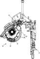
请参阅图1所示的一种圆锯机10,主要包含有一工作台11、一枢转地连接工作台11的锯臂12、一设于锯臂12的动力源13、一可旋转地枢设于锯臂12的一锯片容槽(图中未示)且连接动力源13的锯片14,以及一覆盖锯片14的护盖装置15,其中,护盖装置15具有一上护盖16及一下护盖17,上护盖16枢设于锯臂12,可受锯臂12的带动相对锯片14与锯臂12枢转,下护盖17则是枢设于锯臂12的底部,并具有一缺口(图中未示)供锯片14穿出。由此,当锯臂12朝工作台11枢转时,锯臂12会带动上护盖16相对于锯臂12朝远离锯片14外露部分的方向枢转,锯片14将会外露,亦可穿经下护盖17的缺口以锯切工件。Please refer to a
由于下护盖17并未具有定位结构而是处于可任意枢转的状态,若操作者在圆锯机10未使用时不慎碰触到下护盖17,可能迫使下护盖17朝锯片14方向枢转而导致锯片14从下护盖17的缺口穿出,如此将很容易产生操作者的手部被锯片14割伤的意外。Since the lower protective cover 17 does not have a positioning structure but is in a state that can pivot arbitrarily, if the operator accidentally touches the lower protective cover 17 when the
发明内容Contents of the invention
本发明的主要目的在于提供一种圆锯机的锯片护盖装置,其可避免发生手部不慎被锯片割伤的意外。The main purpose of the present invention is to provide a saw blade guard device for a circular saw machine, which can avoid the accident that the hand is accidentally cut by the saw blade.
为了达成上述目的,本发明的锯片护盖装置包含有一上护盖及一下护盖,其中的上护盖于一第一位置及一第二位置之间枢转地连接该圆锯机的一锯臂,该上护盖位于该第一位置时覆盖住该圆锯机的一锯片,该上护盖位于该第二位置时则是未覆盖住该锯片,另外,该上护盖的底端具有一第一定位部;该下护盖以其一端枢转地连接该锯臂而覆盖该锯片的底缘,并以其另一端伸入该上护盖内,该下护盖具有一第二定位部及一供该锯片穿出的缺口,该第一定位部可分离地与该下护盖的第二定位部接合。In order to achieve the above object, the saw blade cover device of the present invention includes an upper cover and a lower cover, wherein the upper cover is pivotally connected to a side of the circular saw between a first position and a second position. The saw arm, the upper cover covers a saw blade of the circular saw machine when the upper cover is in the first position, and does not cover the saw blade when the upper cover is in the second position. In addition, the upper cover The bottom end has a first positioning portion; the lower cover is pivotally connected to the saw arm at one end to cover the bottom edge of the saw blade, and extends into the upper cover with the other end. The lower cover has A second positioning portion and a notch for the saw blade to pass through. The first positioning portion is detachably engaged with the second positioning portion of the lower protective cover.
当未使用该圆锯机时,该上护盖的第一定位部与该下护盖的第二定位部之间是保持在接合的状态,若操作者的手部不慎碰触到该下护盖,该下护盖并不会产生枢转,该锯片护盖装置可完全地包覆该锯片,如此便能避免该锯片从该下护盖的缺口穿出而对操作者的手部造成割伤的意外。When the circular saw machine is not in use, the first positioning portion of the upper cover and the second positioning portion of the lower cover are kept in an engaged state. If the operator’s hand accidentally touches the lower Cover, the lower cover does not pivot, and the saw blade cover device can completely cover the saw blade, so as to prevent the saw blade from passing through the gap of the lower cover and causing serious damage to the operator. Accidents that cause cuts to the hands.
附图说明Description of drawings
为了详细说明本发明的结构、特征及功效所在,以下列举一较佳实施例并配合下列附图说明如后,其中:In order to describe in detail the structure, features and effects of the present invention, a preferred embodiment is listed below and described in conjunction with the following drawings as follows, wherein:
图1为现有锯片护盖装置安装于圆锯机的立体图。FIG. 1 is a perspective view of a conventional saw blade guard device installed on a circular saw machine.
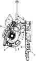
图2为本发明一较佳实施例安装于圆锯机的侧视图。Fig. 2 is a side view of a preferred embodiment of the present invention installed on a circular saw machine.
图3为图2的局部放大图,主要显示上护盖及下护盖之间的结合状态。FIG. 3 is a partially enlarged view of FIG. 2 , mainly showing the bonding state between the upper cover and the lower cover.
图4为图2的局部底视图,主要显示下护盖与锯片之间的关是。Fig. 4 is a partial bottom view of Fig. 2, mainly showing the relationship between the lower cover and the saw blade.
图5类同于图2,主要显示上护盖位于第二位置的状态。FIG. 5 is similar to FIG. 2 and mainly shows the state where the upper cover is in the second position.
图6类同于图3,主要显示本发明一较佳实施例的另一实施态样。FIG. 6 is similar to FIG. 3 and mainly shows another implementation aspect of a preferred embodiment of the present invention.
具体实施方式Detailed ways
请参阅图2,为应用本发明一较佳实施例的锯片护盖装置25的圆锯机20,图中所显示的圆锯机20包含有一用以置放工件的工作台21、一枢转地连接工作台21的锯臂22、一设于锯臂22的动力源23,以及一可旋转地容设于锯臂22的一锯片容槽中(图中未示)且连接动力源23的锯片24,由此,当锯片24受动力源23的驱动而旋转时,可再配合锯臂22相对工作台21的枢转而朝工作台21靠近,用以锯切置放于工作台21的工件。本发明的锯片护盖装置25包含有一上护盖26及一下护盖27。Referring to Fig. 2, it is a circular saw machine 20 using a saw
上护盖26枢转地连接锯臂22,并可受锯臂22的带动而于一第一位置P1及一第二位置P2之间枢转,当上护盖26位于第一位置P1时,如图2所示,上护盖26将覆盖锯片24的前缘,使锯片24的锯齿242不外露;当上护盖26位于第二位置P2时,如图5所示,上护盖26将不会覆盖锯片24的前缘而使锯片24的锯齿242外露。另外,上护盖26的底端的两相对侧分别具有一凹槽,该二凹槽形成一第一定位部262,如图3所示。The
下护盖27以其一端枢转地连接锯臂22而覆盖锯片24的底缘,并以其另一端伸入上护盖26内。下护盖27的底缘具有一供锯片24穿出的缺口272,如图4所示,下护盖27的两相对侧具有一凸部,该二凸部形成一第二定位部274。当锯臂22朝工作台21向下枢转时,上护盖26受锯臂22的带动而相对于锯臂朝远离锯片24外露部分的方向枢转至第二位置P2,迫使上护盖26的第一定位部262与下护盖27的第二定位部274互相分离,锯片24将会显露于外,如图5所示,下护盖27则会受到工件的推顶而产生枢转,此时的锯片24可以部分穿经下护盖27的缺口272以锯切工件。当完成工件的锯切作业而将锯臂22向上枢转时,下护盖27会由本身的重量(亦可设置回位弹簧,作为回位的装置)枢转至原本的位置,上护盖26则是同样受到锯臂22的带动朝锯片24外露部分的方向枢转至第一位置P1,使上护盖26的第一定位部262与下护盖27的第二定位部274相互接合,如图2所示,此时的下护盖27便完成定位,即使之后受到不当外力作用,下护盖27也不会产生枢转,如此当不进行切削作业时,锯片护盖装置25便能有效包覆锯片,避免操作者因锯片24外露而不小心所造成的伤害。The lower
另一方面,本发明的结构可有不同的变化,如图6所示,上护盖26的第一定位部262由该二凸部所构成,下护盖27的第二定位部274则由该二凹槽所构成,同样可让上护盖26及下护盖27在圆锯机10未使用时互相接合,以达到本发明的目的。On the other hand, the structure of the present invention can have different changes. As shown in FIG. The formation of the two grooves also allows the
本发明于前揭实施例中所揭露的构成元件,仅为举例说明,并非用来限制本案的范围,其它等效元件的替代或变化,亦应为本案的权利要求范围所涵盖。The constituent elements disclosed in the foregoing embodiments of the present invention are for illustration only and are not intended to limit the scope of the present application. Substitution or changes of other equivalent elements should also be covered by the claims of the present application.
Claims (4)
Translated fromChinesePriority Applications (1)
| Application Number | Priority Date | Filing Date | Title |
|---|---|---|---|
| CN201110006318.7ACN102581381B (en) | 2011-01-05 | 2011-01-05 | Saw blade protecting cover device of circular sawing machine |
Applications Claiming Priority (1)
| Application Number | Priority Date | Filing Date | Title |
|---|---|---|---|
| CN201110006318.7ACN102581381B (en) | 2011-01-05 | 2011-01-05 | Saw blade protecting cover device of circular sawing machine |
Publications (2)
| Publication Number | Publication Date |
|---|---|
| CN102581381Atrue CN102581381A (en) | 2012-07-18 |
| CN102581381B CN102581381B (en) | 2015-03-04 |
Family
ID=46470920
Family Applications (1)
| Application Number | Title | Priority Date | Filing Date |
|---|---|---|---|
| CN201110006318.7AExpired - Fee RelatedCN102581381B (en) | 2011-01-05 | 2011-01-05 | Saw blade protecting cover device of circular sawing machine |
Country Status (1)
| Country | Link |
|---|---|
| CN (1) | CN102581381B (en) |
Citations (6)
| Publication number | Priority date | Publication date | Assignee | Title |
|---|---|---|---|---|
| US1481569A (en)* | 1921-04-11 | 1924-01-22 | Tannewitz Works | Trimming saw |
| US4028975A (en)* | 1976-02-03 | 1977-06-14 | Ralph S. Rosen | Blade guard lift for power saw |
| US5184534A (en)* | 1990-11-16 | 1993-02-09 | Samsung Electronics Co., Ltd. | Operation safety device for a portable power tool |
| CN1943941A (en)* | 2005-10-07 | 2007-04-11 | 百得有限公司 | Saw |
| CN101767225A (en)* | 2010-03-16 | 2010-07-07 | 江苏金飞达电动工具有限公司 | Guard hood for combined saw |
| CN101875137A (en)* | 2009-04-28 | 2010-11-03 | 罗伯特·博世工具公司 | The security system of combination table-miter saw |
- 2011
- 2011-01-05CNCN201110006318.7Apatent/CN102581381B/ennot_activeExpired - Fee Related
Patent Citations (6)
| Publication number | Priority date | Publication date | Assignee | Title |
|---|---|---|---|---|
| US1481569A (en)* | 1921-04-11 | 1924-01-22 | Tannewitz Works | Trimming saw |
| US4028975A (en)* | 1976-02-03 | 1977-06-14 | Ralph S. Rosen | Blade guard lift for power saw |
| US5184534A (en)* | 1990-11-16 | 1993-02-09 | Samsung Electronics Co., Ltd. | Operation safety device for a portable power tool |
| CN1943941A (en)* | 2005-10-07 | 2007-04-11 | 百得有限公司 | Saw |
| CN101875137A (en)* | 2009-04-28 | 2010-11-03 | 罗伯特·博世工具公司 | The security system of combination table-miter saw |
| CN101767225A (en)* | 2010-03-16 | 2010-07-07 | 江苏金飞达电动工具有限公司 | Guard hood for combined saw |
Also Published As
| Publication number | Publication date |
|---|---|
| CN102581381B (en) | 2015-03-04 |
Similar Documents
| Publication | Publication Date | Title |
|---|---|---|
| CN103128640B (en) | Cutting machine | |
| CN108907338B (en) | Electric circular saw | |
| GB2482566A (en) | Shield for Guide Slot of Saw Blade in Table Saw | |
| TWI647039B (en) | Power equipment with quick release anti-kickback device | |
| CN204525393U (en) | Portable cutter | |
| JP5889740B2 (en) | Cutting tool | |
| JP6926440B2 (en) | Portable cutting machine | |
| CA2887644A1 (en) | Hand cutter with blade guard | |
| US20150343662A1 (en) | Table saws having integrated control systems | |
| CN103302353B (en) | Cutting device | |
| CN102581381B (en) | Saw blade protecting cover device of circular sawing machine | |
| KR200464516Y1 (en) | Saw blade protection device for meat cutter | |
| TW200838665A (en) | Stopping structure for table saw | |
| US8215215B2 (en) | Protective cover structure of a desk sawing machine | |
| CN205852398U (en) | Cutting machine without dead angle | |
| JP2017213647A (en) | Cutting machine | |
| US9446536B2 (en) | Miter saw rear guard | |
| CN201030588Y (en) | Stop structure for bench saw | |
| CN102310230A (en) | Saw blade protection mechanism of table saw machine | |
| EP2995408A1 (en) | Power circular saw | |
| CN106270756B (en) | Compound saw | |
| JP3153798U (en) | Electric circular saw chip dust prevention cover | |
| TWI483824B (en) | Blade guard assembly for a table saw | |
| TWI501850B (en) | Blade guard assembly for tile cutter | |
| WO2010100521A1 (en) | Improved compound chop sawing machine |
Legal Events
| Date | Code | Title | Description |
|---|---|---|---|
| C06 | Publication | ||
| PB01 | Publication | ||
| C10 | Entry into substantive examination | ||
| SE01 | Entry into force of request for substantive examination | ||
| C14 | Grant of patent or utility model | ||
| GR01 | Patent grant | ||
| CF01 | Termination of patent right due to non-payment of annual fee | Granted publication date:20150304 Termination date:20200105 | |
| CF01 | Termination of patent right due to non-payment of annual fee |