CN102579081A - Methods and apparatus for ultrasound imaging - Google Patents
Methods and apparatus for ultrasound imagingDownload PDFInfo
- Publication number
- CN102579081A CN102579081ACN2012100313327ACN201210031332ACN102579081ACN 102579081 ACN102579081 ACN 102579081ACN 2012100313327 ACN2012100313327 ACN 2012100313327ACN 201210031332 ACN201210031332 ACN 201210031332ACN 102579081 ACN102579081 ACN 102579081A
- Authority
- CN
- China
- Prior art keywords
- gain
- doppler
- noise
- curve
- signal
- Prior art date
- Legal status (The legal status is an assumption and is not a legal conclusion. Google has not performed a legal analysis and makes no representation as to the accuracy of the status listed.)
- Granted
Links
- 238000000034methodMethods0.000titleclaimsabstractdescription29
- 238000012285ultrasound imagingMethods0.000titledescription5
- 238000001228spectrumMethods0.000claimsabstractdescription82
- 230000001629suppressionEffects0.000claimsdescription37
- 230000004044responseEffects0.000claimsdescription7
- 230000003584silencerEffects0.000claims6
- 230000005764inhibitory processEffects0.000claims2
- 230000008676importEffects0.000claims1
- 230000003595spectral effectEffects0.000abstractdescription33
- 238000002604ultrasonographyMethods0.000abstractdescription11
- 230000017531blood circulationEffects0.000abstractdescription10
- 230000006870functionEffects0.000description12
- 230000008569processEffects0.000description6
- 238000001914filtrationMethods0.000description4
- 238000005070samplingMethods0.000description4
- 239000008280bloodSubstances0.000description3
- 210000004369bloodAnatomy0.000description3
- 230000005540biological transmissionEffects0.000description2
- 210000004204blood vesselAnatomy0.000description2
- 239000002131composite materialSubstances0.000description2
- 230000008878couplingEffects0.000description2
- 238000010168coupling processMethods0.000description2
- 238000005859coupling reactionMethods0.000description2
- 239000000523sampleSubstances0.000description2
- 208000024172Cardiovascular diseaseDiseases0.000description1
- 238000004458analytical methodMethods0.000description1
- 238000004364calculation methodMethods0.000description1
- 230000008859changeEffects0.000description1
- 238000011217control strategyMethods0.000description1
- 238000003745diagnosisMethods0.000description1
- 230000000694effectsEffects0.000description1
- 210000003754fetusAnatomy0.000description1
- 210000002216heartAnatomy0.000description1
- 238000003384imaging methodMethods0.000description1
- 210000004185liverAnatomy0.000description1
- 230000004048modificationEffects0.000description1
- 238000012986modificationMethods0.000description1
- 210000000056organAnatomy0.000description1
- 238000004611spectroscopical analysisMethods0.000description1
- 238000010183spectrum analysisMethods0.000description1
Images


Classifications
- A—HUMAN NECESSITIES
- A61—MEDICAL OR VETERINARY SCIENCE; HYGIENE
- A61B—DIAGNOSIS; SURGERY; IDENTIFICATION
- A61B8/00—Diagnosis using ultrasonic, sonic or infrasonic waves
- A61B8/06—Measuring blood flow
- G—PHYSICS
- G01—MEASURING; TESTING
- G01S—RADIO DIRECTION-FINDING; RADIO NAVIGATION; DETERMINING DISTANCE OR VELOCITY BY USE OF RADIO WAVES; LOCATING OR PRESENCE-DETECTING BY USE OF THE REFLECTION OR RERADIATION OF RADIO WAVES; ANALOGOUS ARRANGEMENTS USING OTHER WAVES
- G01S15/00—Systems using the reflection or reradiation of acoustic waves, e.g. sonar systems
- G01S15/88—Sonar systems specially adapted for specific applications
- G01S15/89—Sonar systems specially adapted for specific applications for mapping or imaging
- G01S15/8906—Short-range imaging systems; Acoustic microscope systems using pulse-echo techniques
- G01S15/8979—Combined Doppler and pulse-echo imaging systems
- G—PHYSICS
- G01—MEASURING; TESTING
- G01S—RADIO DIRECTION-FINDING; RADIO NAVIGATION; DETERMINING DISTANCE OR VELOCITY BY USE OF RADIO WAVES; LOCATING OR PRESENCE-DETECTING BY USE OF THE REFLECTION OR RERADIATION OF RADIO WAVES; ANALOGOUS ARRANGEMENTS USING OTHER WAVES
- G01S7/00—Details of systems according to groups G01S13/00, G01S15/00, G01S17/00
- G01S7/52—Details of systems according to groups G01S13/00, G01S15/00, G01S17/00 of systems according to group G01S15/00
- G01S7/52017—Details of systems according to groups G01S13/00, G01S15/00, G01S17/00 of systems according to group G01S15/00 particularly adapted to short-range imaging
- G01S7/52023—Details of receivers
- G01S7/52033—Gain control of receivers
- G—PHYSICS
- G01—MEASURING; TESTING
- G01S—RADIO DIRECTION-FINDING; RADIO NAVIGATION; DETERMINING DISTANCE OR VELOCITY BY USE OF RADIO WAVES; LOCATING OR PRESENCE-DETECTING BY USE OF THE REFLECTION OR RERADIATION OF RADIO WAVES; ANALOGOUS ARRANGEMENTS USING OTHER WAVES
- G01S7/00—Details of systems according to groups G01S13/00, G01S15/00, G01S17/00
- G01S7/52—Details of systems according to groups G01S13/00, G01S15/00, G01S17/00 of systems according to group G01S15/00
- G01S7/52017—Details of systems according to groups G01S13/00, G01S15/00, G01S17/00 of systems according to group G01S15/00 particularly adapted to short-range imaging
- G01S7/52077—Details of systems according to groups G01S13/00, G01S15/00, G01S17/00 of systems according to group G01S15/00 particularly adapted to short-range imaging with means for elimination of unwanted signals, e.g. noise or interference
Landscapes
- Engineering & Computer Science (AREA)
- Physics & Mathematics (AREA)
- Radar, Positioning & Navigation (AREA)
- Remote Sensing (AREA)
- Health & Medical Sciences (AREA)
- Computer Networks & Wireless Communication (AREA)
- General Physics & Mathematics (AREA)
- Life Sciences & Earth Sciences (AREA)
- Acoustics & Sound (AREA)
- Radiology & Medical Imaging (AREA)
- Molecular Biology (AREA)
- Pathology (AREA)
- Biophysics (AREA)
- Biomedical Technology (AREA)
- Heart & Thoracic Surgery (AREA)
- Medical Informatics (AREA)
- Nuclear Medicine, Radiotherapy & Molecular Imaging (AREA)
- Surgery (AREA)
- Animal Behavior & Ethology (AREA)
- General Health & Medical Sciences (AREA)
- Public Health (AREA)
- Veterinary Medicine (AREA)
- Hematology (AREA)
- Ultra Sonic Daignosis Equipment (AREA)
Abstract
Translated fromChinese
Description
Translated fromChinese本申请是申请日为2008年10月15日、申请号为200880114045.4(国际申请号为PCT/JP2008/069080)、发明名称为“用于超声波成像的方法和装置”的国际申请的分案申请。This application is a divisional application of an international application with an application date of October 15, 2008, application number 200880114045.4 (international application number PCT/JP2008/069080), and an invention title of "Method and Device for Ultrasonic Imaging".
技术领域technical field
本发明概括地涉及超声波成像的领域。更具体地,本发明的实施例涉及用于自动调节增益以及抑制用于测量流速的多普勒信号中显现的噪声的方法和系统。The present invention relates generally to the field of ultrasound imaging. More specifically, embodiments of the invention relate to methods and systems for automatically adjusting gain and suppressing noise manifested in Doppler signals used to measure flow velocity.
背景技术Background technique
超声波用于使心脏、肝脏、胎儿以及血管等各种器官成像。对于心血管病的诊断,多普勒频谱通常用于测量血流速度。脉冲多普勒技术通常由于其固有的空间采样能力而被使用,与不具有空间辨别能力并且沿着超声波束对所有信号进行采样的连续波(CW)多普勒相比,脉冲多普勒技术允许对血管中的速度进行采样。由于CW多普勒不受脉冲重复频率(PRF)极限(尼奎斯特采样理论)的限制,因此CW多普勒尤其用于期望测量高的血流速度时。由于执行诸如FFT(快速傅里叶变换)等的分析时要对信号采样,在最大速度上CW多普勒仍然受到限制。Ultrasound is used to image various organs such as the heart, liver, fetus, and blood vessels. For the diagnosis of cardiovascular disease, Doppler spectroscopy is commonly used to measure blood flow velocity. Pulsed Doppler techniques are often used due to their inherent spatial sampling capabilities, compared to continuous wave (CW) Doppler which is not spatially discriminative and samples all signals along the ultrasound beam. Allows sampling of velocities in blood vessels. CW Doppler is especially used when it is desired to measure high blood flow velocities since it is not limited by the pulse repetition frequency (PRF) limit (Nyquist sampling theory). CW Doppler is still limited in maximum speed due to the sampling of the signal when performing analysis such as FFT (Fast Fourier Transform).
多普勒系统典型地传输超声波并且随着在接收到的超声波信号中的频率的偏移(多普勒频移)来检测血流速度。利用基准信号对接收到的超声波进行解调,作为与传输频率处于相同频率的具有同相(I)和正交(Q)的复合信号。在低通滤波之后,阻止诸如二次谐波的高频成分,而仅通过基带信号。对基带信号施加壁滤波(即,高通滤波)以去除从固定组织中出现的杂波噪声并且缓慢地移动诸如血管壁的组织,导致了复合多普勒I-Q信号。将复合I-Q多普勒信号输入到诸如FFT分析仪的频谱分析仪,以获得表示血液速度的多普勒频谱。典型地,使用128点、256点以及512点的FFT。Doppler systems typically transmit ultrasound and detect blood flow velocity as a frequency shift (Doppler shift) in the received ultrasound signal. The received ultrasonic waves are demodulated using the reference signal as a composite signal with in-phase (I) and quadrature (Q) at the same frequency as the transmission frequency. After low-pass filtering, high-frequency components such as second harmonics are blocked, and only baseband signals are passed. Wall filtering (ie, high pass filtering) is applied to the baseband signal to remove clutter noise arising from fixed tissue and slowly moving tissue such as vessel walls, resulting in a complex Doppler I-Q signal. The composite I-Q Doppler signal is input to a spectrum analyzer such as an FFT analyzer to obtain a Doppler spectrum representing blood velocity. Typically, 128-point, 256-point, and 512-point FFTs are used.
由于血流的时间变化特性,如图12所示,多普勒频谱通常关于时间而显示。横轴是时间而纵轴是频率。频谱功率显示为如图12所示的亮度。如图3所示,频谱功率可以用给定时刻的频谱功率与频率进行比较来绘制。多普勒频谱可以显示部分地由超声波系统电子设备和其它源引起的噪声。图3示出了具有本底噪声(其表现为通过FFT而广泛分布的随机噪声)的多普勒频谱。如果多普勒流信号增益过低,则噪声可能掩盖真正的血流信号。相反,图1示出了具有过高的多普勒流信号增益(在该处,峰值多普勒频谱被削减)的多普勒频谱。Due to the time-varying nature of blood flow, the Doppler spectrum is usually displayed with respect to time, as shown in FIG. 12 . The horizontal axis is time and the vertical axis is frequency. Spectral power is displayed as brightness as shown in Figure 12. As shown in Figure 3, spectral power can be plotted by comparing spectral power at a given moment in time with frequency. The Doppler spectrum can reveal noise caused in part by ultrasound system electronics and other sources. Figure 3 shows the Doppler spectrum with a noise floor that appears as widely distributed random noise through the FFT. If the Doppler flow signal gain is too low, noise may mask the true blood flow signal. In contrast, FIG. 1 shows a Doppler spectrum with excessive Doppler flow signal gain (where the peak Doppler spectrum is clipped).
多普勒流信号增益确定了输入到FFT频谱分析仪的多普勒信号的振幅。多普勒频谱的输出通常被压缩在8位、12位、16位或其它分辨率的动态范围内。可以看出,输出到超声波系统的适当的多普勒流信号增益提高了多普勒频谱的SNR(信噪比),从而提高了显示时的图像质量。The Doppler flow signal gain determines the amplitude of the Doppler signal input to the FFT spectrum analyzer. The output of the Doppler spectrum is usually compressed within a dynamic range of 8-bit, 12-bit, 16-bit or other resolutions. It can be seen that an appropriate gain of the Doppler flow signal output to the ultrasound system improves the SNR (signal-to-noise ratio) of the Doppler spectrum, thereby improving the image quality when displayed.
现今的大多数超声波系统允许用户手动调节多普勒增益设置以获得最佳频谱。然而,用户在调节这些设置时所消耗的时间更适于花费在执行诊断上。因此存在克服这些问题的需求。Most ultrasound systems today allow the user to manually adjust the Doppler gain setting to obtain the optimum spectrum. However, the time the user spends adjusting these settings is better spent performing diagnostics. There is therefore a need to overcome these problems.
发明内容Contents of the invention
本发明人已经发现希望具有这样一种系统和方法:其在测量血流速度时检查通过超声波系统输出的多普勒频谱信号,以确定适当的多普勒增益并且抑制多普勒频谱中出现的噪声。检查多普勒频谱中出现的噪声并且将所述噪声用作最佳增益的标准。如果多普勒增益根据预定电平过高或过低,则调节总增益。The present inventors have found it desirable to have a system and method that examines the Doppler spectral signal output by an ultrasound system to determine the appropriate Doppler gain and suppress the noise. The presence of noise in the Doppler spectrum is checked and used as a criterion for optimum gain. If the Doppler gain is too high or too low according to a predetermined level, the overall gain is adjusted.
本发明的一个方案提供了用于在超声波成像期间自动控制来自多普勒信号处理器的增益的方法。根据本发明的该方案的方法包括:输入返回的超声波信号;对所述返回的超声波信号进行解调;对所述返回的超声波信号进行壁滤波,产生多普勒流信号;对所述多普勒流信号执行频谱分析,产生多普勒频谱;设置高电平信号阈值;设置低电平信号阈值;设置本底噪声电平阈值;根据所述多普勒流信号来检测峰值多普勒频谱电平和多普勒频谱最大本底噪声;如果所述峰值多普勒频谱振幅小于所述低电平信号阈值,则增加多普勒流信号增益,直到所述峰值多普勒频谱振幅等于所述高电平信号阈值或所述最大本底噪声等于所述本底噪声电平阈值;以及如果所述峰值多普勒频谱振幅大于所述高电平信号阈值,则减小所述多普勒流信号增益,直到所述峰值多普勒频谱振幅等于所述高电平信号阈值或所述最大本底噪声等于所述本底噪声电平阈值。One aspect of the invention provides a method for automatically controlling the gain from a Doppler signal processor during ultrasound imaging. The method according to the solution of the present invention includes: inputting the returned ultrasonic signal; demodulating the returned ultrasonic signal; performing wall filtering on the returned ultrasonic signal to generate a Doppler flow signal; Perform spectrum analysis on the Le flow signal to generate a Doppler spectrum; set the high-level signal threshold; set the low-level signal threshold; set the background noise level threshold; detect the peak Doppler spectrum according to the Doppler flow signal level and Doppler spectrum maximum noise floor; if the peak Doppler spectrum amplitude is less than the low level signal threshold, then increase the Doppler flow signal gain until the peak Doppler spectrum amplitude is equal to the a high-level signal threshold or said maximum noise floor is equal to said noise-floor level threshold; and if said peak Doppler spectral amplitude is greater than said high-level signal threshold, reducing said Doppler flow signal gain until the peak Doppler spectral amplitude equals the high level signal threshold or the maximum noise floor equals the noise floor level threshold.
本发明的另一方案提供了用于在超声波成像期间自动控制多普勒频谱处理器的增益的系统。根据本发明的该方案的系统包括:接收器,其被配置为接收返回的超声波信号并且具有输出端;多普勒信号处理器,其具有输出端和联结到接收器输出端的输入端,所述多普勒信号处理器被配置为对所述返回的超声波信号进行解调和壁滤波并且输出多普勒流信号;可变增益放大器,其具有联结到所述多普勒信号处理器输出端的输入端、增益控制信号输入端和输出端,所述可变增益放大器被配置为改变所述多普勒流信号的增益;频谱分析仪,其具有输出端和联结到所述可变增益放大器输出端的输入端,所述频谱分析仪被配置为将所述多普勒流信号变换为其对应的频谱;以及自动增益机,其联结到所述频谱分析仪输出端,所述自动增益机被配置为接收所述多普勒频谱并且检测峰值多普勒频谱振幅和最大本底噪声,其中,基于所述多普勒流信号频谱中存在的所述最大本底噪声以及预定的高信号电平阈值、低信号电平阈值和本底噪声信号电平阈值来计算增益控制信号并且将所述增益控制信号联结到所述可变增益放大器增益控制信号输入端,其中,如果所述峰值多普勒频谱振幅大于所述高电平信号阈值,或小于所述低电平信号阈值,则调节总增益以保持所述峰值多普勒频谱振幅大于所述低电平信号阈值并且小于所述高电平信号阈值。Another aspect of the invention provides a system for automatically controlling the gain of a Doppler spectral processor during ultrasound imaging. The system according to this aspect of the invention includes: a receiver configured to receive the returned ultrasonic signal and having an output; a Doppler signal processor having an output and an input coupled to the output of the receiver, the a Doppler signal processor configured to demodulate and wall filter the returned ultrasound signal and output a Doppler flow signal; a variable gain amplifier having an input coupled to the output of the Doppler signal processor terminal, a gain control signal input terminal and an output terminal, the variable gain amplifier is configured to change the gain of the Doppler flow signal; a spectrum analyzer has an output terminal and an output terminal coupled to the variable gain amplifier output terminal an input, the spectrum analyzer is configured to transform the Doppler stream signal into its corresponding spectrum; and an automatic gain machine, coupled to the spectrum analyzer output, the automatic gain machine is configured to receiving the Doppler spectrum and detecting a peak Doppler spectrum amplitude and a maximum noise floor, wherein based on the maximum noise floor present in the Doppler flow signal spectrum and a predetermined high signal level threshold, low signal level threshold and noise floor signal level threshold to calculate a gain control signal and couple the gain control signal to the variable gain amplifier gain control signal input, wherein if the peak Doppler spectral amplitude greater than the high-level signal threshold, or less than the low-level signal threshold, then adjust the overall gain to keep the peak Doppler spectrum amplitude greater than the low-level signal threshold and less than the high-level signal threshold .
本发明的另一方案提供了用于抑制多普勒频谱信号上出现的噪声的方法。根据本发明的该方案的方法包括:输入所述多普勒频谱信号;接收多普勒增益控制信号;使用对应于所述多普勒增益控制信号的噪声抑制增益曲线g(p);以及利用所述噪声抑制增益曲线g(p)来处理所述多普勒频谱振幅,其中,根据所述噪声抑制增益曲线的响应来调节所述多普勒频谱振幅的各个频率。Another aspect of the present invention provides a method for suppressing noise present on a Doppler spectral signal. The method according to this solution of the present invention includes: inputting the Doppler spectrum signal; receiving a Doppler gain control signal; using a noise suppression gain curve g(p) corresponding to the Doppler gain control signal; and using The noise suppression gain curve g(p) processes the Doppler spectral amplitude, wherein individual frequencies of the Doppler spectral amplitude are adjusted according to the response of the noise suppression gain curve.
本发明的另一方案提供了用于抑制多普勒频谱信号上出现的噪声的噪声抑制系统。根据本发明的该方案的系统包括:输入端,其被配置为接收经增益调节的多普勒频谱信号;增益控制信号输入端,其被配置为接收用于调节所述经增益调节的多普勒频谱信号的增益的增益控制信号,以生成噪声抑制增益曲线g(p);增益函数处理器,其被配置为利用所述噪声抑制增益曲线g(p)来处理所述经增益调节的多普勒流信号,其中,根据所述噪声抑制增益曲线g(p)的响应来调节所述多普勒频谱信号输入端的各个频谱成分的振幅;以及输出端,其被配置为输出经噪声抑制且经增益调节的多普勒流信号。Another aspect of the present invention provides a noise suppression system for suppressing noise present on a Doppler spectral signal. The system according to this solution of the present invention comprises: an input end configured to receive a gain-adjusted Doppler spectrum signal; a gain control signal input end configured to receive a Doppler spectrum signal for adjusting the gain-adjusted a gain control signal of the gain of the Le spectrum signal to generate a noise suppression gain curve g(p); a gain function processor configured to process the gain-adjusted multiple a Doppler flow signal, wherein the amplitude of each spectral component of the Doppler spectral signal input is adjusted according to the response of the noise suppression gain curve g(p); and an output configured to output a noise suppressed and Gain-adjusted Doppler flow signal.
在附图和下列描述中阐述了本发明的一个或多个实施例的细节。本发明的其它特征、目的和优点将通过描述和附图以及通过权利要求而显而易见。The details of one or more embodiments of the invention are set forth in the accompanying drawings and the description below. Other features, objects, and advantages of the invention will be apparent from the description and drawings, and from the claims.
附图说明Description of drawings
图1为示范性的高增益多普勒频谱图。FIG. 1 is an exemplary high-gain Doppler spectrogram.
图2为示范性的低增益多普勒频谱图。FIG. 2 is an exemplary low-gain Doppler spectrogram.
图3为具有本底噪声的示范性多普勒频谱图。FIG. 3 is an exemplary Doppler spectrogram with a noise floor.
图4为示范性的噪声抑制增益函数g(p)。FIG. 4 shows an exemplary noise suppression gain function g(p).
图5A为在噪声抑制之前的示范性多普勒频谱。FIG. 5A is an exemplary Doppler spectrum before noise suppression.
图5B为在噪声抑制之后的示范性多普勒频谱。FIG. 5B is an exemplary Doppler spectrum after noise suppression.
图6为具有自动多普勒增益控制系统和噪声抑制器的示范性多普勒频谱处理器。FIG. 6 is an exemplary Doppler spectrum processor with an automatic Doppler gain control system and a noise suppressor.
图7为描述自动多普勒增益控制方法的示范性流程图。FIG. 7 is an exemplary flowchart describing an automatic Doppler gain control method.
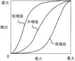
图8为示范性的多个噪声抑制增益曲线。FIG. 8 shows exemplary noise suppression gain curves.
图9为描述噪声抑制方法的示范性流程图。FIG. 9 is an exemplary flowchart describing a noise suppression method.
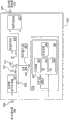
图10为具有自动多普勒增益控制和噪声抑制的示范性超声波成像系统。10 is an exemplary ultrasound imaging system with automatic Doppler gain control and noise suppression.
图11A为示范性增益函数处理器g(p)和g(p)发生器。11A is an exemplary gain function processor g(p) and g(p) generator.
图11B为具有发生器的示范性增益函数处理器g(p)。FIG. 11B is an exemplary gain function processor g(p) with a generator.
图12为关于时间的示范性多普勒频谱。Fig. 12 is an exemplary Doppler spectrum with respect to time.
具体实施方式Detailed ways
将结合附图来描述本发明的实施例,在全部附图中,相似的数字表示相似的元件。在对本发明的实施例进行详细地解释之前,应当理解的是,本发明不局限于其对在下列描述中提出的或在附图中图示的示例的细节的应用。本发明可以为其它实施例,且可以以各种应用并以各种方式来实践或实施。而且,应当理解的是,本文所使用的措辞和术语是为了描述的目的并且不应当视为限制。本文所使用的“包括(including)”、“包括(comprising)”或“具有”及其变化是指包括之后所罗列的项目及其等同物以及其它项目。术语“安装”、“连接”和“联结(coupled)”被广泛地使用并且包括直接和间接的安装、连接和联结。此外,“连接”和“联结”不限于物理或机械的连接或联结。Embodiments of the present invention will be described with reference to the drawings, wherein like numerals indicate like elements throughout. Before embodiments of the invention are explained in detail, it is to be understood that the invention is not limited in its application to the details of the examples set forth in the following description or illustrated in the drawings. The invention is capable of other embodiments and of being practiced or carried out in various applications and in various ways. Also, it is to be understood that the phraseology and terminology used herein are for the purpose of description and should not be regarded as limiting. As used herein, "including," "comprising," or "having" and variations thereof mean that the items listed thereafter and their equivalents as well as other items are included. The terms "mounted", "connected" and "coupled" are used broadly and include both direct and indirect mountings, connections and couplings. Furthermore, "connected" and "coupled" are not limited to physical or mechanical connections or couplings.
应当注意到的是,本发明不局限于所描述的或附图中隐含的任何特定的软件语言。本领域普通技术人员应当理解的是,各种可选软件语言可以用于实施本发明。还应当注意到的是,作为本领域内的通常惯例,图示并描述了一些部件和项目,好像它们是硬件元件一样。然而,本领域普通技术人员基于对详细说明书的阅读应当理解的是,在至少一个实施例中,可以以软件或硬件来实施方法和系统中的部件。It should be noted that the invention is not limited to any particular software language described or implied in the drawings. Those of ordinary skill in the art will appreciate that various alternative software languages can be used to implement the present invention. It should also be noted that, as is common practice in the art, some components and items are shown and described as if they were hardware elements. However, those of ordinary skill in the art should understand based on reading the detailed description that, in at least one embodiment, the methods and components in the system can be implemented in software or hardware.
图10示出了包括具有自动多普勒增益和噪声抑制系统的多普勒频谱处理器1010的超声波系统。图6示出了具有自动增益机619和噪声抑制器617的多普勒处理器1010。图7示出了描述自动多普勒增益方法的流程图。图9示出了描述噪声抑制方法的流程图。通过发送/接收开关1004,从由发送器1002驱动的超声波探测器1006发送超声波信号。接收器1008通过开关1004接收来自探测器1006的超声波信号并且对信号1009进行处理(步骤705)。Figure 10 shows an ultrasound system including a
接收器1008将经处理的信号1009输出到多普勒频谱处理器1010、彩色流处理器1012和B模式图像处理器1014。多普勒频谱处理器1010对信号1009进行处理,并且将多普勒频谱输出到扫描变换器1016。彩色流处理器1012对信号1009进行处理,并且将彩色流图像输出到扫描变换器1016。B模式图像处理器1014对信号1009进行处理,并且将B模式图像输出到扫描变换器1016。扫描变换器1016接收来自B模式图像、彩色流图像和多普勒频谱的一个或多个信号,并且将这些图像变换为经扫描变换的图像以输出到显示监视器1018。
将经处理的信号1009联结到多普勒信号处理器611以在时域中计算多普勒流信号612(步骤710)。将多普勒流信号612联结到可变增益放大器(VGA)613以调节多普勒信号的增益。将经增益调节的多普勒信号614联结到将时域多普勒信号变换为其频谱频率成分的频谱分析仪615(步骤715)。将频率成分或频谱616联结到噪声抑制器617和自动增益机619。噪声抑制器617具有可以为如图4所示的曲线g(p)的输入-输出关系。如图11A和图11B所示,噪声抑制器617可以被实施为具有输入-输出关系g(p)1102或1110的查阅表(LUT)、或者计算器1110或组合,以及也可以为LUT或计算器的增益曲线发生器1104。对于LUT与计算器相结合作为发生器1104的情形,可以将噪声抑制曲线存储在LUT中,并且计算器接收抑制曲线并且生成对应于增益控制信号642的曲线。The processed
对于LUT单独用作发生器1104的情形,将多条噪声抑制曲线存储在LUT中并且对应于增益控制信号642来选择噪声抑制曲线。可选择地,单独作为发生器1104的计算器可以生成对应于多普勒增益曲线的噪声抑制曲线。然后发生器1104将曲线传递到增益函数处理器1102,增益函数处理器1102可以为LUT并且将噪声抑制曲线g(p)应用于多普勒频谱616。可选择地,如图11B所示,增益函数g(p)处理器1102和噪声抑制曲线发生器1104可以被实施为一个装置1110。可以使用具有多普勒频谱616输入和增益控制信号642输出的LUT。可选择地,计算器1110可以用于生成噪声抑制曲线以及将增益函数g(p)应用于多普勒频谱616。For the case where a LUT alone is used as the
噪声抑制器617抑制多普勒频谱616上出现的噪声。噪声抑制器617输出经抑制噪声的多普勒频谱(输出625)。自动增益机619包括低通滤波器626和信号阈值处理器629。低通滤波器626对由频谱分析仪615输出的频谱频率成分616进行滤波,产生了经平滑的频谱627,并且输出到信号阈值处理器629。还将原始多普勒频谱616联结到信号阈值处理器629(步骤720)。
信号阈值处理器629包括用于检测经平滑的频谱627的电平的高电平阈值631、低电平阈值633和本底噪声电平阈值635,以及用于检测频率成分的频率点计数器(frequency bin counter)637。同样地,信号阈值处理器629包括用于检测原始多普勒频谱616的电平的高电平阈值631、低电平阈值633和本底噪声电平阈值635,以及用于检测频率成分的频率点计数器637(步骤725)。图3示出了高电平阈值631、低电平阈值633和本底噪声电平阈值635对比最大频谱振幅电平的示范性的经平滑的多普勒频谱。最大频谱振幅电平典型地为255(8位)、511(9位)、1023(10位),或其它电平。高信号电平阈值631可以为例如255、250、225或200,最大为255。低信号电平阈值633例如可以为128,最大频谱电平为255;本底噪声电平阈值635可以为例如16,最大频谱电平为255。The
通过由频谱分析仪615将峰值多普勒频谱输出616与高信号电平阈值613和低信号电平阈值633相比较,自动增益机619优化多普勒流信号增益。频率点计数器637对振幅大于高信号电平阈值631的多个连续多普勒频谱频率616进行计数。频率点计数器637还对振幅大于低信号电平阈值633的多个连续多普勒频谱频率进行计数。频率点计数器637还检测本底噪声301(即多普勒频谱中的平坦部分)的最大电平。The
图1示出了多普勒频谱101,其显示被削减的(103)峰值多普勒频谱627。削减出现在多普勒频谱振幅超过最大频谱电平时。削减指示多普勒增益过高。在本发明中,如果振幅大于高信号电平阈值631的连续频谱频率(或频率点)的数量大于预定数目,例如10,则认为多普勒增益613过高。FIG. 1 shows a
图2示出了显示指示多普勒增益过低的低(201)峰值多普勒频谱627或616振幅(或功率)的多普勒频谱。在本发明中,如果振幅大于低信号电平阈值633的连续频谱频率(或频率点)的数量小于预定数目,例如10,则认为可变增益放大器613的增益(多普勒增益)过低。Figure 2 shows a Doppler spectrum showing a low (201)
除原始(即,单个)多普勒频谱616以外,经平滑(低通滤波)的多普勒频谱627还可以以较少的预设(计数)数目和/或较低的高信号电平来使用。In addition to the raw (i.e., single)
由于大多数的电噪声是随机的,因此自动增益机619检测可以横跨整个频率范围展开的本底噪声。当计算多普勒频谱时,噪声由于其宽带特性而横跨整个频率范围展开。如果血流速度小于最大速度或多普勒频谱带宽小于PRF,则容易检测到噪声。图3示出了连同多普勒频谱一起的最大本底噪声301和高信号电平阈值631与低信号电平阈值633之间的静区303。如图3所示,可以容易地识别仅由本底噪声构成的频带(低电平纹波),并且在该频率范围中确定本底噪声的最大电平301。例如,对于除基线(0频率)附近以外的全部频谱频率成分,可以计算预定数目(例如10个)的连续频率成分(点)的平均振幅,因为在该区域中由于壁滤波器效应而不存在噪声。在图3中可以看出,对于血流,本底噪声区域的平均振幅将比频谱频率成分的平均振幅小得多。因此,与血流面积进行比较来确定本底噪声面积。获得了最小平均振幅并且用预定因子乘最小平均振幅以估算最大本底噪声。由于血液速度在心脏收缩期间为高而在心脏舒张期间为低,因此血流速度随时间而变化。因此,在心脏舒张期间,因为血流低且高频不存在(即仅显示本底噪声),所以本底噪声通常出现在高频区域中。这可以进一步用于识别本底噪声。Since most electrical noise is random,
如果峰值多普勒频谱627或616小于低信号电平阈值633,则自动增益机619生成输出到可变增益放大器613的增益控制信号630(步骤730)。增益控制信号630通过自动/手动多普勒增益模式开关639而联结到可变增益放大器613。开关639通过在导出的增益控制信号630与用户调节的手动增益控制信号641之间切换而允许用户在自动增益控制与用户增益控制之间进行选择。增益控制信号630可以从多个控制策略中导出并且对应于提高峰值多普勒频谱所需的校正量,即,振幅超过高电平阈值631的连续频谱频率627的数目等于预定数目或预定数目减去小的预设数目,直到实现校正增益。如果本底噪声301存在并且与峰值多普勒频谱627成比例地升至本底噪声电平阈值635以上,则调节增益控制信号630,减小多普勒增益使得本底噪声等于或小于本底噪声电平阈值635(步骤735)。If the
如果振幅超过高电平阈值631的连续多普勒频谱频率(即频率点)的数目大于预定数目,则检测到高增益并且自动增益机619生成输出到可变增益放大器613的增益控制信号630(步骤740)。增益控制信号630对应于减小峰值多普勒频谱所需的校正量,即,振幅超过高电平阈值631的连续频谱频率627或616的数目等于预定数目或预定数目减去预设数目,直到实现校正增益。如果本底噪声301存在并且大于本底噪声电平阈值635,则调节增益控制信号630,减小多普勒增益使得本底噪声等于或小于本底噪声电平阈值635(步骤745)。If the number of consecutive Doppler spectral frequencies (i.e., frequency bins) whose amplitudes exceed the
如果峰值多普勒频谱627或616小于或等于高信号电平阈值631情况(即,如果振幅超过高电平的连续频谱频率的数目超过预定数目),并且如果最大本底噪声301大于本底噪声电平阈值635,则调节增益控制信号630。减小多普勒增益,使得最大本底噪声等于或小于本底噪声电平阈值635。If the
噪声抑制器617抑制多普勒信号616上出现的噪声。图9示出了描述噪声抑制方法的流程图。由于本底噪声随着增益(多普勒增益)而变化,因此噪声抑制器617取决于增益控制信号642(步骤905、910)。如果多普勒增益增加,则噪声抑制器617接收增益控制信号642并且从增益曲线发生器1104或1110中存储或生成的多条增益曲线中选择噪声抑制增益曲线(步骤915)。
图8示出了对于低增益、中增益和高增益情况下在发生器1104或1110中存储或生成的三条噪声抑制增益曲线的示例。在增益曲线发生器1104或1110中存储或生成的抑制增益曲线与增益设置一致。如图8所示,如果增益控制信号所指示的多普勒增益为低,则选择或生成“低增益”的噪声抑制曲线。如果多普勒增益为中,则选择或生成“中增益”的噪声抑制曲线。如果增益为高,则选择或生成“高增益”的噪声抑制曲线。将选择出的噪声抑制增益曲线作为增益函数g(p)加载到增益函数处理器1102或1110中(步骤920)。在另一示例中,如果多普勒增益控制信号642设置为1,则选择或生成第1抑制曲线。如果多普勒增益控制信号642设置为2,则选择或生成第2抑制曲线。同样地,如果多普勒增益控制信号为N,则选择或生成第N抑制曲线。加载选择出的噪声抑制增益曲线,作为增益函数g(p)1102或1110(步骤920)。如图11A和图11B所示,噪声抑制器617可以包括单个计算器、具有LUT的计算器、或多个LUT,并且使用增益控制信号642。Figure 8 shows an example of three noise suppression gain curves stored or generated in
噪声抑制器617接收多普勒频谱616,并且利用响应g(p)1102或1110来变换各个频谱幅度p。增益函数g(p)1102或1110为来自增益曲线发生器1104或1110的增益曲线。图4示出了作为曲线的增益函数g(p)。The
图5A示出了具有噪声的多普勒频谱。图5B示出了噪声抑制器617的结果(步骤925)。噪声抑制器617应用了降低本底噪声的噪声抑制曲线技术。Figure 5A shows a Doppler spectrum with noise. Figure 5B shows the results of the noise suppressor 617 (step 925).
已经描述了本发明的一个或多个实施例。然而,应当理解的是,可以在不背离本发明的精神和范围的情况下进行各种改进。本发明中信号的处理顺序可以变化。本发明中系统处理器的顺序也可以变化。每个处理器还可以用其它处理器来替换。方法步骤的顺序可以变化。方法可以进行改进。因此,其它实施例在以下权利要求的范围内。One or more embodiments of the invention have been described. However, it should be understood that various modifications may be made without departing from the spirit and scope of the invention. The order in which signals are processed in the present invention may vary. The order of the system processors in the present invention can also be varied. Each processor can also be replaced with other processors. The order of method steps may vary. method can be improved. Accordingly, other embodiments are within the scope of the following claims.
Claims (9)
Applications Claiming Priority (2)
| Application Number | Priority Date | Filing Date | Title |
|---|---|---|---|
| US11/926,228US20090112096A1 (en) | 2007-10-29 | 2007-10-29 | Methods and apparatus for ultrasound imaging |
| US11/926,228 | 2007-10-29 |
Related Parent Applications (1)
| Application Number | Title | Priority Date | Filing Date |
|---|---|---|---|
| CN200880114045.4ADivisionCN101842054B (en) | 2007-10-29 | 2008-10-15 | Method and apparatus for ultrasound imaging |
Publications (2)
| Publication Number | Publication Date |
|---|---|
| CN102579081Atrue CN102579081A (en) | 2012-07-18 |
| CN102579081B CN102579081B (en) | 2015-01-07 |
Family
ID=40583745
Family Applications (2)
| Application Number | Title | Priority Date | Filing Date |
|---|---|---|---|
| CN201210031332.7AExpired - Fee RelatedCN102579081B (en) | 2007-10-29 | 2008-10-15 | Methods and apparatus for ultrasound imaging |
| CN200880114045.4AExpired - Fee RelatedCN101842054B (en) | 2007-10-29 | 2008-10-15 | Method and apparatus for ultrasound imaging |
Family Applications After (1)
| Application Number | Title | Priority Date | Filing Date |
|---|---|---|---|
| CN200880114045.4AExpired - Fee RelatedCN101842054B (en) | 2007-10-29 | 2008-10-15 | Method and apparatus for ultrasound imaging |
Country Status (5)
| Country | Link |
|---|---|
| US (1) | US20090112096A1 (en) |
| EP (1) | EP2205159B1 (en) |
| JP (1) | JP5324589B2 (en) |
| CN (2) | CN102579081B (en) |
| WO (1) | WO2009057486A1 (en) |
Cited By (1)
| Publication number | Priority date | Publication date | Assignee | Title |
|---|---|---|---|---|
| CN108420457A (en)* | 2017-11-27 | 2018-08-21 | 苏州掌声医疗科技有限公司 | A kind of device of Dopplcr ultrasound blood gain-adjusted |
Families Citing this family (20)
| Publication number | Priority date | Publication date | Assignee | Title |
|---|---|---|---|---|
| WO2010123573A1 (en) | 2009-04-23 | 2010-10-28 | Maxlinear, Inc. | Channel-sensitive power control |
| CN101879076B (en)* | 2009-05-08 | 2013-09-04 | 深圳迈瑞生物医疗电子股份有限公司 | Method and device for automatically optimizing Doppler ultrasonic imaging |
| JP2010274068A (en)* | 2009-06-01 | 2010-12-09 | Toshiba Corp | Ultrasonic diagnostic apparatus and image display method in ultrasonic diagnostic apparatus |
| JP5433348B2 (en)* | 2009-08-26 | 2014-03-05 | 株式会社東芝 | Ultrasonic diagnostic equipment |
| US8430817B1 (en) | 2009-10-15 | 2013-04-30 | Masimo Corporation | System for determining confidence in respiratory rate measurements |
| US9848800B1 (en) | 2009-10-16 | 2017-12-26 | Masimo Corporation | Respiratory pause detector |
| US9307928B1 (en) | 2010-03-30 | 2016-04-12 | Masimo Corporation | Plethysmographic respiration processor |
| JP5570877B2 (en) | 2010-06-04 | 2014-08-13 | 株式会社東芝 | Ultrasonic diagnostic equipment |
| US8989311B2 (en)* | 2010-09-22 | 2015-03-24 | Qualcomm Incorporated | Methods and systems for improved channel estimation in multi-carrier systems |
| KR101158640B1 (en)* | 2010-11-03 | 2012-06-26 | 삼성메디슨 주식회사 | Ultrasound system and method for controlling gain |
| WO2014063005A1 (en) | 2012-10-18 | 2014-04-24 | Washington University | Transcranialphotoacoustic/thermoacoustic tomography brain imaging informed by adjunct image data |
| US10441181B1 (en) | 2013-03-13 | 2019-10-15 | Masimo Corporation | Acoustic pulse and respiration monitoring system |
| CN103532529B (en)* | 2013-10-28 | 2015-12-09 | 中国医学科学院生物医学工程研究所 | The electromagnetic pulse noise suppressing method detected for magnetoacoustic signals and device thereof |
| JP6591242B2 (en)* | 2015-09-14 | 2019-10-16 | キヤノンメディカルシステムズ株式会社 | Ultrasonic diagnostic apparatus and signal processing apparatus |
| US10852427B2 (en)* | 2017-06-30 | 2020-12-01 | Gopro, Inc. | Ultrasonic ranging state management for unmanned aerial vehicles |
| CN109787716B (en)* | 2018-12-19 | 2020-12-29 | 惠科股份有限公司 | Data transmission method and device |
| CN109951408B (en)* | 2019-04-16 | 2021-11-09 | 苏州浪潮智能科技有限公司 | DPD output correction method, system and device |
| US12318637B2 (en)* | 2019-05-31 | 2025-06-03 | Sunnybrook Research Institute | Systems and methods for reducing thermal skull-induced aberrations during transcranial ultrasound therapeutic procedures |
| CN112120734B (en)* | 2020-10-20 | 2022-11-11 | 深圳开立生物医疗科技股份有限公司 | Doppler frequency spectrum generation method and device in blood flow direction and related equipment |
| US20230404520A1 (en)* | 2022-06-16 | 2023-12-21 | California Institute Of Technology | Methods and systems for photoacoustic computed tomography of blood flow |
Citations (4)
| Publication number | Priority date | Publication date | Assignee | Title |
|---|---|---|---|---|
| US6512854B1 (en)* | 1999-05-07 | 2003-01-28 | Koninklijke Philips Electronics N.V. | Adaptive control and signal enhancement of an ultrasound display |
| JP2004500915A (en)* | 2000-04-24 | 2004-01-15 | アキュソン コーポレーション | Medical ultrasound imaging system with adaptive multidimensional backend mapping |
| WO2006095287A1 (en)* | 2005-03-08 | 2006-09-14 | Koninklijke Philips Electronics, N.V. | Method and apparatus for automatic gain adjustment in spectral doppler |
| JP2007152111A (en)* | 2005-12-01 | 2007-06-21 | General Electric Co <Ge> | Method and apparatus for automatically regulating spectral doppler gain |
Family Cites Families (11)
| Publication number | Priority date | Publication date | Assignee | Title |
|---|---|---|---|---|
| US5935074A (en)* | 1997-10-06 | 1999-08-10 | General Electric Company | Method and apparatus for automatic tracing of Doppler time-velocity waveform envelope |
| US6296612B1 (en)* | 1999-07-09 | 2001-10-02 | General Electric Company | Method and apparatus for adaptive wall filtering in spectral Doppler ultrasound imaging |
| JP4117383B2 (en)* | 2000-03-22 | 2008-07-16 | ジーイー・メディカル・システムズ・グローバル・テクノロジー・カンパニー・エルエルシー | Ultrasound imaging device |
| US6398733B1 (en)* | 2000-04-24 | 2002-06-04 | Acuson Corporation | Medical ultrasonic imaging system with adaptive multi-dimensional back-end mapping |
| US6510339B2 (en)* | 2000-12-06 | 2003-01-21 | Cardiac Pacemakers, Inc. | ECG auto-gain control |
| GB0030449D0 (en)* | 2000-12-13 | 2001-01-24 | Deltex Guernsey Ltd | Improvements in or relating to doppler haemodynamic monitors |
| JP4008251B2 (en)* | 2002-02-01 | 2007-11-14 | ジーイー・メディカル・システムズ・グローバル・テクノロジー・カンパニー・エルエルシー | Doppler gain control device and ultrasonic imaging device |
| JP2003319940A (en)* | 2002-05-07 | 2003-11-11 | Aloka Co Ltd | Ultrasonic diagnostic device |
| US7374539B2 (en)* | 2003-09-02 | 2008-05-20 | University Of Utah Research Foundation | Method and apparatus for predicting material hypertension during pregnancy using coherence analysis of material and fetal blood velocity waveforms |
| US7513872B2 (en)* | 2004-10-18 | 2009-04-07 | Kabushiki Kaisha Toshiba | Ultrasonic doppler measuring apparatus and control method therefor |
| US8435180B2 (en)* | 2007-09-17 | 2013-05-07 | Siemens Medical Solutions Usa, Inc. | Gain optimization of volume images for medical diagnostic ultrasonic imaging |
- 2007
- 2007-10-29USUS11/926,228patent/US20090112096A1/ennot_activeAbandoned
- 2008
- 2008-10-15JPJP2010530679Apatent/JP5324589B2/ennot_activeExpired - Fee Related
- 2008-10-15WOPCT/JP2008/069080patent/WO2009057486A1/enactiveApplication Filing
- 2008-10-15EPEP08845439.2Apatent/EP2205159B1/ennot_activeNot-in-force
- 2008-10-15CNCN201210031332.7Apatent/CN102579081B/ennot_activeExpired - Fee Related
- 2008-10-15CNCN200880114045.4Apatent/CN101842054B/ennot_activeExpired - Fee Related
Patent Citations (4)
| Publication number | Priority date | Publication date | Assignee | Title |
|---|---|---|---|---|
| US6512854B1 (en)* | 1999-05-07 | 2003-01-28 | Koninklijke Philips Electronics N.V. | Adaptive control and signal enhancement of an ultrasound display |
| JP2004500915A (en)* | 2000-04-24 | 2004-01-15 | アキュソン コーポレーション | Medical ultrasound imaging system with adaptive multidimensional backend mapping |
| WO2006095287A1 (en)* | 2005-03-08 | 2006-09-14 | Koninklijke Philips Electronics, N.V. | Method and apparatus for automatic gain adjustment in spectral doppler |
| JP2007152111A (en)* | 2005-12-01 | 2007-06-21 | General Electric Co <Ge> | Method and apparatus for automatically regulating spectral doppler gain |
Cited By (1)
| Publication number | Priority date | Publication date | Assignee | Title |
|---|---|---|---|---|
| CN108420457A (en)* | 2017-11-27 | 2018-08-21 | 苏州掌声医疗科技有限公司 | A kind of device of Dopplcr ultrasound blood gain-adjusted |
Also Published As
| Publication number | Publication date |
|---|---|
| JP2011501997A (en) | 2011-01-20 |
| US20090112096A1 (en) | 2009-04-30 |
| EP2205159A4 (en) | 2013-01-16 |
| EP2205159A1 (en) | 2010-07-14 |
| CN101842054A (en) | 2010-09-22 |
| CN102579081B (en) | 2015-01-07 |
| WO2009057486A1 (en) | 2009-05-07 |
| JP5324589B2 (en) | 2013-10-23 |
| CN101842054B (en) | 2014-01-15 |
| EP2205159B1 (en) | 2016-01-13 |
Similar Documents
| Publication | Publication Date | Title |
|---|---|---|
| CN102579081B (en) | Methods and apparatus for ultrasound imaging | |
| JP5462966B2 (en) | Ultrasonic image processing method and ultrasonic image processing apparatus | |
| US6251077B1 (en) | Method and apparatus for dynamic noise reduction for doppler audio output | |
| US6142942A (en) | Ultrasound imaging system and method employing an adaptive filter | |
| US6390983B1 (en) | Method and apparatus for automatic muting of Doppler noise induced by ultrasound probe motion | |
| JP6274517B2 (en) | Ultrasonic diagnostic apparatus and ultrasonic image processing program | |
| CN104883981B (en) | Diagnostic ultrasound equipment, image processing apparatus and image processing method | |
| JP5256210B2 (en) | Ultrasonic image processing method and ultrasonic image processing apparatus | |
| JP2002534189A (en) | Optimization of Ultrasonic Color Flow Display by Adjusting Dynamic Range | |
| US8758249B2 (en) | Method and apparatus for tissue doppler imaging | |
| JPH10511588A (en) | Adaptive temporal filtering to enhance images of fluid flow or tissue movement | |
| US11911222B2 (en) | Model-based control of a dynamic range of an ultrasound image | |
| JP4545940B2 (en) | Optimization method of ultrasonic color flow display by adjusting threshold using sampling | |
| JP5455567B2 (en) | Ultrasonic diagnostic equipment | |
| CN111656218B (en) | Ultrasound system with improved noise performance resulting from continuous processing | |
| JP2012010845A (en) | Ultrasonograph | |
| JP2720711B2 (en) | Ultrasound two-dimensional Doppler blood flow meter | |
| JP2002017725A (en) | Ultrasound Doppler diagnostic device | |
| JP2003235844A (en) | Ultrasonic diagnostic device | |
| JPH11104129A (en) | Ultrasonic diagnostic device | |
| JP2013111350A (en) | Ultrasonic diagnostic apparatus |
Legal Events
| Date | Code | Title | Description |
|---|---|---|---|
| C06 | Publication | ||
| PB01 | Publication | ||
| C10 | Entry into substantive examination | ||
| SE01 | Entry into force of request for substantive examination | ||
| C14 | Grant of patent or utility model | ||
| GR01 | Patent grant | ||
| C41 | Transfer of patent application or patent right or utility model | ||
| TR01 | Transfer of patent right | Effective date of registration:20170214 Address after:Tokyo, Japan, Japan Patentee after:Hitachi Ltd. Address before:Tokyo, Japan Patentee before:Hitachi Aloka Medical Ltd. | |
| CF01 | Termination of patent right due to non-payment of annual fee | ||
| CF01 | Termination of patent right due to non-payment of annual fee | Granted publication date:20150107 Termination date:20171015 |