CN102577653A - Cold plate with pins - Google Patents
Cold plate with pinsDownload PDFInfo
- Publication number
- CN102577653A CN102577653ACN2009801620507ACN200980162050ACN102577653ACN 102577653 ACN102577653 ACN 102577653ACN 2009801620507 ACN2009801620507 ACN 2009801620507ACN 200980162050 ACN200980162050 ACN 200980162050ACN 102577653 ACN102577653 ACN 102577653A
- Authority
- CN
- China
- Prior art keywords
- pins
- pin
- base plate
- base
- cooling plate
- Prior art date
- Legal status (The legal status is an assumption and is not a legal conclusion. Google has not performed a legal analysis and makes no representation as to the accuracy of the status listed.)
- Granted
Links
- 238000001816coolingMethods0.000claimsdescription125
- 238000000034methodMethods0.000claimsdescription38
- 239000000463materialSubstances0.000claimsdescription28
- 238000004519manufacturing processMethods0.000claimsdescription15
- 238000007373indentationMethods0.000claimsdescription5
- 239000012530fluidSubstances0.000abstractdescription31
- 230000008859changeEffects0.000abstractdescription4
- 238000004891communicationMethods0.000abstractdescription2
- 239000007788liquidSubstances0.000description47
- 239000002826coolantSubstances0.000description41
- 238000012546transferMethods0.000description37
- 239000007787solidSubstances0.000description15
- 238000005520cutting processMethods0.000description11
- 239000007789gasSubstances0.000description8
- 239000003570airSubstances0.000description7
- 241000234295MusaSpecies0.000description6
- LYCAIKOWRPUZTN-UHFFFAOYSA-NEthylene glycolChemical compoundOCCOLYCAIKOWRPUZTN-UHFFFAOYSA-N0.000description5
- 235000018290Musa x paradisiacaNutrition0.000description5
- XLYOFNOQVPJJNP-UHFFFAOYSA-NwaterSubstancesOXLYOFNOQVPJJNP-UHFFFAOYSA-N0.000description5
- 230000002528anti-freezeEffects0.000description4
- 238000005094computer simulationMethods0.000description4
- 238000013461designMethods0.000description4
- 238000003466weldingMethods0.000description4
- RYGMFSIKBFXOCR-UHFFFAOYSA-NCopperChemical compound[Cu]RYGMFSIKBFXOCR-UHFFFAOYSA-N0.000description3
- 230000005534acoustic noiseEffects0.000description3
- 230000009471actionEffects0.000description3
- 239000000853adhesiveSubstances0.000description3
- 230000001070adhesive effectEffects0.000description3
- 238000005452bendingMethods0.000description3
- 230000008901benefitEffects0.000description3
- 239000000110cooling liquidSubstances0.000description3
- 229910052802copperInorganic materials0.000description3
- 239000010949copperSubstances0.000description3
- 238000010438heat treatmentMethods0.000description3
- 238000003754machiningMethods0.000description3
- 229910052751metalInorganic materials0.000description3
- 239000002184metalSubstances0.000description3
- 230000008569processEffects0.000description3
- 230000011218segmentationEffects0.000description3
- QGZKDVFQNNGYKY-UHFFFAOYSA-NAmmoniaChemical compoundNQGZKDVFQNNGYKY-UHFFFAOYSA-N0.000description2
- 230000000712assemblyEffects0.000description2
- 238000000429assemblyMethods0.000description2
- 238000005219brazingMethods0.000description2
- 239000004020conductorSubstances0.000description2
- 239000000203mixtureSubstances0.000description2
- 239000002245particleSubstances0.000description2
- 239000000758substrateSubstances0.000description2
- 238000009966trimmingMethods0.000description2
- OKTJSMMVPCPJKN-UHFFFAOYSA-NCarbonChemical compound[C]OKTJSMMVPCPJKN-UHFFFAOYSA-N0.000description1
- 229910000831SteelInorganic materials0.000description1
- RTAQQCXQSZGOHL-UHFFFAOYSA-NTitaniumChemical compound[Ti]RTAQQCXQSZGOHL-UHFFFAOYSA-N0.000description1
- 238000004026adhesive bondingMethods0.000description1
- 229910052782aluminiumInorganic materials0.000description1
- XAGFODPZIPBFFR-UHFFFAOYSA-NaluminiumChemical compound[Al]XAGFODPZIPBFFR-UHFFFAOYSA-N0.000description1
- 239000012080ambient airSubstances0.000description1
- 229910021529ammoniaInorganic materials0.000description1
- 235000021015bananasNutrition0.000description1
- 230000004888barrier functionEffects0.000description1
- 238000007664blowingMethods0.000description1
- 239000012267brineSubstances0.000description1
- 238000005266castingMethods0.000description1
- 239000000919ceramicSubstances0.000description1
- 239000012809cooling fluidSubstances0.000description1
- 230000007423decreaseEffects0.000description1
- 238000009792diffusion processMethods0.000description1
- 230000000694effectsEffects0.000description1
- 238000005516engineering processMethods0.000description1
- PCHJSUWPFVWCPO-UHFFFAOYSA-NgoldChemical compound[Au]PCHJSUWPFVWCPO-UHFFFAOYSA-N0.000description1
- 239000010931goldSubstances0.000description1
- 229910052737goldInorganic materials0.000description1
- 229910002804graphiteInorganic materials0.000description1
- 239000010439graphiteSubstances0.000description1
- WGCNASOHLSPBMP-UHFFFAOYSA-NhydroxyacetaldehydeNatural productsOCC=OWGCNASOHLSPBMP-UHFFFAOYSA-N0.000description1
- 238000001746injection mouldingMethods0.000description1
- 239000012212insulatorSubstances0.000description1
- 238000002955isolationMethods0.000description1
- 238000005304joiningMethods0.000description1
- 230000013011matingEffects0.000description1
- 235000013372meatNutrition0.000description1
- 239000007769metal materialSubstances0.000description1
- 150000002739metalsChemical class0.000description1
- 238000003801millingMethods0.000description1
- 230000004048modificationEffects0.000description1
- 238000012986modificationMethods0.000description1
- 239000003921oilSubstances0.000description1
- 238000005192partitionMethods0.000description1
- 230000037361pathwayEffects0.000description1
- 238000005086pumpingMethods0.000description1
- 238000000926separation methodMethods0.000description1
- HPALAKNZSZLMCH-UHFFFAOYSA-Msodium;chloride;hydrateChemical compoundO.[Na+].[Cl-]HPALAKNZSZLMCH-UHFFFAOYSA-M0.000description1
- 239000011343solid materialSubstances0.000description1
- 239000000243solutionSubstances0.000description1
- 238000010561standard procedureMethods0.000description1
- 239000010959steelSubstances0.000description1
- 239000010936titaniumSubstances0.000description1
- 229910052719titaniumInorganic materials0.000description1
Images


Classifications
- H—ELECTRICITY
- H05—ELECTRIC TECHNIQUES NOT OTHERWISE PROVIDED FOR
- H05K—PRINTED CIRCUITS; CASINGS OR CONSTRUCTIONAL DETAILS OF ELECTRIC APPARATUS; MANUFACTURE OF ASSEMBLAGES OF ELECTRICAL COMPONENTS
- H05K7/00—Constructional details common to different types of electric apparatus
- H05K7/20—Modifications to facilitate cooling, ventilating, or heating
- B—PERFORMING OPERATIONS; TRANSPORTING
- B21—MECHANICAL METAL-WORKING WITHOUT ESSENTIALLY REMOVING MATERIAL; PUNCHING METAL
- B21J—FORGING; HAMMERING; PRESSING METAL; RIVETING; FORGE FURNACES
- B21J5/00—Methods for forging, hammering, or pressing; Special equipment or accessories therefor
- B21J5/06—Methods for forging, hammering, or pressing; Special equipment or accessories therefor for performing particular operations
- B21J5/068—Shaving, skiving or scarifying for forming lifted portions, e.g. slices or barbs, on the surface of the material
- B—PERFORMING OPERATIONS; TRANSPORTING
- B01—PHYSICAL OR CHEMICAL PROCESSES OR APPARATUS IN GENERAL
- B01D—SEPARATION
- B01D8/00—Cold traps; Cold baffles
- B—PERFORMING OPERATIONS; TRANSPORTING
- B23—MACHINE TOOLS; METAL-WORKING NOT OTHERWISE PROVIDED FOR
- B23P—METAL-WORKING NOT OTHERWISE PROVIDED FOR; COMBINED OPERATIONS; UNIVERSAL MACHINE TOOLS
- B23P15/00—Making specific metal objects by operations not covered by a single other subclass or a group in this subclass
- B23P15/26—Making specific metal objects by operations not covered by a single other subclass or a group in this subclass heat exchangers or the like
- F—MECHANICAL ENGINEERING; LIGHTING; HEATING; WEAPONS; BLASTING
- F28—HEAT EXCHANGE IN GENERAL
- F28F—DETAILS OF HEAT-EXCHANGE AND HEAT-TRANSFER APPARATUS, OF GENERAL APPLICATION
- F28F3/00—Plate-like or laminated elements; Assemblies of plate-like or laminated elements
- F28F3/02—Elements or assemblies thereof with means for increasing heat-transfer area, e.g. with fins, with recesses, with corrugations
- F28F3/022—Elements or assemblies thereof with means for increasing heat-transfer area, e.g. with fins, with recesses, with corrugations the means being wires or pins
- F—MECHANICAL ENGINEERING; LIGHTING; HEATING; WEAPONS; BLASTING
- F28—HEAT EXCHANGE IN GENERAL
- F28F—DETAILS OF HEAT-EXCHANGE AND HEAT-TRANSFER APPARATUS, OF GENERAL APPLICATION
- F28F3/00—Plate-like or laminated elements; Assemblies of plate-like or laminated elements
- F28F3/02—Elements or assemblies thereof with means for increasing heat-transfer area, e.g. with fins, with recesses, with corrugations
- F28F3/04—Elements or assemblies thereof with means for increasing heat-transfer area, e.g. with fins, with recesses, with corrugations the means being integral with the element
- F28F3/048—Elements or assemblies thereof with means for increasing heat-transfer area, e.g. with fins, with recesses, with corrugations the means being integral with the element in the form of ribs integral with the element or local variations in thickness of the element, e.g. grooves, microchannels
- H—ELECTRICITY
- H01—ELECTRIC ELEMENTS
- H01L—SEMICONDUCTOR DEVICES NOT COVERED BY CLASS H10
- H01L21/00—Processes or apparatus adapted for the manufacture or treatment of semiconductor or solid state devices or of parts thereof
- H01L21/02—Manufacture or treatment of semiconductor devices or of parts thereof
- H01L21/04—Manufacture or treatment of semiconductor devices or of parts thereof the devices having potential barriers, e.g. a PN junction, depletion layer or carrier concentration layer
- H01L21/48—Manufacture or treatment of parts, e.g. containers, prior to assembly of the devices, using processes not provided for in a single one of the groups H01L21/18 - H01L21/326 or H10D48/04 - H10D48/07
- H01L21/4814—Conductive parts
- H01L21/4871—Bases, plates or heatsinks
- H01L21/4878—Mechanical treatment, e.g. deforming
- H—ELECTRICITY
- H01—ELECTRIC ELEMENTS
- H01L—SEMICONDUCTOR DEVICES NOT COVERED BY CLASS H10
- H01L23/00—Details of semiconductor or other solid state devices
- H01L23/34—Arrangements for cooling, heating, ventilating or temperature compensation ; Temperature sensing arrangements
- H01L23/36—Selection of materials, or shaping, to facilitate cooling or heating, e.g. heatsinks
- H01L23/367—Cooling facilitated by shape of device
- H01L23/3677—Wire-like or pin-like cooling fins or heat sinks
- H—ELECTRICITY
- H01—ELECTRIC ELEMENTS
- H01L—SEMICONDUCTOR DEVICES NOT COVERED BY CLASS H10
- H01L23/00—Details of semiconductor or other solid state devices
- H01L23/34—Arrangements for cooling, heating, ventilating or temperature compensation ; Temperature sensing arrangements
- H01L23/46—Arrangements for cooling, heating, ventilating or temperature compensation ; Temperature sensing arrangements involving the transfer of heat by flowing fluids
- H01L23/473—Arrangements for cooling, heating, ventilating or temperature compensation ; Temperature sensing arrangements involving the transfer of heat by flowing fluids by flowing liquids
- H—ELECTRICITY
- H05—ELECTRIC TECHNIQUES NOT OTHERWISE PROVIDED FOR
- H05K—PRINTED CIRCUITS; CASINGS OR CONSTRUCTIONAL DETAILS OF ELECTRIC APPARATUS; MANUFACTURE OF ASSEMBLAGES OF ELECTRICAL COMPONENTS
- H05K7/00—Constructional details common to different types of electric apparatus
- H05K7/20—Modifications to facilitate cooling, ventilating, or heating
- H05K7/20218—Modifications to facilitate cooling, ventilating, or heating using a liquid coolant without phase change in electronic enclosures
- H05K7/20254—Cold plates transferring heat from heat source to coolant
- H—ELECTRICITY
- H10—SEMICONDUCTOR DEVICES; ELECTRIC SOLID-STATE DEVICES NOT OTHERWISE PROVIDED FOR
- H10D—INORGANIC ELECTRIC SEMICONDUCTOR DEVICES
- H10D48/00—Individual devices not covered by groups H10D1/00 - H10D44/00
- H10D48/30—Devices controlled by electric currents or voltages
- H10D48/32—Devices controlled by only the electric current supplied, or only the electric potential applied, to an electrode which does not carry the current to be rectified, amplified or switched
- H10D48/34—Bipolar devices
- H—ELECTRICITY
- H01—ELECTRIC ELEMENTS
- H01L—SEMICONDUCTOR DEVICES NOT COVERED BY CLASS H10
- H01L2924/00—Indexing scheme for arrangements or methods for connecting or disconnecting semiconductor or solid-state bodies as covered by H01L24/00
- H01L2924/0001—Technical content checked by a classifier
- H01L2924/0002—Not covered by any one of groups H01L24/00, H01L24/00 and H01L2224/00
- Y—GENERAL TAGGING OF NEW TECHNOLOGICAL DEVELOPMENTS; GENERAL TAGGING OF CROSS-SECTIONAL TECHNOLOGIES SPANNING OVER SEVERAL SECTIONS OF THE IPC; TECHNICAL SUBJECTS COVERED BY FORMER USPC CROSS-REFERENCE ART COLLECTIONS [XRACs] AND DIGESTS
- Y10—TECHNICAL SUBJECTS COVERED BY FORMER USPC
- Y10T—TECHNICAL SUBJECTS COVERED BY FORMER US CLASSIFICATION
- Y10T29/00—Metal working
- Y10T29/49—Method of mechanical manufacture
- Y10T29/4935—Heat exchanger or boiler making
- Y10T29/49359—Cooling apparatus making, e.g., air conditioner, refrigerator
Landscapes
- Engineering & Computer Science (AREA)
- Physics & Mathematics (AREA)
- Microelectronics & Electronic Packaging (AREA)
- Mechanical Engineering (AREA)
- Thermal Sciences (AREA)
- Computer Hardware Design (AREA)
- Condensed Matter Physics & Semiconductors (AREA)
- General Physics & Mathematics (AREA)
- Power Engineering (AREA)
- General Engineering & Computer Science (AREA)
- Chemical & Material Sciences (AREA)
- Manufacturing & Machinery (AREA)
- Materials Engineering (AREA)
- Chemical Kinetics & Catalysis (AREA)
- Cooling Or The Like Of Semiconductors Or Solid State Devices (AREA)
- Cooling Or The Like Of Electrical Apparatus (AREA)
Abstract
Description
Translated fromChinese相关申请案Related applications
本专利主张2009年10月3日申请的美国专利申请12/573,107号的优先权,该案的全部内容以引用的方式并入。This patent claims priority to US Patent Application Serial No. 12/573,107, filed October 3, 2009, which is incorporated by reference in its entirety.
技术领域technical field
本发明涉及用于传递热的冷却板的制造和使用。The present invention relates to the manufacture and use of cooling plates for transferring heat.
发明背景Background of the invention
某些电子装置随其运作而产生热,且为使该装置继续正常运作,必需移除或消散这种热。已使用若干技术来冷却电子设备。实施例包括用于在电子设备上吹气的风扇。这种空气用于用常规环境空气对流地冷却电子设备。已使用的其它技术包括液体冷却板。液体冷却板是具有通道的板,液体经过所述通道而流动。电子设备被安装成与液体冷却板接触,且由该电子设备产生的热被传递到板内的冷却剂。这可比由具有相当更少流量的风扇提供的对流冷却提供更好的冷却。其也能够在较少的声学噪音下提供更好的温度一致性。Certain electronic devices generate heat as they operate, and this heat must be removed or dissipated for the device to continue to function properly. Several techniques have been used to cool electronic devices. Embodiments include fans for blowing air over electronic devices. This air is used to convectively cool electronic equipment with normal ambient air. Other techniques that have been used include liquid cooled plates. A liquid cooling plate is a plate with channels through which a liquid flows. Electronic equipment is mounted in contact with the liquid cooled plate, and heat generated by the electronic equipment is transferred to the coolant within the plate. This may provide better cooling than convective cooling provided by a fan with considerably less flow. It also provides better temperature uniformity with less acoustic noise.
可将冷却板直接粘附到电子设备的产热块,诸如电子芯片或绝缘栅双极晶体管(IGBT)。通常,冷却板包括用于液体冷却剂流动的入口和出口。该液体冷却剂吸收由电子设备产生的热,且将所吸收的热传递到冷却剂,该冷却剂接着从该冷却板流出。许多冷却板利用液体冷却剂的相对低流动提供冷却。所述冷却板可提供一定程度的温度一致性、最小的声学噪音和液体冷却剂的冷却功率。The cooling plate can be attached directly to a heat generating block of an electronic device, such as an electronic chip or an insulated gate bipolar transistor (IGBT). Typically, the cooling plate includes inlets and outlets for liquid coolant flow. The liquid coolant absorbs heat generated by the electronic device and transfers the absorbed heat to the coolant, which then flows out of the cooling plate. Many cold plates utilize a relatively low flow of liquid coolant to provide cooling. The cooling plate can provide a degree of temperature uniformity, minimal acoustic noise, and the cooling power of a liquid coolant.
若干因素会影响冷却板的性能和合意性,且不同因素对于不同用途是重要的。一些重要因素包括制造成本和相对大批量制造的容易性。冷却效率应当较高,且冷却板应当安全密封,以便防止任何液体冷却剂泄漏到正被冷却的电子设备上。Several factors can affect the performance and desirability of a cold plate, and different factors are important for different applications. Some important factors include manufacturing cost and ease of manufacturing in relatively high volumes. Cooling efficiency should be high and the cooling plate should be securely sealed to prevent any liquid coolant from leaking onto the electronics being cooled.
在一些应用中,冷却剂可能并不是特别干净,这可能引起冷却板堵塞。例如,用于汽车中的冷却板可利用冷却用的防冻剂液体,且该防冻剂可含有小微粒。在其它应用中,冷却板内可具有相转移以帮助促进冷却。通过以加热流体取代冷却剂,也可将冷却板用于加热组件。在一个阶段热传递中,冷却剂与加热流体之间的一个主要差异在于冷却剂的温度低于正被加热的物体,且加热流体的温度高于正被加热的物体。In some applications, the coolant may not be particularly clean, which may cause the cooling plate to clog. For example, cold plates used in automobiles may utilize antifreeze liquid for cooling, and the antifreeze may contain small particles. In other applications, there may be phase transfer within the cooling plate to help facilitate cooling. Cooling plates can also be used to heat components by replacing the coolant with a heating fluid. In one-stage heat transfer, a major difference between coolant and heating fluid is that the coolant has a lower temperature than the object being heated and the heating fluid has a higher temperature than the object being heated.
发明概要Summary of the invention
本发明包括一种冷却板和一种制造所述冷却板的方法。所述冷却板具有外壳,所述外壳具有入口、出口、基底和盖。所述基底由底板形成,且所述底板包括岛状物。多个引脚从所述岛状物延伸到所述外壳中,所以流体可绕所述引脚流动。所述引脚可具有螺旋形状,其中所述引脚的横截面轮廓沿着引脚的长度变化。The invention includes a cooling plate and a method of manufacturing the cooling plate. The cooling plate has a housing with an inlet, an outlet, a base and a cover. The base is formed by a base plate, and the base plate includes islands. A plurality of pins extend from the island into the housing so fluid can flow around the pins. The pin may have a helical shape, wherein the cross-sectional profile of the pin varies along the length of the pin.
附图简述Brief description of the drawings
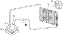
图1示出了使用冷却板的冷却系统。Figure 1 shows a cooling system using cooling plates.
图2是冷却板的一个实施方案的分解图。Figure 2 is an exploded view of one embodiment of a cooling plate.
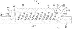
图3是冷却板的一个实施方案的横截面侧视图。Figure 3 is a cross-sectional side view of one embodiment of a cooling plate.
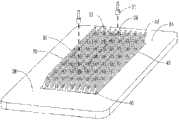
图4是底板的透视图。Figure 4 is a perspective view of the bottom plate.
图5是具有不同引脚模式的底板的透视图。Figure 5 is a perspective view of a backplane with different pin patterns.
图6是作为底板的部分的两个引脚的部分横截面侧视图。Figure 6 is a partial cross-sectional side view of two pins that are part of the backplane.
图7是一个引脚的侧视图。Figure 7 is a side view of a pin.
图8是切成四块的一个引脚的透视图。Figure 8 is a perspective view of a pin cut into four pieces.
图9是在底板中形成鳍片的工具的透视图。Figure 9 is a perspective view of a tool for forming fins in a base plate.
图10是在底板中形成鳍片的工具的侧视横截面图。Figure 10 is a side cross-sectional view of a tool for forming fins in a base plate.
图11是在底板中以不同角度形成鳍片的工具的侧横截面图。Figure 11 is a side cross-sectional view of a tool for forming fins in a base plate at different angles.
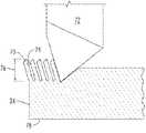
图12是从鳍片形成引脚的工具的透视图。Figure 12 is a perspective view of a tool for forming pins from fins.
具体实施方式Detailed ways
一些电子组件受其产生的热限制。冷却可帮助增加一些这些组件的利用。不同冷却技术更适于不同设备或不同情况。一种冷却方法使用风扇在电子组件上吹气以对流冷却。这种技术简单且安全,但并不提供一些其它技术的冷却潜力。利用液体冷却剂可提供更有效的冷却,但当以液体喷溅时,许多电子组件可能发生故障,所以当使用液体冷却时一些组件可能要慎重。尽管如此,液体冷却可增加一些电子组件的整体效率,并且提供某些其它优点。次要优点可包括电子组件中减少的声学噪音和优异的温度一致性。Some electronic components are limited by the heat they generate. Cooling can help increase utilization of some of these components. Different cooling technologies are more suitable for different equipment or different situations. One cooling method uses a fan to blow air over electronic components for convective cooling. This technique is simple and safe, but does not offer the cooling potential of some other techniques. Utilizing liquid coolant can provide more efficient cooling, but many electronic components can fail when splashed with liquid, so some components may be cautious when using liquid cooling. Nonetheless, liquid cooling can increase the overall efficiency of some electronic components and provide certain other advantages. Secondary benefits may include reduced acoustic noise and excellent temperature uniformity in electronic assemblies.
热传递基础heat transfer basics
本描述将关注单相热传递。应当认识到冷却板和其它热传递装置可用于双相冷却,且本发明不限于单相冷却,但本描述为简单和清晰起见而关注单相热传递。This description will focus on single phase heat transfer. It should be recognized that cooling plates and other heat transfer devices may be used for two-phase cooling, and that the invention is not limited to single-phase cooling, but this description focuses on single-phase heat transfer for simplicity and clarity.
空气或其它气体可用作冷却板中的冷却媒体,但液体是优选的。出于若干原因,液体冷却不同于气体冷却。例如,液体比气体更稠密,所以可用更多热质以从电子设备吸收热。另外,液体一般具有较高导热率,所以热会传递到液体中且经过该液体比热会传递到气体中且经过气体更快速。此外,液体趋于具有比气体更高的比热,所以设置量的液体将比相当量的气体吸收和传递更多热。因此,当利用产生大量热的电子设备时,许多制造商可选择液体冷却装置。Air or other gases can be used as the cooling medium in the cooling plate, but liquids are preferred. Liquid cooling differs from gas cooling for several reasons. For example, liquids are denser than gases, so more thermal mass is available to absorb heat from electronic devices. Additionally, liquids generally have a higher thermal conductivity, so heat will transfer into and through a liquid more quickly than heat will transfer into and through a gas. Additionally, liquids tend to have higher specific heats than gases, so a given amount of liquid will absorb and transfer more heat than an equivalent amount of gas. Therefore, many manufacturers have opted for liquid cooling when utilizing electronic equipment that generates a lot of heat.
减小热流的阻力改进了热传递装置的效率。热流阻力的两个显著形式包括经过一种材料的阻力和跨越两个单独组件或部件之间的界面的阻力。如果所述材料是导热体,而不是绝热体,那么经过单个材料的热流阻力被最小化。金属通常是相对良好的导体,且其可以许多方式予以形成和塑形。铜是容易导热的金属,且其相对可延展,所以铜常常用于冷却板中。然而,也可以使用其它材料,诸如铝、钛、钢、金或甚至非金属材料,如石墨或陶瓷。Reducing the resistance to heat flow improves the efficiency of the heat transfer device. Two significant forms of heat flow resistance include resistance through a material and resistance across an interface between two separate components or components. If the material is a heat conductor rather than a heat insulator, the resistance to heat flow through the individual material is minimized. Metals are generally relatively good conductors, and they can be formed and shaped in many ways. Copper is a metal that conducts heat easily, and it is relatively ductile, so copper is often used in cooling plates. However, other materials may also be used, such as aluminum, titanium, steel, gold or even non-metallic materials such as graphite or ceramics.
热流阻力的另一来源在两个组件或部件之间的界面处。通常,当热从第一组件流动到接触该第一组件的另一组件时,所述两个组件之间存在热流阻力。从一个固体基板形成热传递装置可帮助改进热传递。如果要单独制造一个热传递组件,且接着将该组件粘附到另一个,那么所述两个组件之间的接缝处将具有热流阻力。即使所述单独组件由相同材料(诸如铜)制成,这也是确实的。从较少组件形成热传递装置可改进热传递。在本描述中,当一块从另一块形成,所以两者之间没有接缝时,所述块被认为是单片的。Another source of resistance to heat flow is at the interface between two components or components. Typically, when heat flows from a first component to another component that contacts the first component, there is a resistance to heat flow between the two components. Forming the heat transfer device from one solid substrate can help improve heat transfer. If one heat transfer component were to be manufactured separately and then adhered to the other, there would be resistance to heat flow at the seam between the two components. This is true even if the individual components are made of the same material, such as copper. Forming the heat transfer device from fewer components can improve heat transfer. In this description, a piece is said to be monolithic when it is formed from another piece so that there is no seam between the two.
也可通过增加两个不同材料彼此接触的表面积而改进热流。当液体在固体上流动时,热在所述液体接触所述固体之处的两个材料之间传递。增加液体接触固体之处的表面积是减少热传递阻力,且增加热传递装置的效率的另一方式。Heat flow can also be improved by increasing the surface area over which two dissimilar materials contact each other. When a liquid flows over a solid, heat is transferred between the two materials where the liquid contacts the solid. Increasing the surface area where the liquid contacts the solid is another way to reduce the resistance to heat transfer and increase the efficiency of the heat transfer device.
在一些情况中,液体将跨越固体流动,其称为层流。在层流中,直接接触固体表面的液体层在固体表面基本上保持静止。直接在所述层上方的液体层跨越第一层非常缓慢地移动。下个层略微更迅速地向上移动,等等,使得最高流速将在相对远离固体表面的点处。基本上为零的最低流速将在固体表面处。在邻近层上滑动的每个不同液体层提供其自身的热流阻力。因此,如果在流动期间可混合液体,那么直接接触固体表面的液体可从该固体表面吸收热,且接着与整体冷却液体混合,以更快地将吸收的热散到液体中。In some cases, liquids will flow across solids, which is called laminar flow. In laminar flow, a liquid layer in direct contact with a solid surface remains substantially stationary on the solid surface. The liquid layer directly above the layer moves very slowly across the first layer. The next layer moves up slightly more rapidly, etc., so that the highest flow velocity will be at a point relatively far from the solid surface. The lowest flow rate, essentially zero, will be at the solid surface. Each distinct layer of liquid sliding over an adjacent layer provides its own resistance to heat flow. Thus, if the liquids can be mixed during flow, the liquid in direct contact with the solid surface can absorb heat from the solid surface and then mix with the bulk cooling liquid to more quickly dissipate the absorbed heat into the liquid.
与层流相反,湍流造成液体随其流动跨越固态表面而混合。这趋于将液体保持与固态表面冷却器接触,其促进从固态表面到液体的更快热传递。趋于增加湍流的一些事物包括更快的流速、不平坦的表面、流动液体中的凸出物和迫使液体改变路径且流到另一通路的各种障碍物。为了使湍流最大化,事物可包括急弯、扭转边缘、弯曲支柱和在液体流动方向上造成快速变化的任何各种流动障碍物。增加湍流的许多结构还可增加跨越冷却板的压力降。增加的压力将可降低流速,所以必须遵守平衡以确保有效热传递。趋于增加接近固体表面的流体流量的障碍物也趋于增加热传递,因为这会减小固体液体界面的任何停滞液体层的厚度,并且其还减小加热的液体必须行进以与冷却液体的主体混杂的距离。In contrast to laminar flow, turbulent flow causes liquids to mix as they flow across solid surfaces. This tends to keep the liquid in contact with the solid surface cooler, which promotes faster heat transfer from the solid surface to the liquid. Some things that tend to increase turbulence include faster flow velocities, uneven surfaces, protrusions in the flowing liquid, and various obstacles that force the liquid to change course and flow to another pathway. To maximize turbulence, things can include sharp bends, twisting edges, curved struts, and any of a variety of flow obstructions that cause rapid changes in the direction of liquid flow. Many structures that increase turbulence can also increase the pressure drop across the cooling plate. Increased pressure will reduce the flow rate, so a balance must be observed to ensure efficient heat transfer. Obstacles that tend to increase fluid flow close to a solid surface also tend to increase heat transfer, as this reduces the thickness of any stagnant liquid layer at the solid-liquid interface, and it also reduces the distance the heated liquid must travel to meet the cooling liquid. The distance of subject clutter.
冷却板冷却系统Cooling plate cooling system
如第1图所见,冷却板10可连接到电子组件12或一些其它装置,以帮助冷却该电子组件12或其它装置。该冷却板10还可以用来以与冷却装置相同的方式加热装置,但为了简单和清晰起见,本描述是关于冷却。冷却液体(也称为冷却剂)用于从热源,诸如电子组件12吸收热。在冷却剂吸收热之后,其可在被重新用于冷却之前循环到该冷却剂自身被冷却的不同位置。在一个实施方案中,风扇14在类似于汽车散热器的对流冷却装置16上吹冷气,冷却剂经过该对流冷却装置循环。可代替该对流冷却装置16而使用使用厂务水或其它冷却系统的热交换器。也可诸如通过经由暴露至比冷却剂更冷的空气的管道而泵送冷却剂,而仅仅将加热的流体简单移动经过冷却器区。As seen in FIG. 1 , a cooling
泵18或其它引流装置可使冷却剂循环经过冷却板10。诸如用粘合剂、声波熔接、硬焊、焊接、扩散接合或任何其它适当技术而将冷却板10粘附到电子组件12。某些粘合剂容易导热,且可帮助使热流阻力最小化。冷却板10直接连接到电子组件12可最小化热传递阻力。在冷却板10与电子组件12之间使用热电冷却器可改进性能,但热电冷却器超出本讨论。在一个实施方案中,由电子组件12产生的热被传递到板10中的冷却剂,且该冷却剂接着被泵送到以来自风扇14的空气冷却的对流冷却装置16。可将多个冷却板10或其它热交换器装置连接在单个环路中,使得若干电子组件12或其它产热装置可用单个泵18和对流冷却装置16冷却。例如,汽车可使用水泵18以经过发动机机体输送防冻剂(冷却剂)来冷却该发动机,而且还将防冻剂输送到水障10,以冷却电子组件12。A
也可以使用蒸发冷却,其中液体由来自电子组件12或其它热源的热蒸发。通常,液体在蒸发器中蒸发成气体,且接着该气体在冷凝器中重新冷凝成液体。也可从系统蒸发和排出液体。冷却板10可用作蒸发器和/或冷凝器。许多材料可使用为冷却剂,包括水、水和乙二醇混合物、氯氟碳化物(CFC)、氢氯氟碳化物(HCFC)、氨、盐水溶液、油和许多其它材料。Evaporative cooling may also be used, in which liquid is evaporated by heat from the electronic assembly 12 or other heat source. Typically, a liquid is evaporated into a gas in an evaporator, and then the gas is recondensed into a liquid in a condenser. It can also evaporate and drain liquid from the system. The cooling
冷却板cooling plate
继续参考第1图,如第2图、第3图和第4图中所见,冷却板10包括若干结构组件。冷却板10中的冷却剂流经外壳20,且外壳20具有基底22和盖24。外壳20通常还将包括侧壁26。基底22在外壳10的底部,且盖24在顶部。可将侧壁26并入为用于制作盖24的单个结构的一部分,或侧壁26可为单独的结构,或者所述侧壁可为基底20的部分。基底22和盖24也可逐渐倾斜在一起,所以侧壁26与基底22和/或盖24之间没有清晰分界。外壳20几乎可以是任何形状,所以如果该外壳是圆形或圆柱形,那么侧壁26可以是一个连续壁。Continuing with reference to FIG. 1 , as seen in FIGS. 2 , 3 and 4 , cooling
冷却剂或其它流体经过入口28和出口30进入和离开外壳20。入口28和/或出口30可穿透盖24、侧壁26或基底22,只要入口28和出口30允许流体进入和离开外壳20。所述入口28和出口30流体连通经过外壳20,所以流体经过入口28进入外壳20,行经外壳20,且接着经出口30离开该外壳20。此流动方向也可相反。也可具有多于一个入口28和/或多于一个出口28。可将喷嘴31或类似装置在所述入口28和/或出口30处连接到冷却板10以促进流体流动。Coolant or other fluid enters and exits
入口28和出口28的定位会影响经过外壳20的流动模式。继续参考第1图到第4图,如第5图中所见,流线32定义为一条在入口28与出口30之间为笔直的线。在一些实施方案中,流动模式将趋于遵循流线32,但外壳20内的一些结构可能改变流动模式。入口28和/或出口30穿透到外壳20中的角度也可影响流动模式,因为入口28可用作喷口来引导流动,且出口可用作排水口来引导流动。所述入口28和/或出口30的位置也可影响流动模式,而且可搭配入口28和/或出口30穿透该外壳20的角度利用此来建立更希望的流动模式。在一些实施方案中,希望覆盖基底22的大部分的流动模式使由流动流体冷却的面积最大化。The positioning of the
外壳20的基底22由底板34形成。该底板34包括岛状物36,该岛状物36在底板34面向该外壳20内的侧上。在一些实施方案中,底板背侧78,或底板34相对该岛状物36的侧被附接到电子组件12或其它产热装置。如果希望,也可将冷却板10的不同部分附接到产热装置。The
底板34可包括绕岛状物36以附接侧壁26和/或盖24的附接区38。底板34到盖24或侧壁26的连接应为防水的,以防止液体泄漏(如果冷却流体是液体)。该附接区38的平滑表面可促进防水连接,但其它表面可能也是有用的。该附接区38可在所述盖24或侧壁26上包括具有匹配唇缘的凹槽,或与粘合剂一起使用的粗糙表面,或任何各种其它选择。在一些实施方案中,盖24和/或侧壁26完全绕底板34滑动,所以附接区38可在面对垂直于岛状物36的表面的底板34的表面的侧路上。在其它实施方案中,可提高附接区38,所以扁平盖24可完成外壳20。各种设计选择可用于该附接区38。The
从岛状物36延伸的多个引脚40朝盖24向上。所述引脚40可一直延伸到盖24,所以引脚实际上触碰该盖24,或所述引脚40可延伸到尚未到该盖24的某点处,所以所述引脚40与盖24之间存在间隙。冷却板10中的引脚40以某种模式排列。该模式可以是随机的,或该模式可以是有序的。在一个实施方案中,如第5图中所示出,所述引脚40沿着与流线32平行的线对准。此模式称为对准模式。将所述引脚40与流线32对准趋于引起冷却剂在引脚40的不同行之间流动。此流动可帮助减小冷却板10中的压力降。对准模式的引脚40的螺旋可对冷却板10提供与具有波纹鳍片设计的冷却板10的一些类似之处。在替代实施方案中,如第4图中所示出,引脚10在与流线32交叉的行上对准。此模式称为交错模式。引脚10的行可设置为与该流线32呈几乎任何角度,诸如四十五度角、三十度角或基本上任何其它角度。在交错模式中,流体被迫绕交错引脚流动,所以流体可能不在与流线32平行的直线上流动。此趋于造成锯齿形流动模式,其趋于增加湍流且还增加跨越冷却板10的压力降。A plurality of
引脚形状Pin shape
继续参考第1图到第5图,如第6图、第7图和第8图中所见,引脚40具有一个形状,且该形状可影响冷却板10的热传递效率。所述引脚40具有引脚底部42,其是引脚40附接到底板34的岛状物36之处,且所述引脚40在引脚40与该引脚底部42相对的端具有顶部44。所以,顶部44一般是引脚40最接近盖24的部分。引脚长度46是从引脚底部42测量到引脚顶部44,且引脚轴48从引脚40的中心部分往下延伸。该轴48延伸穿过引脚40的中心,所以该轴48将位于引脚40的任何横截面的中心点。该引脚40还包括侧表面50,其是引脚40的从底部42延伸到顶部44的侧上的外表面。Continuing to refer to FIGS. 1-5 , as seen in FIGS. 6 , 7 and 8 , the
每个引脚40具有横截面轮廓52,其中横截面垂直于轴48。该横截面轮廓52是横截面的形状。此横截面轮廓52可为许多不同形状,但在一些实施方案中,其一般是四边形。每个横截面轮廓52还具有横截面定向54,其指横截面所面对的方向。四边形或任何其它形状不具有清晰的设置前端,但沿着该横截面的周界的任何边或点可被选为横截面定向54的参考点。该横截面轮廓52可沿着引脚长度46变化,所以该引脚40的全长度46的大小或一般形状不需要为固定和恒定。该横截面还具有横截面积56,其是横截面的面积。该横截面积56也可沿着引脚40的长度46改变,所以该引脚40可在沿着该引脚长度46的不同点处变宽或变窄。Each
本发明的引脚40具有一些特定的结构方面。在一个实施方案中,引脚40具有螺旋形状。横截面定向54沿着引脚长度46变化,且用于横截面定向54的参考点趋于始终在相同方向上从引脚底部42移动到顶部44。横截面定向54可能不沿着整个引脚长度46变化,但其确实沿着引脚长度46的一部分变化。此给予引脚40的至少一部分螺旋的外观。在其它实施方案中,参考点可对于引脚40的一个部分在一个方向上移动,对于该引脚40的不同部分在另一方向上移动,且对于该引脚40的又一不同部分可能不移动。多面体形状,诸如四边形引起沿着引脚侧表面50的边缘。沿着引脚长度46变化的横截面定向54引起沿着该引脚长度46变化位置的边缘。所述边缘中的此变动可增加绕引脚40流动的流体中的湍流,且可因此改进冷却板10的效率。如在下文中更详细讨论,也可通过预置用于形成引脚40的切割工具的角度而操作该引脚40的倾斜角。The
在一些实施方案中引脚40还可具有弯曲。当沿着引脚长度46的轴48弯曲时,该引脚40被认为是弯曲的。由于沿着引脚长度46的引脚的横截面轮廓52中的可能变化,引脚40的一侧可显得相对笔直,且另一侧显得弯曲,但引脚40的轴48仍然沿着该引脚长度46弯曲。在一些实施方案中,引脚40的弯曲形状显得类似于香蕉,然而在不同实施方案中,引脚40的外观会变化。在一些实施方案中,靠近引脚顶部44处存在“鱼钩”59,其中该鱼钩59是引脚40的更急剧弯曲的部分;然而在其它实施方案中,不存在鱼钩形状。鱼钩59在某种程度上看起来像香蕉茎干。引脚40的弯曲形状为在周围流动的流体呈现具有变化形状的障碍物,这可增加冷却板10中的湍流。该弯曲形状可引导流体向上和/或向下流动,以进一步改变流体流动模式,且借此可增加湍流。向下朝底板34引导的流体流动更靠近于可能是冷却板10的最热部分。更靠近于引脚底部42的这种增加的流动可增加热传递。在靠近引脚底部42的冷却板10的固体材料与附近流动的混合冷却剂之间可能存在较大温差,且增加的温差可能增加整体冷却板效率。The
在其它实施方案中,引脚40在侧表面50上可具有至少两个不同纹理58。这些纹理58的至少一个包括凹痕60,且可在某种程度上显得像橘皮。所述凹痕60是从表面延伸至少一些距离到引脚40中的压痕。不同纹理58可在引脚40的四边形或多面体形状的不同面上。在一些实施方案中,侧表面50将包括至少三个不同纹理,且沿着引脚40的多面体形状的一面可具有两个不同纹理58。不同表面纹理58提供可造成湍流和帮助增加热传递的附加结构。所述凹痕60提供变化的表面结构,其确实趋于增加流经引脚10的流体中的湍流,且纹理中的变化也可造成起湍流。In other embodiments, pin 40 may have at least two
在一些实施方案中,引脚40还可具有沿着引脚长度46变化的厚度。所述引脚40在引脚底部42处可为锥形,所以该引脚40的厚度更接近于该引脚底部42时减少。更技术上而言,对于引脚40的至少一部分,横截面积56可随着自引脚底部42的距离的增加而增加。这符合引脚40的香蕉形状,因为香蕉趋于在靠近香蕉与茎干相对的端处渐缩。这可引起引脚40在中间或顶部44比在引脚底部42更厚。在靠近引脚底部42处提供比该引脚40的较高处更多的流体流动空间促使流体更接近引脚底部42和底板34而流动。该底板34可连接到要被冷却的产热物体,所以在靠近该底板34处增加的流体流动可增加热传递效率。在其它实施方案中,离底部42越远,引脚40不会变的越厚,所以存在的任何锥形是引脚40从底部42进行到顶部40的变薄。In some embodiments, the
在一些实施方案中,引脚40可为具有底板34的单片,这意味着引脚40与底板34之间没有接缝。这可通过直接由底板34形成引脚40来实现,而不是分开形成引脚40,且接着以某种方式将该引脚40固定到该底板34。使引脚40与底板34成一体后,可通过减小从底板34向上到引脚40的热流阻力而增加热传递。随着热向上流动到引脚40,经过该引脚40的流体流动从该引脚40吸收热,且增加冷却板10的整体热传递效率。所述引脚40提供用于从底板34的热传递的附加表面积,且该底板34与所述引脚40之间的低热流阻力增加了整体热传递效率。In some embodiments, the
所述引脚40在一些实施方案中可包括二十比一的长宽比,其中引脚长度46是跨越该引脚40或引脚宽度62的距离的二十倍。通过增加长宽比,热传递会增加,因为具有相同宽度62的更长引脚40趋于具有更大表面积,且增加的表面积趋于增加热传递效率。The
上文描述的引脚形状的各个方面可孤立或以任何组合存在于所述引脚40中。这包括四边形横截面、螺旋形状、弯曲形状、多个纹理、锥形形状、到底板的单片连接、倾斜角和长宽比。尤其取决于制造技术和希望的热传递性质的因素,每个引脚40可仅仅包括这些结构之一,或所述结构的任何组合。The various aspects of pin shape described above may be present in the
底板的制造方法Manufacturing method of base plate
继续参考第1图到第8图,如第9图到第12图中所见,本发明还包括一种制造冷却板10的方法。该冷却板10通过制备底板34,且将盖24附接到该底板34而构造。也可存在其它结构,诸如单独的侧壁26。将盖24附接到底板34,使得外壳20定位于该盖24与底板34之间。标准制造技术可用于制造盖24和侧壁26。其包括冲压、切割、铸造、金属注射成型、机械加工和其它技术。盖24和底板34也可由许多标准技术予以接合,诸如硬焊、熔焊、焊接、胶合和其它连接方法。Continuing to refer to FIGS. 1-8 , as seen in FIGS. 9-12 , the present invention also includes a method of making a
底板34的制造需要附加步骤。引脚40通过首先将鳍片70分割成底板34,且接着跨越鳍片70执行第二组分割而制造。所述第二组分割基本上交叉切割所述鳍片,且此交叉切割产生所述引脚40。用于分割该底板34的一个程序称作微变形技术(MDT),且其描述于1998年7月7日授证的美国专利5,775,187中,其全部并入本描述中。在此程序中,在没有将材料从底板34移除的情况下,用工具72分割底板34。该MDT程序不同于锯子或导引器,其随着切割的进行而移除材料,且更类似于用刀切割肉。The manufacture of
底板34的分割是用工具72完成。随着工具72接触底板34的材料,从材料的主块切割鳍片70。这在邻近鳍片70之间形成通道74,且可在没有将材料从底板34移除的情况下完成。优选的是,在形成所述鳍片70时没有产生剃屑。该工具72在底板34中切割鳍片70,且该工具72经过底板34材料时所产生的空间使鳍片70中的材料变形且迫使其向上。底板34材料的这种切割和变形造成鳍片70上升到比原始底板34更高的鳍片高度76。MDT切割工具设计、切割深度、鳍片70和通道74的宽度是影响鳍片高度76的因素。重复此程序,直到已经产生鳍片70的床。Separation of
引脚40是通过跨越鳍片70分割而制作。第二组分割也可使用MDT方法,且将所述引脚40提高到大于鳍片高度76的长度46。随着分割的进行,没有从底板34移材料除,所以移动的材料取而代之被引导到剩余引脚40或鳍片70中。这造成所述剩余引脚40或鳍片70提高到高于从其切割引脚40或鳍片70的材料的高度。所述第二组分割可以与所述鳍片70呈除了九十度之外的角度进行,但已经发现当使用除了约九十度之外的角度时,引脚长度46趋于改变。如果希望,可以变化的引脚长度46制作冷却板10,或者所述引脚长度46可通过与所述鳍片70呈约九十度进行第二组分割而保持更一致。在替代实施方案中,在没有使用MDT程序的情况下制作鳍片70,且接着使用MDT程序从所述鳍片70形成引脚40。在另一替代实施方案中,使用MDT程序制作鳍片70,且接着使用常见切割程序从鳍片70形成引脚40。这可产生非螺旋结构的引脚40。
交叉分割底板34来制造引脚40的技术促成引脚40的最终形状。第一次分割使得鳍片70具有两个平坦侧,且第二次分割趋于使得引脚40具有另外两个平坦侧,总共有四个相对平坦的侧。所述四个相对平坦侧为引脚40产生四边形横截面轮廓52。该四边形横截面轮廓52在不同侧表面50之间提供边缘,其趋于在这些边缘上流动的流体中增加湍流。此外,如上文所讨论,从底板34分割引脚40引起所述引脚40与该底板34成一体,这改进了热传递。此外,引脚40和/或鳍片70的倾斜角可随着分割的进行而由工具72的角度来操作。鳍片70的倾斜角的修改可改变引脚40的倾斜角。The technique of
工具72在底板34材料上的切割动作在切割该地板34时对材料提供不同纹理。被切割且上推以形成鳍片70或引脚40的表面采用工具72的切割表面的纹理,其可以是非常平滑的。工具的相对侧上的底板表面只是将材料从其切除,且这趋于产生橘皮纹理58,或包括多个凹痕60的纹理。这引起跨越通道74彼此面对的两个表面具有不同纹理58。在进行任何分割之前,底板34的原始表面纹理58也保留在引脚40的一部分上。原始底板表面在鳍片70中被切割且抬高,且接着在第二组分割中其被再次切割和抬高,以形成引脚40。这种表面纹理58保留在引脚40的一部分上,其可在引脚上提供第三纹理58。通过在流体流动模式中提供变化,引脚侧表面50上的不同纹理58可增加湍流。凹痕60尤其趋于比平滑表面更加会引起造成漩涡、混合和湍流。The cutting action of the
从鳍片70分割引脚40提供弯曲形状的引脚40,且还可提供螺旋形状的引脚40。所述鳍片70是独立式的,所以工具72的切割动作趋于随其切割而将引脚40弯曲。鳍片70在靠近引脚底部42处更稳定,因为这个部分被附接到底板34。鳍片70的较高部分不具有较低部分的支撑,且这些较高部分趋于随着切割和形成引脚40而弯曲。工具72仅随形成引脚40而在该引脚40的一侧上切割,使得弯曲力仅仅施加到所述引脚40的一侧。因为该弯曲力仅施加到所述引脚40的一侧,所以该弯曲力的一部分可用于扭转该引脚40,引起螺旋效果。如上文所讨论,弯曲且螺旋形的引脚40可增加湍流且迫使流动更接近于底板34,其可增加热传递效率。可帮助将冷却板10的流动路径保持更充分敞开的一个方法是以与最终流线32基本上垂直的方向分割所述鳍片70,且接着进行二次分割以形成基本上平行于该流线32的引脚40。Splitting the lead 40 from the
引脚40的锥形和香蕉形状也可源自MDT方法的分割。在进行切割时,新形成的鳍片70或引脚40被向上推动以配合由切割动作移动的材料。靠近引脚底部42的材料被向上推动到引脚40的本体中,且可引起所述引脚40的更厚中心部分。此更厚中心部分提供引脚底部42的锥形形状,而且还可提供靠近引脚顶部44的相对锥形。工具72也可随其经过而捕获鳍片70的顶部,且更容易地模制此较薄材料,使得形成鱼钩59。如果希望,可通过在第二次切割程序之前修剪掉鳍片70的尖部来除去该鱼钩59,或者该鱼钩59可被保留在适当位置。此鳍片修剪程序也帮助控制最终的引脚长度46。The tapered and banana shapes of the
首先形成鳍片70,且接着形成引脚40的双重交叉分割将材料推动到引脚40中。如上文所述,此技术已经用于制造二十比一的长宽比。利用工具72的分割可使用利用各种机器的已知技术来完成,所述机器包括但不限于铣床、整形器或甚至车床。分割底板34可提供制造冷却板10的引脚40的有效、相对低成本的方法。The
冷却板的制造方法Manufacturing method of cooling plate
在形成引脚40的岛状物36后,可准备将底板34组装到冷却板10中。可能经过侧壁26块而将盖24附接到该底板34,以形成外壳20。入口28和出口30穿透到该外壳20中以提供冷却剂或其它流体的通路。所述入口28和出口30可在组装底板34和盖24之前或之后制造。喷嘴31可被附接到所述入口28和/或出口30以促进流体流动,且所述入口28和出口30的形状可变化。例如,所述入口28和出口30可为圆孔,正方形孔、覆盖冷却板10的整个侧的歧管,或任何各种其它形状。所述入口28和出口30可被钻孔、冲压、切割或以许多已知技术制造。After the
为制备底板34以容纳盖24或侧壁26,制造附接区38。该附接区38可以若干不同方式制造。在一个实施方案中,底板34的整个上表面形成为引脚40,且该底板34的侧表面用作附接区38。在替代实施方案中,附接区38形成于底板34的上表面的外边缘上,其中引脚40的岛状物36定位于附接区38内部。在一个实施方案中,在底板34的整个上表面形成为引脚40之后,可通过机械加工而形成附接区38。在替代实施方案中,在形成引脚40之前,可将附接区38机械加工成比岛状物36更低水平,且工具72的分割被设置为忽略附接区38。以此方式,在没有破坏附接区38的表面的情况下,在该附接区38内部形成引脚40的岛状物36。也可用使用已知技术的各种其它选择来制造附接区38。如上文所讨论,附接区38可取决于将要进行的附接类型而采用许多形式。To prepare the
引脚40在冷却板10中的对准可变化,包括对准模式或交错模式。对于矩形冷却板10,可通过将鳍片70和引脚40分割成垂直于矩形底板34的边缘的多个片而进行对准模式。接着构造该冷却板10且使入口28和出口30沿着该底板34的一个边缘居中。可用与用于对准模式相同的底板34进行交错引脚模式,其中该底板34的角被移除以产生新边缘。这些新边缘不再与分割到底板中的引脚40对齐,且可如前文构造冷却板10。在替代实施方案中,可通过与底板34的边缘呈角度分割鳍片70和引脚40而进行交错引脚模式。对于鳍片70和引脚40的交叉分割可以仍然呈九十度,但是所得引脚模式在行上不平行且垂直于底板34的边缘。也可使用其它方法和技术来制造不同模式的引脚40。The alignment of
底板34的背侧78(其相对于引脚40)可能需要为非常平坦的,以与将要冷却的电子组件12或其它物体进行良好热连接。可期望在使用冷却板10之前采取步骤将该底板背侧78平坦化。可以若干方式平坦化此背侧78,且其可在形成所述引脚40之前或之后被平坦化。在一些实施方案中,在形成所述引脚40之后平坦化背侧78,以校正形成所述引脚40时可能出现的任何翘曲或弯曲。可用已知技术来制造底板34的平坦背侧78。在形成引脚40后将底板34的背侧78平坦化的实施方案中,可采用措施来防止对所述引脚40的损害。这可包括悬挂所述引脚40的夹具,同时机械加工该底板34的背侧78,和/或可采用真空系统以固定该底板34用于随后平坦化。The
尺寸、用途和实施例Dimensions, Uses and Examples
冷却板10可用于许多不同目的。不同设计更好地适于不同目的。例如,如果冷却板10用于具有引擎冷却剂流体的机动车辆中,那么该冷却板10应被设计成经受住冷却剂中的一些微粒。如果该冷却板10用于具有非常干净、经过过滤的冷却剂的计算机中,那么微粒问题并不那么重要。下文讨论的尺寸可搭配使用具有直径上多达一毫米的微粒的冷却剂。Cooling
在冷却板10的一个实施方案中,外壳20经过定大小使得引脚40基本上接触盖24。所述引脚40约为五毫米高且约为一毫米宽。邻近引脚40之间的间隙约为一毫米,且总冷却板大小约为十五厘米乘以十五厘米。In one embodiment of cooling
已用计算机模拟建模三个不同冷却板10的性能。在模型中,第一冷却板10包括鳍片70,第二冷却板10包括具有对准模式的引脚40,且第三冷却板10包括具有交错模式的引脚40。该模型中的引脚40包括如本描述中描述的螺旋和弯曲。The performance of three
在所述三个计算机模型的每个中,冷却剂是乙二醇,其具有1,027千克每立方米(kg/m3)的密度、0.00169帕斯卡秒(Pa*s)的动力粘度、3,300焦耳/千克开氏度(J/(kg*K))的比热和0.388瓦特每米开氏度(W/(m*K))的导热率。该冷却剂经过冷却板10的流速是五升每分钟(1/min),且所述冷却剂在入口28处的温度是二十摄氏度(C)。热源是每个产生一百六十六瓦特(w)的三个组件,其中每个组件具有十五乘以十二毫米(mm)的面积,总共约五百瓦特(w)。该冷却剂相继流经每个热源。In each of the three computer models, the coolant is ethylene glycol, which has a density of 1,027 kilograms per cubic meter (kg/m3 ), a dynamic viscosity of 0.00169 Pascal seconds (Pa*s), 3,300 Joules/ A specific heat in kilograms Kelvin (J/(kg*K)) and a thermal conductivity of 0.388 watts per meter Kelvin (W/(m*K)). The flow rate of the coolant through the cooling
冷却板10的特定结构用于所述计算机模型中,且每个冷却板10具有相同的长度和宽度。具有鳍片70的第一冷却板10每英寸具有十个鳍片或每厘米约四个鳍片,其中鳍片厚度是一毫米,鳍片高度是四点七毫米,且邻近鳍片70之间的间隙是一毫米。引脚40处于对准模式的第二冷却板10每英寸具有十个引脚或每厘米约四个引脚,引脚厚度是一毫米,引脚高度是四点七毫米,且邻近引脚40之间的间隙是一毫米。引脚40处于交错模式的第三冷却板10每英寸具有十个引脚或每厘米约四个引脚,引脚厚度是一毫米,引脚高度是四点七毫米,且邻近引脚40之间的间隙是一毫米。The specific structure of the cooling
该模型计算每个热源的稳态温度。冷却剂相继流经所述三个热源,所以随着该冷却剂经过,每个热源增加该冷却剂的温度。因此,最接近入口28的第一热源由最冷的冷却剂冷却,且到达最冷的稳态温度。第三热源由已被前两个热源变暖的冷却剂冷却,所以该第三热源到达最热的稳态温度。第二热源介于第一与第三热源之间,所以该第二热源到达介于第一热源与第三热源的稳态温度之间的稳态温度。所述稳态温度以摄氏度列在下表中。该计算机模型也计算了跨越每个冷却板10的压力降,且该值以毫米汞柱列在下面。The model calculates the steady-state temperature for each heat source. The coolant flows sequentially through the three heat sources so that each heat source increases the temperature of the coolant as it passes. Thus, the first heat source closest to the
此模型示出了使用引脚40可增加超出使用鳍片70热传递效率。This model shows that the use of
发展更好的引脚40可甚至更多地增加热传递效率。Developing
虽然已参考有限数量的实施方案描述本发明,但是得益于本描述,所属领域技术人员将了解,可制定未脱离本文公开的本发明的范围的其它实施方案。While the invention has been described with reference to a limited number of embodiments, those skilled in the art will appreciate, having the benefit of this description, that other embodiments can be made without departing from the scope of the invention disclosed herein.
Claims (26)
Translated fromChineseApplications Claiming Priority (3)
| Application Number | Priority Date | Filing Date | Title |
|---|---|---|---|
| US12/573,107US20110079376A1 (en) | 2009-10-03 | 2009-10-03 | Cold plate with pins |
| US12/573,107 | 2009-10-03 | ||
| PCT/US2009/068591WO2011040938A1 (en) | 2009-10-03 | 2009-12-17 | Cold plate with pins |
Publications (2)
| Publication Number | Publication Date |
|---|---|
| CN102577653Atrue CN102577653A (en) | 2012-07-11 |
| CN102577653B CN102577653B (en) | 2017-06-30 |
Family
ID=43822294
Family Applications (1)
| Application Number | Title | Priority Date | Filing Date |
|---|---|---|---|
| CN200980162050.7AActiveCN102577653B (en) | 2009-10-03 | 2009-12-17 | Coldplate with pin |
Country Status (6)
| Country | Link |
|---|---|
| US (2) | US20110079376A1 (en) |
| EP (1) | EP2484190B1 (en) |
| JP (2) | JP2013506996A (en) |
| KR (1) | KR20120082891A (en) |
| CN (1) | CN102577653B (en) |
| WO (1) | WO2011040938A1 (en) |
Cited By (5)
| Publication number | Priority date | Publication date | Assignee | Title |
|---|---|---|---|---|
| CN106105410A (en)* | 2014-01-22 | 2016-11-09 | 高克联管件有限公司 | Double-sided micro-finned plates for plate heat exchangers |
| CN106642870A (en)* | 2017-01-24 | 2017-05-10 | 武汉攀升鼎承科技有限公司 | Three-dimensional type water cooling heat dissipation device |
| CN107743351A (en)* | 2013-01-31 | 2018-02-27 | 慧与发展有限责任合伙企业 | For providing the equipment, system and method for liquid cooling |
| US10571206B2 (en) | 2012-09-28 | 2020-02-25 | Hewlett Packard Enterprise Development Lp | Cooling assembly |
| CN110970681A (en)* | 2018-09-28 | 2020-04-07 | 罗伯特·博世有限公司 | Cooling plate for tempering at least one battery cell, and battery system |
Families Citing this family (52)
| Publication number | Priority date | Publication date | Assignee | Title |
|---|---|---|---|---|
| US10531594B2 (en) | 2010-07-28 | 2020-01-07 | Wieland Microcool, Llc | Method of producing a liquid cooled coldplate |
| US8712598B2 (en)* | 2011-01-14 | 2014-04-29 | Microsoft Corporation | Adaptive flow for thermal cooling of devices |
| EP2752104B1 (en)* | 2011-09-02 | 2022-05-04 | Wieland Microcool, LLC | Enhanced clad metal base plate assembly |
| US8519532B2 (en) | 2011-09-12 | 2013-08-27 | Infineon Technologies Ag | Semiconductor device including cladded base plate |
| US8963321B2 (en) | 2011-09-12 | 2015-02-24 | Infineon Technologies Ag | Semiconductor device including cladded base plate |
| US20130146268A1 (en)* | 2011-12-12 | 2013-06-13 | Unison Industries, Llc | Heat exchanger with fins and method for forming same |
| US10123464B2 (en) | 2012-02-09 | 2018-11-06 | Hewlett Packard Enterprise Development Lp | Heat dissipating system |
| DE102012014813B9 (en) | 2012-07-26 | 2016-06-16 | Wieland-Werke Ag | Structured heatsinks in modular design |
| WO2014018852A1 (en)* | 2012-07-27 | 2014-01-30 | Arizona Board Of Regents, A Body Corporate Of The State Of Arizona, Acting For And On Behalf Of Arizona State University | Cold plate for electronics cooling |
| JP2014075563A (en)* | 2012-10-02 | 2014-04-24 | Nakamura Mfg Co Ltd | Boiling heat transfer surface for ebullient cooler and forming method thereof |
| EP2915417B1 (en) | 2012-10-31 | 2017-11-29 | Hewlett-Packard Enterprise Development LP | Modular rack system |
| JP5523542B1 (en)* | 2012-12-07 | 2014-06-18 | 三菱電機株式会社 | Cooling system |
| JP6054423B2 (en)* | 2012-12-21 | 2016-12-27 | 京セラ株式会社 | Channel member, heat exchanger using the same, and semiconductor device |
| US9952004B2 (en)* | 2013-04-11 | 2018-04-24 | Solid State Cooling Systems | High efficiency thermal transfer plate |
| WO2015110865A1 (en) | 2014-01-22 | 2015-07-30 | Provides Metalmeccanica S.R.L. | Heat exchanger |
| JP6331771B2 (en)* | 2014-06-28 | 2018-05-30 | 日本電産株式会社 | Heat module |
| US10048019B2 (en)* | 2014-12-22 | 2018-08-14 | Hamilton Sundstrand Corporation | Pins for heat exchangers |
| CN108029219B (en)* | 2015-05-15 | 2020-04-24 | 维兰德微酷有限责任公司 | Liquid cooled cold plate and method of making same |
| EP3096352B1 (en)* | 2015-05-22 | 2018-02-21 | Alcatel Lucent | A heat transfer method and device |
| US11003227B2 (en) | 2015-06-03 | 2021-05-11 | Mitsubishi Electric Corporation | Liquid-type cooling apparatus and manufacturing method for heat radiation fin in liquid-type cooling apparatus |
| JP6503909B2 (en)* | 2015-06-12 | 2019-04-24 | 株式会社デンソー | Semiconductor device |
| JP6712915B2 (en)* | 2015-07-08 | 2020-06-24 | 株式会社フジクラ | Cold plate |
| US10225952B2 (en)* | 2015-10-28 | 2019-03-05 | International Business Machines Corporation | Cooling systems for cooling electronic components |
| US10991639B2 (en)* | 2016-04-01 | 2021-04-27 | International Business Machines Corporation | Compliant Pin Fin heat sink with base integral pins |
| CN105744805A (en)* | 2016-04-15 | 2016-07-06 | 周哲明 | Multi-channel combined water-cooling plate |
| JP6680160B2 (en)* | 2016-09-16 | 2020-04-15 | トヨタ自動車株式会社 | Boiling cooler |
| US10085362B2 (en) | 2016-09-30 | 2018-09-25 | International Business Machines Corporation | Cold plate device for a two-phase cooling system |
| WO2019100170A1 (en) | 2017-11-27 | 2019-05-31 | Dana Canada Corporation | Enhanced heat transfer surface |
| RU2679815C1 (en)* | 2017-12-28 | 2019-02-13 | федеральное государственное бюджетное образовательное учреждение высшего образования "Московский государственный технический университет имени Н.Э. Баумана (национальный исследовательский университет)" (МГТУ им. Н.Э. Баумана) | Method of the developed pin heat exchanging surface production |
| CN111954974B (en)* | 2018-03-13 | 2024-10-01 | 日产自动车株式会社 | Power Converter |
| US11391523B2 (en)* | 2018-03-23 | 2022-07-19 | Raytheon Technologies Corporation | Asymmetric application of cooling features for a cast plate heat exchanger |
| US10834847B1 (en) | 2018-03-26 | 2020-11-10 | Juniper Networks, Inc | Apparatus, system, and method for increasing the cooling efficiency of cold plate devices |
| US11071234B2 (en)* | 2018-10-30 | 2021-07-20 | Board Of Trastees Of The University Of Arkansas | Helical fin design by additive manufacturing of metal for enhanced heat sink for electronics cooling |
| DE102018222748B4 (en)* | 2018-12-21 | 2023-05-17 | Vitesco Technologies Germany Gmbh | cooler |
| US10874030B2 (en)* | 2018-12-26 | 2020-12-22 | Quanta Computer Inc. | Flexible cold plate with fluid distribution mechanism |
| WO2020146204A1 (en)* | 2019-01-10 | 2020-07-16 | Cree Fayetteville, Inc. | High power multilayer module having low inductance and fast switching for paralleling power devices |
| DE102019202902A1 (en)* | 2019-03-04 | 2020-09-10 | Abb Schweiz Ag | Direct cooling of a converter using an embossed plate |
| GB2584991B (en)* | 2019-05-21 | 2022-01-26 | Iceotope Group Ltd | Cold plate |
| WO2021145663A1 (en) | 2020-01-15 | 2021-07-22 | 주식회사 케이엠더블유 | Cooling apparatus for electronic element |
| US11434561B2 (en)* | 2020-03-27 | 2022-09-06 | STATS ChipPAC Pte. Ltd. | Cooling device and process for cooling double-sided SiP devices during sputtering |
| TWI719884B (en)* | 2020-04-13 | 2021-02-21 | 萬在工業股份有限公司 | Gravity-type high-efficiency heat-exchange device |
| CN112105235A (en)* | 2020-09-22 | 2020-12-18 | 浙江嘉熙科技有限公司 | Plate-tube combined heat dissipation structure and electronic equipment |
| US11576280B2 (en) | 2021-02-12 | 2023-02-07 | Raytheon Company | Cold plate branching flow pattern |
| US11583929B2 (en) | 2021-02-12 | 2023-02-21 | Raytheon Company | Cold plate design features amenable for additive manufacturing powder removal |
| EP4050295A1 (en) | 2021-02-26 | 2022-08-31 | Ovh | Water block having hollow fins |
| US11175102B1 (en)* | 2021-04-15 | 2021-11-16 | Chilldyne, Inc. | Liquid-cooled cold plate |
| US20230126158A1 (en)* | 2021-10-27 | 2023-04-27 | Carrier Corporation | Enhanced channel configuration for heat exchanger to cool power electronics |
| CN114518795A (en)* | 2022-02-28 | 2022-05-20 | 英业达科技有限公司 | Water cooling plate assembly |
| JPWO2024262175A1 (en)* | 2023-06-20 | 2024-12-26 | ||
| JP7434654B1 (en) | 2023-07-31 | 2024-02-20 | 古河電気工業株式会社 | Cold plate and cold plate manufacturing method |
| WO2025154496A1 (en)* | 2024-01-19 | 2025-07-24 | パナソニックIpマネジメント株式会社 | Temperature control structure |
| US12435732B1 (en) | 2024-09-19 | 2025-10-07 | Microsoft Technology Licensing, Llc | Centrifugal blower housing |
Citations (6)
| Publication number | Priority date | Publication date | Assignee | Title |
|---|---|---|---|---|
| US5224538A (en)* | 1991-11-01 | 1993-07-06 | Jacoby John H | Dimpled heat transfer surface and method of making same |
| CN1675513A (en)* | 2002-06-10 | 2005-09-28 | 沃尔弗林管子公司 | Heat transfer tube and method and tool for manufacturing the same |
| JP2005302898A (en)* | 2004-04-08 | 2005-10-27 | Mitsubishi Electric Corp | heatsink |
| US20070131386A1 (en)* | 2005-12-14 | 2007-06-14 | Ming-Kun Tsai | Fin unit for a cooler |
| US20070163749A1 (en)* | 2005-10-28 | 2007-07-19 | Hideyuki Miyahara | Component package having heat exchanger |
| CN201119219Y (en)* | 2007-08-17 | 2008-09-17 | 奇宏科技股份有限公司 | Heat conduction reinforced surface toughening heat radiation device |
Family Cites Families (60)
| Publication number | Priority date | Publication date | Assignee | Title |
|---|---|---|---|---|
| US883179A (en)* | 1907-11-07 | 1908-03-31 | Lewis W Roe | Steering-gear for motor-machines. |
| US1929444A (en)* | 1929-07-17 | 1933-10-10 | Murray | Heat conducting element |
| US3971435A (en)* | 1971-07-13 | 1976-07-27 | Ncr Corporation | Heat transfer device |
| DE2936161A1 (en)* | 1979-09-07 | 1981-03-19 | Robert Bosch Gmbh, 7000 Stuttgart | Vehicle generator rectifier diode cooling system - has diodes supported by ribbed carrier adjacent to ventilating opening through end cover |
| FR2519508A1 (en)* | 1981-12-31 | 1983-07-08 | Thomson Csf | COOLING DEVICE FOR PRINTED CIRCUIT BOARD AND METHOD FOR MANUFACTURING SUCH DEVICE |
| US4860444A (en)* | 1986-03-31 | 1989-08-29 | Microelectronics And Computer Technology Corporation | Method of assembling a fluid-cooled integrated circuit package |
| US4759403A (en)* | 1986-04-30 | 1988-07-26 | International Business Machines Corp. | Hydraulic manifold for water cooling of multi-chip electric modules |
| JP2786193B2 (en)* | 1987-10-26 | 1998-08-13 | 株式会社日立製作所 | Semiconductor cooling device |
| US4951740A (en)* | 1988-06-27 | 1990-08-28 | Texas A & M University System | Bellows heat pipe for thermal control of electronic components |
| US5063476A (en)* | 1989-12-05 | 1991-11-05 | Digital Equipment Corporation | Apparatus for controlled air-impingement module cooling |
| JP3000307B2 (en)* | 1991-08-28 | 2000-01-17 | 株式会社日立製作所 | Semiconductor device with cooling device and method of manufacturing the same |
| JPH0629683A (en)* | 1992-03-31 | 1994-02-04 | Furukawa Electric Co Ltd:The | Heat pipe type heat dissipation unit for electronic devices |
| JP3069819B2 (en)* | 1992-05-28 | 2000-07-24 | 富士通株式会社 | Heat sink, heat sink fixture used for the heat sink, and portable electronic device using the heat sink |
| US5592363A (en)* | 1992-09-30 | 1997-01-07 | Hitachi, Ltd. | Electronic apparatus |
| RU2044606C1 (en)* | 1993-04-30 | 1995-09-27 | Николай Николаевич Зубков | Method of obtaining surfaces with alternative projections and hollows (variants) and tool for its realization |
| JPH0741270U (en)* | 1993-12-17 | 1995-07-21 | オリオン機械株式会社 | Heat exchanger |
| JP3494188B2 (en)* | 1994-03-17 | 2004-02-03 | 富士通株式会社 | Cooling device for integrated circuit elements |
| US5854739A (en)* | 1996-02-20 | 1998-12-29 | International Electronic Research Corp. | Long fin omni-directional heat sink |
| KR100245383B1 (en)* | 1996-09-13 | 2000-03-02 | 정훈보 | Cross groove forming heat pipe and manufacturing method |
| US5983997A (en)* | 1996-10-17 | 1999-11-16 | Brazonics, Inc. | Cold plate having uniform pressure drop and uniform flow rate |
| EP0883179A3 (en)* | 1997-06-04 | 2000-04-26 | Lsi Logic Corporation | Spiral pin-fin heatsink for electronic packages |
| TW349193B (en)* | 1997-11-14 | 1999-01-01 | Hon Hai Prec Ind Co Ltd | Method of assembling heat sink fins and product thereof |
| EP0948248A1 (en)* | 1998-03-24 | 1999-10-06 | Lucent Technologies Inc. | Electronic apparatus having an environmentally sealed enclosure |
| US6025643A (en)* | 1998-07-29 | 2000-02-15 | Auger; Ronald N. | Device for dissipating heat from a semiconductor element |
| JP2000164779A (en)* | 1998-11-30 | 2000-06-16 | Mitsubishi Electric Corp | Water-cooled cooling fins for semiconductor devices |
| JP2001148450A (en)* | 1999-11-19 | 2001-05-29 | Hiromi Kataoka | Forced-air cooling heat sink and method of manufacturing the same |
| US6729383B1 (en)* | 1999-12-16 | 2004-05-04 | The United States Of America As Represented By The Secretary Of The Navy | Fluid-cooled heat sink with turbulence-enhancing support pins |
| US20010030039A1 (en)* | 2000-03-10 | 2001-10-18 | Showa Aluminum Corporation | Aluminum-copper clad member, method of manufacturing the same, and heat sink |
| DE60140837D1 (en)* | 2000-04-19 | 2010-02-04 | Thermal Form & Function Inc | Cooling plate with cooling fins with a vaporizing coolant |
| JP2001352020A (en)* | 2000-06-06 | 2001-12-21 | Ricchisutoon:Kk | Manufacturing method of heat dissipation element |
| US6578626B1 (en)* | 2000-11-21 | 2003-06-17 | Thermal Corp. | Liquid cooled heat exchanger with enhanced flow |
| JP2002292516A (en)* | 2001-03-29 | 2002-10-08 | Showa Denko Kk | Method for cutting using cutting edge for heat sink |
| MY126022A (en)* | 2001-06-15 | 2006-09-29 | Wong Chee Tieng | Heat sink |
| US6657121B2 (en)* | 2001-06-27 | 2003-12-02 | Thermal Corp. | Thermal management system and method for electronics system |
| US6519151B2 (en)* | 2001-06-27 | 2003-02-11 | International Business Machines Corporation | Conic-sectioned plate and jet nozzle assembly for use in cooling an electronic module, and methods of fabrication thereof |
| US6679315B2 (en)* | 2002-01-14 | 2004-01-20 | Marconi Communications, Inc. | Small scale chip cooler assembly |
| US7311137B2 (en)* | 2002-06-10 | 2007-12-25 | Wolverine Tube, Inc. | Heat transfer tube including enhanced heat transfer surfaces |
| US6591898B1 (en)* | 2002-06-20 | 2003-07-15 | International Business Machines Corporation | Integrated heat sink system for a closed electronics container |
| US7159414B2 (en)* | 2002-09-27 | 2007-01-09 | Isothermal Systems Research Inc. | Hotspot coldplate spray cooling system |
| EP1480269A1 (en)* | 2003-05-13 | 2004-11-24 | Agilent Technologies Inc | Printed Circuit Board with improved cooling of electrical component |
| US6789610B1 (en)* | 2003-08-28 | 2004-09-14 | Hewlett-Packard Development Company, L.P. | High performance cooling device with vapor chamber |
| US7044199B2 (en)* | 2003-10-20 | 2006-05-16 | Thermal Corp. | Porous media cold plate |
| US20050199372A1 (en)* | 2004-03-08 | 2005-09-15 | Frazer James T. | Cold plate and method of making the same |
| JP2006114688A (en)* | 2004-10-14 | 2006-04-27 | Okano Electric Wire Co Ltd | Heat sink |
| US7301770B2 (en)* | 2004-12-10 | 2007-11-27 | International Business Machines Corporation | Cooling apparatus, cooled electronic module, and methods of fabrication thereof employing thermally conductive, wire-bonded pin fins |
| US7173823B1 (en)* | 2004-12-18 | 2007-02-06 | Rinehart Motion Systems, Llc | Fluid cooled electrical assembly |
| JP4667501B2 (en)* | 2005-03-25 | 2011-04-13 | ウォルベリン チューブ, インコーポレイテッド | Tools for producing improved heat transfer surfaces |
| JP4687541B2 (en)* | 2005-04-21 | 2011-05-25 | 日本軽金属株式会社 | Liquid cooling jacket |
| US7201217B2 (en)* | 2005-05-24 | 2007-04-10 | Raytheon Company | Cold plate assembly |
| JP2007003164A (en)* | 2005-06-27 | 2007-01-11 | Nakamura Mfg Co Ltd | Tabular heat pipe or vapor chamber, and its forming method |
| US7543457B2 (en)* | 2005-06-29 | 2009-06-09 | Intel Corporation | Systems for integrated pump and reservoir |
| JP4867411B2 (en)* | 2006-03-15 | 2012-02-01 | 株式会社日立製作所 | Cooling device for electronic equipment |
| US7562444B2 (en)* | 2005-09-08 | 2009-07-21 | Delphi Technologies, Inc. | Method for manufacturing a CPU cooling assembly |
| JP4962836B2 (en)* | 2006-01-10 | 2012-06-27 | 中村製作所株式会社 | Electronic component package with cooling section and method for forming the same |
| US7849914B2 (en)* | 2006-05-02 | 2010-12-14 | Clockspeed, Inc. | Cooling apparatus for microelectronic devices |
| JP4322910B2 (en)* | 2006-10-20 | 2009-09-02 | 株式会社東芝 | Railway vehicle power converter |
| DE102007019885B4 (en)* | 2007-04-27 | 2010-11-25 | Wieland-Werke Ag | Heatsink with matrix-structured surface |
| CN101338987B (en)* | 2007-07-06 | 2011-05-04 | 高克联管件(上海)有限公司 | Heat transfer pipe for condensation |
| JP2009088417A (en)* | 2007-10-02 | 2009-04-23 | Nakamura Mfg Co Ltd | Heat sink having heat-dissipation fin, and method of manufacturing the same |
| US7764494B2 (en)* | 2007-11-20 | 2010-07-27 | Basic Electronics, Inc. | Liquid cooled module |
- 2009
- 2009-10-03USUS12/573,107patent/US20110079376A1/ennot_activeAbandoned
- 2009-12-17EPEP09850161.2Apatent/EP2484190B1/enactiveActive
- 2009-12-17CNCN200980162050.7Apatent/CN102577653B/enactiveActive
- 2009-12-17JPJP2012532060Apatent/JP2013506996A/enactivePending
- 2009-12-17KRKR20127008651Apatent/KR20120082891A/ennot_activeWithdrawn
- 2009-12-17WOPCT/US2009/068591patent/WO2011040938A1/enactiveApplication Filing
- 2015
- 2015-01-14USUS14/596,876patent/US20150121701A1/ennot_activeAbandoned
- 2015-05-18JPJP2015100982Apatent/JP2015179862A/enactivePending
Patent Citations (6)
| Publication number | Priority date | Publication date | Assignee | Title |
|---|---|---|---|---|
| US5224538A (en)* | 1991-11-01 | 1993-07-06 | Jacoby John H | Dimpled heat transfer surface and method of making same |
| CN1675513A (en)* | 2002-06-10 | 2005-09-28 | 沃尔弗林管子公司 | Heat transfer tube and method and tool for manufacturing the same |
| JP2005302898A (en)* | 2004-04-08 | 2005-10-27 | Mitsubishi Electric Corp | heatsink |
| US20070163749A1 (en)* | 2005-10-28 | 2007-07-19 | Hideyuki Miyahara | Component package having heat exchanger |
| US20070131386A1 (en)* | 2005-12-14 | 2007-06-14 | Ming-Kun Tsai | Fin unit for a cooler |
| CN201119219Y (en)* | 2007-08-17 | 2008-09-17 | 奇宏科技股份有限公司 | Heat conduction reinforced surface toughening heat radiation device |
Cited By (8)
| Publication number | Priority date | Publication date | Assignee | Title |
|---|---|---|---|---|
| US10571206B2 (en) | 2012-09-28 | 2020-02-25 | Hewlett Packard Enterprise Development Lp | Cooling assembly |
| CN107743351A (en)* | 2013-01-31 | 2018-02-27 | 慧与发展有限责任合伙企业 | For providing the equipment, system and method for liquid cooling |
| US10330395B2 (en) | 2013-01-31 | 2019-06-25 | Hewlett Packard Enterprise Development Lp | Liquid cooling |
| US10458724B2 (en) | 2013-01-31 | 2019-10-29 | Hewlett Packard Enterprise Development Lp | Liquid cooling |
| CN107743351B (en)* | 2013-01-31 | 2020-11-06 | 慧与发展有限责任合伙企业 | Apparatus for providing liquid cooling, cooling system and method for cooling |
| CN106105410A (en)* | 2014-01-22 | 2016-11-09 | 高克联管件有限公司 | Double-sided micro-finned plates for plate heat exchangers |
| CN106642870A (en)* | 2017-01-24 | 2017-05-10 | 武汉攀升鼎承科技有限公司 | Three-dimensional type water cooling heat dissipation device |
| CN110970681A (en)* | 2018-09-28 | 2020-04-07 | 罗伯特·博世有限公司 | Cooling plate for tempering at least one battery cell, and battery system |
Also Published As
| Publication number | Publication date |
|---|---|
| JP2015179862A (en) | 2015-10-08 |
| JP2013506996A (en) | 2013-02-28 |
| CN102577653B (en) | 2017-06-30 |
| WO2011040938A1 (en) | 2011-04-07 |
| US20150121701A1 (en) | 2015-05-07 |
| KR20120082891A (en) | 2012-07-24 |
| EP2484190B1 (en) | 2016-02-24 |
| EP2484190A4 (en) | 2014-05-14 |
| EP2484190A1 (en) | 2012-08-08 |
| US20110079376A1 (en) | 2011-04-07 |
Similar Documents
| Publication | Publication Date | Title |
|---|---|---|
| CN102577653B (en) | Coldplate with pin | |
| US10531594B2 (en) | Method of producing a liquid cooled coldplate | |
| US9655294B2 (en) | Method of producing electronics substrate with enhanced direct bonded metal | |
| US9681580B2 (en) | Method of producing an enhanced base plate | |
| US9795057B2 (en) | Method of producing a liquid cooled coldplate | |
| Jung et al. | Microchannel cooling strategies for high heat flux (1 kW/cm 2) power electronic applications | |
| US7450386B2 (en) | Phase-separated evaporator, blade-thru condenser and heat dissipation system thereof | |
| US20090114372A1 (en) | Heat sink | |
| US20160309619A1 (en) | Liquid cooling heat dissipation structure and method of manufacturing the same | |
| US8938880B2 (en) | Method of manufacturing an integrated cold plate for electronics | |
| US20080105413A1 (en) | Manufacturing Method of Water Block | |
| US20070124934A1 (en) | Water Block And Manufacturing Method Thereof | |
| CN107464793A (en) | A kind of microchannel based on microchannel porous flat pipe integrates cold drawing and preparation method | |
| JP2019186526A (en) | Cooling device | |
| CN108029219B (en) | Liquid cooled cold plate and method of making same | |
| EP3813098A1 (en) | Vapor chamber | |
| CN103928414A (en) | A liquid cooling system for electronic components | |
| CN106255396B (en) | A kind of pipe type microcirculation radiator and microcirculation heat-exchange system | |
| WO2015094125A1 (en) | High performance heat exchanger with inclined pin fin aragnement means and a method of producing the same | |
| JP2007250701A (en) | Cooling device for electronic equipment | |
| CN101238575B (en) | Radiator and method of manufacturing the same | |
| Upadhya et al. | Micro-scale liquid cooling system for high heat flux processor cooling applications | |
| CN203760453U (en) | Liquid-cooling radiator system for electronic components | |
| CN108627037A (en) | A kind of liquid-cooling heat radiator | |
| WO2019079459A1 (en) | Method of producing a liquid cooled coldplate |
Legal Events
| Date | Code | Title | Description |
|---|---|---|---|
| C06 | Publication | ||
| PB01 | Publication | ||
| C10 | Entry into substantive examination | ||
| SE01 | Entry into force of request for substantive examination | ||
| GR01 | Patent grant | ||
| GR01 | Patent grant | ||
| TR01 | Transfer of patent right | ||
| TR01 | Transfer of patent right | Effective date of registration:20200306 Address after:London, Ontario, Canada Patentee after:Velander wecool Co., Ltd Address before:alabama Patentee before:Wolverine Tube, Inc. |