CN102577651A - Electronic device and frame of electronic device - Google Patents
Electronic device and frame of electronic deviceDownload PDFInfo
- Publication number
- CN102577651A CN102577651ACN2009801619389ACN200980161938ACN102577651ACN 102577651 ACN102577651 ACN 102577651ACN 2009801619389 ACN2009801619389 ACN 2009801619389ACN 200980161938 ACN200980161938 ACN 200980161938ACN 102577651 ACN102577651 ACN 102577651A
- Authority
- CN
- China
- Prior art keywords
- printed circuit
- circuit board
- electronic device
- panel
- cooling
- Prior art date
- Legal status (The legal status is an assumption and is not a legal conclusion. Google has not performed a legal analysis and makes no representation as to the accuracy of the status listed.)
- Pending
Links
Images


Classifications
- G—PHYSICS
- G06—COMPUTING OR CALCULATING; COUNTING
- G06F—ELECTRIC DIGITAL DATA PROCESSING
- G06F1/00—Details not covered by groups G06F3/00 - G06F13/00 and G06F21/00
- G06F1/16—Constructional details or arrangements
- G06F1/20—Cooling means
- H—ELECTRICITY
- H05—ELECTRIC TECHNIQUES NOT OTHERWISE PROVIDED FOR
- H05K—PRINTED CIRCUITS; CASINGS OR CONSTRUCTIONAL DETAILS OF ELECTRIC APPARATUS; MANUFACTURE OF ASSEMBLAGES OF ELECTRICAL COMPONENTS
- H05K7/00—Constructional details common to different types of electric apparatus
- H05K7/20—Modifications to facilitate cooling, ventilating, or heating
- H05K7/20709—Modifications to facilitate cooling, ventilating, or heating for server racks or cabinets; for data centers, e.g. 19-inch computer racks
- H05K7/20718—Forced ventilation of a gaseous coolant
- H05K7/20736—Forced ventilation of a gaseous coolant within cabinets for removing heat from server blades
- H—ELECTRICITY
- H05—ELECTRIC TECHNIQUES NOT OTHERWISE PROVIDED FOR
- H05K—PRINTED CIRCUITS; CASINGS OR CONSTRUCTIONAL DETAILS OF ELECTRIC APPARATUS; MANUFACTURE OF ASSEMBLAGES OF ELECTRICAL COMPONENTS
- H05K7/00—Constructional details common to different types of electric apparatus
- H05K7/20—Modifications to facilitate cooling, ventilating, or heating
Landscapes
- Engineering & Computer Science (AREA)
- Physics & Mathematics (AREA)
- General Engineering & Computer Science (AREA)
- Thermal Sciences (AREA)
- Microelectronics & Electronic Packaging (AREA)
- Computer Hardware Design (AREA)
- Theoretical Computer Science (AREA)
- Human Computer Interaction (AREA)
- General Physics & Mathematics (AREA)
- Cooling Or The Like Of Electrical Apparatus (AREA)
Abstract
Description
Translated fromChinese技术领域technical field
本发明涉及电子装置及电子装置的框体。The invention relates to an electronic device and a frame body of the electronic device.
背景技术Background technique
在电子装置的框体内,大多收纳有一层至多层的安装有动作时会发热的电子部件的多个印刷基板。由于电子部件发出的热使得电子装置的温度上升,所以其成为电子装置的动作异常的原因。因此,在电子装置中,对发热的电子部件吹冷却风来进行冷却。In the casing of the electronic device, a plurality of printed circuit boards on which electronic components that generate heat during operation are mounted are often accommodated in one or more layers. Since the temperature of the electronic device rises due to heat generated by the electronic component, this causes abnormal operation of the electronic device. Therefore, in electronic devices, cooling air is blown on electronic components that generate heat to cool them.
以往,如图11B所示,在电子装置的框体100c内,按照与框体100c的第1侧面板103平行的方式配置了印刷基板200。在该配置下,从电子装置的框体100c的前面板115所具有的进气面126吸入的冷却风首先向与框体100c的第1侧面板103垂直的方向变化。其原因在于,配置在印刷基板200上的电子部件201a为了不成为障壁而妨碍内部的风的流动,而与侧面板103垂直配置。而且,冷却风在将印刷基板200上的电子部件冷却后,流路变化成与第1侧面板103平行。然后,冷却风从框体100c的背面板105所具有的排气面127被排出。Conventionally, as shown in FIG. 11B , the printed
另外,以往有一种在电子装置的框体内将平行地安装了安装有电子部件的多个印刷基板的2个电子单元相对电子装置的框体的底板的法线倾斜配置成V字的配置方法。在该配置方法中,形成了从框体的底板吸入的冷却风从被安装于电子单元的多个印刷基板的倾斜的下方向上方流通,从框体的顶板排气的流路。In addition, there is conventionally a method of arranging two electronic units in which a plurality of printed circuit boards on which electronic components are mounted in parallel in a V-shape with respect to the normal line of the bottom plate of the electronic device housing. In this arrangement method, the cooling air sucked in from the bottom plate of the housing flows upward from the inclined bottom of the plurality of printed circuit boards mounted on the electronic unit, and a flow path is formed in which the air is exhausted from the top plate of the housing.
专利文献1:日本特开昭59-003998号公报Patent Document 1: Japanese Patent Application Laid-Open No. 59-003998
但是,由于以上述的技术为代表的现有技术不能形成冷却风在印刷基板上流畅地流通的流路,所以存在印刷基板上安装的电子部件的冷却效率低的问题。另外,由于需要在框体内形成大的吸排气空间,所以存在框体自身变大的问题。However, the prior art represented by the above technology cannot form a flow path through which the cooling air flows smoothly on the printed board, so there is a problem that the cooling efficiency of the electronic components mounted on the printed board is low. In addition, since a large air intake and exhaust space needs to be formed in the housing, there is a problem that the housing itself becomes larger.
具体而言,如图11B所示,当在框体100c内配置印刷基板200并形成吸排气的流路时,如图11B所示的箭头那样,吸入到框体100c内的冷却风在被排出到框体100c外之前,流路的方向大幅变化。这成为风的流动的阻力,导致冷却风量减小,从而降低了冷却效率。Specifically, as shown in FIG. 11B , when the printed
发明内容Contents of the invention
本发明公开的技术鉴于上述课题而提出,其目的在于,在框体内配置了安装有电子部件的印刷基板的电子装置中,形成冷却风在印刷基板上流畅地流通的流路来使电子部件的冷却效率提高。The technology disclosed in the present invention was proposed in view of the above-mentioned problems, and its object is to form a flow path through which cooling air flows smoothly on the printed circuit board in an electronic device in which a printed circuit board on which electronic components are mounted, so that the electronic components Improved cooling efficiency.
为了解决上述课题而达成目的,本发明公开的电子装置具有框体,该框体具有:具有进气孔的前面板、具有排气孔并且与前面板对置的背面板、第1侧面板、与第1侧面板对置的第2侧面板、和水平配置的搁板。而且,具有印刷基板,该印刷基板被安装发热部件,并且在由第1侧边以及第2侧边、前面板、背面板、第1侧面板以及第2侧面板和搁板划分的空间内,配置成第1侧边相对第1侧面板具有第1角度α(0°<α<90°)。而且,以具备冷却装置为要件,该冷却装置具备具有吸入孔的吸入面和具有排气孔的排气面,在空间内的印刷基板与排气孔之间被配置成相对第1侧面板具有第2角度β(0°≤β≤90°),并且对发热部件进行冷却。In order to solve the above-mentioned problems and achieve the purpose, the electronic device disclosed in the present invention has a housing, and the housing has: a front panel having an air intake hole, a back panel having an exhaust hole and facing the front panel, a first side panel, A second side panel facing the first side panel, and a shelf arranged horizontally. Furthermore, there is a printed circuit board on which a heat generating component is mounted, and in a space divided by the first side and the second side, the front panel, the back panel, the first side panel and the second side panel, and the shelf, The configuration is such that the first side has a first angle α (0°<α<90°) with respect to the first side panel. Moreover, it is necessary to provide a cooling device that has a suction surface with a suction hole and an exhaust surface with an exhaust hole, and is arranged between the printed circuit board in the space and the exhaust hole so that the first side panel has a The second angle β (0°≤β≤90°), and cools the heat-generating components.
本发明公开的技术在框体内配置了安装有电子部件的印刷基板的电子装置中,通过形成冷却风在印刷基板上顺畅地流通的流路,起到电子部件的冷却效率提高的效果。The technique disclosed in the present invention has the effect of improving the cooling efficiency of electronic components by forming a flow path through which cooling air smoothly flows through the printed circuit board in an electronic device in which a printed circuit board on which electronic components are mounted is arranged in a housing.
附图说明Description of drawings
图1A是第1实施方式的一例涉及的电子装置的框体的剖视图。1A is a cross-sectional view of a housing of an electronic device according to an example of the first embodiment.
图1B是表示图1A的剖视图的电子装置的框体中的垂直方向的位置的图。FIG. 1B is a diagram showing the position in the vertical direction in the casing of the electronic device in the sectional view of FIG. 1A .
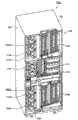
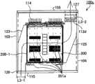
图2A是从前面观察第2实施方式的一例涉及的电子装置的框体的立体图。2A is a perspective view of a housing of an electronic device according to an example of the second embodiment viewed from the front.
图2B是从背面观察第2实施方式的一例涉及的电子装置的框体的立体图。2B is a perspective view of the housing of the electronic device according to the example of the second embodiment viewed from the back.
图2C是从前面观察在第2实施方式的一例涉及的电子装置中安装了多个印刷基板单元的框体的一部分的立体图。FIG. 2C is a perspective view of a part of a housing in which a plurality of printed circuit board units are mounted in an electronic device according to an example of the second embodiment viewed from the front.
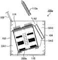
图2D是从前面观察在第2实施方式的一例涉及的电子装置中安装了多个印刷基板单元的框体的内部的一部分的立体图。2D is a perspective view of a part of the inside of a casing in which a plurality of printed circuit board units are mounted in an electronic device according to an example of the second embodiment, viewed from the front.
图3A是第2实施方式的一例涉及的印刷基板单元的立体图。3A is a perspective view of a printed circuit board unit according to an example of the second embodiment.
图3B是第2实施方式的一例涉及的冷却装置的立体图。3B is a perspective view of a cooling device according to an example of the second embodiment.
图3C是第2实施方式的一例涉及的连接基板的立体图。3C is a perspective view of a connection substrate according to an example of the second embodiment.
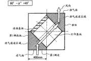
图4是第2实施方式的一例涉及的电子装置的框体的水平方向的剖视图。4 is a cross-sectional view in the horizontal direction of a housing of an electronic device according to an example of the second embodiment.
图5A是表示第2实施方式的一例涉及的电子装置的保养性的图。5A is a diagram showing maintainability of an electronic device according to an example of the second embodiment.
图5B是表示第2实施方式的一例涉及的电子装置的保养性的图。5B is a diagram showing maintainability of the electronic device according to an example of the second embodiment.
图5C是表示第2实施方式的一例涉及的电子装置的保养性的图。5C is a diagram showing maintainability of the electronic device according to an example of the second embodiment.
图5D是表示第2实施方式的一例涉及的电子装置的保养性的图。5D is a diagram showing maintainability of the electronic device according to an example of the second embodiment.
图6A是表示电子装置的框体内的印刷基板的配置例的图。FIG. 6A is a diagram showing an example of arrangement of printed circuit boards in a casing of an electronic device.
图6B是表示电子装置的框体内的印刷基板的配置例的图。FIG. 6B is a diagram showing an example of arrangement of printed circuit boards in the housing of the electronic device.
图6C是表示电子装置的框体内的印刷基板的配置例的图。FIG. 6C is a diagram showing an example of the arrangement of printed circuit boards in the housing of the electronic device.
图6D是表示电子装置的框体内的印刷基板的配置例的图。FIG. 6D is a diagram showing an example of the arrangement of printed circuit boards within the housing of the electronic device.
图7是表示与第2实施方式的一例涉及的电子装置的框体内的印刷基板的配置的变化对应的风量的比率的变化的图。7 is a graph showing changes in the ratio of air volumes corresponding to changes in the arrangement of the printed circuit boards in the casing of the electronic device according to an example of the second embodiment.
图8是表示相对第2实施方式的一例涉及的电子装置的印刷基板的风向的图。FIG. 8 is a diagram showing a wind direction with respect to a printed circuit board of an electronic device according to an example of the second embodiment.
图9是表示在第2实施方式的一例涉及的电子装置的印刷基板上安装的DIMM的温度与风速的关系的图。9 is a graph showing the relationship between the temperature of a DIMM mounted on a printed circuit board of an electronic device according to an example of the second embodiment and the wind speed.
图10A是表示第2实施方式的一例涉及的电子装置的印刷基板上的风速的分布的图。10A is a diagram showing the distribution of wind speeds on the printed circuit board of the electronic device according to an example of the second embodiment.
图10B是表示第2实施方式的一例涉及的电子装置的印刷基板上的温度的分布的图。FIG. 10B is a diagram showing a temperature distribution on a printed circuit board of an electronic device according to an example of the second embodiment.
图11A是表示现有技术涉及的电子装置中的吸排气的概要(之1)的图。11A is a diagram showing an outline (Part 1) of air intake and exhaust in an electronic device according to the conventional art.
图11B是表示现有技术涉及的电子装置中的吸排气的概要(之2)的图。11B is a diagram showing an outline (Part 2) of air intake and exhaust in the electronic device according to the conventional art.
具体实施方式Detailed ways
下面,基于附图详细说明公开技术涉及的电子装置的实施方式的一例。其中,在以下的实施方式的一例中,以电子装置是在框体内配置了至少安装有处理装置以及存储装置的多个系统板(system board)的服务器装置为例进行说明。An example of an embodiment of the electronic device according to the disclosed technology will be described in detail below with reference to the drawings. Among them, in an example of the following embodiments, the electronic device is described as an example in which a plurality of system boards (system boards) on which at least a processing device and a storage device are installed are arranged in a housing.
其中,框体是服务器机架(server rack)。另外,处理装置例如以CPU(Central Processing Unit)、MPU(Micro Processing Unit)、MCU(Micro Control Unit)或者DSP(Digital Signal Processor)等为代表。另外,存储装置例如以包含RAM(Random Access Memory)、ROM(Read Only Memory)等的半导体存储装置为代表。Wherein, the frame body is a server rack (server rack). In addition, the processing device is represented by, for example, CPU (Central Processing Unit), MPU (Micro Processing Unit), MCU (Micro Control Unit), or DSP (Digital Signal Processor). In addition, the storage device is represented by, for example, a semiconductor storage device including RAM (Random Access Memory), ROM (Read Only Memory), and the like.
但是,公开技术可以广泛应用于在框体内配置至少一个安装有作为发热的电子部件的以处理装置、存储装置为代表的集成电路、电源装置或者具备释放出电子部件发出的热的散热片的散热器的至少一个的印刷基板的电子装置。However, the disclosed technology can be widely applied to dispose at least one integrated circuit represented by a processing device and a storage device installed as a heat-generating electronic component in the housing, a power supply device, or a heat sink equipped with a heat sink that releases heat emitted by the electronic component. at least one printed substrate of an electronic device.
另外,公开技术可以应用于例如以交换机、路由器、LAN开关为代表的通信装置等。另外,公开技术也可以应用于安装有主板的个人计算机等。即,公开技术不被以下的实施方式的一例所限定。In addition, the disclosed technology can be applied to, for example, communication devices such as switches, routers, and LAN switches. In addition, the disclosed technology can also be applied to a personal computer or the like on which a motherboard is mounted. That is, the disclosed technology is not limited to an example of the following embodiments.
[第1实施方式的一例][An example of the first embodiment]
图1A是第1实施方式的一例涉及的电子装置的框体的剖视图。另外,图1B是表示图1A的剖视图的电子装置的框体中的垂直方向的位置的图。其中,图1B是第1实施方式的一例涉及的电子装置的框体的主视图。1A is a cross-sectional view of a housing of an electronic device according to an example of the first embodiment. In addition, FIG. 1B is a diagram showing the position in the vertical direction in the casing of the electronic device in the sectional view of FIG. 1A . Among them, FIG. 1B is a front view of a casing of an electronic device according to an example of the first embodiment.
(第1实施方式的一例涉及的框体的构成)(Configuration of the housing according to an example of the first embodiment)
在图1B中,框体100具有顶板101、底板102、第1侧面板103、第2侧面板104、搁板108a和搁板108b。图1B表示将配置在框体100的前面的作为可以开关的门体的后述的前面板115卸下后的状态,省略了前面板115的图示。图1A是图1B中的框体100的A-A剖视图。框体100可以由板金材料形成。或者,也可以由树脂材料形成。In FIG. 1B , the
其中,搁板108a以及搁板108b如后所述,分别包括平行配置的具有相同数目的导轨的2个导板109a1以及109a2。对导板109a1以及109a2而言,底边、上边以及各导轨的水平位置一致,并且导轨按照相对的方式与底板102垂直地配置。Among them, the
而且,通过在相对的多条导轨上配置印刷基板200,在搁板108a以及搁板108b上以层状配置多块印刷基板200。图1B中的框体100的A-A剖视图是使搁板108a中最上层的印刷基板200露出的图。Furthermore, by arranging the printed
其中,由于多块印刷基板200在搁板108a中被以层状配置,所以在图1B中,如果是与A-A平行并且按照能够使印刷基板200露出的方式划分搁板108a的线段,则任意的线段的剖视图都与图1A同样。Among them, since a plurality of printed
如图1A所示,框体100具有:前面板115,其包含具有进气孔118a的进气面118;和背面板105,其包含具有排气孔119a的排气面119,并且与前面板115对置。另外,框体100具有与底板102垂直配置的第1侧面板103、和与第1侧面板103对置的第2侧面板104。As shown in Figure 1A, the
其中,前面板115、背面板105、第1侧面板103以及第2侧面板104与框体100的底板102垂直配置。即,在框体100中,顶板101、底板102、第1侧面板103、第2侧面板104、前面板115以及背面板105按照形成长方体的方式配置。Among them, the
(第1实施方式的一例涉及的印刷基板的配置)(Arrangement of a printed circuit board according to an example of the first embodiment)
在由前面板115、背面板105、第1侧面板103以及第2侧面板104围成的框体100的内部配置有印刷基板200。The printed
印刷基板200包含发热部件201。发热部件201例如是RAM、电源装置等。或者,也可以是具备将发热部件201发出的热释放出的散热片的散热器等放热部件。另外,在框体100的内部配置有与搁板108a所包含的导板109a1以及与导板109a1对置的导板109a2。The printed
另外,在框体100的内部配置有与框体100的底板102垂直配置的连接基板114。另外,在框体100的内部配置有与框体100的底板102垂直配置的冷却装置113。冷却装置113在框体100的内部产生从进气面118所具有的进气孔118a向排气面119所具有的排气孔119a流通的冷却风。冷却装置113例如是轴流式风扇。In addition, a
印刷基板200被配置在导板109a1以及导板109a2相对的导轨上,并且与连接基板114连接。印刷基板200的形状是具有第1侧边200-1以及第2侧边200-2的矩形或者正方形。The printed
对印刷基板200而言,第1侧边200-1被配置在导板109a1的导轨上,第2侧边200-2被配置在导板109a2的导轨上。这样,印刷基板200被配置在搁板108a中。同样地,印刷基板200被配置在搁板108b中。For the printed
印刷基板200按照第1侧边200-1相对第1侧面板103具有第1角度α°(0°<α<90°)的方式配置在搁板108a中。另外,冷却装置113被配置成相对第1侧面板103具有第2角度β(0°≤β≤90°)。The printed
(第1实施方式的一例的效果)(Effect of an example of the first embodiment)
当按照第1侧边200-1相对第1侧面板103具有第1角度α°的方式配置印刷基板200时,与按照平行的方式配置的情况相比,从进气孔118a向排气孔119a流通的冷却风的流路的变化量少。When the printed
即,在按照第1侧边200-1与第1侧面板103平行的方式配置了印刷基板200的情况下,从进气孔118a吸入的冷却风的流路向与第1侧边200-1垂直的方向变化。该情况下流路的变化量为90°。That is, when the printed
另一方面,当按照第1侧边200-1相对第1侧面板103具有第1角度α°的方式配置了印刷基板200时,流路的变化量小于(90°-α°)。因此,可以减少冷却风的流路的变化量,使得从进气孔118a吸入的冷却风有效地向印刷基板200上流通。On the other hand, when the printed
同样,在按照第1侧边200-1与第1侧面板103平行的方式配置了印刷基板200的情况下,当印刷基板200上流通的冷却风被排出到框体100的外部时,该冷却风的流路向与排气面119垂直的方向变化。该情况下流路的变化量包括因冷却装置113引起的流路的变化量为90°。Similarly, when the printed
另一方面,在按照第1侧边200-1相对第1侧面板103具有第1角度α°的方式配置了印刷基板200的情况下,包含因冷却装置113引起的流路的变化量在内,流路的变化量小于(90°-α°)。因此,可以减少冷却风的流路的变化量,使得来自印刷基板200上的冷却风有效地向排气孔119a流通。On the other hand, when the printed
另外,当按照第1侧边200-1相对第1侧面板103具有第1角度α°的方式配置印刷基板200时,与按照平行的方式配置的情况相比,能够更长地获得进气面118以及排气面119的水平方向的长度。即,可以分别在进气面118以及排气面119上设置更多的进气孔118a以及排气孔119a。因此,能够使经由进气孔118a以及排气孔119a被吸入排出的冷却风的量增大,由此提高印刷基板200的发热部件201的冷却效率。In addition, when the printed
另外,当按照第1侧边200-1相对第1侧面板103具有第1角度α°的方式配置印刷基板200时,与平行配置的情况相比,能够较宽地获得排气面119周围的空间。因此,与第1侧边200-1按照和第1侧面板103平行的方式配置的情况相比,能够增设冷却装置113。或者,由于能够拓宽排气面119周围的空间,所以能够配置风量更多的大型冷却装置113或者多个冷却装置113。因此,能够提高对印刷基板200的发热部件201的冷却效率。In addition, when the printed
另外,当按照相对第1侧面板103具有第2角度β的方式配置冷却装置113时,与按照和第1侧面板103平行的方式配置的情况相比,能够较宽地获得与印刷基板200相对的冷却装置113的进气面。因此,由于冷却装置113的吸排气的效率提高,所以可提高对印刷基板200的发热部件201的冷却效率。In addition, when the cooling device 113 is arranged so as to have the second angle β with respect to the
[第2实施方式的一例][An example of the second embodiment]
图2A是从前面观察第2实施方式的一例涉及的电子装置的框体的立体图。另外,图2B是从背面观察第2实施方式的一例涉及的电子装置的框体100a的立体图。其中,在第2实施方式的一例涉及的电子装置的框体100a中,对与第1实施方式的一例涉及的电子装置的框体100相同的构成标注了同样的符号。2A is a perspective view of a housing of an electronic device according to an example of the second embodiment viewed from the front. In addition, FIG. 2B is a perspective view of the
需要说明的是,图2A表示将配置在框体100a的前面的作为可以开关的门体的前面板115卸下后的状态,省略了前面板115的图示。另外,图2B省略了框体100a所具有的背面板105的图示。In addition, FIG. 2A shows the state which removed the
(第2实施方式的一例涉及的框体的构成)(Configuration of the housing according to an example of the second embodiment)
如图2A以及图2B所示,第2实施方式的一例涉及的电子装置的框体100a具有顶板101、底板102、第1侧面板103、第2侧面板104、搁板108a和搁板108b。As shown in FIGS. 2A and 2B , a
底板102被配置成与框体100a的设置面平行。另外,第1侧面板103以及第2侧面板104被配置成与底板102垂直。另外,顶板101被配置成与第1侧面板103以及第2侧面板104垂直。The
另外,框体100a具有未图示的前面板115以及被配置成与前面板115对置的未图示的背面板105。前面板115是被配置成将由顶板101、底板102、第1侧面板103以及第2侧面板104在框体100a的前面形成的矩形的开口部封闭的可以开关的门体。In addition, the
另外,背面板105是按照封闭由顶板101、底板102、第1侧面板103以及第2侧面板104在框体100a的背面形成的矩形的开口部的方式配置的可以开关的门体。In addition, the
(第2实施方式的一例涉及的电子装置的框体的前面立体图)(Front perspective view of housing of electronic device according to an example of the second embodiment)
首先,参照图2A。框体100a在由第1侧面板103以及第2侧面板104划分的空间内具有搁板108a以及搁板108b。在搁板108a以及搁板108b中配置有印刷基板200被配置在刀片(blade)状的框体内的印刷基板单元200a。印刷基板200或者印刷基板单元200a被称作系统板。First, refer to FIG. 2A. The
搁板108a包括平行配置的具有相同数目的导轨的导板109a1以及未图示的导板109a2。搁板108b包括平行配置的具有相同数目的导轨的导板109b1以及导板109b2。The
对导板109a1以及导板109a2而言,导板的底边以及各导轨的水平位置一致,并且,按照导轨相对的方式与底板102垂直配置。另外,导板109b1以及导板109b2与导板109a1以及导板109a2同样地配置。For the guide plate 109a1 and the guide plate 109a2, the bottom edge of the guide plate and the horizontal position of each guide rail are consistent, and are arranged vertically to the
而且,搁板108a以及搁板108b在框体100中按照导板109a1以及导板109b1相对第1侧面板103在水平方向具有第1角度α°(0°<α<90°)的方式配置。而且,通过在相对的多条导轨上配置后述的印刷基板单元200a,能够在搁板108a以及搁板108b中以层状配置多个印刷基板单元200a。结果,多个印刷基板单元200a被配置成相对第1侧面板103在水平方向上具有第1角度α°(0°<α<90°)。Furthermore,
另外,在框体100a的前面由搁板108a以及第1侧面板103划分的空间中设置有进气通道开口部106a。同样,在框体100a的前面由搁板108b以及第1侧面板103划分的空间中设置有进气通道开口部106b。In addition, an air
另外,在框体100a的垂直方向,在搁板108a以及搁板108b之间排列配置有电源装置110以及搁板111。电源装置110被配置在第1侧面板103侧,搁板111被配置在第2侧面板104侧。In addition, a
电源装置110对在框体100a内配置了安装有电子部件的多个印刷基板的电子装置控制电源供给。搁板111中配置有在刀片状的框体内配置了作为电子装置与外部装置进行数据的发送接收的连接接口的印刷基板的多个接口单元。连接接口或者接口单元被称为IO(Input Output)系统板。The
搁板111包括平行配置的具有相同数目的导轨的导板112a以及未图示的导板112b。对导板112a以及导板112b而言,导板的底边以及各导轨的水平位置一致,并且导轨按照相对的方式与底板102垂直配置。The
而且,通过在导板112a以及导板112b的相对的多条导轨上配置接口单元,可以在搁板111中以层状配置多个接口单元。Furthermore, by arranging the interface units on the plurality of opposing rails of the
(第2实施方式的一例涉及的电子装置的框体的背面立体图)(A rear perspective view of a casing of an electronic device according to an example of the second embodiment)
接下来,参照图2B。在框体100a中,在搁板108a的背面配置有被称为背板(back panel)的连接基板114a。连接基板114a按照与导板109a1以及导板109a2垂直的方式配置。另外,连接基板114a在搁板108a的背面按照将包括导板109a1以及导板109a2而形成的矩形的开口部封闭的方式配置。Next, refer to FIG. 2B. In the
连接基板114a将在搁板108a中配置的多个印刷基板单元200a分别具有的印刷基板200电连接。通过在多个印刷基板单元200a的框体的背面设置的印刷基板200的连接端子与连接基板114a连接,使得多个印刷基板单元200a电连接。The
其中,由于印刷基板200按照第1侧边200-1相对第1侧面板103在水平方向上具有α°的角度的方式配置,所以连接基板114a被配置成相对第1侧面板103在水平方向上具有90°+α°的角度。Wherein, since the printed
在框体100a的背面,在由第2侧面板104以及导板109a2划分的空间中设置有排气通道开口部107a。在框体100a内,在第2侧面板104以及导板109a2之间产生的空间配置有冷却装置113a。冷却装置113a通过纵横排列同样构成的多个风扇而形成。风扇是轴流式风扇。冷却装置113a被配置成相对第1侧面板103具有第2角度β°(0°≤β≤90°)。On the back surface of the
同样,在框体100a中,在搁板108b的背面配置有被称为背板的连接基板114b。连接基板114b按照与导板109b1以及导板109b2垂直的方式配置。另外,在搁板108a的背面,连接基板114b被配置成将包括导板109b1以及导板109b2而形成的矩形的开口部封闭。Similarly, in the
连接基板114b与连接基板114a同样地将在搁板108b中配置的多个印刷基板单元200a分别具有的印刷基板200电连接。与连接基板114a同样,连接基板114b被配置成相对第1侧面板103在水平方向上具有90°+α°的角度。Like the
在框体100a的背面,在由第2侧面板104以及导板109b2划分的空间中设置有排气通道开口部107b。在框体100a内,在第2侧面板104以及导板109b2之间产生的空间中配置有冷却装置113b。与冷却装置113a同样,冷却装置113b通过纵横排列同样构成的多个风扇而形成。冷却装置113b被配置成相对第1侧面板103具有第2角度β°(0°≤β≤90°)。On the back surface of the
此外,在框体100a中,在搁板111的背面排列配置有冷却装置116以及连接基板117。冷却装置116对配置于搁板111的多个接口单元的在框体内配置的印刷基板上安装的电子部件进行冷却。另外,连接基板117是将配置在搁板111中的多个接口单元的配置在框体内的印刷基板电连接的背板。另外,电源装置110被配置在连接基板117以及第1侧面板103之间。In addition, in the
图2C是从前面观察第2实施方式的一例涉及的电子装置中安装了多个印刷基板单元的框体的一部分的立体图。如图2C所示,在由顶板101、第1侧面板103以及第2侧面板104形成的空间内配置的搁板108a中配置有多个印刷基板单元200a。在搁板108a中,多个印刷基板单元200a被配置成各印刷基板单元200a的前面对齐在同一面上。其中,在搁板108b中也与搁板108a同样。2C is a perspective view of a part of the housing in which a plurality of printed circuit board units are mounted in the electronic device according to the example of the second embodiment viewed from the front. As shown in FIG. 2C , a plurality of printed
图2D是从前面观察第2实施方式的一例涉及的电子装置中安装有多个印刷基板单元的框体的内部的一部分的立体图。图2D表示从图2C将顶板101以及在搁板108a的最上层配置的印刷基板单元200a的框体的顶板拆下后的状态。2D is a perspective view of a part of the inside of the housing in which the plurality of printed circuit board units are mounted in the electronic device according to the example of the second embodiment viewed from the front. FIG. 2D shows a state in which the
如图2D所示,配置在搁板108a中的多个印刷基板单元200a按照第1侧边200-1相对第1侧面板103在水平方向上具有角度的方式配置,并和连接基板114a连接。由第1侧面板103以及搁板108a的导板109a1划分的空间是进气通道区域DA1。在进气通道区域DA1的框体100a的前面部分设置有进气通道开口部106a。As shown in FIG. 2D , a plurality of printed
另外,图2D所示的冷却装置113a在由搁板108a以及第2侧面板104划分的空间中按照相对第1侧面板103在水平方向上具有β°的角度的方式配置。由搁板108a、搁板108a的导板109a2以及冷却装置113a划分的空间是中间通道区域DA2。另外,由图2D所示的冷却装置113a以及第2侧面板104划分的空间是排气通道区域DA3。在排气通道区域DA3的框体100a的背面部分设置有排气通道开口部107a。其中,将进气通道区域DA1、中间通道区域DA2以及排气通道区域DA3总称为冷却用通道。In addition, the
另外,作为发热的电子部件,印刷基板200安装有DIMM(DualInline Memory Module)201a。DIMM是RAM模块的一种,通过高集成度的半导体存储元件双面安装在矩形的板状基板而形成。DIMM201a按照DIMM201a的基板与印刷基板200的第1侧边200-1垂直的方式被配置于印刷基板200。In addition, a DIMM (Dual Inline Memory Module) 201a is mounted on the printed
在图2D中,通过冷却装置113a动作而从进气通道开口部106a吸入到框体100a的内部的冷却风在进气通道区域DA1中流通的方向向印刷基板200的方向改变。然后,向印刷基板200改变了流通的方向的冷却风对DIMM201a进行冷却,在印刷基板200上通过。In FIG. 2D , the direction in which the cooling air sucked into the
在印刷基板200上通过的冷却风在中间通道区域DA2中流通的方向向冷却装置113a的方向改变。然后,流通的方向向冷却装置113a改变了的冷却风在通过了冷却装置113a后,经由排气通道区域DA3被从排气通道开口部107a向框体100a的外部排出。The direction in which the cooling air passing over the printed
(第2实施方式的一例涉及的印刷基板单元)(Printed circuit board unit according to an example of the second embodiment)
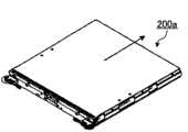
图3A是第2实施方式的一例涉及的印刷基板单元的立体图。第2实施方式的一例涉及的印刷基板单元200a是在长方体的框体内配置了印刷基板200的刀片体。印刷基板单元200a沿图3A所示的箭头的方向收纳于搁板108a以及搁板108b,与连接基板114a以及114b连接。3A is a perspective view of a printed circuit board unit according to an example of the second embodiment. A printed
(第2实施方式的一例涉及的冷却装置)(Cooling device according to an example of the second embodiment)
图3B是第2实施方式的一例涉及的冷却装置的立体图。第2实施方式的一例涉及的冷却装置113a以及113b在矩形或者正方形的框架体113-1内配置有至少1个风扇113-2。风扇113-2具有通过内置的马达的动力而旋转的旋转轴113-3、以及旋转自如地安装在旋转轴113-3上的叶片部113-4。冷却装置113a以及113b通过叶片部113-4进行旋转而吸入、排出冷却风。3B is a perspective view of a cooling device according to an example of the second embodiment. In the
(第2实施方式的一例涉及的连接基板)(Connection board according to an example of the second embodiment)
图3C是第2实施方式的一例涉及的连接基板的立体图。对于第2实施方式的一例涉及的连接基板114a以及114b而言,在矩形或者正方形的框架体114-1的面中的连接印刷基板200的面上配置有多个连接部114-2。沿着图3C中图示的箭头的方向,一个印刷基板200的连接端子与一个连接部114-2连接。因此,连接基板114a以及114b连接多个印刷基板200。3C is a perspective view of a connection substrate according to an example of the second embodiment. In the
图4是第2实施方式的一例涉及的电子装置的框体的水平方向的剖视图。图4是图1B中的A-A或者与A-A平行并且按照能够使印刷基板200露出的方式划分搁板108a的线段中的框体100a的剖视图。其中,与图1B中的A-A平行并且按照能够使印刷基板200露出的方式划分搁板108b的线段中的框体100a的剖视图也同样。4 is a cross-sectional view in the horizontal direction of a housing of an electronic device according to an example of the second embodiment. FIG. 4 is a cross-sectional view of
(第2实施方式的一例涉及的印刷基板的配置)(Arrangement of a printed circuit board according to an example of the second embodiment)
如图4所示,框体100a具有:前面板115,其包含具有进气孔118a的进气面118;和背面板105,其包含具有排气孔119a的排气面119,并且与前面板115对置。而且,框体100a具有与底板102垂直配置的第1侧面板103、和与第1侧面板103对置的第2侧面板104。As shown in Figure 4, the
在由前面板115、背面板105、第1侧面板103以及第2侧面板104围成的框体100a的内部配置有印刷基板单元200a,该印刷基板单元200a收纳了配置有DIMM201a的印刷基板200。DIMM201a按照DIMM201a的基板与第1侧边200-1以及第2侧边200-2垂直的方式配置。在印刷基板200的框体100a的内部,配置有搁板108a所包含的导板109a1以及与导板109a1对置的导板109a2。Inside the
另外,在框体100a的内部配置有与框体100a的底板102垂直配置的连接基板114a。而且,在框体100a的内部配置有与框体100的底板102垂直配置的冷却装置113a。冷却装置113a在框体100a的内部产生从进气面118所具有的进气孔118a向排气面119所具有的排气孔119a流通的冷却风。In addition, a
其中,通过DIMM201a按照DIMM201a的基板与第1侧边200-1以及第2侧边200-2垂直的方式配置,使得冷却装置113a吸入的进气在印刷基板200所具有的前边200-3与后边200-4之间流通。Wherein, the
印刷基板单元200a配置在导板109a1以及导板109a2的相对的导轨上,并且与连接基板114a连接。其中,印刷基板单元200a按照印刷基板200的第1侧边200-1相对第1侧面板103具有第1角度α°(0°<α<90°)的方式配置。而且,冷却装置113a按照相对第1侧面板103具有第2角度β(0°≤β≤90°)的方式配置。The printed
当按照第1侧边200-1相对第1侧面板103具有第1角度α°的方式配置印刷基板200时,进气面118以及排气面119的水平方向的长度分别为“L1-1”、“L1-2″。When the printed
需要说明的是,当按照相对第1侧面板103具有第2角度β(α°≤β<90°)的方式在框体100a内配置冷却装置113a时,与β<α°或者β=90°的情况相比较,能够采用更大型或者更多重化的冷却装置。其原因在于,当忽视冷却装置113a的厚度来进行简单计算时,与“L1-2”相比较,能够配置的冷却装置的最大宽度变大为“(L1-2)/sinβ”。It should be noted that when the
如图4所示,对经由进气孔118a而吸入的冷却风而言,流路经由由第1侧面板103、通道壁120以及121划分的进气通道区域DA1向印刷基板200侧变化。As shown in FIG. 4 , the flow path of the cooling air sucked in through the
然后,流路向印刷基板200侧变化了的冷却风在印刷基板200上通过,并且被冷却装置113a施力,其流路经由由通道壁122划分的中间通道区域DA2而向冷却装置113a侧变化。Then, the cooling air whose flow path has been changed to the printed
然后,流路向冷却装置113a侧变化了的冷却风经由由冷却装置113a、第2侧面板104以及通道壁122划分的排气通道区域DA3,通过排气孔119a向外部排出。Then, the cooling air whose flow path has changed toward the side of the
(电子装置的保养性)(maintenance of electronic devices)
图5A~图5D是表示第2实施方式的一例涉及的电子装置的保养性的图。第2实施方式的一例涉及的电子装置的框体100a内配置的印刷基板单元200a、冷却装置113a以及连接基板114a在卸下了前面板115或者背面板105的状态下,可以为了进行维护而被取出。5A to 5D are diagrams showing maintainability of the electronic device according to an example of the second embodiment. The printed
如图5A以及图5B所示,通过在卸下了前面板115的状态下使印刷基板单元200a向箭头A1的方向移动,可以解除其与连接基板114a的连接,将其从搁板108a以及框体100a中取出。As shown in FIG. 5A and FIG. 5B, by moving the printed
另外,如图5A以及图5C所示,通过在卸下了背面板105的状态下使冷却装置113a向箭头A2的方向移动,可以将其从框体100a中取出。另外,如图5A以及图5D所示,在卸下了背面板105并向箭头A1的方向移动了印刷基板单元200a的状态下,通过使连接基板114a向沿着箭头A3的方向移动,可以将其从框体100a中取出。In addition, as shown in FIGS. 5A and 5C ,
其中,连接基板114a具有与第1侧面板103在框体100a的内面侧所具有的销128嵌合的嵌合孔129。连接基板114a在与第1侧面板103邻接的框架体114-1的部分上具有嵌合孔129。连接基板114a通过销128以及嵌合孔129的嵌合被固定于第1侧面板103。Among them, the
当从框体100a中取出连接基板114a时,首先解除销128与嵌合孔129的嵌合,然后使连接基板114a移动。因此,如箭头A3所示,使连接基板114a移动的方向在移动中途发生变化。When taking out the
如参照图5A~图5D说明那样,第2实施方式的一例涉及的电子装置的框体100a内配置的印刷基板单元200a、冷却装置113a以及连接基板114a可容易地向框体100a的外部取出来进行维护。As described with reference to FIGS. 5A to 5D , the printed
(与印刷基板的配置的角度对应的风量)(Air volume corresponding to the angle of arrangement of the printed circuit board)
图6A~图6D是表示电子装置的框体内的印刷基板的配置例的图。即,表示印刷基板按照相对电子装置的第1侧面板具有α°的角度的方式配置的配置例。其中,进气通道的进气面的宽度以800mm为例。另外,第1侧边的长度以500mm为例。6A to 6D are diagrams showing an example of arrangement of printed circuit boards in the casing of the electronic device. That is, an arrangement example is shown in which the printed circuit board is arranged so as to form an angle of α° with respect to the first side panel of the electronic device. Wherein, the width of the air intake surface of the air intake channel is 800 mm as an example. In addition, the length of the first side is 500 mm as an example.
图6A表示α=90°、即从进气通道向排气通道吸排气的冷却风的风向为(90°-α°)=0°的情况。该情况下,印刷基板按照第1侧边相对第1侧面板具有90°的角度的方式配置。FIG. 6A shows the case where α=90°, that is, the wind direction of the cooling air sucked and exhausted from the intake passage to the exhaust passage is (90°-α°)=0°. In this case, the printed circuit board is arranged such that the first side has an angle of 90° with respect to the first side panel.
如图6A所示,对从进气面吸入的冷却风而言,流路不会被遮蔽物、例如连接基板遮挡。另外,能够将进气面确保到框体的宽度的最大长度。因此,可吸入较多冷却风,并且不使吸入的冷却风的流路变化地使其有效地在印刷基板上流通。即,印刷基板相对第1侧面板具有90°的角度的配置是能够有效地冷却电子部件的配置。As shown in FIG. 6A , for the cooling air sucked in from the air intake surface, the flow path is not blocked by a shield such as a connecting substrate. In addition, the intake surface can be secured up to the maximum length of the width of the housing. Therefore, a large amount of cooling air can be sucked in, and the flow path of the sucked cooling air can be efficiently circulated on the printed circuit board without changing the flow path. That is, the arrangement in which the printed circuit board forms an angle of 90° with respect to the first side panel is an arrangement in which electronic components can be effectively cooled.
但是,在图6A所示的印刷基板的配置中,印刷基板以及连接基板的连接方向相对前面板具有90°的角度。因此,即使卸下与进气面形成同一面的框体的前面板,也不容易解除印刷基板以及连接基板的连接来向框体的外部取出印刷基板。However, in the arrangement of the printed board shown in FIG. 6A , the connection direction of the printed board and the connection board has an angle of 90° with respect to the front panel. Therefore, even if the front panel of the housing that forms the same surface as the intake surface is removed, it is not easy to release the connection of the printed circuit board and the connection board to take out the printed circuit board to the outside of the housing.
鉴于此,如图6B所示,按照α=45°、即从进气通道向排气通道吸排气的冷却风的风向具有(90°-α°)=45°的角度的方式配置印刷基板。该情况下,印刷基板按照第1侧边相对第1侧面板具有45°的角度的方式配置。In view of this, as shown in FIG. 6B, the printed circuit board is arranged in such a way that α=45°, that is, the wind direction of the cooling air sucked and exhausted from the intake passage to the exhaust passage has an angle of (90°-α°)=45°. . In this case, the printed circuit board is arranged such that the first side has an angle of 45° with respect to the first side panel.
如图6B所示,为了使从进气面吸入的冷却风从排气面排出,与α=90°的情况相比,要求使流路变化。另外,进气面以及排气面的宽度变为400mm。因此,与图6A所示的α=90°的印刷基板的配置相比较,从吸入面吸入的冷却风的量小,并且吸入的冷却风在印刷基板上流通时的效率性差。As shown in FIG. 6B , in order to discharge the cooling air taken in from the intake surface from the discharge surface, it is required to change the flow path compared to the case of α=90°. In addition, the width of the intake surface and the exhaust surface is changed to 400 mm. Therefore, compared with the arrangement of printed circuit boards with α=90° shown in FIG. 6A , the amount of cooling air sucked in from the suction surface is small, and the efficiency of the sucked cooling air flowing on the printed circuit boards is poor.
但在图6B所示的印刷基板的配置中,印刷基板以及连接基板的连接方向相对前面板具有45°的角度。因此,与图6A所示的印刷基板的配置相比,将与进气面形成同一面的框体的前面板卸下,解除印刷基板以及连接基板的连接,向框体的外部取出印刷基板变得容易。However, in the arrangement of the printed circuit board shown in FIG. 6B , the connecting direction of the printed circuit board and the connection substrate has an angle of 45° with respect to the front panel. Therefore, compared with the arrangement of the printed circuit board shown in FIG. 6A , the front panel of the frame that forms the same surface as the intake surface is removed, the connection of the printed circuit board and the connection circuit board is released, and the printed circuit board is taken out of the frame. easy.
进而,如图6C所示,按照α=15°、即从进气通道向排气通道吸排气的冷却风的风向具有(90°-α°)=75°的角度的方式配置印刷基板。该情况下,印刷基板按照第1侧边相对第1侧面板具有15°的角度的方式配置。Furthermore, as shown in FIG. 6C , the printed circuit board is arranged such that α=15°, that is, the air direction of the cooling air sucked and exhausted from the intake duct to the exhaust duct has an angle of (90°−α°)=75°. In this case, the printed circuit board is arranged such that the first side has an angle of 15° with respect to the first side panel.
如图6C所示,为了使由进气面吸入的冷却风从排气面排出,与α=45°的情况相比要求进一步使流路变化。另外,进气面以及排气面的宽度变为250mm。因此,与图6B所示的印刷基板的配置相比较,从吸入面吸入的冷却风的量小,并且吸入的冷却风在印刷基板上流通时的效率性更差。As shown in FIG. 6C , in order to discharge the cooling air taken in from the intake surface from the discharge surface, it is required to further change the flow path compared to the case of α=45°. In addition, the width of the intake surface and the exhaust surface is changed to 250 mm. Therefore, compared with the arrangement of the printed circuit board shown in FIG. 6B , the amount of cooling air sucked from the suction surface is small, and the efficiency of the sucked cooling air flowing on the printed circuit board is lower.
但是,在图6C所示的印刷基板的配置中,印刷基板以及连接基板的连接方向相对前面板具有15°的角度。因此,与图6B所示的印刷基板的配置相比,将与进气面形成同一面的框体的前面板卸下,解除印刷基板以及连接基板的连接并向框体的外部取出印刷基板变得更容易。However, in the arrangement of the printed board shown in FIG. 6C , the connection direction of the printed board and the connection board has an angle of 15° with respect to the front panel. Therefore, compared with the arrangement of the printed circuit board shown in FIG. 6B , the front panel of the frame that forms the same surface as the intake surface is removed, the connection of the printed circuit board and the connection circuit board is released, and the printed circuit board is taken out of the frame. easier.
进而,如图6D所示,按照α=0°、即从进气通道向排气通道吸排气的冷却风的流路具有(90°-α°)=90°的角度的方式配置印刷基板。该情况下,印刷基板按照第1侧边相对第1侧面板具有90°的角度的方式配置。Furthermore, as shown in FIG. 6D, the printed circuit board is arranged in such a way that α=0°, that is, the flow path of the cooling air sucked and exhausted from the intake passage to the exhaust passage has an angle of (90°-α°)=90°. . In this case, the printed circuit board is arranged such that the first side has an angle of 90° with respect to the first side panel.
在图6D所示的印刷基板的配置中,印刷基板以及连接基板的连接方向相对前面板具有0°的角度。因此,与图6C所示的印刷基板的配置相比,将与进气面形成同一面的框体的前面板卸下,解除印刷基板以及连接基板的连接来向框体的外部取出印刷基板变得更容易。In the configuration of the printed board shown in FIG. 6D , the connection direction of the printed board and the connection board has an angle of 0° with respect to the front panel. Therefore, compared with the arrangement of the printed circuit board shown in FIG. 6C , the front panel of the frame that forms the same surface as the air intake surface is removed, the connection of the printed circuit board and the connection circuit board is released, and the printed circuit board is taken out of the frame. easier.
但是,如图6D所示,为了使由进气面吸入的冷却风从排气面排出,与α=15°的情况相比,要求进一步使流路变化。另外,进气面以及排气面的宽度变为150mm。因此,与图6C所示的印刷基板的配置相比,从吸入面吸入的冷却风的量更小,并且吸入的冷却风在印刷基板上流通时的效率性更差。However, as shown in FIG. 6D , in order to discharge the cooling air taken in from the intake surface from the discharge surface, it is required to further change the flow path compared to the case of α=15°. In addition, the width of the intake surface and the exhaust surface becomes 150 mm. Therefore, compared with the arrangement of the printed circuit board shown in FIG. 6C , the amount of cooling air sucked from the suction surface is smaller, and the efficiency of the sucked cooling air flowing on the printed circuit board is lower.
上述的α°以及风量的关系如图7所示。图7是表示与第2实施方式的一例涉及的电子装置的框体内的印刷基板的配置的变化对应的风量的比率的变化的图。“风量的比率”是在框体100a中使α°变化时的风量相对(90°-α°)=0°时吸排气的风量的比率。The relationship between the aforementioned α° and the air volume is shown in FIG. 7 . 7 is a graph showing changes in the ratio of air volumes corresponding to changes in the arrangement of the printed circuit boards in the casing of the electronic device according to an example of the second embodiment. The "ratio of air volume" is the ratio of the air volume when α° is changed in the
在图7中,表示了取(90°-α°)为横轴、取风量的比率为纵轴的曲线g1以及g2。曲线g1表示在将(90°-α°)=0°时的风量设为“1”的情况下,使配置印刷基板的第1角度α°变化时的风量的比率。另外,曲线g2表示在将(90°-α°)=0°时的风量设为“1”的情况下,对使配置印刷基板的第1角度α°变化时的风量上加上与进气面的宽度的变化对应的风量后的风量的比率。In FIG. 7 , curves g1 and g2 are shown with (90°-α°) as the horizontal axis and the ratio of the intake air volume as the vertical axis. The curve g1 represents the ratio of the air volume when the first angle α° at which the printed circuit board is disposed is changed when the air volume at (90°−α°)=0° is set to “1”. In addition, the curve g2 shows that when the air volume when (90°-α°)=0° is set to "1", the air volume when the first angle α° at which the printed circuit board is arranged is changed by adding and intake air. The ratio of the air volume to the air volume after the change in the width of the face.
如图7所示,使印刷基板的配置变化为α=90°(90°-α°=0°)、45°(90°-α°=45°)、15°(90°-α°=75°)、0°(90°-α°=90°)。这时,曲线g1分别取0.75、0.5、0.25的值。即,风量的比率对应(90°-α°)单调减少。As shown in FIG. 7, the layout of the printed circuit board is changed to α=90° (90°-α°=0°), 45° (90°-α°=45°), 15° (90°-α°= 75°), 0° (90°-α°=90°). At this time, the curve g1 takes values of 0.75, 0.5, and 0.25, respectively. That is, the ratio of the air volume decreases monotonously corresponding to (90°-α°).
并且,曲线g2分别取3.25以上小于3.5的规定值、2、0.75以上小于1的规定值。即,风量对应(90°-α°)单调减少。即,风量的比率对应进气面的幅以及(90°-α°)单调减少。In addition, the curve g2 takes a predetermined value of 3.25 to less than 3.5, 2, and a predetermined value of 0.75 to less than 1, respectively. That is, the air volume decreases monotonously corresponding to (90°-α°). That is, the ratio of the air volume decreases monotonously with respect to the width of the intake surface and (90°-α°).
但是,如上所述,将印刷基板以及连接基板的连接解除来向框体的外部取出印刷基板这一印刷基板的维护性随着(90°-α°)的增加而提高。因此,风量以及印刷基板的维护性存在折衷(tradeoff)的关系。因此,(90°-α°)、即α能够根据风量以及印刷基板的维护性的平衡要求,设定为比0°大且小于90°的值。However, as described above, the maintainability of the printed circuit board by releasing the connection of the printed circuit board and the connection board to take out the printed circuit board to the outside of the housing improves as (90°-α°) increases. Therefore, there is a trade-off relationship between the air volume and the maintainability of the printed circuit board. Therefore, (90°−α°), that is, α can be set to a value larger than 0° and smaller than 90° according to the balance between the air volume and the maintainability of the printed circuit board.
(DIMM的冷却)(DIMM cooling)
图8是表示针对第2实施方式的一例涉及的电子装置的印刷基板的风向的图。如图8所示,按照与安装在印刷基板200上的DIMM201a-1以及201a-2的基板的配置方向垂直或者大致垂直的方式使冷却风在印刷基板200上流通。FIG. 8 is a diagram showing a wind direction for a printed circuit board of an electronic device according to an example of the second embodiment. As shown in FIG. 8 , the cooling air flows on the printed
这里,通常当对安装于印刷基板200的DIMM201a-1以及201a-2进行气冷时,随着冷却风的风量的增加,由DIMM201a-1以及201a-2针对冷却风的阻力引起的冷却风的压力损耗增加。另一方面,随着冷却风的风量的增加,冷却装置113a的静压也降低。其中,静压是指与冷却风的流路垂直配置的冷却装置113a针对冷却风的垂直面上起作用的压力。因此,要求以冷却装置113a的静压强过针对冷却风的由DIMM201a-1以及201a-2引起的冷却风的压力损耗的方式设定冷却风的风量。Here, in general, when the
图9是表示安装于第2实施方式的一例涉及的电子装置的印刷基板上的DIMM的温度与风速的关系的图。即,图9分别用曲线g3以及曲线g4表示了当如图8所示那样在印刷基板200上使冷却风流通时与冷却风的风速对应的配置在前列以及后列的DIMM的温度的变化。9 is a graph showing the relationship between the temperature of a DIMM mounted on a printed circuit board of an electronic device according to an example of the second embodiment and the wind speed. That is, FIG. 9 shows changes in temperature of DIMMs arranged in the front row and rear row according to the wind speed of the cooling air when the cooling air is passed through the printed
这里,“前列的DIMM”是DIMM201a-1,“后列的DIMM”是DIMM201a-2。另外,图9中用曲线g5表示了与冷却风的风速对应的DIMM201a-1以及DIMM201a-2的温度差ΔT的变化。这里,“冷却风的风速”是在图8中当在印刷基板200上流通的冷却风通过印刷基板200的第1侧边200-1时的风速。将该风速称为“前面风速”。Here, the "DIMM in the front row" is DIMM201a-1, and the "DIMM in the rear row" is DIMM201a-2. In addition, in FIG. 9, the change of the temperature difference ΔT between DIMM201a-1 and DIMM201a-2 according to the wind speed of cooling air is shown by curve g5. Here, the "wind speed of the cooling wind" is the wind speed when the cooling wind flowing on the printed
需要说明的是,在图9中,取风速[m/s]为横轴,取DIMM温度[℃]为左纵轴,取ΔT[℃]为右纵轴。另外,DIMM201a-1以及201a-1以消耗电力为10.22W的DIMM为例。而且,在图9中,表示10.22W的DIMM的温度的上限的阈值“Tcase”以“85[℃]”为例。It should be noted that in FIG. 9 , wind speed [m/s] is taken as the horizontal axis, DIMM temperature [° C.] is taken as the left vertical axis, and ΔT [° C.] is taken as the right vertical axis. In addition, DIMMs 201a-1 and 201a-1 are DIMMs with a power consumption of 10.22W as an example. In addition, in FIG. 9 , the threshold "Tcase" indicating the upper limit of the temperature of the 10.22W DIMM is "85 [°C]" as an example.
如图9的曲线g3所示,DIMM201a-1的温度相对于风速单调减少。即,表示风速越快,DIMM201a-1的温度越降低。这意味着通过冷却风在印刷基板200上更快地流通,DIMM20a-1被更有效地冷却。As shown by the curve g3 in FIG. 9 , the temperature of the
另外,如图9的曲线g4所示那样,DIMM201a-2的温度也与DIMM201a-1的温度同样,相对于风速单调减少。即,表示风速越快,DIMM201a-2的温度越降低。In addition, as shown in the graph g4 of FIG. 9 , the temperature of
另外,如图9的曲线g5所示,从DIMM201a-2的温度中减去了DIMM201a-1的温度的ΔT也同样相对于风速单调减少。即,表示风速越快,DIMM201a-1与201a-2的温度差越缩小。Also, as shown in the graph g5 of FIG. 9 , ΔT obtained by subtracting the temperature of
这里,DIMM201a-2的温度大体上高于DIMM201a-1的温度。其原因如后所述,由于对DIMM201a-2进行冷却的冷却风与前面风速相比风速降低(参照图10A)以及基于DIMM201a-1的冷却温度已经上升(参照图10B)。Here, the temperature of DIMM201a-2 is substantially higher than the temperature of DIMM201a-1. The reason for this is that the cooling air cooling DIMM201a-2 has a lower wind speed than the previous wind speed (see FIG. 10A ) and the cooling temperature of DIMM201a-1 has increased (see FIG. 10B ), as will be described later.
图10A是表示第2实施方式的一例涉及的电子装置的印刷基板上的风速的分布的图。图10A表示前面风速为“3[m/s]”的情况。如图10A所示,对DIMM201a-2进行冷却的冷却风的风速与前面风速以及对DIMM201a-1进行冷却的冷却风的风速相比速度降低。10A is a diagram showing the distribution of wind speeds on the printed circuit board of the electronic device according to an example of the second embodiment. FIG. 10A shows a case where the front wind speed is "3 [m/s]". As shown in FIG. 10A , the wind speed of the cooling air cooling the
图10B是表示第2实施方式的一例涉及的电子装置的印刷基板上的温度的分布的图。图10B表示前面风速为“3[m/s]”的情况。如图10B所示,对DIMM201a-2进行冷却的冷却风的温度与前面风速以及对DIMM201a-1进行冷却的冷却风的温度相比温度上升。FIG. 10B is a diagram showing a temperature distribution on a printed circuit board of an electronic device according to an example of the second embodiment. FIG. 10B shows a case where the front wind speed is "3 [m/s]". As shown in FIG. 10B , the temperature of the cooling air cooling the
(现有技术的问题点)(problems of prior art)
图11A是表示现有技术涉及的电子装置中的吸排气的概要(之1)的图。在现有技术涉及的电子装置的框体100b中,相对第1侧边200-1在水平方向上以0°的角度配置印刷基板200。另外,按照DIMM201a的基板与印刷基板200的第1侧边200-1平行的方式在印刷基板200上配置在矩形的板状基板上双面安装了半导体存储元件的DIMM201a。11A is a diagram showing an outline (Part 1) of air intake and exhaust in an electronic device according to the conventional art. In the housing 100b of the conventional electronic device, the printed
另外,冷却装置113c在框体100b内被配置在前面板115以及印刷基板200之间。通过冷却装置113c从设置在框体100a的前面板115的进气孔吸入的冷却风对DIMM201a进行冷却,并在印刷基板200上通过。然后,在印刷基板200上通过了的冷却风经由最小宽度为“L2”的通道以及连接基板114所具有的孔,从设置在背面板105上的排气孔排出到外部。In addition, the cooling device 113c is arranged between the
这里,在最小宽度为“L2”的通道以及连接基板114所具有的孔中,冷却风的流通量存有界限。即,关于印刷基板200上的冷却风的流通,通道以及连接基板114成为瓶颈。因此,对图11A所示的现有技术涉及的电子装置中的吸排气而言,从设置在背面板105上的排气孔向外部排出由进气孔吸入的冷却风的效率性低。而且,安装在印刷基板200上的DIMM201a的冷却效率低。Here, there is a limit to the flow rate of the cooling air in the passage with the minimum width "L2" and the hole of the connecting
图11B是表示现有技术涉及的电子装置中的吸排气的概要(之2)的图。为了避免参照图11A在上面叙述的、关于印刷基板200上的冷却风通道以及连接基板114流通成为瓶颈的情况,如图11B所示那样配置印刷基板200以及DIMM201a。11B is a diagram showing an outline (Part 2) of air intake and exhaust in the electronic device according to the conventional art. In order to avoid the bottleneck of the cooling air passage on the printed
即,在电子装置的框体100c中,相对第1侧边200-1在水平方向上以0°的角度配置印刷基板200。另外,按照DIMM201a的基板与印刷基板200的第1侧边200-1垂直的方式在印刷基板200上配置在矩形的板状基板上双面安装了半导体存储元件的DIMM201a。That is, in the
另外,在框体100c内,基于由通道壁123、124以及第1侧面板103实现的划分,设置进气通道区域。而且,在框体100c内,基于由通道壁125、第2侧面板104以及冷却装置113d实现的划分,设置排气通道区域。其中,冷却装置113d与背面板105平行配置。In addition, in the
另外,在前面板115上设置有与第1侧面板103以及通道壁124的最短距离、即“L3-1”相当的宽度的进气面126。另外,在背面板105上设置有与和冷却风的流路垂直或者大致垂直配置的冷却装置113d的最大宽度、即“L3-2”相当的宽度的排气面127。In addition, the
如图11B所示,当在框体100c内配置印刷基板200,形成吸排气的流路时,如图中的箭头所示那样,吸入到框体100c内的冷却风在被排出到框体100c外之前流路的方向大幅变化。As shown in FIG. 11B , when the printed
另外,进气面126的宽度“L3-1”比图4所示的进气面118的宽度“L1-1”窄。同样,排气面127的宽度“L3-2”比图4所示的排气面119的宽度“L1-2”窄。即,从吸入面吸入的冷却风的量小且吸入的冷却风在印刷基板上流通时的效率性低。In addition, the width " L3 - 1 " of the
近些年,图11B所示那样的现有技术对于安装在印刷基板上的电子部件的性能提高引起的发热量的增大,冷却性能不足。当为了消除冷却性能不足而进行冷却装置的增加、吸排气的通道区域的增强时,会产生框体尺寸扩大的问题。In recent years, the prior art as shown in FIG. 11B has insufficient cooling performance against an increase in heat generation due to performance improvement of electronic components mounted on a printed circuit board. In order to eliminate the lack of cooling performance, increasing the number of cooling devices and strengthening the passage area for intake and exhaust will cause a problem of enlarging the size of the housing.
(第2实施方式的一例的效果)(Effect of an example of the second embodiment)
第2实施方式的一例涉及的电子装置能够消除上述那样的现有技术的问题,能够不扩大框体尺寸地扩大进气面、进气通道区域、排气面以及排气通道区域,增加冷却装置来提高冷却性能。而且,可以实现电子装置的高密度安装以及框体的小型化。即,第2实施方式的一例涉及的电子装置通过冷却性能的提高,能够在电子装置中高密度安装印刷基板200。An electronic device according to an example of the second embodiment can eliminate the problems of the prior art as described above, and can expand the intake surface, the intake passage area, the exhaust surface, and the exhaust passage area without enlarging the size of the housing, and increase the number of cooling devices. to improve cooling performance. Furthermore, high-density mounting of electronic devices and miniaturization of housings can be realized. That is, the electronic device according to an example of the second embodiment can mount the printed
另外,由于第2实施方式的一例涉及的电子装置的冷却性能的提高,印刷基板200、高密度安装了印刷基板200的电子装置各自的处理性能提高。另外,由于可以实现电子装置的框体的小型化,所以对多个电子装置进行线缆连接时的线缆长度变短,容易构筑高性能的大规模服务器系统。In addition, due to the improvement in the cooling performance of the electronic device according to an example of the second embodiment, the processing performance of the printed
当使用具有同样冷却性能的冷却装置113a来冷却印刷基板200上的电子部件时,例如当第1角度为α=15°时,与α=0°时相比前面风速提高,电子部件被充分冷却。这是由于当第1角度α=15°时,被吸排气的冷却风在印刷基板200上流通时的流通方向的变化与α=0°时相比更少。因此,由于能有效地进行吸排气,所以当第1角度α=15°时,与α=0°时相比前面风速变得更快。When using the
另外,例如当第1角度为α=15°时,存在即使减少冷却装置113a所包括的风扇的数目或者降低冷却装置113a所包括的风扇的转速,电子部件也被充分冷却的情况。即,存在能够将电子部件的温度抑制为小于上限的阈值的情况。换言之,当第1角度α=15°时,存在即使抑制冷却装置113a的冷却能力也能够充分冷却电子部件的情况。当在将电子部件的温度抑制为小于上限的阈值的范围内对冷却装置113a的冷却能力进行抑制时,由于消耗电力减少,所以可以实现电子装置的省电化以及抑制电子装置的框体内的温度上升。Also, for example, when the first angle is α=15°, even if the number of fans included in the
[其他实施方式的一例][An example of other embodiment]
电子装置也能够以第1以及第2实施方式的一例中的框体100以及100a的第1侧面板103为底板,以第2侧面板104为顶板来垂直配置印刷基板200。该情况下,被吸入到框体100或者100a的内部的冷却风在框体100或者100a的内部以从底板朝向顶板的方向流通。The electronic device can also vertically arrange the printed
另外,在第1以及第2实施方式的一例中,冷却装置113、113a以及113b是轴流式风扇,但不限于轴流式风扇,也可以是斜流风扇或鼓风机。即,冷却装置113、113a以及113b只要是在电子装置的框体内以适当的方向施力来对空气进行吸排气的送风机即可,可以是任意一种。In addition, in an example of the first and second embodiments, the cooling
附图标记说明:100、100a、100c、100d:框体;101:顶板;102:底板;103:第1侧面板;104:第2侧面板;105:背面板;106a、106b:进气通道开口部;107a、107b:排气通道开口部;108a、108b:搁板;109a1、109a2、109b1、109b2:导板;110:电源装置;111:搁板;112a、112b:导板;113-1:框架体;113-2:风扇;113-3:旋转轴;113-4:叶片部;113、113a、113b、113c、113d:冷却装置;114、114a、114b:连接基板;114-1:框架体;114-2:连接部;115:前面板;116:冷却装置;117:连接基板;118:进气面;118a:进气孔;119:排气面;119a:排气孔;120、121、122、123、124、125:通道壁;126:进气面;127:排气面;128:销;129:嵌合孔;200:印刷基板;200a:印刷基板单元;200-1:第1侧边;200-2:第2侧边;200-3:前边;200-4:后边;201:发热部件;201a:电子部件;201a-1、201a-2:DIMM;DA1:进气通道区域;DA2:中间通道区域;DA3:排气通道区域;α:第1角度;β:第2角度。Explanation of reference signs: 100, 100a, 100c, 100d: frame body; 101: top plate; 102: bottom plate; 103: first side panel; 104: second side panel; 105: back panel; 106a, 106b: air intake channel Opening; 107a, 107b: opening of exhaust passage; 108a, 108b: shelf; 109a1, 109a2, 109b1, 109b2: guide plate; 110: power supply unit; 111: shelf; 112a, 112b: guide plate; 113-1: Frame body; 113-2: fan; 113-3: rotating shaft; 113-4: blade part; 113, 113a, 113b, 113c, 113d: cooling device; 114, 114a, 114b: connecting substrate; 114-1: frame body; 114-2: connection part; 115: front panel; 116: cooling device; 117: connecting substrate; 118: air intake surface; 118a: air intake hole; 119: exhaust surface; 119a: exhaust hole; 120, 121, 122, 123, 124, 125: channel wall; 126: air intake surface; 127: exhaust surface; 128: pin; 129: fitting hole; 200: printed substrate; 200a: printed substrate unit; 200-1: 1st side; 200-2: 2nd side; 200-3: front side; 200-4: rear side; 201: heating component; 201a: electronic component; 201a-1, 201a-2: DIMM; DA1: air intake Channel area; DA2: middle channel area; DA3: exhaust channel area; α: first angle; β: second angle.
Claims (17)
Translated fromChineseApplications Claiming Priority (1)
| Application Number | Priority Date | Filing Date | Title |
|---|---|---|---|
| PCT/JP2009/067930WO2011045863A1 (en) | 2009-10-16 | 2009-10-16 | Electronic device and casing for electronic device |
Publications (1)
| Publication Number | Publication Date |
|---|---|
| CN102577651Atrue CN102577651A (en) | 2012-07-11 |
Family
ID=43875921
Family Applications (1)
| Application Number | Title | Priority Date | Filing Date |
|---|---|---|---|
| CN2009801619389APendingCN102577651A (en) | 2009-10-16 | 2009-10-16 | Electronic device and frame of electronic device |
Country Status (6)
| Country | Link |
|---|---|
| US (1) | US8953312B2 (en) |
| EP (1) | EP2490517A1 (en) |
| JP (1) | JP5056987B2 (en) |
| KR (1) | KR101367241B1 (en) |
| CN (1) | CN102577651A (en) |
| WO (1) | WO2011045863A1 (en) |
Families Citing this family (32)
| Publication number | Priority date | Publication date | Assignee | Title |
|---|---|---|---|---|
| KR20190112868A (en) | 2006-10-06 | 2019-10-07 | 안트로제네시스 코포레이션 | Native(telopeptide) Placental Collagen Compositions |
| US8842431B2 (en)* | 2007-10-15 | 2014-09-23 | Alcatel Lucent | Horizontal chassis having front to back airflow |
| EP2339905B1 (en) | 2009-12-22 | 2012-06-27 | ABB Oy | Power electronic apparatuses with cooling arrangements |
| EP2339906B1 (en)* | 2009-12-22 | 2012-06-27 | ABB Oy | Power electronic apparatus with cooling arrangement |
| JP5064538B2 (en)* | 2010-08-02 | 2012-10-31 | 株式会社インターネットイニシアティブ | Container type data center module |
| JP5749968B2 (en)* | 2011-04-27 | 2015-07-15 | 株式会社ミツトヨ | Dust-proof structure of measuring instrument |
| EP2792226B1 (en)* | 2011-12-15 | 2022-03-09 | Amazon Technologies, Inc. | Reconfigurable shelf for computing modules |
| CN103841785A (en)* | 2012-11-20 | 2014-06-04 | 英业达科技有限公司 | Server cabinet |
| CN104423457A (en)* | 2013-09-11 | 2015-03-18 | 鸿富锦精密电子(天津)有限公司 | Electronic device and fixing rack thereof |
| CN103546831A (en)* | 2013-11-13 | 2014-01-29 | 李明科 | Stored program controlled telephone switching system with active heat-dissipation function |
| TWM488170U (en)* | 2014-05-22 | 2014-10-11 | Super Micro Computer Inc | Server chassis capable of rotating and loading storage device |
| US9795050B2 (en) | 2014-05-22 | 2017-10-17 | Super Micro Computer Inc. | Server capable of accessing and rotating storage devices accommodated therein |
| US9433124B2 (en)* | 2014-11-21 | 2016-08-30 | Arista Networks, Inc. | Reversible fan module |
| CN105636379B (en)* | 2014-11-27 | 2018-10-30 | 英业达科技有限公司 | Rotatable door apparatus and the electronic device of keeping out the wind |
| US9850908B2 (en) | 2015-01-27 | 2017-12-26 | International Business Machines Corporation | Variable inlet vanes |
| JP6497113B2 (en)* | 2015-02-19 | 2019-04-10 | 富士通株式会社 | Electronic device and mounting method of mounting unit |
| JP6447267B2 (en)* | 2015-03-11 | 2019-01-09 | 富士通株式会社 | Unit device |
| US10433456B2 (en)* | 2015-03-24 | 2019-10-01 | Coriant Oy | Modular electrical system |
| US9537291B1 (en)* | 2015-06-08 | 2017-01-03 | Amazon Technologies, Inc. | Elevated automatic transfer switch cabinet |
| US10476298B1 (en) | 2015-09-02 | 2019-11-12 | Amazon Technologies, Inc. | Elevated automatic transfer switch cabinet |
| US10433464B1 (en)* | 2016-06-06 | 2019-10-01 | ZT Group Int'l, Inc. | Air duct for cooling a rear-mounted switch in a rack |
| US10184477B2 (en)* | 2016-12-05 | 2019-01-22 | Asia Vital Components Co., Ltd. | Series fan inclination structure |
| CA3090944A1 (en) | 2017-02-08 | 2018-08-16 | Upstream Data Inc. | Blockchain mine at oil or gas facility |
| FR3069917B1 (en)* | 2017-08-02 | 2020-08-07 | Valeo Siemens Eautomotive France Sas | JOINING COOLING CIRCUIT PORTIONS FOR A SET OF TWO BOXES |
| US20190068466A1 (en)* | 2017-08-30 | 2019-02-28 | Intel Corporation | Technologies for auto-discovery of fault domains |
| CN113168214A (en)* | 2018-11-30 | 2021-07-23 | 索尼互动娱乐股份有限公司 | Electronic equipment |
| EP3924801A4 (en)* | 2019-02-15 | 2022-11-16 | Scot Arthur Johnson | TRANSPORTABLE DATA CENTER |
| WO2020163968A2 (en) | 2019-02-15 | 2020-08-20 | Scot Arthur Johnson | Transportable datacenter |
| JP7253968B2 (en)* | 2019-04-25 | 2023-04-07 | 日東工業株式会社 | Electrical and electronic equipment storage box |
| CA3139776A1 (en) | 2019-05-15 | 2020-11-19 | Upstream Data Inc. | Portable blockchain mining system and methods of use |
| CA3076653A1 (en) | 2020-03-21 | 2021-09-21 | Upstream Data Inc. | Portable blockchain mining systems and methods of use |
| US20230040718A1 (en)* | 2021-08-06 | 2023-02-09 | Commscope Technologies Llc | Rack mounting adapter with airflow management |
Citations (4)
| Publication number | Priority date | Publication date | Assignee | Title |
|---|---|---|---|---|
| US20070230118A1 (en)* | 2006-03-31 | 2007-10-04 | Javier Leija | Circuit board including components aligned with a predominant air flow path through a chassis |
| CN101061767A (en)* | 2004-11-16 | 2007-10-24 | 富士通株式会社 | Communication device and frame structure |
| JP2008112225A (en)* | 2006-10-30 | 2008-05-15 | Lenovo Singapore Pte Ltd | Casing temperature suppression structure for electronic apparatus, and portable computer |
| CN101394731A (en)* | 2008-09-27 | 2009-03-25 | 南京莱斯大型电子系统工程有限公司 | Heat radiator |
Family Cites Families (39)
| Publication number | Priority date | Publication date | Assignee | Title |
|---|---|---|---|---|
| CA741889A (en)* | 1962-08-22 | 1966-08-30 | E. Harris Alban | Racks of electrical apparatus |
| JPS5486769A (en)* | 1977-12-23 | 1979-07-10 | Tokyo Shibaura Electric Co | Cooling method |
| JPS593998A (en) | 1982-06-29 | 1984-01-10 | 日本電気株式会社 | Mounting structure of electronic device |
| JPS61198799A (en)* | 1985-02-28 | 1986-09-03 | 株式会社東芝 | Connectable housing structure |
| JPH077872B2 (en)* | 1987-07-31 | 1995-01-30 | 富士通株式会社 | Cooling fan mounting structure |
| JPH0793508B2 (en)* | 1987-09-19 | 1995-10-09 | 富士通株式会社 | Forced air cooling structure of shelf |
| JPH0252493U (en)* | 1988-10-07 | 1990-04-16 | ||
| DE3837744A1 (en)* | 1988-11-07 | 1990-05-10 | Knuerr Mechanik Ag | ASSEMBLY CARRIERS FOR PCBS WITH ELECTRONIC COMPONENTS |
| JPH0732319B2 (en)* | 1989-06-13 | 1995-04-10 | 富士通株式会社 | Electronic unit cooling structure |
| JPH0494595A (en)* | 1990-08-10 | 1992-03-26 | Fujitsu Ltd | Cooling structure for electronic equipment |
| US5414591A (en)* | 1991-04-15 | 1995-05-09 | Hitachi, Ltd. | Magnetic disk storage system |
| US5497288A (en)* | 1994-08-31 | 1996-03-05 | International Business Machines Corporation | Apparatus for tilted serial cooling in an electronic system |
| DE19609794C1 (en)* | 1996-03-13 | 1997-09-18 | Loh Kg Rittal Werk | Control cabinet with cabinet door and cooling device |
| DE19804906C2 (en)* | 1998-02-07 | 2002-10-02 | Rittal Gmbh & Co Kg | Fan for mounting on a wall element of a control cabinet |
| US6324056B1 (en)* | 1998-04-08 | 2001-11-27 | Siemens Aktiengesellschaft | Device for cooling a personal computer housed in a casing |
| JP2001127474A (en)* | 1999-10-26 | 2001-05-11 | Oki Electric Ind Co Ltd | Fan-attaching structure |
| US6411505B1 (en)* | 1999-11-12 | 2002-06-25 | Apple Computer, Inc. | Computer housing for a portable computer |
| JP2001167806A (en)* | 1999-12-09 | 2001-06-22 | Toyota Motor Corp | In-vehicle battery pack |
| TW553598U (en)* | 2000-04-07 | 2003-09-11 | Delta Electronics Inc | Improved pipeline flow fan |
| US6501650B2 (en)* | 2001-03-30 | 2002-12-31 | General Electric Company | Series-parallel fans system |
| US6813152B2 (en)* | 2002-01-18 | 2004-11-02 | Apw Ltd. | Method for improving airflow in subrack mechanics by using a hybrid serial/parallel fan configuration |
| JP3753084B2 (en)* | 2002-03-12 | 2006-03-08 | 富士通株式会社 | Cooling structure of electronic circuit unit |
| DK1367878T3 (en)* | 2002-05-27 | 2007-05-07 | Zyxel Communications Corp | Heat-radiating fan module of the flow-controlling type |
| JP4312424B2 (en)* | 2002-06-14 | 2009-08-12 | 株式会社日立製作所 | Disk array device |
| US6951513B1 (en)* | 2003-05-02 | 2005-10-04 | Foundry Networks, Inc. | Enclosure for the storage and operation of electronic components having increased airflow characteristics |
| US7238104B1 (en)* | 2003-05-02 | 2007-07-03 | Foundry Networks, Inc. | System and method for venting air from a computer casing |
| JP2006032697A (en)* | 2004-07-16 | 2006-02-02 | Mitsubishi Electric Corp | Fan mounting structure for electronic equipment |
| US7061761B2 (en)* | 2004-07-30 | 2006-06-13 | Hewlett-Packard Development Company, L.P. | System and method for cooling components in an electronic device |
| US7965504B2 (en)* | 2006-05-25 | 2011-06-21 | Emerson Network Power—Embedded Computing, Inc. | Embedded computer chassis with redundant fan trays |
| US7443680B1 (en)* | 2007-04-04 | 2008-10-28 | Fu Zhun Precision Industry (Shen Zhen) Co., Lts. | Heat dissipation apparatus for heat producing device |
| US7542288B2 (en)* | 2007-05-16 | 2009-06-02 | Emerson Network Power - Embedded Computing, Inc. | Skewed cardcage orientation for increasing cooling in a chassis |
| US8842431B2 (en)* | 2007-10-15 | 2014-09-23 | Alcatel Lucent | Horizontal chassis having front to back airflow |
| US7643286B2 (en)* | 2007-10-24 | 2010-01-05 | Mitac International Corp. | Symmetric multiprocessing computer and star interconnection architecture and cooling system thereof |
| JP2010027642A (en)* | 2008-07-15 | 2010-02-04 | Nec Tohoku Ltd | Electronic equipment |
| US20100091458A1 (en)* | 2008-10-15 | 2010-04-15 | Mosier Jr David W | Electronics chassis with angled card cage |
| US8638553B1 (en)* | 2010-03-31 | 2014-01-28 | Amazon Technologies, Inc. | Rack system cooling with inclined computing devices |
| CN101950197A (en)* | 2010-05-24 | 2011-01-19 | 深圳市傲星泰科技有限公司 | Computer power supply |
| TW201230939A (en)* | 2010-11-08 | 2012-07-16 | Compal Electronics Inc | Electronic apparatus |
| EP2645836A1 (en)* | 2012-03-30 | 2013-10-02 | Alcatel Lucent | Mounting arrangement for orthogonally mounting plug-in cards |
- 2009
- 2009-10-16CNCN2009801619389Apatent/CN102577651A/enactivePending
- 2009-10-16KRKR1020127009672Apatent/KR101367241B1/ennot_activeExpired - Fee Related
- 2009-10-16JPJP2011543912Apatent/JP5056987B2/enactiveActive
- 2009-10-16EPEP09850405Apatent/EP2490517A1/ennot_activeWithdrawn
- 2009-10-16WOPCT/JP2009/067930patent/WO2011045863A1/ennot_activeCeased
- 2012
- 2012-04-12USUS13/445,386patent/US8953312B2/ennot_activeExpired - Fee Related
Patent Citations (4)
| Publication number | Priority date | Publication date | Assignee | Title |
|---|---|---|---|---|
| CN101061767A (en)* | 2004-11-16 | 2007-10-24 | 富士通株式会社 | Communication device and frame structure |
| US20070230118A1 (en)* | 2006-03-31 | 2007-10-04 | Javier Leija | Circuit board including components aligned with a predominant air flow path through a chassis |
| JP2008112225A (en)* | 2006-10-30 | 2008-05-15 | Lenovo Singapore Pte Ltd | Casing temperature suppression structure for electronic apparatus, and portable computer |
| CN101394731A (en)* | 2008-09-27 | 2009-03-25 | 南京莱斯大型电子系统工程有限公司 | Heat radiator |
Also Published As
| Publication number | Publication date |
|---|---|
| US8953312B2 (en) | 2015-02-10 |
| JP5056987B2 (en) | 2012-10-24 |
| WO2011045863A1 (en) | 2011-04-21 |
| KR101367241B1 (en) | 2014-02-25 |
| KR20120053082A (en) | 2012-05-24 |
| JPWO2011045863A1 (en) | 2013-03-04 |
| EP2490517A1 (en) | 2012-08-22 |
| US20120201003A1 (en) | 2012-08-09 |
Similar Documents
| Publication | Publication Date | Title |
|---|---|---|
| CN102577651A (en) | Electronic device and frame of electronic device | |
| EP2355639B1 (en) | Operation processor | |
| JP4493579B2 (en) | System and central electronic circuit complex for managing airflow in an electronic enclosure | |
| KR101437497B1 (en) | Electronic device and composite electronic apparatus | |
| JP5043037B2 (en) | Airflow management system for electronic equipment chassis | |
| CN103491746A (en) | Network communication device | |
| WO2007061713A2 (en) | Power supply cooling system | |
| CN106961820A (en) | Server system | |
| JPH05102688A (en) | Electronic equipment | |
| KR20110027766A (en) | Dedicated air intake and air outlet for computer chassis chamber | |
| CN1332285C (en) | Radiating system for four-path frame server | |
| US20150062803A1 (en) | Server | |
| KR20120073619A (en) | Cooling apparatus and display device having the same | |
| US20120039035A1 (en) | Server system and heat dissipation device thereof | |
| JP2009266852A (en) | Control device | |
| TWI667414B (en) | System for providing streamlined airflow | |
| CN206312035U (en) | A kind of No. eight rack-mount servers | |
| JP2010524249A (en) | Thermal management system for electronic devices | |
| CN100447708C (en) | Computer cooling system and cooling method | |
| CN217484806U (en) | Electronic equipment and cooling system | |
| CN217484807U (en) | Computer server and cooling system | |
| TW201511660A (en) | Server | |
| CN222380086U (en) | Air duct and server | |
| CN120803224A (en) | Server | |
| CN118276643A (en) | Server device |
Legal Events
| Date | Code | Title | Description |
|---|---|---|---|
| C06 | Publication | ||
| PB01 | Publication | ||
| C10 | Entry into substantive examination | ||
| SE01 | Entry into force of request for substantive examination | ||
| WD01 | Invention patent application deemed withdrawn after publication | Application publication date:20120711 |