CN102573675A - Trocar - Google Patents
TrocarDownload PDFInfo
- Publication number
- CN102573675A CN102573675ACN2010800326650ACN201080032665ACN102573675ACN 102573675 ACN102573675 ACN 102573675ACN 2010800326650 ACN2010800326650 ACN 2010800326650ACN 201080032665 ACN201080032665 ACN 201080032665ACN 102573675 ACN102573675 ACN 102573675A
- Authority
- CN
- China
- Prior art keywords
- radius
- trocar
- distal
- membrane
- cover
- Prior art date
- Legal status (The legal status is an assumption and is not a legal conclusion. Google has not performed a legal analysis and makes no representation as to the accuracy of the status listed.)
- Pending
Links
Images


Classifications
- A—HUMAN NECESSITIES
- A61—MEDICAL OR VETERINARY SCIENCE; HYGIENE
- A61B—DIAGNOSIS; SURGERY; IDENTIFICATION
- A61B17/00—Surgical instruments, devices or methods
- A61B17/34—Trocars; Puncturing needles
- A61B17/3417—Details of tips or shafts, e.g. grooves, expandable, bendable; Multiple coaxial sliding cannulas, e.g. for dilating
- A61B17/3421—Cannulas
- A—HUMAN NECESSITIES
- A61—MEDICAL OR VETERINARY SCIENCE; HYGIENE
- A61B—DIAGNOSIS; SURGERY; IDENTIFICATION
- A61B17/00—Surgical instruments, devices or methods
- A61B17/34—Trocars; Puncturing needles
- A61B17/3417—Details of tips or shafts, e.g. grooves, expandable, bendable; Multiple coaxial sliding cannulas, e.g. for dilating
- A—HUMAN NECESSITIES
- A61—MEDICAL OR VETERINARY SCIENCE; HYGIENE
- A61B—DIAGNOSIS; SURGERY; IDENTIFICATION
- A61B17/00—Surgical instruments, devices or methods
- A61B17/34—Trocars; Puncturing needles
- A61B17/3462—Trocars; Puncturing needles with means for changing the diameter or the orientation of the entrance port of the cannula, e.g. for use with different-sized instruments, reduction ports, adapter seals
- A—HUMAN NECESSITIES
- A61—MEDICAL OR VETERINARY SCIENCE; HYGIENE
- A61B—DIAGNOSIS; SURGERY; IDENTIFICATION
- A61B17/00—Surgical instruments, devices or methods
- A61B17/34—Trocars; Puncturing needles
- A61B17/3417—Details of tips or shafts, e.g. grooves, expandable, bendable; Multiple coaxial sliding cannulas, e.g. for dilating
- A61B2017/3454—Details of tips
- A61B2017/3456—Details of tips blunt
- A—HUMAN NECESSITIES
- A61—MEDICAL OR VETERINARY SCIENCE; HYGIENE
- A61B—DIAGNOSIS; SURGERY; IDENTIFICATION
- A61B17/00—Surgical instruments, devices or methods
- A61B17/34—Trocars; Puncturing needles
- A61B17/3462—Trocars; Puncturing needles with means for changing the diameter or the orientation of the entrance port of the cannula, e.g. for use with different-sized instruments, reduction ports, adapter seals
- A61B2017/3464—Trocars; Puncturing needles with means for changing the diameter or the orientation of the entrance port of the cannula, e.g. for use with different-sized instruments, reduction ports, adapter seals with means acting on inner surface of valve or seal for expanding or protecting, e.g. inner pivoting fingers
Landscapes
- Health & Medical Sciences (AREA)
- Surgery (AREA)
- Life Sciences & Earth Sciences (AREA)
- Medical Informatics (AREA)
- Nuclear Medicine, Radiotherapy & Molecular Imaging (AREA)
- Engineering & Computer Science (AREA)
- Biomedical Technology (AREA)
- Heart & Thoracic Surgery (AREA)
- Pathology (AREA)
- Molecular Biology (AREA)
- Animal Behavior & Ethology (AREA)
- General Health & Medical Sciences (AREA)
- Public Health (AREA)
- Veterinary Medicine (AREA)
- Surgical Instruments (AREA)
- Endoscopes (AREA)
Abstract
Translated fromChineseDescription
Translated fromChinese本发明涉及一种套管针,具体地涉及腹腔镜手术的套管针,在借助于腹腔镜技术执行介入的过程中,其允许以可靠的、多用途的、简单的、对于操作者舒适而对于病人安全的方式将包括光学元件的手术器械引入到病人的腹腔中。The present invention relates to a trocar, in particular a trocar for laparoscopic surgery, which allows a reliable, versatile, simple, comfortable and A surgical instrument including an optical element is introduced into a patient's abdominal cavity in a manner that is safe for the patient.
特别地,根据本发明的套管针是一种一次性无菌手术装置,所述装置具有特别低程度的创伤扩张的聚碳酸酯末端。In particular, the trocar according to the invention is a disposable sterile surgical device having a polycarbonate tip with a particularly low degree of trauma expansion.
已知腹腔镜手术由于其减小的侵袭性而在近年来广泛推广。It is known that laparoscopic surgery has been widely promoted in recent years due to its reduced invasiveness.
为了用腹腔镜技术执行介入,使用通常是一次性无菌的、称作套管针的侵入性手术装置,其允许在腹壁上形成小的切口,穿过所述切口可将诸如手术刀、清洗和/或吸引套管、以及光学装置等介入所需的所有手术器械,引入到腹腔中。To perform the intervention laparoscopically, an invasive surgical device called a trocar, usually a sterile single-use device, is used which allows a small incision to be made in the abdominal wall through which a device such as a scalpel, cleaning and/or suction cannula, and all surgical instruments required for the intervention, such as optical devices, are introduced into the abdominal cavity.
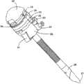
参见图1,可观察到,套管针包括连接(通常是一体地)到空心圆筒形套管3的本体5,套管3的远端是扩口的,即,根据相对于套管3的纵向轴线的垂直平面倾斜的平面切割。盖1以可移除的方式连接到本体5并设置有圆柱形充填器,充填器在其远端处以通常是口哨形的末端4结束,末端4能够刺入组织。当盖1连接到本体5时,充填器插入到套管3中,仅末端4从套管3突伸出,以便当医生操作盖1-本体5的组件并按压末端4抵靠着腹壁时,末端切开腹壁的组织,从而将套管3的远端部分引入到腹腔中。在上述切开结束时,移除盖1和充填器,以允许穿过作为通道操作的套管3将手术器械引入到腹腔中。本体5设置有外部阀2,阀2用于仍通过套管3将用于喷注(例如,用于气体引入)和灌洗的外部设备与腹腔连接。本体5一体地容纳其它阀(在图1中未示出),确保甚至当存在手术器械时也密封套管3。Referring to Figure 1, it can be observed that the trocar comprises a
为了便于切开,在现有技术中已知一些套管针,其中末端4和有可能的盖1以特定方式摇动,末端4可以包括一个或多个刀片或不包括刀片(不具有刀片的套管针也称作无刀片套管针)。In order to facilitate incision, trocars are known in the prior art in which the
文献US 5879332描述一种套管针,其具有非圆形对称的盖。Document US 5879332 describes a trocar with a non-circular symmetrical cap.
文献WO 2006/061514描述一种切割套管针,其设置有具有螺旋刀刃的末端。Document WO 2006/061514 describes a cutting trocar provided with a tip with a helical blade.
文献US 5662673描述一种套管针,其具有末端,末端具有螺旋切割刀片。Document US 5662673 describes a trocar having a tip with a helical cutting blade.
文献WO 03/026512描述一种用于套管针的无刀片充填器,其具有螺旋扭转末端。Document WO 03/026512 describes a bladeless obturator for trocars with a helically twisted tip.
但是,所有现有技术的套管针都有一些缺点,主要是由于刺入组织同时保持套管外壁与腹壁之间的密封较为困难。However, all prior art trocars have some disadvantages, primarily due to the difficulty of penetrating tissue while maintaining a seal between the outer wall of the cannula and the abdominal wall.
首先,医生必须小心地操作具有设置有切割刀片的充填器的套管针,以避免损伤到内部器官或血管。First, the doctor must carefully handle the trocar with the obturator provided with the cutting blade in order to avoid damage to internal organs or blood vessels.
此外,套管针头部的不良可控性增加了刺入组织的难度,即,盖-本体组件的不良人体工程学性能增加了刺入组织的难度。Furthermore, the poor controllability of the trocar head increases the difficulty of penetrating tissue, ie the poor ergonomics of the cap-body assembly increases the difficulty of penetrating tissue.
同样,无刀片套管针通常需要由医生切开初步组织切口,以允许充填器和套管引入到腹腔中。Likewise, bladeless trocars typically require a preliminary tissue incision to be made by the physician to allow introduction of the obturator and cannula into the abdominal cavity.
此外,设置有切割刀片的充填器和无刀片的充填器都损坏它们刺入到其中的组织,使套管与所刺入的组织之间的间隙的密封性能劣化,并使手术后的切口愈合更加困难。In addition, both obturators provided with cutting blades and obturators without blades damage the tissues into which they are pierced, deteriorate the sealing performance of the gap between the cannula and the pierced tissues, and heal the incision after surgery more difficult.
在该上下文中,介绍根据本发明提出的解决方案,以克服上述问题。In this context, the solution proposed according to the present invention is presented to overcome the above-mentioned problems.
因此,本发明的目的是,在由腹腔镜技术执行介入的过程中,允许以可靠的、多功能的、简单的、对于操作者舒适而对于病人安全的方式将诸如手术刀、清洗和/或吸引套管、以及光学装置等手术器械引入到病人的腹腔中。Therefore, the object of the present invention is to allow, during interventions performed by laparoscopic techniques, to use, in a reliable, multifunctional, simple, comfortable for the operator and safe for the patient, tools such as scalpels, cleaning and/or Surgical instruments such as suction cannula, and optics are introduced into the patient's abdominal cavity.
本发明的特定主题是一种套管针,所述套管针包括:本体,所述本体连接到中空圆筒形套管,充填器可插入到所述中空圆筒形套管中;以及顶盖,所述顶盖具有顶部,能够以可移除的方式连接到所述本体,其特征在于,所述顶盖的平面图为具有半径R1的圆形,其中,所述顶盖的具有穿过顶部的第一平面的第一部分具有第一上部轮廓,所述第一上部轮廓包括中心部分,所述中心部分具有不小于所述顶盖的平面图的圆形半径R1的曲率半径R2,并且其中,所述顶盖的具有垂直于所述第一平面并穿过顶部的第二平面的第二部分具有第二上部轮廓,所述第二上部轮廓包括后部部分,所述后部部分具有大于所述顶盖的平面图的圆形半径R1的曲率半径R4。A particular subject of the invention is a trocar comprising: a body connected to a hollow cylindrical cannula into which an obturator can be inserted; and a top a cover, the top cover having a top capable of being removably connected to the body, characterized in that the top cover is circular in plan view with a radius R1, wherein the top cover has a through The first planar first portion of the top has a first upper profile comprising a central portion having a radius of curvature R2 not less than the circular radius R1 of the plan view of the roof, and wherein, A second portion of the top cover having a second plane perpendicular to the first plane and passing through the top has a second upper profile including a rear portion having a shape greater than the The radius of curvature R4 of the circular radius R1 of the planar view of the top cover.
在任何情况下,根据本发明,比例R2/R1可以包括在从1.00至1.50,优选从1.10至1.40,更优选从1.15至1.35,进一步更优选从1.20至1.30的范围内。In any case, according to the invention, the ratio R2/R1 may be comprised in the range from 1.00 to 1.50, preferably from 1.10 to 1.40, more preferably from 1.15 to 1.35, still more preferably from 1.20 to 1.30.
仍根据本发明,比例R4/R1可以包括在从1.05至1.60,优选从1.15至1.50,更优选从1.25至1.40,进一步更优选从1.30至1.35的范围内。Still according to the invention, the ratio R4/R1 may be comprised in the range from 1.05 to 1.60, preferably from 1.15 to 1.50, more preferably from 1.25 to 1.40, still more preferably from 1.30 to 1.35.
此外,根据本发明,所述第二上部轮廓进一步包括前部部分,所述前部部分具有曲率半径R3,以使比例R3/R1包括在从0.60至1.10,优选从0.70至1.00,更优选从0.75至0.95,进一步更优选从0.80至0.90的范围内,其中,前部部分的曲率半径R3优选小于后部部分的曲率半径R4。Furthermore, according to the invention, said second upper profile further comprises a front portion having a radius of curvature R3 so that the ratio R3/R1 is comprised from 0.60 to 1.10, preferably from 0.70 to 1.00, more preferably from 0.75 to 0.95, more preferably in the range from 0.80 to 0.90, wherein the radius of curvature R3 of the front portion is preferably smaller than the radius of curvature R4 of the rear portion.
在任何情况下,根据本发明,所述第二上部轮廓的前部部分和后部部分可以通过具有小于R3的曲率半径的中间部分而形成圆角,所述第二上部轮廓进一步优选包括具有小于R3的曲率半径的前端部分和/或具有小于R4的曲率半径的后端部分。In any case, according to the invention, the front and rear parts of said second upper profile may be rounded by a middle part having a radius of curvature smaller than R3, said second upper profile further preferably comprising The front end portion having a radius of curvature of R3 and/or the rear end portion having a radius of curvature smaller than R4.
仍根据本发明,所述顶盖的平面图可以是具有半径R1的圆形,并沿着在前面定位的圆弧变扁平,所述圆弧优选范围从90°至120°。Still according to the invention, said roof may be circular in plan with radius R1 and flattened along a frontally positioned arc of circle preferably ranging from 90° to 120°.
此外,根据本发明,所述顶盖的平面图的圆形半径R1包括在从16.5至22.5mm,优选从17.5至21.5mm,更优选从18.5至20.5mm,进一步更优选从19至20mm的范围内。Furthermore, according to the invention, the circular radius R1 of the plan view of the top cover is comprised in the range from 16.5 to 22.5 mm, preferably from 17.5 to 21.5 mm, more preferably from 18.5 to 20.5 mm, still more preferably from 19 to 20 mm .
在任何情况下,根据本发明,所述顶盖可以是能够通过弹性U形连接件以可移除的方式连接到所述本体,所述弹性U形连接件具有与一体容纳在所述本体中的U形弹簧相互作用的两个侧臂,所述弹性连接件的两个侧臂设置有各自的按钮并以各自从“U”形向外突出的脊状突起结束,所述弹性连接件的两个侧臂的端部脊状突起可插入到所述本体的对应通孔中,由此,当位于静止位置时,所述弹簧保持所述弹性连接件的两个侧臂分隔开,以使端部脊状突起由通孔的对应边缘锁定,而当侧面按钮被按压以超过弹簧的强度时,端部脊状突起从所述孔的所述边缘脱离,由此从所述本体释放所述连接件和所述顶盖。In any event, according to the invention, said top cover may be removably connectable to said body by means of an elastic U-shaped connector having a The two side arms of the U-shaped spring interacting with each other, the two side arms of the elastic connector are provided with respective buttons and end with a ridge each protruding outward from the "U" shape, the elastic connector's The end ridges of the two side arms are insertable into corresponding through-holes of the body whereby, when in the rest position, the spring keeps the two side arms of the elastic connector apart for The end ridge is locked by the corresponding edge of the through hole, and when the side button is pressed to exceed the strength of the spring, the end ridge disengages from the edge of the hole, thereby releasing the end ridge from the body. The connectors and the top cover.
仍根据本发明,所述本体可以包括鸭嘴阀,所述鸭嘴阀容纳在具有环形覆盖件的容器中,环形元件通过以可转动的方式连接的机械装置以可转动的方式连接到所述覆盖件,优选以可移除的方式连接到所述覆盖件,环形元件设置有致动装置,环形元件和覆盖件能够呈现其中所述致动装置打开鸭嘴阀的构造。Still according to the invention, said body may comprise a duckbill valve housed in a container having an annular cover, the annular element being rotatably connected to said A cover, preferably removably connected to said cover, an annular element provided with actuating means, the annular element and cover being able to assume a configuration in which said actuating means opens a duckbill valve.
此外,根据本发明,所述本体可以包括容纳在容器中的自定心密封装置,所述密封装置按顺序包括:Furthermore, according to the invention, said body may comprise self-centering sealing means housed in a container, said sealing means comprising in sequence:
-近端环形托架,- proximal ring bracket,
-近端膜,其具有彼此部分地重叠以形成圆锥形表面的多个刚弹性元件,- a proximal membrane having a plurality of rigid elastic elements partially overlapping each other to form a conical surface,
-中间膜,其在中心设置有通孔,- an intermediate membrane provided with a through hole in the center,
-中间环形托架,- middle ring bracket,
-远端膜,其具有彼此部分地重叠以形成圆锥形表面的多个软弹性元件,以及- a distal membrane having a plurality of soft elastic elements partially overlapping each other to form a conical surface, and
-远端环形托架,- Distal ring bracket,
其中,近端膜的刚弹性元件插入到中间膜的中心孔中并与远端膜的软弹性元件相接触,中间膜优选在容器内可径向移动,由此,所述装置也可以在容器内移动。wherein the rigid elastic element of the proximal membrane is inserted into the central hole of the intermediate membrane and is in contact with the soft elastic element of the distal membrane, the intermediate membrane is preferably radially movable within the container, whereby the device can also be placed in the container move within.
在任何情况下,根据本发明,近端环形托架可以在远端表面上设置有多个销,所述多个销能够插入到近端膜的刚弹性元件所设置的对应多个孔中、插入到中间膜的对应多个孔中、并插入到中间托架的对应多个孔中,并且中间环形托架在远端表面上设置有多个销,所述多个销能够插入到远端膜的软弹性元件的对应多个孔中并插入到远端托架的对应多个孔中。In any case, according to the invention, the proximal annular bracket can be provided on the distal surface with a plurality of pins that can be inserted into corresponding holes provided by the rigid elastic element of the proximal membrane, Inserted into a corresponding plurality of holes of the intermediate membrane and inserted into a corresponding plurality of holes of the intermediate bracket, and the intermediate annular bracket is provided with a plurality of pins on the surface of the distal end, the plurality of pins can be inserted into the distal end The soft elastic element of the membrane is inserted into the corresponding plurality of holes of the distal bracket and inserted into the corresponding plurality of holes of the distal bracket.
仍根据本发明,以可转动的方式连接到覆盖件的环形元件可以是容纳自定心密封装置的容器的一部分。Still according to the invention, the annular element rotatably connected to the cover may be part of a container housing the self-centring sealing means.
此外,根据本发明,充填器可以在远端处以末端结束,所述末端具有基部和顶点,其中充填器的末端跟随从基部到顶点的螺旋旋转,所述螺旋旋转的范围从30°至60°,优选从35°至55°,更优选从40°至50°,进一步更优选从44°至47°,所述充填器优选是无刀片的。Furthermore, according to the invention, the obturator may end at the distal end with a tip having a base and an apex, wherein the obturator's tip follows a helical rotation from the base to the apex, said helical rotation ranging from 30° to 60° , preferably from 35° to 55°, more preferably from 40° to 50°, even more preferably from 44° to 47°, the filler is preferably bladeless.
在任何情况下,根据本发明,所述末端的顶点可以相对于所述充填器的纵向轴线不对齐,优选的方式为所述末端的顶点与所述充填器的纵向轴线分隔开一段距离,所述距离的范围从围绕所述末端基部的圆的半径的20%至75%,更优选从30%至65%,进一步更优选从40%至55%,甚至更优选从45%至50%。In any event, according to the invention, the apex of the tip may be misaligned with respect to the longitudinal axis of the obturator, preferably in such a way that the apex of the tip is spaced from the longitudinal axis of the obturator by a distance, Said distance ranges from 20% to 75%, more preferably from 30% to 65%, still more preferably from 40% to 55%, even more preferably from 45% to 50% of the radius of the circle around the base of said tip .
仍根据本发明,所述充填器的远端圆柱形部分和/或近端圆柱形部分可以具有大于中央圆柱形部分直径的直径,所述充填器的末端从基部到顶点的长度优选包括在从24.5至32.5mm,优选从26至31mm,更优选从27至30mm,进一步更优选从28至29mm的范围内。Still according to the invention, the distal cylindrical part and/or the proximal cylindrical part of the obturator may have a diameter greater than the diameter of the central cylindrical part, the length of the distal end of the obturator from the base to the apex preferably being comprised between 24.5 to 32.5mm, preferably from 26 to 31mm, more preferably from 27 to 30mm, even more preferably from 28 to 29mm.
根据本发明的无刀片套管针包括特殊成形的顶盖-本体组件,其非常便于使用以及套管针的插入精度。实际上,顶盖-本体组件的形状使套管针的柄非常易于操纵并符合人体工程学,从而允许医生更好的控制套管针。在此方面,柄允许左手使用者和右手使用者都能最佳抓握,并允许在若干种位置中使用,以便于保持高精度和安全的良好操作性。The bladeless trocar according to the present invention includes a specially shaped cap-body assembly which is very easy to use and precision of insertion of the trocar. In fact, the shape of the cap-body assembly makes the handle of the trocar very manoeuvrable and ergonomic, allowing better control of the trocar by the physician. In this respect, the handle allows an optimal grip for both left-handed and right-handed users and allows use in several positions in order to maintain good maneuverability with high precision and safety.
此外,根据本发明的套管针可以进一步设置有优选由聚碳酸酯形成的充填器,所述充填器由于末端的特定形状而具有扩张的末端。特别地,末端具有特定的螺旋形状,所述螺旋形状赋予末端适当的机械特性,不需要医生做初步切口就允许末端容易地刺入腹腔内。这允许在插入阶段期间最小化对组织的损伤。此外,在根据本发明的套管针的该特定实施方式中,末端上无刀片消除了或至少最小化了损伤内部器官或血管的风险。Furthermore, the trocar according to the invention may further be provided with an obturator, preferably formed of polycarbonate, which has a flared tip due to the specific shape of the tip. In particular, the tip has a specific helical shape that imparts appropriate mechanical properties to the tip, allowing easy penetration of the tip into the abdominal cavity without the need for an initial incision by the physician. This allows for minimal damage to the tissue during the insertion phase. Furthermore, in this particular embodiment of the trocar according to the invention, the absence of blades on the tip eliminates or at least minimizes the risk of damaging internal organs or blood vessels.
现在将通过特别参见附图根据本发明的优选实施方式以例示而非限制的方式来描述本发明,其中:The invention will now be described, by way of illustration and not limitation, according to preferred embodiments of the invention, with particular reference to the accompanying drawings, in which:
图1示出现有技术的套管针的示意性右视图;Figure 1 shows a schematic right side view of a prior art trocar;
图2示出根据本发明的设置有充填器的套管针的一优选实施方式的立体图(图2a)、主视图(图2b)、左视图(图2c)、俯视平面图(图2d)以及后视图(图2e);Figure 2 shows a perspective view (Figure 2a), a front view (Figure 2b), a left side view (Figure 2c), a top plan view (Figure 2d) and a rear view of a preferred embodiment of a trocar provided with an obturator according to the invention View (Figure 2e);
图3示出图2的套管针的立体分解图;Figure 3 shows an exploded perspective view of the trocar of Figure 2;
图4示出图2的套管针的弹性连接件的立体图;Fig. 4 shows a perspective view of the elastic connector of the trocar of Fig. 2;
图5示出从图2的套管针本体的第一部件上方观察时的立体图;Figure 5 shows a perspective view as viewed from above the first part of the trocar body of Figure 2;
图6示出从图2的套管针本体的第二部件下方观察时的立体图;Figure 6 shows a perspective view from below the second part of the trocar body of Figure 2;
图7示出从图2的套管针本体的第三部件下方观察时的立体图;Figure 7 shows a perspective view from below the third part of the trocar body of Figure 2;
图8示出从图2的套管针的顶盖下方观察时的立体图;Figure 8 shows a perspective view from below the cap of the trocar of Figure 2;
图9示出从图2的套管针本体的第四部件下方观察时的立体图;Figure 9 shows a perspective view from below the fourth part of the trocar body of Figure 2;
图10示出从图2的套管针本体的第五部件上方观察时的立体图;Figure 10 shows a perspective view as viewed from above the fifth part of the trocar body of Figure 2;
图11示出从图2的套管针的自定心密封装置的上方观察时的立体图;Figure 11 shows a perspective view from above of the self-centering sealing device of the trocar of Figure 2;
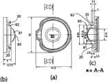
图12示出图11的自定心密封装置的从下方观察时的立体图(图12a)、仰视平面图(图12b)、沿图12b的剖切面AA的截面图(图12c)、以及立体分解图(图12d);12 shows a perspective view ( FIG. 12 a ), a bottom plan view ( FIG. 12 b ), a sectional view along the section plane AA of FIG. 12 b ( FIG. 12 c ), and a perspective exploded view of the self-centering seal of FIG. 11 . (Fig. 12d);
图13示出图11的自定心密封装置的第一部件的立体图(图13a)、第二部件的立体图(图13b)、第三部件的立体图(图13c)、第四部件的立体图(图13d)、第五部件的立体图(图13e)以及第六部件的立体图(图13f);Figure 13 shows a perspective view of the first part (Fig. 13a), a perspective view of the second part (Fig. 13b), a perspective view of the third part (Fig. 13c), a perspective view of the fourth part (Fig. 13d), a perspective view of the fifth part (Fig. 13e) and a perspective view of the sixth part (Fig. 13f);
图14示出图2的套管针的俯视平面图(图14a)、沿图14a的剖切面AA的截面图(图14b)、沿图14a的剖切面BB的截面图(图14c)、以及沿图14a的剖切面CC的截面图(图14d);Figure 14 shows a top plan view of the trocar of Figure 2 (Figure 14a), a cross-sectional view along section plane AA of Figure 14a (Figure 14b), a section view along section plane BB of Figure 14a (Figure 14c), and a section along A cross-sectional view of the cutting plane CC of FIG. 14a (FIG. 14d);
图15示出图2的套管针的充填器的主视图(图15a)、俯视平面图(图15b)、左视图(图15c)、沿图15a的剖切面AA的截面图(图15d)、沿图15c的剖切面SS的截面图(图15e)、沿图15c的剖切面RR的截面图(图15f)、沿图15c的剖切面FF的截面图(图15g)、沿图15c的剖切面WW的截面图(图15h)、沿图15c的剖切面QQ的截面图(图15i)、仰视平面图(图15j)、以及放大仰视平面图(图15k);Fig. 15 shows a front view (Fig. 15a), a top plan view (Fig. 15b), a left side view (Fig. 15c), a cross-sectional view along the cutting plane AA of Fig. 15a (Fig. 15d), the obturator of the trocar of Fig. 2, Sectional view along the sectional plane SS of Figure 15c (Figure 15e), a sectional view along the sectional plane RR of Figure 15c (Figure 15f), a sectional view along the sectional plane FF of Figure 15c (Figure 15g), a section along Figure 15c Sectional view of section WW (Fig. 15h), section view along section QQ of Fig. 15c (Fig. 15i), bottom plan view (Fig. 15j), and enlarged bottom plan view (Fig. 15k);
图16示出图2的套管针的顶盖的俯视平面图(图16a)、后视图(图16b)、仰视平面图(图16c)、沿图16a的剖切面FF的截面图(图16d)、沿图16a的剖切面BB的截面图(图16e)、沿图16a的剖切面DD的截面图(图16f)、沿图16a的剖切面HH的截面图(图16g)、沿图16a的剖切面AA的截面图(图16h)、以及沿图16a的剖切面GG的截面图(图16i);Fig. 16 shows a top plan view (Fig. 16a), a rear view (Fig. 16b), a bottom plan view (Fig. 16c), a cross-sectional view along the section plane FF of Fig. 16a (Fig. 16d) of the cap of the trocar of Fig. 2 , Sectional view along the sectional plane BB of Figure 16a (Figure 16e), a sectional view along the sectional plane DD of Figure 16a (Figure 16f), a sectional view along the sectional plane HH of Figure 16a (Figure 16g), a section along Figure 16a A sectional view of the section AA ( FIG. 16 h ), and a sectional view along the section GG of FIG. 16 a ( FIG. 16 i );
图17示出图7的第三部件的俯视平面图(图17a)、后视图(图17b)以及沿图17a的剖切面AA的截面图(17c);Fig. 17 shows a top plan view (Fig. 17a), a rear view (Fig. 17b) and a sectional view (17c) along the cutting plane AA of Fig. 17a of the third part of Fig. 7;
图18示出图9的第四部件的从上方观察时的立体图(图18a)、俯视平面图(图18b)、左视图(图18c)、右视图(图18d)、以及后视图(图18e);以及Figure 18 shows a perspective view (Figure 18a), a top plan view (Figure 18b), a left side view (Figure 18c), a right side view (Figure 18d), and a rear view (Figure 18e) of the fourth component of Figure 9 as viewed from above ;as well as
图19以若干种构造示出图2的套管针的一部分的五个立体图。19 shows five perspective views of a portion of the trocar of FIG. 2 in several configurations.
在这些图中,相同参考数字用于相似元件。In these figures, the same reference numerals are used for similar elements.
特别地,在图中所示的尺寸是举例说明而不意图限制本发明保护范围,除非有明确的相反说明。In particular, the dimensions shown in the figures are illustrative and not intended to limit the scope of protection of the present invention, unless expressly stated to the contrary.
在下文中,将清楚参考根据本发明的套管针的一优选实施方式,其包括特定的无刀片充填器,所述充填器具有螺旋形末端。但是,可以理解,根据本发明的套管针可以包括任何其它充填器,甚至设置有刀片以及设置有具有不同于所述螺旋形状(例如,口哨形)的末端的其它充填器,这些其它充填器仍落在本发明的保护范围内。In the following, explicit reference will be made to a preferred embodiment of the trocar according to the invention comprising a specific bladeless obturator with a helical tip. However, it will be appreciated that a trocar according to the invention may comprise any other obturator, even provided with a blade and with a tip having a different helical shape (eg whistle), which other obturator Still fall within the protection scope of the present invention.
参见图2和图3,可观察到,根据本发明的套管针的优选实施方式包括顶盖10,顶盖10可以连接到在中心设置有通孔的下盖13,然后通过与U形弹簧12相互作用的弹性连接件11连接到第一环形元件14,如将在下文详细描述的。Referring to Fig. 2 and Fig. 3, it can be observed that the preferred embodiment of the trocar according to the present invention includes a
第一环形元件14可以转而连接到第二环形元件15,以使第一和第二环形元件14和15作为密封装置24的容器操作。The first
所述套管针进一步包括环形覆盖件25,环形覆盖件25能够封闭容器26,在容器26的底部设置有通孔(在图10中示出并以参考数字27指出),容器26容纳中空圆筒形套管29的近端28(套管29的远端向外扩张,优选45度)。套管29的近端28设置有前入口/出口管道30,管道30设置有由相应阀32控制的龙头31,以允许套管29的内部与诸如外部的(例如,用于引入气体的)喷注设备和清洗设备相连接。在此方面,密封鸭嘴阀33容纳在套管29的近端28中。套管29的外壁在中央设置有螺旋螺纹36。特别地,从下盖13到容器26的部件的组装形成套管针的本体,所述本体在图1中用参考数字5标示。The trocar further comprises an
充填器23能够插入到套管29中,充填器23以远侧末端37结束,远侧末端37具有将在下面例示的特殊螺旋形状。The
特别地,还参见图4,可观察到,弹性连接件11是U形的并具有两个侧臂,两个侧臂在接近端部处设置有各自的按钮16,并且两个侧臂的端部设置有从U形向外突出的各自的脊状突起17。进一步参见图5和图6,当顶盖10与下盖13和第一环形元件14组装在一起时(如图2所示),弹性连接件11侧臂的端部脊状突起17插入到下盖13的对应通孔18和第一环形元件14的对应通孔19中;在该已组装配置中,当位于静止位置时,弹簧12保持弹性连接件11的侧臂分开(与侧臂的面向U形内侧的表面相互作用),以使端部脊状突起17被第一环形元件14的孔19的边缘锁定在组装位置。连接在弹性连接件11的侧臂之间的中间臂的顶部设置有圆形通孔21,在已组装配置中,顶盖10的内表面顶部的对应圆形突出部22(在图8中示出)插入到通孔21中,突出部22构成用于固定套管针充填器23的支座。从图2的已组装配置开始,通过按压两侧按钮16以超过弹簧12的强度,可以使连接件11的脊状突起17与第一环形元件14的孔19和下盖13的孔18的边缘脱离,使连接件11的侧臂滑动并因此从套管针本体释放连接件11和顶盖10,以允许抽出充填器23。In particular, referring also to FIG. 4 , it can be seen that the
参见图7和图17,可观察到,第二环形元件15在下表面上设置有两个脊状突起20和20′,脊状突起20和20′设置在相对于中心孔80沿直径相对的位置中,绕中心孔80在径向增加的距离处存在机械致动器81和圆筒形凸起82(比致动器81突出的少)。特别地,机械致动器81根据圆筒形表面部分而成形,其远端是曲线的,以限定两个沿直径相对的曲线突出部83(在图中所示的套管针的优选实施方式中,这些突出部83沿与两个脊状突起20和20′定位所沿的直径相垂直的直径定位)。7 and 17, it can be seen that the
参见图9和图10,可观察到,环形覆盖件25在其底部处设置有四个销34,而容器26设置有四个对应支座(两个前支座以35指出,而两个后支座以35′指出):通过将销34插入到支座35和35′中,环形覆盖件25能够一体地连接到容器26。容器26在其底部处设置有通孔27(套管29可以滑动通过通孔27)。容器26的外壁包括前槽口38,其中龙头31和相应阀32可以容纳在槽口38中,因此确定套管29在容器26内的径向位置。此外,容器26的内壁包括后肋部39,后肋部39与套管29近端28的后舌片40相互作用,以与覆盖件25一起确定套管29在容器26内的纵向位置;特别地,后舌片40可以进一步与容器26的一对后支座35′相互作用,该对后支座35′(其与管道30-龙头31组件容纳在前槽口38中的结构相结合、或替代管道30-龙头31组件容纳在前槽口38中的结构)确定套管29在同一容器26内的径向位置。如还从图2中导出的,容器26在远端处设置有两个侧突出部41,侧突出部41允许更好地操作套管针,如下面将描述的。Referring to Figures 9 and 10, it can be observed that the
参见图18,可观察到,环形覆盖件25进一步围绕中心孔84设置有两个沿直径相对的导槽85和85′,导槽85和85′形成为环形的一部分,各自在一端处分别以约束形状的区域86和86′结束。与约束区域86和86′相对应,环形覆盖件25包括两个分别为87和88的侧杆,当操作时,侧杆87和88允许改变相应区域86和86′的形状,从而允许第二环形元件15的脊状突起20和20′在导槽85和85′中滑动,或允许第二环形元件15与覆盖件25脱离,如将在下面详细描述的。18, it can be observed that the
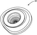
图11至图13示出容纳在第一和第二环形元件14和15中的密封装置24。特别地,根据环形元件14和15成形的密封装置24(即,具有沿着前置的圆弧、优选范围从90°至120°的圆弧略微变扁的圆形平面)是自定心的多膜装置,包括:11 to 13 show the sealing means 24 housed in the first and
-近端环形托架42,其在远端表面上设置有多个(优选12个)销43,- a proximal
-中间环形托架44,其设置有多个(优选12个)通孔45,并在远端表面上设置有多个(优选12个)销46(相对于孔45明显不对齐),- an intermediate
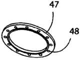
-远端环形托架47,其设置有多个(优选12个)通孔48,- a distal
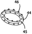
-中间膜49(具有根据环形元件14和15成形的平面),其在中心处设置有由环60界定的通孔62,环60设置有多个(优选12个)通孔50,突出边缘61(朝向套管针的远端定向)从该膜延伸,- an intermediate membrane 49 (with a plane shaped according to the
-近端膜,其具有彼此部分地重叠以形成圆锥形表面的六个刚弹性元件(rigid elasticelement)51,其中,每个元件51包括通过圆筒形部分57连接到环形部分53的圆锥形表面部分52,其中,圆锥形部分52优选具有大于1/6周角(即60°)并优选小于3/6周角(即180°)的角范围,但是圆形部分53具有不大于、优选小于1/6周角的角范围,圆形部分53设置有一个或多个通孔54,通孔54的数量优选等于近端环形托架42的多个销43的数量的1/6(在图中所示的优选实施方式中,这个数量等于2),- a proximal membrane with six rigid
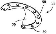
-远端膜,其具有彼此部分地重叠以形成圆锥形表面的六个软弹性元件(soft elasticelement)55,其中,每个元件55包括连接到环形部分58的圆锥形表面部分56,其中,圆锥形部分56和圆形部分58具有优选大于1/6周角(即60°)、更优选大于1/2周角(即180°),且更优选小于5/6周角(即300°)的角范围,圆形部分58设置有一个或多个通孔59(等于包括在圆形部分58的角范围内的中间托架44的销46的数量,在图中所示的优选实施方式中,这个数量等于9)。- distal membrane, it has six soft elastic elements (soft elasticelement) 55 that partially overlap each other to form a conical surface, wherein each
如在图12中更好地示出,近端膜位于近端托架42与中间膜49之间,中间托架44容纳在中间膜49中并与环60的远端表面接触并位于突出边缘61内,而远端膜位于中间托架44与远端托架47之间,以使近端托架42的销43插入到近端膜的元件51的孔54中、插入到中间膜49的孔50中、并插入到中间托架44的孔45中,并且使中间托架44的销46插入到远端膜的元件55的孔59中并插入到远端托架47的孔48中。特别地,当装置24组装时,近端膜的元件51插入到中间膜49的中心孔62中,接触远端膜的元件55。中间膜49可在由环形元件14和15形成的壳体中沿径向移动,从而允许整个装置24在组装后具有相同的移动性。这允许手术器械以相对于套管29的纵向轴线成若干个角度的方式穿过套管针插入到病人的腹腔中。As better shown in FIG. 12, the proximal membrane is located between the
特别地,当充填器23插入到套管29中或至少一个手术器械穿过套管针插入到病人的腹腔中时,装置24确保腹腔的密封(避免生物流体的泄漏,通常保持与外部的压力差);替代地,当充填器23不插入到套管29中并且任何其它手术器械也不插入到腹腔中时,鸭嘴阀33确保腹腔的密封。In particular, when the
图14示出处于图2的组装配置中的套管针的一些部分。关于制成套管针部件的材料,顶盖10和下盖13、连接件11、第一和第二环形元件14和15、充填器23、覆盖件25、容器26、套管29、以及龙头31优选由聚碳酸酯制成;弹簧12优选由弹簧钢(即,具有高含碳率的钢,含碳率优选从0.80%至0.90%范围,因此特别硬)制成;龙头31的阀32优选由聚乙烯制成;鸭嘴阀33优选由硅树脂制成。关于密封装置24,近端托架42、中间托架44和远端托架47优选由聚碳酸酯制成;近端膜优选由laprene(苯乙烯-乙烯-丁二烯-苯乙烯嵌段共聚物)制成;中间膜49和远端膜优选由丁苯橡胶(SBR)和丁晴橡胶(NBR)的混合物制成。此外,使用生物相容型的粘合剂来组装套管针。FIG. 14 shows portions of the trocar in the assembled configuration of FIG. 2 . Regarding the materials from which the trocar parts are made, the
图15示出根据本发明的套管针的优选实施方式的充填器23,其中,可见,充填器23的远端部分65和近端部分66优选具有大于中央圆柱67的直径。根据本发明的套管针的创新性特点在于远侧末端37具有特殊的螺旋形状。首先,还是参见图15,可观察到,延伸长度L的末端37跟随从基部到顶点70的螺旋旋转,上述螺旋旋转的范围介于从30°至60°,优选从35°至55°,更优选从40°至50°,进一步更优选的从44°至47°(在图中所示的优选实施方式中等于46°)。与远端部分65和近端部分66的最大直径一致的充填器23的最大直径(以及因此的套管29的最大直径)可以变化(优选地,根据5、10和12mm的标准尺寸)。末端37的长度L固定在一值,该值优选在从24.5至32.5mm、更优选从26至31mm、进一步更优选从27至30mm,甚至更优选从28至29mm的范围内变化(在图中所示的套管针的优选实施方式中,L等于28.5mm)。此外,末端37的顶点70相对于充填器23的纵向轴线不对齐;特别地,顶点70(优选其几何质心)与充填器23的轴线分隔开一距离,所述距离优选范围为末端37的基部的半径(与远端部分65和近端部分66的半径一致)的从20%至75%,更优选这个半径的从30%至65%,进一步更优选这个半径的从40%至55%,甚至更优选这个半径的从45%至50%(在图中所示的套管针的优选实施方式中,末端37的基部的半径——即,远端部分65和近端部分66的半径——等于6.3mm,并且顶点70相对于中心不对齐而相差3.0mm)。特别地,如图2所示,充填器23优选组装在套管针中,以使末端37的顶点70在前面不对齐,即,朝向末端37不对齐。充填器23的末端37的特殊螺旋形状具有特别的机械特性,其允许它通过使腹壁的组织扩张,而不是割裂或切割腹壁的组织,来容易地刺入。FIG. 15 shows the
图16详细地示出顶盖10,示出其形状使套管针非常便于抓握并符合人体工程学。在此方面,可观察到,顶盖10的平面图为具有半径R1的圆形,沿在前面定位的圆弧略微变扁,圆弧优选范围从90°至120°。半径R1固定在一值,所述值优选在从16.5至22.5mm、更优选从17.5至21.5mm、进一步更优选从18.5至20.5mm、甚至更优选从19至20mm的范围内变化(在图中所示的套管针的优选实施方式中,R1等于19.6mm)。Figure 16 shows the
通过用平行于连接件11的按钮16的壳体并穿过顶部的平面切割顶盖10(图16e所示)所获得的部分具有上部轮廓(或近端轮廓,属于接触操作套管针的医生手掌的表面),所述上部轮廓包括具有稍大于平面图半径R1的弯曲半径R2的中央部分。优选地,R2/R1之比固定在从1.00至1.50、更优选从1.10至1.40、进一步更优选从1.15至1.35、甚至更优选从1.20至1.30的范围内(在图中所示的优选实施方式中,R1等于19.6mm,而R2等于24.5mm)。The part obtained by cutting the top cover 10 (shown in FIG. 16e ) with a plane parallel to the housing of the
通过用垂直于前一平面并穿过顶部的平面切割顶盖10所获得的部分(图16h所示)具有上部轮廓(属于接触操作套管针的医生手掌的表面),所述上部轮廓包括具有弯曲半径R3的前部部分71和具有弯曲半径R4的后部部分72。特别地,前部半径R3小于后部半径R4;优选地,前部半径R3稍小于平面半径R1,而后部半径R4稍大于同一半径R1。优选地,R3/R1之比固定在从0.60至1.10、更优选从0.70至1.00、进一步更优选从0.75至0.95、甚至更优选从0.80至0.90的范围内(在图中所示的优选实施方式中,R1等于19.6mm,而R3等于16.93mm)。优选地,R4/R1之比固定在从1.05至1.60、更优选从1.15至1.50、进一步更优选从1.25至1.40、甚至更优选从1.30至1.35的范围内(在图中所示的优选实施方式中,R1等于19.6mm,而R4等于25.91mm)。在图16所示的顶盖10的优选实施方式中,可观察到,上部轮廓的前部部分71和后部部分72由具有小于R3的弯曲半径的中间部分连接,并且上部轮廓进一步包括具有稍小于R3的弯曲半径的前端部分和具有稍小于R4的弯曲半径的后端部分。The part obtained by cutting the
参见图2,可观察到,根据本发明的套管针的柄的整体高度可以通过改变从顶盖10向下到容器26的组成元件的高度而容易地调整,以改善套管针的柄的操纵性和人体工程学性能。Referring to Fig. 2, it can be observed that the overall height of the handle of the trocar according to the present invention can be easily adjusted by changing the height of the constituent elements from the
总的来说,所述装置主要是通过使用通过模制所获得的塑料材料而制成,然后通过胶粘、通过压制而固定或通过使用螺钉来组装部件。In general, the device is mainly produced by using plastic material obtained by molding, and then assembling the parts by gluing, fixing by pressing or by using screws.
根据本发明的套管针的使用方式非常简单。实际上,仍参见图2,医生通过将顶盖10的后部和本体10的后部放置在手掌中并且使用供手指(优选中指和无名指)夹持的两个远侧突出部41,来操作套管针;换句话说,套管针本体包在拳头中,而其套管29从压着两个远侧突出部41的两个手指之间的间隙伸出来。在推动套管针的阶段期间,有利的是还施加略微扭转的顺时针运动,从而便于充填器23的末端37和套管29刺入到腹腔中,由于末端37的特殊螺旋形状,不用割裂即可分开腹壁的组织。这种扭转运动进一步允许套管29的中央螺旋螺纹36粘附到腹壁,从而便于套管针机械连接到腹部,并消除对用于将套管29固定到腹壁的缝合线或夹子的需要。The trocar according to the invention is very simple to use. In practice, still referring to Figure 2, the physician operates by placing the rear of the
一旦完成将根据本发明的套管针引入到腹腔中,则医生按压(例如,用手的拇指和食指)连接件11的两侧按钮16,由此移除顶盖10并抽出充填器23。在抽出充填器23的过程中,通过鸭嘴阀33和密封装置24来避免生物流体的泄漏。Once the introduction of the trocar according to the invention into the abdominal cavity is completed, the physician presses (for example with the thumb and forefinger of the hand) the two
然后,当充填器23已经抽出时,套管29变成允许若干个手术器械通过的通道。通过优选通过标准路厄氏锁连接件(luer lock conncetion)连接龙头31和外部喷注设备,还可以通过龙头31引入医用气体。Then, when the
如所述,由于根据本发明的套管针的形状,使用根据本发明的套管针变得便利,根据本发明的套管针允许易操作和符合人体工程学的操作,其中,顶盖10能够稳定地容纳在手掌中,并且两个远侧突出部41为手指(优选中指和无名指)提供稳固的杠杆点,以允许左手医生和右手医生稳定控制。As mentioned, the use of the trocar according to the invention is facilitated due to its shape, which allows easy handling and ergonomic handling, wherein the
优选地,套管针的从顶盖10到充填器23的末端37的总长度不超过180mm,而柄的横向尺寸具有40mm的数量级。Preferably, the total length of the trocar from the
为了在视觉上区分具有不同充填器23直径和对应的套管29直径(通常选自标准直径5、10和12mm)的套管针模型,对应于每个直径的编号可以有利地在前面(即在龙头31的侧面上)移印在顶盖10上;此外,也可以在顶盖10上进一步移印相应颜色。In order to visually distinguish trocar models with
参见图7、图9和图17至19,可观察到,第二环形元件15(连接到第一环形元件14以容纳密封装置24)和环形覆盖件25(其对应的是鸭嘴阀33)以可转动的方式彼此连接,以便由于第二环形元件15的下部形状,它们可以呈现这种配置,其中在静止位置关闭的鸭嘴阀33是打开的。7, 9 and 17 to 19, it can be observed that the second annular element 15 (connected to the first
在图2的组装配置中,其中如图19a所示,第二环形元件15(和第一环形元件14)与环形覆盖件25彼此对齐,第二环形元件15的两个脊状突起20和20′锁定在环形覆盖件25的约束区域86和86′中。In the assembled configuration of FIG. 2 , in which, as shown in FIG. 19 a , the second annular element 15 (and the first annular element 14 ) and the
从该组装配置开始,通过保持左侧打开杆87被按压,改变覆盖件25的约束区域86的形状,从而允许第二环形元件15的左侧脊状突起20从这个区域86脱离,并允许第二环形元件15的脊状突起20和20′在覆盖件25的槽85和85′内滑动,由此相对于覆盖件25如图19b中箭头所示地逆时针转动第二环形元件15(和第一环形元件14)。在该配置中,第二环形元件15的机械致动器81的两个曲线突出部83分开阀33的唇缘,由此打开阀33。从该构造,足以相对于覆盖件25顺时针转动第二环形元件15(和第一环形元件14),以返回到图2和图19a的已组装配置。From this assembled configuration, by keeping the left
为了移除第一和第二环形元件14和15以及容纳在其中的密封装置24,足够的是,从图19c所示的已组装构配置开始,保持右侧的关闭杠88被按压,以此方式,改变覆盖件25的约束区域86′的形状,从而允许第二环形元件15的右侧脊状突起20′从这个区域86′脱离,并允许第二环形元件15的脊状突起20和20′相对于覆盖件25略微顺时针转动,如图19d中由箭头所示。在该构造中,第二环形元件15的机械致动器81的两个曲线突出部83分开阀33的唇缘,由此打开阀33。在该配置中,两个脊状突起20和20′都脱离并自由地向上滑动,从而允许第二环形元件15(与第一环形元件14和容纳在其中的密封装置24一起)从覆盖件25分离。In order to remove the first and second
为了将第二环形元件15(与第一环形元件14和密封装置24一起)插入到覆盖件25上,足够的是,将第二环形元件15的脊状突起20和20′插入到覆盖件25的约束区域86和86′中,保持第二环形元件15和覆盖件位于当它们分开时它们具有的相同角定向中(如图19d所示),然后如图19e的箭头所示相对于覆盖件25逆时针转动第二环形元件15(与第一环形元件14和容纳在其中的密封装置24一起),直到达到已组装配置(图19a所示),在该配置中它们对齐。有利地,第二环形元件15和覆盖件25的侧面上的两个指示物(例如,两个箭头)89可以指示这些第二环形元件15和覆盖件25的正确角定向。In order to insert the second ring element 15 (together with the
以上说明了优选实施方式并提出了本发明的一些修改,但是应该理解,在不脱离由如下权利要求所限定的相关保护范围的情况下,本领域普通技术人员可以更改和改变。The preferred embodiments have been described above and some modifications of the present invention have been proposed, but it should be understood that changes and changes can be made by those skilled in the art without departing from the relevant protection scope defined by the following claims.
Claims (15)
Translated fromChineseApplications Claiming Priority (3)
| Application Number | Priority Date | Filing Date | Title |
|---|---|---|---|
| IT000257AITRM20090257A1 (en) | 2009-05-19 | 2009-05-19 | TROCAR. |
| ITRM2009A00257 | 2009-05-19 | ||
| PCT/IT2010/000214WO2010134112A2 (en) | 2009-05-19 | 2010-05-14 | Trocar |
Publications (1)
| Publication Number | Publication Date |
|---|---|
| CN102573675Atrue CN102573675A (en) | 2012-07-11 |
Family
ID=41667324
Family Applications (1)
| Application Number | Title | Priority Date | Filing Date |
|---|---|---|---|
| CN2010800326650APendingCN102573675A (en) | 2009-05-19 | 2010-05-14 | Trocar |
Country Status (7)
| Country | Link |
|---|---|
| EP (1) | EP2432409A2 (en) |
| JP (1) | JP2013526294A (en) |
| CN (1) | CN102573675A (en) |
| AU (1) | AU2010250742A1 (en) |
| CA (1) | CA2762049A1 (en) |
| IT (1) | ITRM20090257A1 (en) |
| WO (1) | WO2010134112A2 (en) |
Families Citing this family (2)
| Publication number | Priority date | Publication date | Assignee | Title |
|---|---|---|---|---|
| CN103519852A (en)* | 2013-10-10 | 2014-01-22 | 程张军 | Casing pipe puncture outfit |
| JP7628420B2 (en)* | 2019-12-04 | 2025-02-10 | コヴィディエン リミテッド パートナーシップ | Seal assembly for surgical access assembly - Patents.com |
Citations (8)
| Publication number | Priority date | Publication date | Assignee | Title |
|---|---|---|---|---|
| EP0551968A2 (en)* | 1988-07-06 | 1993-07-21 | Ethicon, Inc. | Improved safety trocar |
| EP0754431A1 (en)* | 1995-07-19 | 1997-01-22 | Medical Biopsy Inc. | Biopsy needle |
| US5693031A (en)* | 1993-07-13 | 1997-12-02 | Symbiosis Corporation | Method of using reusable surgical trocar with disposable valve assembly |
| WO2003020140A1 (en)* | 2001-08-31 | 2003-03-13 | Conmed Corporation | Trocar requiring minimal insertion force |
| US20040260244A1 (en)* | 2001-08-31 | 2004-12-23 | Piechowicz Michael E. | Seals for trocars |
| CN1689531A (en)* | 2003-09-30 | 2005-11-02 | 伊西康内外科公司 | Woven protector for trocal seal assembly |
| CN1795831A (en)* | 2004-12-17 | 2006-07-05 | 伊西康内外科公司 | Duckbill seal protector |
| EP1997446A1 (en)* | 2007-05-31 | 2008-12-03 | Tyco Healthcare Group LP | Access apparatus with shallow zero closure valve |
Family Cites Families (4)
| Publication number | Priority date | Publication date | Assignee | Title |
|---|---|---|---|---|
| US5662673A (en) | 1995-04-05 | 1997-09-02 | Kieturakis; Maciej J. | Surgical trocar and method for placing a trocar sleeve in a body wall |
| US5879332A (en) | 1997-03-26 | 1999-03-09 | Ethicon Endo-Surgery, Inc. | Trocar having protector with flexible end |
| JP4287273B2 (en) | 2001-09-24 | 2009-07-01 | アプライド メディカル リソーシーズ コーポレイション | Bladeless obturator |
| ES2314748T3 (en) | 2004-12-08 | 2009-03-16 | Laurane Medical | TROCAR PERFORADOR. |
- 2009
- 2009-05-19ITIT000257Apatent/ITRM20090257A1/enunknown
- 2010
- 2010-05-14CACA2762049Apatent/CA2762049A1/ennot_activeAbandoned
- 2010-05-14CNCN2010800326650Apatent/CN102573675A/enactivePending
- 2010-05-14JPJP2012511412Apatent/JP2013526294A/ennot_activeWithdrawn
- 2010-05-14WOPCT/IT2010/000214patent/WO2010134112A2/enactiveApplication Filing
- 2010-05-14AUAU2010250742Apatent/AU2010250742A1/ennot_activeAbandoned
- 2010-05-14EPEP10736811Apatent/EP2432409A2/ennot_activeWithdrawn
Patent Citations (8)
| Publication number | Priority date | Publication date | Assignee | Title |
|---|---|---|---|---|
| EP0551968A2 (en)* | 1988-07-06 | 1993-07-21 | Ethicon, Inc. | Improved safety trocar |
| US5693031A (en)* | 1993-07-13 | 1997-12-02 | Symbiosis Corporation | Method of using reusable surgical trocar with disposable valve assembly |
| EP0754431A1 (en)* | 1995-07-19 | 1997-01-22 | Medical Biopsy Inc. | Biopsy needle |
| WO2003020140A1 (en)* | 2001-08-31 | 2003-03-13 | Conmed Corporation | Trocar requiring minimal insertion force |
| US20040260244A1 (en)* | 2001-08-31 | 2004-12-23 | Piechowicz Michael E. | Seals for trocars |
| CN1689531A (en)* | 2003-09-30 | 2005-11-02 | 伊西康内外科公司 | Woven protector for trocal seal assembly |
| CN1795831A (en)* | 2004-12-17 | 2006-07-05 | 伊西康内外科公司 | Duckbill seal protector |
| EP1997446A1 (en)* | 2007-05-31 | 2008-12-03 | Tyco Healthcare Group LP | Access apparatus with shallow zero closure valve |
Also Published As
| Publication number | Publication date |
|---|---|
| AU2010250742A1 (en) | 2011-12-15 |
| EP2432409A2 (en) | 2012-03-28 |
| WO2010134112A2 (en) | 2010-11-25 |
| WO2010134112A3 (en) | 2011-02-10 |
| JP2013526294A (en) | 2013-06-24 |
| ITRM20090257A1 (en) | 2010-11-20 |
| CA2762049A1 (en) | 2010-11-25 |
Similar Documents
| Publication | Publication Date | Title |
|---|---|---|
| EP2432408B1 (en) | Obturator for trocar and related trocar | |
| US5549623A (en) | Endodissector surgical instrument | |
| JP6411626B2 (en) | Replaceable surgical access port assembly | |
| US5984939A (en) | Multifunctional grasping instrument with cutting member and operating channel for use in endoscopic and non-endoscopic procedures | |
| US5797939A (en) | Endoscopic scissors with longitudinal operating channel | |
| US5797958A (en) | Endoscopic grasping instrument with scissors | |
| EP4117549B1 (en) | Multi-diameter cannula depth limiter | |
| EP1262150B1 (en) | Trocar with reinforced obturator shaft | |
| US20080319261A1 (en) | Cannula device for endoscopic surgical operations | |
| JP2007516737A (en) | Blade-less optical obturator | |
| CA2551255A1 (en) | Beveled access apparatus with locking ribs elements | |
| JP5327748B2 (en) | Design of trocar assembly with obturator | |
| CN102573675A (en) | Trocar | |
| JP2005103291A (en) | Inconspicuous inset stopcock valve for trocar assemblies | |
| EP2566407B1 (en) | Seal device for trocar and related trocar | |
| EP3698741A1 (en) | Access assembly including flexible cannula | |
| EP2644139A2 (en) | Cannula valve assembly | |
| US20230355270A1 (en) | Cannula and obturator system for minimally invasive surgery | |
| US11931070B1 (en) | Half pipe cannula and methods of manufacturing and using half pipe cannula | |
| EP4085852B1 (en) | Surgical access device having a hollow anchor | |
| US20230048693A1 (en) | Cannula and obturator system for minimally invasive surgery | |
| JP2022033459A (en) | applicator |
Legal Events
| Date | Code | Title | Description |
|---|---|---|---|
| C06 | Publication | ||
| PB01 | Publication | ||
| C10 | Entry into substantive examination | ||
| SE01 | Entry into force of request for substantive examination | ||
| C02 | Deemed withdrawal of patent application after publication (patent law 2001) | ||
| WD01 | Invention patent application deemed withdrawn after publication | Application publication date:20120711 |