CN102573497A - Ocular Surface Interferometry (OSI) Devices, Systems, and Methods of Imaging, Processing, and/or Visualizing Eye Tear Films and/or Measuring Eye Tear Film Layer(s) Thickness(s) - Google Patents
Ocular Surface Interferometry (OSI) Devices, Systems, and Methods of Imaging, Processing, and/or Visualizing Eye Tear Films and/or Measuring Eye Tear Film Layer(s) Thickness(s)Download PDFInfo
- Publication number
- CN102573497A CN102573497ACN2010800249279ACN201080024927ACN102573497ACN 102573497 ACN102573497 ACN 102573497ACN 2010800249279 ACN2010800249279 ACN 2010800249279ACN 201080024927 ACN201080024927 ACN 201080024927ACN 102573497 ACN102573497 ACN 102573497A
- Authority
- CN
- China
- Prior art keywords
- tear film
- image
- eye
- interest
- color
- Prior art date
- Legal status (The legal status is an assumption and is not a legal conclusion. Google has not performed a legal analysis and makes no representation as to the accuracy of the status listed.)
- Granted
Links
Images


Classifications
- A—HUMAN NECESSITIES
- A61—MEDICAL OR VETERINARY SCIENCE; HYGIENE
- A61B—DIAGNOSIS; SURGERY; IDENTIFICATION
- A61B3/00—Apparatus for testing the eyes; Instruments for examining the eyes
- A61B3/10—Objective types, i.e. instruments for examining the eyes independent of the patients' perceptions or reactions
- A61B3/101—Objective types, i.e. instruments for examining the eyes independent of the patients' perceptions or reactions for examining the tear film
- A—HUMAN NECESSITIES
- A01—AGRICULTURE; FORESTRY; ANIMAL HUSBANDRY; HUNTING; TRAPPING; FISHING
- A01N—PRESERVATION OF BODIES OF HUMANS OR ANIMALS OR PLANTS OR PARTS THEREOF; BIOCIDES, e.g. AS DISINFECTANTS, AS PESTICIDES OR AS HERBICIDES; PEST REPELLANTS OR ATTRACTANTS; PLANT GROWTH REGULATORS
- A01N57/00—Biocides, pest repellants or attractants, or plant growth regulators containing organic phosphorus compounds
- A01N57/26—Biocides, pest repellants or attractants, or plant growth regulators containing organic phosphorus compounds having phosphorus-to-nitrogen bonds
- A—HUMAN NECESSITIES
- A61—MEDICAL OR VETERINARY SCIENCE; HYGIENE
- A61B—DIAGNOSIS; SURGERY; IDENTIFICATION
- A61B3/00—Apparatus for testing the eyes; Instruments for examining the eyes
- A—HUMAN NECESSITIES
- A61—MEDICAL OR VETERINARY SCIENCE; HYGIENE
- A61B—DIAGNOSIS; SURGERY; IDENTIFICATION
- A61B3/00—Apparatus for testing the eyes; Instruments for examining the eyes
- A61B3/0016—Operational features thereof
- A61B3/0025—Operational features thereof characterised by electronic signal processing, e.g. eye models
- A—HUMAN NECESSITIES
- A61—MEDICAL OR VETERINARY SCIENCE; HYGIENE
- A61B—DIAGNOSIS; SURGERY; IDENTIFICATION
- A61B3/00—Apparatus for testing the eyes; Instruments for examining the eyes
- A61B3/0016—Operational features thereof
- A61B3/0041—Operational features thereof characterised by display arrangements
- A—HUMAN NECESSITIES
- A61—MEDICAL OR VETERINARY SCIENCE; HYGIENE
- A61B—DIAGNOSIS; SURGERY; IDENTIFICATION
- A61B3/00—Apparatus for testing the eyes; Instruments for examining the eyes
- A61B3/10—Objective types, i.e. instruments for examining the eyes independent of the patients' perceptions or reactions
- A61B3/1005—Objective types, i.e. instruments for examining the eyes independent of the patients' perceptions or reactions for measuring distances inside the eye, e.g. thickness of the cornea
- A—HUMAN NECESSITIES
- A61—MEDICAL OR VETERINARY SCIENCE; HYGIENE
- A61B—DIAGNOSIS; SURGERY; IDENTIFICATION
- A61B3/00—Apparatus for testing the eyes; Instruments for examining the eyes
- A61B3/10—Objective types, i.e. instruments for examining the eyes independent of the patients' perceptions or reactions
- A61B3/113—Objective types, i.e. instruments for examining the eyes independent of the patients' perceptions or reactions for determining or recording eye movement
- A—HUMAN NECESSITIES
- A61—MEDICAL OR VETERINARY SCIENCE; HYGIENE
- A61B—DIAGNOSIS; SURGERY; IDENTIFICATION
- A61B3/00—Apparatus for testing the eyes; Instruments for examining the eyes
- A61B3/10—Objective types, i.e. instruments for examining the eyes independent of the patients' perceptions or reactions
- A61B3/14—Arrangements specially adapted for eye photography
- A61B3/15—Arrangements specially adapted for eye photography with means for aligning, spacing or blocking spurious reflection ; with means for relaxing
- A61B3/156—Arrangements specially adapted for eye photography with means for aligning, spacing or blocking spurious reflection ; with means for relaxing for blocking
- A61B3/158—Arrangements specially adapted for eye photography with means for aligning, spacing or blocking spurious reflection ; with means for relaxing for blocking of corneal reflection
- G—PHYSICS
- G06—COMPUTING OR CALCULATING; COUNTING
- G06T—IMAGE DATA PROCESSING OR GENERATION, IN GENERAL
- G06T7/00—Image analysis
- G06T7/0002—Inspection of images, e.g. flaw detection
- G06T7/0012—Biomedical image inspection
- G—PHYSICS
- G06—COMPUTING OR CALCULATING; COUNTING
- G06T—IMAGE DATA PROCESSING OR GENERATION, IN GENERAL
- G06T2207/00—Indexing scheme for image analysis or image enhancement
- G06T2207/30—Subject of image; Context of image processing
- G06T2207/30004—Biomedical image processing
- G06T2207/30041—Eye; Retina; Ophthalmic
Landscapes
- Health & Medical Sciences (AREA)
- Life Sciences & Earth Sciences (AREA)
- Engineering & Computer Science (AREA)
- General Health & Medical Sciences (AREA)
- Physics & Mathematics (AREA)
- Medical Informatics (AREA)
- Heart & Thoracic Surgery (AREA)
- Biomedical Technology (AREA)
- Ophthalmology & Optometry (AREA)
- Biophysics (AREA)
- Molecular Biology (AREA)
- Surgery (AREA)
- Animal Behavior & Ethology (AREA)
- Public Health (AREA)
- Veterinary Medicine (AREA)
- Signal Processing (AREA)
- Nuclear Medicine, Radiotherapy & Molecular Imaging (AREA)
- Radiology & Medical Imaging (AREA)
- Quality & Reliability (AREA)
- Computer Vision & Pattern Recognition (AREA)
- General Physics & Mathematics (AREA)
- Theoretical Computer Science (AREA)
- Plant Pathology (AREA)
- Agronomy & Crop Science (AREA)
- Pest Control & Pesticides (AREA)
- Human Computer Interaction (AREA)
- Dentistry (AREA)
- Wood Science & Technology (AREA)
- Zoology (AREA)
- Environmental Sciences (AREA)
- Eye Examination Apparatus (AREA)
- Investigating Or Analysing Materials By Optical Means (AREA)
- Length Measuring Devices By Optical Means (AREA)
Abstract
Description
Translated fromChinese相关申请related application
本申请要求享有2009年4月1日提交的、题为“OCULARSURFACE INTERFEROMETRY(OSI)DEVICES,SYSTEMS,ANDMETHODS FOR MEASURING TEAR FILM LAYERTHICKNESS(ES)”的申请号61/211,596的美国临时专利申请的优先权,在此通过引用将其整体并入。This application claims priority to U.S. Provisional Patent Application No. 61/211,596, filed April 1, 2009, entitled "OCULARSURFACE INTERFEROMETRY (OSI) DEVICES, SYSTEMS, ANDMETHODS FOR MEASURING TEAR FILM LAYERTHICKNESS (ES)," It is hereby incorporated by reference in its entirety.
本申请与2007年6月20日提交的、题为“TEAR FILMMEASUREMENT”的专利申请号为11/820,664的美国专利申请相关,在此通过引用将其整体并入。This application is related to US Patent Application No. 11/820,664, filed June 20, 2007, entitled "TEAR FILM MEASUREMENT," which is hereby incorporated by reference in its entirety.
本申请还与2007年9月11日提交的、题为“TEAR FILMMEASUREMENT”的申请序列号为11/900,314的美国专利申请相关,在此通过引用将其整体并入。This application is also related to US Patent Application Serial No. 11/900,314, filed September 11, 2007, entitled "TEAR FILM MEASUREMENT," which is hereby incorporated by reference in its entirety.
技术领域technical field
本公开的技术涉及眼睛泪液膜(ocular tear film)的成像。本公开的技术还涉及对眼睛泪液膜层的厚度(一个或多个)进行测量,包括脂质层厚度(LLT)和/或水样层厚度(ALT)。眼睛泪液成像和TELT测量可用于诊断“干眼”,其可能由各种不足引起,包括脂质不足和水分不足。The technology of the present disclosure relates to imaging of the ocular tear film. The disclosed technology also relates to measuring the thickness of the tear film layer(s) of the eye, including lipid layer thickness (LLT) and/or aqueous layer thickness (ALT). Ocular tear imaging and TELT measurements can be used to diagnose "dry eye," which can be caused by various deficiencies, including lipid deficiencies and hydration deficiencies.
背景技术Background technique
在人类眼中,覆盖眼表的角膜前泪液膜包括3个主要的层:粘液(mucin)层、水样层和脂质层。每一层起到保护和润滑眼睛的作用,并且因此如果缺少其会引起眼睛干涩。眼睛干涩是一种公认的眼部疾病,通常被称为“干眼”、“干眼症”(DES),或者“干燥性角结膜炎”(KCS)。干眼可引起综合症,如发痒、灼热,和发炎,其会引起不舒服。眼睛泪液膜层厚度和干眼疾病之间存在关联。在SurvOpthalmol 52:369-374,2007中评述了多种不同医疗条件和对眼睛的伤害以及水样层和脂质层与这些条件的关系,下面将对此进行简单论述。In the human eye, the precorneal tear film covering the ocular surface consists of 3 main layers: the mucin layer, the aqueous layer and the lipid layer. Each layer acts to protect and lubricate the eye, and thus its absence can cause dry eyes. Dry eyes are a recognized eye disorder commonly referred to as "dry eye," "dry eye syndrome" (DES), or "keratoconjunctivitis sicca" (KCS). Dry eye can cause syndromes such as itching, burning, and inflammation, which can cause discomfort. There is an association between eye tear film thickness and dry eye disease. A number of different medical conditions and injuries to the eye and the relationship of the aqueous and lipid layers to these conditions are reviewed in SurvOpthalmol 52:369-374, 2007 and are briefly discussed below.
如图1所示,角膜前泪液膜包括与眼睛11的角膜10相接触的泪液膜最里层,其被称为粘液层12。粘液层12包含许多粘液。粘液用于将水分保持在泪液膜的中间层中,其被称为水样层。因此粘液层12是重要的,因为它协助将水分保持在角膜10上,以提供保护层和润滑,其可以防止眼睛11干涩。As shown in FIG. 1 , the precorneal tear film includes the innermost layer of the tear film, referred to as the
中间层或者水样层14包括泪液膜的大部分。水样层14由泪腺16和眼睛11周围的副泪腺17的水分分泌物形成,如图2所示。由泪腺16和副泪腺17分泌的水分通常也称作“眼泪”。水样层14的一个功能是帮助冲出可能进入眼睛11的任何灰尘、碎片或者异物。水样层14的另一个重要功能是提供眼睛11的保护层和对眼睛的润滑,以保持眼睛的湿润和舒适。导致水样层14缺少足够的水分的缺陷(也以“水分缺失”而著称)是干眼一个常见的原因。带隐形眼镜也导致干眼。隐形眼镜会破坏自然的泪液膜,并且久而久之会降低角膜灵敏度,这可致使泪液生成减少。The middle or
同样示意在图1中的以“脂质层”18著称的泪液膜的最外层也有助于防止眼睛干涩。脂质层18由许多脂质组成,这些以“睑脂”或者“皮脂”著称的脂质由上眼睑和下眼睑22、24中的睑板腺20产生,如图3所示。最外层的脂质层非常薄,厚度通常小于250纳米(nm)。脂质层18在水样层14上提供保护涂层,以限制水样层14的蒸发速度。眨眼会引起上眼睑22聚集水分和脂质形成泪液膜,从而在眼睛11上形成保护层。水样层14快速蒸发会引起眼睛干涩。因此,如果脂质层18不足以限制水样层14的蒸发速度,可导致干眼。The outermost layer of the tear film known as the "lipid layer" 18, also illustrated in Figure 1, also helps to prevent dryness of the eye. The
除上面所述外,对于临床医师和科学家来说,量化脂质层和水样层以及这两层的任何不足来诊断蒸发性泪液流失和/或眼泪不足的眼睛干涩情况是一个长久而又棘手的问题。此外,许多有前途的干眼疗法由于不能展示令美国食品和药物管理局满意的临床疗效而未能取得该机构的许可。许多临床医师仅根据患者的症状诊断干眼。在这方面使用了调查表。虽然单独根据症状诊断干眼看起来是合理的,但是根据国家眼科研究机构研讨会关于干眼的定义,眼部不舒服的症状只代表“干眼”的一个方面。在缺少对眼泪不足或者眼泪过度蒸发的可能性以及对眼睛露在外面表面的伤害的明显诊断时,也就不能真正的满足干眼诊断的需求。In addition to the above, quantifying the lipid and aqueous layers and any deficiency of these two layers to diagnose dry eye conditions with evaporative tear loss and/or tear deficiency is a long and difficult task for clinicians and scientists The problem. In addition, many promising dry eye treatments have not been approved by the US Food and Drug Administration because they have not demonstrated satisfactory clinical efficacy by the agency. Many clinicians diagnose dry eye based solely on a patient's symptoms. A questionnaire was used in this regard. While it seems reasonable to diagnose dry eye on the basis of symptoms alone, ocular discomfort represents only one aspect of "dry eye," according to the definition of dry eye at the National Institute of Eye Research Symposium. In the absence of an overt diagnosis of tear deficiency or the possibility of excessive tear evaporation and damage to the exposed surfaces of the eye, the need for a dry eye diagnosis cannot really be met.
发明内容Contents of the invention
具体描述的实施例包含眼表干涉测量(OSI)装置、系统和成像眼睛泪液膜和/或测量患者眼睛泪液膜中的泪液膜层厚度(TFLT)的方法。OSI装置、系统和方法可用于测量眼睛泪液膜脂质层部分的厚度(LLT)和/或水样层部分的厚度(ALT)。此处使用的“TFLT”包括LLT、ALT,或者LLT与ALT。此处使用的“测量TFLT”包括测量LLT、ALT,或者LLT与ALT。眼睛泪液膜的成像和TFLT的测量可用在诊断患者泪液膜中,包括但不局限于脂质层和水样层的不足。这些特性可能是患者经历干眼病症状(DES)的原因或促使因素。Specifically described embodiments include ocular surface interferometry (OSI) devices, systems, and methods of imaging the tear film of an eye and/or measuring tear film layer thickness (TFLT) in the tear film of a patient's eye. OSI devices, systems and methods can be used to measure the thickness (LLT) and/or the thickness (ALT) of the lipid layer portion of the tear film of the eye. "TFLT" as used herein includes LLT, ALT, or both LLT and ALT. As used herein, "measuring TFLT" includes measuring LLT, ALT, or both LLT and ALT. Imaging of the tear film of the eye and measurement of TFLT can be used to diagnose deficiencies in a patient's tear film, including but not limited to lipid and aqueous layers. These properties may be the cause or contributory factor for patients to experience dry eye symptoms (DES).
在这点,这里公开的实施例包括光源,将其控制为将可见区域中的光导向眼睛泪液膜。光源可以是郎伯(Lambertian)发射器,其在所有的发射方向提供均匀或者基本均匀的强度。将光源设置成使得从光源发射的光线从泪液膜镜面反射,并在眼睛泪液膜中经历相长及相消的光波干涉交互(也称为“干涉交互”)。成像装置聚焦在泪液膜脂质层上的关注部位(一个或多个)上,该成像装置具有包括检测光源的频谱的频谱检测。成像装置捕捉从被照射的泪液膜所镜面反射的光线的干涉交互(即,调制),这些光线由于成像装置在第一图像中的聚焦动作而聚集在一起。然后,成像装置捕捉表示从泪液膜所镜面反射的光的干涉交互的光波干涉信号(也称为“干涉信号”)。成像装置产生代表第一图像中的干涉信号的输出信号(一个或多个)。第一图像可包含成像装置捕捉的脂质层的一个或多个给定成像的像素的干涉信号。In this regard, embodiments disclosed herein include a light source that is controlled to direct light in the visible region toward the tear film of the eye. The light source may be a Lambertian emitter, which provides a uniform or substantially uniform intensity in all directions of emission. The light source is arranged such that light emitted from the light source is specularly reflected from the tear film and undergoes constructive and destructive light-wave interference interactions (also referred to as "interference interactions") in the tear film of the eye. The imaging device is focused on the site(s) of interest on the lipid layer of the tear film, the imaging device having spectral detection including detecting the spectrum of the light source. The imaging device captures the interference interaction (ie, modulation) of specularly reflected light rays from the illuminated tear film, which are brought together due to the focusing action of the imaging device in the first image. The imaging device then captures an optical wave interference signal (also referred to as an "interference signal") representing the interferometric interaction of light specularly reflected from the tear film. The imaging device produces output signal(s) representative of the interference signal in the first image. The first image may comprise the interference signal of one or more given imaged pixels of the lipid layer captured by the imaging device.
第一图像可以显示给技术人员或者其他用户。第一图像也可以被处理和分析以测量眼睛泪液膜关注地方或区域中的TFLT。在一种实施例中,第一图像还包含背景信号(一个或多个),该背景信号并不表示叠加在干涉信号(一个或多个)上的从泪液膜所镜面反射的光。处理第一图像以便在对其进行分析以测量TFLT之前,去除或基本去除叠加在干涉信号上的背景信号(一个或多个),从而减少误差。这就是本申请所称的“背景减影”。所分离的背景信号(一个或多个)包括返回的捕获光,该光并未从泪液膜被镜面反射,并因此不包括光波干涉信息(也称为“干涉信息”)。例如,背景信号(一个或多个)可包含进入成像装置的杂散光(stray)、环境光,从患者脸和泪液膜外侧及内部的眼睛结构的散射光,其中该散射光是由于环境光以及光源的漫射光照明、以及泪液膜下方的眼睛结构,且尤其是光源本身的延伸区域的贡献而产生的。背景信号(一个或多个)向干涉信号(一个或多个)添加了偏(即,偏移)误差,从而降低了干涉信号的强度和对比度。该偏差会反而影响对TFLT的测量。此外,如果背景信号(一个或多个)具有不同于光源的光的色调,则所捕捉的镜面反射光的光波干涉(也称为“干涉”)也可能出现色移,从而引入进一步的误差。The first image can be displayed to a technician or other user. The first image can also be processed and analyzed to measure TFLT in places or regions of interest in the tear film of the eye. In one embodiment, the first image further comprises background signal(s) that do not represent specularly reflected light from the tear film superimposed on the interference signal(s). The first image is processed to remove or substantially remove the background signal(s) superimposed on the interference signal before it is analyzed to measure TFLT, thereby reducing errors. This is what this application refers to as "background subtraction". The separated background signal(s) include returned captured light that is not specularly reflected from the tear film, and therefore does not include light wave interference information (also referred to as "interference information"). For example, the background signal(s) may include stray light entering the imaging device, ambient light, scattered light from the patient's face and eye structures outside and inside the tear film, where the scattered light is due to ambient light and The diffuse illumination of the light source, as well as the contribution of the ocular structures beneath the tear film, and especially the extended area of the light source itself. The background signal(s) add a bias (ie, offset) error to the interfering signal(s), thereby reducing the intensity and contrast of the interfering signal(s). This bias can adversely affect the measurement of TFLT. In addition, if the background signal(s) have a different hue than the light from the source, the light wave interference (also called "interference") of the captured specularly reflected light may also be color shifted, thereby introducing further errors.
在这方面,公开了一种配置为捕捉第一图像的成像装置,所述第一图像包括从泪液膜所镜面反射的光的干涉交互和叠加在第一图像上的背景偏移。在测量TFLT之前,为了减少第一图像的干涉信号(一个或多个)中的背景信号(一个或多个),在泪液膜未受光源照射时还控制成像装置捕捉泪液膜的第二图像。这样,成像装置捕捉第二图像中的背景信号(一个或多个),所述背景信号代表叠加在第一图像中从泪液膜镜面反射的光的干涉上的信号。第二图像从第一图像里去除以生成具有单独干涉信号分量的生成图像。然后,在视频显示器上显示生成图像,以便于技术人员进行分析和/或处理及分析,以测量TFLT。In this regard, an imaging device configured to capture a first image comprising an interference interaction of light specularly reflected from a tear film and a background offset superimposed on the first image is disclosed. Prior to measuring TFLT, the imaging device is also controlled to capture a second image of the tear film when the tear film is not illuminated by the light source in order to reduce background signal(s) in the interference signal(s) of the first image. In this way, the imaging device captures the background signal(s) in the second image representing signals superimposed on the interference of light specularly reflected from the tear film in the first image. The second image is subtracted from the first image to generate a resulting image having a separate interference signal component. The resulting image is then displayed on a video display for analysis and/or processing and analysis by a technician to measure TFLT.
在另一实施例中,提供了对泪液膜的以光学方式“犹如砖瓦覆盖的”或“瓦面”照射。当以第一模式照射泪液膜的关注地方或区域的一部分或多部分来获取镜面反射光和背景信号(一个或多个)时,瓦面涉及在空间上控制光源在光源上形成特定照明图案。在该实施例中,第二图像中的背景信号(一个或多个)还包括由于光源的漫射光照射产生的散射光。由光源的漫射光照射形成的散射光所产生的背景信号(一个或多个)也出现在第一图像中,因此捕获包括由光源引起的漫射光照射的第二图像可进一步降低偏(即,偏移)差并增加干涉信号强度和对比度,这优于在捕捉第二图像时不控制光源照射泪液膜的实施例。In another embodiment, optically "tiled" or "tiled" illumination of the tear film is provided. Tiling involves spatially controlling the light source to form a specific illumination pattern on the light source while illuminating a portion or portions of a place or region of interest of the tear film in a first mode to capture specularly reflected light and background signal(s). In this embodiment, the background signal(s) in the second image also include scattered light due to diffuse light illumination by the light source. The background signal(s) produced by scattered light from the diffuse light illumination from the light source are also present in the first image, so capturing a second image that includes the diffuse light illumination from the light source further reduces bias (i.e., offset) and increased interference signal strength and contrast, which is superior to embodiments in which the light source is not controlled to illuminate the tear film when capturing the second image.
在这方面,以第一模式控制光源以提供照明图案进而产生来自泪液膜的关注地方或区域中的第一部分(一个或多个)的镜面反射光,同时倾斜照射泪液膜的关注地方或区域的相邻的第二部分(一个或多个)。成像装置捕捉表示具有来自关注地方或区域的第一部分(一个或多个)的附加的背景信号(一个或多个)、以及来自关注地方或区域的第二部分(一个或多个)的背景信号(一个或多个)的镜面反射光的干涉的第一图像。来自第二部分(一个或多个)的背景信号(一个或多个)包括由于光源以及环境光线的照射的漫射性反射引起的散射光。然后,可替代地将光源控制在第二模式,以便反转第一模式的照明图案,从而捕捉来自泪液膜的关注地方或区域中的第二部分(一个或多个)的镜面反射光,同时倾斜照射泪液膜的关注地方或区域中的第一部分(一个或多个)。成像装置捕捉表示镜面反射光的干涉并且具有来自泪液膜的关注地方或区域中的第二部分(一个或多个)的附加的背景信号(一个或多个)、和来自泪液膜的关注地方或区域中的第一部分(一个或多个)的背景信号(一个或多个)的第二图像。来自第一部分(一个或多个)的背景信号(一个或多个)包括由于光源照射的漫射性反射引起的散射光。第一及第二图像可被组合以减去或基本减去来自干涉信号中的背景偏移,从而产生最终得到的图像。再次,最终得到的图像可被显示在可视的显示器上以便被技术人员分析并处理以及分析从而测量TFLT。In this aspect, the light source is controlled in a first mode to provide an illumination pattern to generate specularly reflected light from a first portion(s) of the tear film's place or region of interest while obliquely illuminating the tear film's place or region of interest. Adjacent second part(s). The imaging device captures a representation having additional background signal(s) from a first portion(s) of the place or region of interest, and background signal(s) from a second portion(s) of the place or region of interest The first image of the interference of the specularly reflected light(s). The background signal(s) from the second portion(s) includes scattered light due to diffuse reflection of illumination from the light source and ambient light. Then, the light source may alternatively be controlled in the second mode, so that the illumination pattern of the first mode is reversed, thereby capturing the specularly reflected light from the second portion(s) in the place or area of interest of the tear film, while The first portion(s) of the place or region of interest of the tear film are illuminated obliquely. The imaging device captures the interference representing the specularly reflected light and has additional background signal(s) from a second portion(s) of the tear film's place of interest or region, and from the place of interest or region of the tear film. A second image of the background signal(s) of the first portion(s) in the region. The background signal(s) from the first portion(s) includes scattered light due to diffuse reflection of illumination from the light source. The first and second images may be combined to subtract or substantially subtract background offset from the interferometric signal to produce the resulting image. Again, the resulting image can be displayed on a visual display for analysis by a technician and processed and analyzed to measure TFLT.
捕捉到镜面反射光的干涉并根据本申请公开的任何方法或装置产生包含干涉信号的最终得到的图像后,也可以在处理和分析最终得到的图像以测量TFLT之前对其进行预处理。预处理可能会涉及执行多种方法来提高最终得到的信号的品质,包括但不局限于检测并去除所捕捉图像中的造成妨碍或与泪液膜无关的眨眼或其他信号。预处理之后,可处理干涉信号或者其表示以便与泪液膜干涉模型进行比较,从而测量TFLT。干涉信号可由成像装置处理并转换成数字红-绿-蓝(RGB)分量值,该分量值可与泪液膜干涉模型的RGB分量值进行比较,从而基于逐像素的图像来测量TFLT。泪液膜干涉模型是基于对不同厚度的泪液膜的脂质层进行建模以及在被光源照射以及被摄像机(成像装置)检测时以数学方式或者经验地观测并记录最终得到的来自泪液膜模型的镜面反射光的干涉交互。After capturing the interference of specularly reflected light and generating a resulting image containing the interference signal according to any of the methods or apparatus disclosed herein, the resulting image may also be pre-processed prior to processing and analyzing it to measure TFLT. Pre-processing may involve performing a variety of methods to improve the quality of the resulting signal, including but not limited to detecting and removing blinks or other signals in the captured image that are obstructive or unrelated to the tear film. After preprocessing, the interference signal, or a representation thereof, can be processed for comparison with a tear film interference model to measure TFLT. The interferometric signal can be processed by the imaging device and converted into digital red-green-blue (RGB) component values, which can be compared with the RGB component values of the tear film interferometric model to measure TFLT on a pixel-by-pixel basis. The tear film interference model is based on modeling the lipid layer of the tear film with different thicknesses and when it is illuminated by a light source and detected by a camera (imaging device), it is mathematically or empirically observed and recorded. Interferometric interaction of specular light.
在泪液膜干涉模型中,脂质层被建模具有各种LLT,以便观察由不同LLT引起的干涉交互。在泪液膜干涉模型中可以将水样层建模成无限厚度、最小厚度或者厚度可变。如果将水样层建模为无限厚,则泪液膜干涉模型假设从水样层-到-粘液层的过渡面不出现镜面反射。如果将水样层建模为具有某一最小厚度(如~>2μm),则在所得到的干涉中要考虑来自水样层-到-粘液层交界面的镜面反射的影响。在任一情况下,泪液膜干涉模型为2-波泪液膜干涉模型,以表示从空气-到-脂质层过渡面以及脂质层-到-水样层过渡面的镜面反射的光之间的干涉。因此,2-波泪液膜干涉模型将包括一维数据,该一维数据由对应于不同LLT的干涉交互组成。在这种情况下,为了测量LLT,将在表示由成像装置产生的来自泪液膜的镜面反射光的干涉信号中的干涉交互与泪液膜干涉模型中的干涉图案进行比较。然而,如果水样层也被建模为具有可变的ALT,则泪液膜干涉模型将是3-波泪液膜干涉模型。3-波泪液膜干涉模型将包括空气-到-脂质层、脂质层-到-水样层以及水样层-到-粘液/角膜层过渡面之间的干涉。因此,3-波泪液膜干涉模型将包括二维数据,该二维数据由对应于不同的LLT和ALT组合的干涉交互组成。在这种情况下,为了测量LLT和/或ALT,可将来自表示由成像装置产生的来自泪液膜的镜面反射光的干涉信号中的干涉交互与3-波泪液膜干涉模型的干涉交互进行比较。In the tear film interference model, lipid layers are modeled with various LLTs in order to observe the interference interactions caused by different LLTs. The aqueous layer can be modeled as infinite thickness, minimal thickness, or variable thickness in the tear film interference model. If the aqueous layer is modeled as infinitely thick, the tear film interference model assumes no specular reflection at the aqueous-to-mucus transition surface. If the aqueous layer is modeled to have some minimum thickness (eg ~ > 2 μm), the effect of specular reflection from the aqueous-to-mucus layer interface is taken into account in the resulting interference. In either case, the tear film interference model is a 2-wave tear film interference model to represent the interaction between specularly reflected light from the air-to-lipid layer transition and the lipid-to-watery layer transition. put one's oar in. Thus, a 2-wave tear film interference model will include one-dimensional data consisting of interference interactions corresponding to different LLTs. In this case, to measure LLT, the interference interaction in the interference signal representing the specularly reflected light from the tear film produced by the imaging device is compared to the interference pattern in the tear film interference model. However, if the aqueous layer is also modeled with variable ALT, the tear film interference model will be a 3-wave tear film interference model. The 3-wave tear film interference model will include the air-to-lipid layer, lipid-to-watery layer, and watery-to-mucus/corneal layer transitions. Thus, a 3-wave tear film interference model will include two-dimensional data consisting of the interference interactions corresponding to different combinations of LLT and ALT. In this case, to measure LLT and/or ALT, the interferometric interaction from the interferometric signal representing specularly reflected light from the tear film generated by the imaging device can be compared to that of the 3-wave tear film interferometric model .
泪液膜干涉模型可以是理论泪液膜干涉模型,其中,对光源和泪液膜层进行数学建模。可以跟随某些生物材料通过对泪液膜层进行建模来数学建模泪液膜层。对于不同的TFLT,计算并记录来自于以数学方式建模的光源照射以数学方式建模的泪液膜层并被数学建模的摄像机所接收的干涉交互。可替代地,泪液膜干涉模型可以基于生物的或虚拟的泪液膜模型,该模型由生物的或虚拟的泪液膜层构成。采用实际光源照射生物的或虚拟的泪液膜模型,并且使用实际摄像机来根据经验对表示镜面反射光的干涉的干涉交互进行观察和记录。The tear film interference model may be a theoretical tear film interference model in which the light source and tear film layers are mathematically modeled. The tear film layer can be mathematically modeled by modeling the tear film layer following certain biological materials. For the different TFLTs, the interferometric interactions from the mathematically modeled light source illuminating the mathematically modeled tear film layer and received by the mathematically modeled camera are calculated and recorded. Alternatively, the tear film interference model may be based on a biological or virtual tear film model consisting of biological or virtual tear film layers. A biological or virtual tear film model is illuminated with a real light source, and a real camera is used to empirically observe and record interference interactions representing interference of specularly reflected light.
在结合附图阅读下面的优选实施例的详细描述后,本领域技术人员将理解本发明的范围,并且理解其另外的方面。Those skilled in the art will appreciate the scope of the present invention, and appreciate additional aspects thereof, after reading the following detailed description of the preferred embodiment in conjunction with the accompanying drawing figures.
附图说明Description of drawings
结合在该说明书中并形成为该说明书一部分的附图示意了本发明的几个方面,该附图和说明书一起解释本发明的原理。The accompanying drawings, which are incorporated in and form a part of this specification, illustrate several aspects of the invention and together with the description, explain the principles of the invention.
图1是示范性眼睛的侧视图,其以放大的方式示出了泪液膜的三个层;Figure 1 is a side view of an exemplary eye showing the three layers of the tear film in an enlarged manner;
图2是示范性眼睛的前视图,其示出了在眼睛中生成水分的泪腺和副泪腺;Figure 2 is a front view of an exemplary eye showing the lacrimal and accessory lacrimal glands that produce moisture in the eye;
图3图示了示范性的上及下眼睑,其示出了包含在其内的睑板腺;Figure 3 illustrates exemplary upper and lower eyelids showing the meibomian glands contained therein;
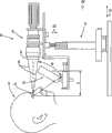
图4A和4B示意了示范性光源和成像装置,以方便讨论泪液膜的照射和对泪液膜镜面反射光的干涉交互的捕捉;Figures 4A and 4B illustrate exemplary light sources and imaging devices to facilitate discussion of tear film illumination and capture of interference interactions of tear film specularly reflected light;
图5示意了(在显微切片视图中)示范性泪液膜层,以示意光线如何能从不同的泪液膜层过渡面进行镜面反射;Figure 5 illustrates (in a microsection view) an exemplary tear film layer to illustrate how light can be specularly reflected from different tear film layer transitions;
图6是示范性处理的流程图,该处理用于从代表从泪液膜镜面反射的光的泪液膜的已经去除或基本去除了背景信号的图像得到一个或多个干涉信号;6 is a flowchart of an exemplary process for obtaining one or more interference signals from an image of a tear film representing light specularly reflected from the tear film from which background signal has been removed or substantially removed;
图7示意了聚焦在泪液膜脂质层上并捕捉了来自泪液膜的关注地方或区域的镜面反射光的干涉交互的第一图像;Figure 7 illustrates a first image of the interference interaction of specularly reflected light focused on the tear film lipid layer and capturing a place or region of interest from the tear film;
图8示意了聚焦在图7中泪液膜的脂质层上且捕捉了未被光源照射时的背景信号的第二图像;Figure 8 illustrates a second image focused on the lipid layer of the tear film in Figure 7 and capturing the background signal when not illuminated by a light source;
图9示意了图8的第二图像中捕捉的背景信号从图7的第一图像中被减去的泪液膜的图像;Figure 9 illustrates an image of the tear film with the background signal captured in the second image of Figure 8 subtracted from the first image of Figure 7;
图10是另一个示范性光学瓦面处理的流程图,该处理用于从代表来自泪液膜的镜面反射光的泪液膜关注地方或区域中的犹如砖瓦覆盖的部分中得到一个或多个干涉信号,其中已去除或基本去除了背景信号;10 is a flow diagram of another exemplary optical tile process for deriving one or more interferences from a tile-like portion of a tear film location or region of interest representing specularly reflected light from the tear film. signal, wherein the background signal has been removed or substantially removed;
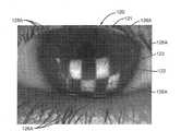
图11A示意了聚焦在泪液膜的脂质层上的第一图像,其捕捉了来自泪液膜关注地方或区域中的犹如砖瓦覆盖的部分的背景信号和镜面反射光的干涉交互;Figure 11A illustrates a first image focused on the lipid layer of the tear film, which captures the interference interaction of background signal and specular light from a tile-covered portion of the tear film in a place or region of interest;
图11B示意了聚焦在图11A的泪液膜的脂质层上的第二图像,其分别捕捉了图11A的关注地方或区域中的犹如砖瓦覆盖的部分中的镜面反射光和背景信号的干涉交互;FIG. 11B illustrates a second image focused on the lipid layer of the tear film of FIG. 11A , which respectively captures the interference of specularly reflected light and background signal in the tile-covered portion of the place or region of interest of FIG. 11A interact;
图12示意了图11A和11B的第一及第二图像的中的漫射光照射的犹如砖瓦覆盖的部分中所捕捉的背景信号被从图11A和11B的第一及第二图像中的对应的犹如砖瓦覆盖的部分的镜面反射光中减去或基本减去时的图像;Fig. 12 illustrates the background signal captured in the diffusely illuminated portion of the first and second images of Figs. The image when subtracted or substantially subtracted from the specular light of the tile-like portion of ;
图13A示意了聚焦在泪液膜的脂质层上的第一图像,其捕捉了来自泪液膜关注地方或区域中的同心的犹如砖瓦覆盖的部分的背景信号和镜面反射光的干涉交互;Figure 13A illustrates a first image focused on the lipid layer of the tear film, which captures the interference interaction of background signal and specularly reflected light from concentric, tile-covered portions of the tear film in places or regions of interest;
图13B示意了聚焦在图13A的泪液膜脂质层上的第二图像,其从图13A的泪液膜的关注地方或区域中的同心犹如砖瓦覆盖的部分中分别捕捉了镜面反射光和背景信号的干涉交互;Figure 13B illustrates a second image focused on the lipid layer of the tear film of Figure 13A, which captures specular light and background, respectively, from concentric tile-covered sections in the place or region of interest of the tear film of Figure 13A Interference interaction of signals;
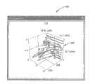
图14是示范性眼表干涉(OSI)装置的透视图,该装置用于照射并成像患者的泪液膜、显示图像、分析患者的泪液膜、并根据患者泪液膜的分析生成结果;14 is a perspective view of an exemplary ocular surface interference (OSI) device for illuminating and imaging a patient's tear film, displaying the image, analyzing the patient's tear film, and generating results based on the analysis of the patient's tear film;
图15是图14的OSI装置的侧视图,该装置照射并成像患者的眼睛和泪液膜;15 is a side view of the OSI device of FIG. 14 illuminating and imaging the patient's eye and tear film;
图16是成像患者眼睛和泪液膜的图14中的OSI装置内的摄像机和照明设备的侧视图;16 is a side view of the camera and lighting within the OSI device of FIG. 14 imaging the patient's eye and tear film;
图17是设置在图14的OSI装置中的照射装置的顶视图,该照明装置照射患者的泪液膜,其中摄像机捕捉患者的泪液膜的图像;17 is a top view of an illumination device disposed in the OSI device of FIG. 14, the illumination device illuminating a patient's tear film, wherein a camera captures an image of the patient's tear film;
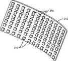
图18是示范性印刷电路板(PCB)的透视图,其中在图14的OSI装置的照射装置中设置了多个发光二级管(LED)以照射患者的泪液膜;18 is a perspective view of an exemplary printed circuit board (PCB) in which a plurality of light emitting diodes (LEDs) are disposed in the illumination device of the OSI device of FIG. 14 to illuminate the patient's tear film;
图19是图14的OSI装置的照射装置和壳体的透视图;19 is a perspective view of the illumination device and housing of the OSI device of FIG. 14;
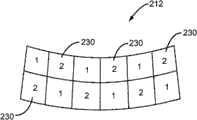
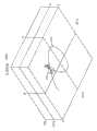
图20-24示意了用于图17的照射装置的示范性光线分组模型,其可用于对来自泪液膜的镜面反射光的犹如砖瓦覆盖的图案进行成像;20-24 illustrate exemplary ray grouping models for the illumination device of FIG. 17 that can be used to image a tile-like pattern of specularly reflected light from a tear film;
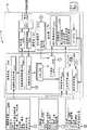
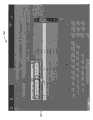
图25A示意了图14的OSI装置中的控制系统和支撑部件的示范性系统结构图;25A illustrates an exemplary system structure diagram of a control system and support components in the OSI device of FIG. 14;
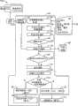
图25B是一个流程图,示意了图14的OSI装置的示范性总体处理流程,该装置具有根据图25A中的OSI装置的示范性系统结构图的系统部件;FIG. 25B is a flowchart illustrating an exemplary overall processing flow of the OSI apparatus of FIG. 14 having system components according to the exemplary system architecture diagram of the OSI apparatus of FIG. 25A;
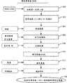
图26是一个流程图,示意了测量泪液膜层厚度(TFLT)之前在组合的患者泪液膜的第一及第二图像上进行的示范性预处理步骤;26 is a flowchart illustrating exemplary preprocessing steps performed on the combined first and second images of the patient's tear film prior to measuring the tear film layer thickness (TFLT);
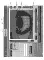
图27是一个示范性图形用户界面(GUI),其用于控制图14的OSI装置的成像、预处理和后处理设置;Figure 27 is an exemplary graphical user interface (GUI) for controlling the imaging, pre-processing and post-processing settings of the OSI device of Figure 14;
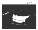
图28示意了泪液膜关注地方或区域中已减影图像的例子,其包含覆盖在泪液膜背景图像上的来自泪液膜的镜面反射光;Figure 28 illustrates an example of a subtracted image of a place or region of interest in a tear film comprising specular light from the tear film overlaid on a background image of the tear film;
图29A和29B示意了示范性的阈值掩模,其可用于在预处理包含来自患者泪液膜的镜面反射光的最终得到的图像时提供阀值功能;29A and 29B illustrate exemplary threshold masks that may be used to provide a threshold function when preprocessing the resulting image containing specularly reflected light from the patient's tear film;
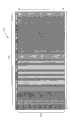
图30示意了图28的在已被进行预处理功能后的示范性图像,其留下了来自患者泪液膜的镜面反射光的干涉;Figure 30 illustrates the exemplary image of Figure 28 after it has been subjected to a pre-processing function that leaves interference from specular light from the patient's tear film;
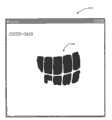
图31示意了图30的图像在已被执行了侵蚀和扩大预处理功能后的示范性图像;Figure 31 illustrates an exemplary image of the image of Figure 30 after erosion and dilation pre-processing functions have been performed;
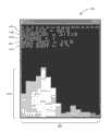
图32示意了示范性的直方图,其用于在所捕捉的泪液膜图像或帧中检测眨眼和/或眼睛运动;FIG. 32 illustrates an exemplary histogram for detecting blinks and/or eye movements in captured tear film images or frames;
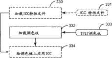
图33示意了将国际色彩协会(ICC)特性文件和泪液膜干涉模型载入图14的OSI装置的示范性处理;33 illustrates an exemplary process of loading an International Color Consortium (ICC) profile and a tear film interference model into the OSI device of FIG. 14;
图34示意了提供示范性可视化系统处理以便在图14的OSI装置中的显示器上显示患者泪液膜的图像的流程;34 schematically illustrates a flow for providing an exemplary visualization system process for displaying an image of a patient's tear film on a display in the OSI device of FIG. 14;
图35A-35C示意了患者泪液膜的示范性图像,其带有显示在显示器上的来自泪液膜的镜面反射光的干涉交互的犹如砖瓦覆盖的图像;35A-35C illustrate exemplary images of a patient's tear film with an interferometric interaction of specularly reflected light from the tear film displayed on a display as if a tile-covered image;
图36示意了可设置在图14的OSI装置中的示范性后处理系统;Figure 36 illustrates an exemplary aftertreatment system that may be provided in the OSI device of Figure 14;
图37A示意了示范性3-波泪液膜干涉模型,其基于3-波理论泪液膜模型以便将观测到的不同干涉颜色与不同脂质层厚度(LLTs)及水样层厚度(ALTs)关联起来;Figure 37A illustrates an exemplary 3-wave tear film interference model based on a 3-wave theoretical tear film model in order to correlate the observed different interference colors with different lipid layer thicknesses (LLTs) and aqueous layer thicknesses (ALTs) ;
图37B示意了另一个示范性3-波泪液膜干涉模型,其基于3-波理论泪液膜模型以便将观测到的不同干涉颜色与不同脂质层厚度(LLTs)及水样层厚度(ALTs)关联起来;Figure 37B illustrates another exemplary 3-wave tear film interference model based on the 3-wave theoretical tear film model in order to correlate the observed different interference colors with different lipid layer thicknesses (LLTs) and aqueous layer thicknesses (ALTs) link up;
图38是图37的3-波泪液膜干涉模型的另一种表示,其中对各红-绿-蓝(RGB)颜色值被分别应用了归一化;FIG. 38 is another representation of the 3-wave tear film interference model of FIG. 37 with normalization applied separately to each red-green-blue (RGB) color value;
图39是示范性的直方图,显示了从患者泪液膜所镜面反射的光的干涉信号的干涉交互与图37和图38的3-波泪液膜干涉模型的比较结果,以用于测量患者泪液膜的TFLT;39 is an exemplary histogram showing the interference interaction of the interference signal of light specularly reflected from a patient's tear film compared to the 3-wave tear film interference model of FIGS. 37 and 38 for measuring patient tear fluid TFLT of the membrane;
图40是来自患者的泪液膜的镜面反射光的干涉信号的干涉交互的RGB颜色表示和图37和38的3-波泪液膜干涉模型中的距离最小的RGB颜色值之间的像素距离的示范性直方图;Figure 40 is an RGB color representation of the interferometric interaction of the interference signal from the specularly reflected light of the patient's tear film and an illustration of the pixel distance between the minimum-distance RGB color values in the 3-wave tear film interference model of Figures 37 and 38 sex histogram;
图41是在预处理泪液膜图像时使用的示范性阀值掩模;Figure 41 is an exemplary threshold mask used in preprocessing tear film images;
图42是患者泪液膜的测量的LLT和ALT厚度的示范性的三维(3D)表面图;Figure 42 is an exemplary three-dimensional (3D) surface plot of measured LLT and ALT thickness of a patient's tear film;
图43是表示来自患者泪液膜结果窗口的镜面反射光的干涉交互的示范性图像,其基于用图38的归一化的3-波泪液膜干涉模型中的最匹配的RGB颜色值来代替泪液膜图像中的像素;43 is an exemplary image representing the interference interaction of specular light from a patient's tear film results window, based on replacing tear fluid with best-matching RGB color values in the normalized 3-wave tear film interference model of FIG. 38 pixels in the membrane image;
图44是三维(3D)空间中对于给定ALT的LLT的TFLT调色板的以RGB空间绘制的示范性TFLT调色板曲线;FIG. 44 is an exemplary TFLT palette curve plotted in RGB space for a TFLT palette of an LLT for a given ALT in three-dimensional (3D) space;
图45是三维(3D)空间中对于给定ALT的以RGB空间绘制用于图44的TFLT调色板的示范性TFLT调色板曲线,其中,LLT限定为240nm的最大LLT;Figure 45 is an exemplary TFLT palette curve for the TFLT palette of Figure 44 plotted in RGB space for a given ALT in three-dimensional (3D) space, where the LLT is defined as a maximum LLT of 240 nm;
图46示意了图45的TFLT调色板曲线,其中,显示了确定具有对应于模糊LLT的RGB值泪液膜像素值的可接受的到调色板的距离(ADP)滤波器;Fig. 46 illustrates the TFLT palette curve of Fig. 45, wherein an acceptable distance to palette (ADP) filter for determining tear film pixel values having RGB values corresponding to blurred LLTs is shown;
图47是用户界面系统的示范性登录屏幕,用以控制和访问图14的OSI装置;Figure 47 is an exemplary login screen of the user interface system for controlling and accessing the OSI device of Figure 14;
图48是示意了图14的OSI装置中的患者数据库界面的示范性接口屏幕;48 is an exemplary interface screen illustrating a patient database interface in the OSI device of FIG. 14;
图49示意了患者操作控制框,其用于选择捕捉患者数据库中的患者的新泪液膜图像或者查看来自图14的OSI装置中的该患者以前捕捉的图像;Figure 49 illustrates a patient operation control box for selecting to capture a new tear film image of a patient in the patient database or to view a previously captured image of that patient from the OSI device of Figure 14;
图50显示了用于查看由图14的OSI装置实时捕捉的或先前捕捉的患者泪液膜的查看界面;Figure 50 shows a viewing interface for viewing a patient's tear film captured in real time or previously captured by the OSI device of Figure 14;
图51示意了患者的泪液膜图像数据库;Figure 51 illustrates a patient's tear film image database;
图52示意了查看图像GUI屏幕,其并排显示了来自患者左眼及右眼两者的患者眼睛的图像上方的患者泪液膜的镜面反射光的干涉信号的干涉交互的重叠图像;Figure 52 illustrates a View Image GUI screen showing side-by-side overlaid images of the interferometric interaction of the interference signal of specularly reflected light from the patient's tear film above images of the patient's eyes from both the patient's left and right eyes;
图53示意了图52的GUI屏幕,其中,对患者的眼睛图像进行切换,从而只显示来自患者泪液膜的镜面反射光的干涉信号的干涉交互。Fig. 53 illustrates the GUI screen of Fig. 52 with the image of the patient's eye switched to show only the interference interaction of the interference signal from the specularly reflected light of the patient's tear film.
具体实施例specific embodiment
下面论述的实施例代表了能使本领域技术人员实施本发明的必要信息,并且示意性地说明了实现本发明的最佳方式。在根据附图阅读以下描述之后,本领域技术人员会理解发明的概念并认识到这些概念的应用并不特别限定于本文所描述的。应该理解的是,这些概念和应用落入本公开和所附权利要求书的范围内。The embodiments discussed below represent the necessary information to enable one skilled in the art to practice the invention, and illustrate schematically the best mode of carrying out the invention. After reading the following description in light of the accompanying drawing figures, those skilled in the art will understand the inventive concepts and recognize applications of these concepts not particularly limited to those described herein. It should be understood that these concepts and applications fall within the scope of the disclosure and the appended claims.
实施例的具体描述包含眼表干涉测量(OSI)装置、系统和测量患者眼睛泪液膜中的泪液膜层厚度(TFLT)的方法。该OSI装置,系统和方法可以用来测量眼睛泪液膜的脂质层部分的厚度(LLT)和/或水样层部分的厚度(ALT)。此处使用的“TFLT”包括LLT、ALT,或者LLT与ALT两者。此处使用的“测量TFLT”包括测量LLT、ALT,或者LLT与ALT两者。测量TFLT可以用在对患者泪液膜的诊断中,包括但不限于脂质层和水样层不足。这些特性可能是患者经历干眼病症状(DES)的原因或促使因素。The detailed description of the embodiments includes an ocular surface interferometry (OSI) device, system, and method for measuring tear film layer thickness (TFLT) in the tear film of a patient's eye. The OSI device, system and method can be used to measure the thickness (LLT) and/or the thickness (ALT) of the lipid layer portion of the tear film of the eye. "TFLT" as used herein includes LLT, ALT, or both LLT and ALT. As used herein, "measuring TFLT" includes measuring LLT, ALT, or both LLT and ALT. Measuring TFLT can be used in the diagnosis of a patient's tear film, including but not limited to lipid and aqueous layer deficiencies. These properties may be the cause or contributory factor for patients to experience dry eye symptoms (DES).
在这点,这里公开的实施例包括光源,将其控制为将可见区域中的光导向眼睛泪液膜。例如,光源可以是郎伯发射器,其在所有的发射方向提供均匀或者基本均匀的强度。光源被布置成保证光源发射的光线从泪液膜镜面反射到成像装置,并在眼睛泪液膜中经受相长干涉交互及相消干涉交互。成像装置聚焦在泪液膜的脂质层的关注区域(一个或多个)上,该成像装置具有检测光源频谱的频谱检测。成像装置捕捉从被照射的泪液膜所镜面反射的光线的干涉交互(即,调制)的第一图像,这些光线由于成像装置的聚焦效应而聚集在一起。然后,成像装置捕捉表示从泪液膜所镜面反射的光的干涉交互的干涉信号。成像装置产生代表第一图像中的干涉信号的输出信号(一个或多个)。第一图像可包含由成像装置对于脂质层的一个给定图像像素或多个给定图像像素的干涉信号。可对输出信号(一个或多个)进行处理和分析,以便对眼睛泪液膜的关注地方或区域中的TFLT进行测量。In this regard, embodiments disclosed herein include a light source that is controlled to direct light in the visible region toward the tear film of the eye. For example, the light source may be a Lambertian emitter, which provides a uniform or substantially uniform intensity in all directions of emission. The light source is arranged to ensure that light emitted by the light source is specularly reflected from the tear film to the imaging device and undergoes constructive and destructive interference interactions in the tear film of the eye. An imaging device is focused on the region(s) of interest in the lipid layer of the tear film, the imaging device having spectral detection that detects the spectrum of the light source. The imaging device captures a first image of the interference interaction (ie, modulation) of light rays specularly reflected from the illuminated tear film, which rays are brought together due to the focusing effect of the imaging device. The imaging device then captures an interference signal representing the interference interaction of light specularly reflected from the tear film. The imaging device produces output signal(s) representative of the interference signal in the first image. The first image may comprise the interference signal by the imaging device for a given image pixel or a plurality of given image pixels of the lipid layer. The output signal(s) can be processed and analyzed to measure TFLT in places or regions of interest in the tear film of the eye.
在这点上,图4A-9示意了眼表干涉测量(OSI)装置30的一般实施例。其他实施例将在本申请的后面部分描述。一般而言,将OSI装置30配置成照射患者的眼睛泪液膜、捕捉从眼睛泪液膜所镜面反射的光的干涉交互的图像、并且处理和分析这些干涉交互来测量TFLT。如图4A所示,侧视的位于一个患者眼睛30的前方的示范性OSI设备30被示出。图4B示意了在OSI装置30前面的患者34的顶视图。患者眼睛32的眼睛泪液膜由光源36(这里也称为“照明设备36”)照射,并且包括具有在可视区足以用于TLFT测量并且与干眼相关联的光谱的较大面积的光源。照明设备36可以是白色或者多波长光源。In this regard, a general embodiment of an ocular surface interferometry (OSI)
在该实施例中,照明设备36是一个郎伯发射器,其适于安放在支架38上面,并置于眼睛32的前方。正如这里所采用的,术语“郎伯表面”和“郎伯发射器”被定义为光发射器,其在所有的方向上具有相等或者基本相等的(也可以称为一致或者基本一致)的强度。这允许对一致或基本一致亮的泪液膜区域进行成像用于TFLT,如本公开中更加详细讨论的那样。照明设备36包含一个大表面积的发射器,其被设置成使得从发射器发射的光线可以从眼睛泪液膜被镜面反射,并且在其内的泪液膜层中经过相长和相消干涉。患者34的脂质层的图像是在其上可以看到干涉图像的背景而且它应该尽可能地在空间上一致。In this embodiment, the
成像装置40被包括在OSI装置30中,并且在患者34的眼睛泪液膜被照明设备36照射的时候,用于捕捉从患者34的眼睛泪液膜所镜面反射的光的干涉交互。成像装置40可以是照相机或摄像机、或者是捕捉图像并输出表示所捕捉图像的信息的输出信号的其他装置。输出信号可以是所捕捉图像的数字表示。照明设备36的几何结构可以理解为从成像装置40的成像镜头42开始,向前延伸到眼睛32,然后到照明设备36。光线跟踪的基本方程是Snell定律,其如下:
n1SinΘ1=n2SinΘ2n1SinΘ1 =n2SinΘ2
其中,“n1”和“n2”为包含光线的两种介质的折射系数,而Θ1和Θ2为光线相对于过渡表面垂线的角度。如图5中所示,照明设备36将光线44引导到眼睛泪液膜46。在镜面反射光48没有进入脂质层50反而从脂质层50前表面52反射的情况下,Snell定律简化为Θ1=Θ2,这是因为折射系数没有改变(也就是在两种情况下介质都是空气)。在这些情况下,Snell定律简化为典型的反射定律,使得入射角的角度等于反射角并且与反射角相反。where "n1" and "n2" are the refractive indices of the two media containing the light rays, andΘ1 andΘ2 are the angles of the light rays relative to the normal to the transition surface. As shown in FIG. 5 ,
一部分光线54穿过脂质层50的前表面52并进入脂质层50,如图5所示。因此,根据Snell定律,这些光线54与脂质层50前表面52垂直的角度(即Θ3)与光射线44的角度(Θ1)是不同的。这是因为脂质层50的折射系数和空气的折射系数不一样。穿过脂质层50的部分光射线54将被从脂质层到水样层的过渡面(transition)56镜面反射,从而产生镜面反射光线58。镜面反射光射线48、58在脂质层50前面经历相长和相消干涉。当镜面反射光射线48、58聚焦在脂质层50的前表面52上时,成像装置40收集叠加在脂质层50的前表面52上的镜面反射光射线48、58的干涉的调制。在脂质层50的前表面52上聚焦成像装置40允许在前表面52的平面处捕捉调制的干涉信息。这样,如果需要,所捕捉的干涉信息和根据干涉信息后来计算的TFLT可以在空间上和泪液膜46的特定区域配准,因为所计算的TFLT可以和这种特定区域相关联。A portion of the light rays 54 pass through the
脂质层50的厚度(‘d1’)是镜面反射光射线48,58之间的干涉交互的函数。脂质层50的厚度(‘d1’)是按光源30的时间(或纵轴)相干性的比例。因此,由光源30发射的可见光的一个波长比例的薄脂质层膜在其由摄像机或人眼观察时,提供来自镜面反射光的干涉的可检测的颜色。作为在干涉信号上所进行的且被表示为包含但不限于RGB色彩空间里的红-绿-蓝(RGB)值的数值的计算的结果,这些颜色是可检测的。镜面反射光的干涉的量化可以用于测量LLT。利用相同的原理还可以确定水样层60的厚度(‘d2’)。穿过脂质层50的部分光射线54(未显示)也可穿过脂质层-到-水样层的过渡面56,并且进入从水样层-到-粘液/角膜层的过渡面62进行镜面反射的水样层60。这些镜面反射同样会经历与镜面反射光射线48、58的干涉。根据菲涅尔(Fresnel)方程,从各过渡面的反射的量值取决于材料的折射系数以及入射的角度,并且因此干涉交互调制的深度也取决于这些参数,因此这就是最后得到的(resulting)颜色。The thickness ('d1') of the
返回图4A和4B,该实施例中的照明设备36是一个覆盖了约400nm到约700nm之间的可见范围的宽频谱的的光源。照明设备36包括拱形或弧形外壳64(参见图4B),单一光的发射器被安装到该外壳内,从而从眼睛32的视轴形成大约130度的对弧(subtend)角(参见图4B)。曲面可呈现更好的均匀性并更有效,因为几何形状产生用以生成给定光强的更小装置。从照明设备36所辐射的总的功率应该保持为最小以防止泪液的加速蒸发。进入瞳孔的光线可导致反射撕裂(reflex tearing)、斜视、及其他视觉上的不舒服,所有这些都会影响TFLT的测量精度。Returning to Figures 4A and 4B, the
为了防止本体感觉的变化并减少泪液膜46的发热,眼睛32上的入射功率和强度应该最小,并因此可由成像装置40执行收集及聚焦镜面反射光的步骤。成像装置40可以是摄像机、裂隙灯显微镜,或安装在架子38上的其他观测仪器,如图4A和4B所示。泪液膜46的图像模式的具体可视化涉及收集镜面反射光66及在脂质层52处聚该焦镜面反射光,从而使得从眼睛泪液膜所镜面反射的光的干涉交互是可观测的。To prevent changes in proprioception and reduce heating of the
按照图4A和4B中的OSI装置30的背景,图6示意了一个流程图,其讨论OSI装置30如何可用来获取从泪液膜46所镜面反射的光的干涉交互,该干涉可以用于测量TFLT。在讨论TFLT测量之前,首先获得从泪液膜46所镜面反射的光的干涉交互并对其进行讨论。在图6显示的该实施例中,该过程开始于相对于照明设备36和成像装置40调整患者32(块70)。控制照明设备36照射患者34的泪液膜46。将成像设备40控制成聚焦在脂质层50的前面板52上使得从泪液膜46所镜面反射的光的干涉交互被收集并可观测。其后,照明设备36照射患者34的泪液膜46(块72)。In the context of the
然后控制成像装置40并将其聚焦在脂质层50上,以便在第一图像中收集由于以照明设备36照射泪液膜而从泪液膜上的关注区域或地方镜面反射的光(图6,块74)。图7中给出了由照明设备36所得到的第一图像的例子。如在其中所示意的,展现了已经被照明设备36照射的患者眼睛80的第一图像79。可以控制照明设备36和成像装置40来照射泪液膜82上不包括眼睛80的瞳孔83的关注区域或地方,以便降低反射撕裂。反射撕裂将暂时引起水样层和脂质层增厚,从而暂时改变从泪液膜82所镜面反射的光的干涉信号。如图7所示,当成像装置40聚焦在泪液膜82的脂质层88的前表面层86上时,作为由照明设备36的照射结果而从泪液膜82被镜面反射的光的干涉信号的干涉交互85在第一图像79的关注地方或区域81中被捕捉。作为出现在从泪液膜82所镜面反射的光的干涉中的波长的结果,干涉交互85对人类观测者表现为带颜色的图案。
然而,在第一图像79中背景信号同样被捕捉。背景信号被添加到关注地方或区域81中的镜面反射光,并且也被包括在关注地方或区域81以外。背景信号不是从泪液膜82镜面反射的光,因此不含干涉信息。背景信号可包含进入成像装置40的杂散(stray)和环境光,从患者34的脸、眼皮、和/或者泪液膜82外侧及下面的眼睛80结构散射的光,以及泪液膜82下的结构的图像,其中该散射的光是由于杂散光、环境光和照明设备36的漫射光照射产生的。例如,第一图像79包含眼睛80中泪液膜82下面的虹膜。背景信号给所捕捉的从泪液膜82镜面反射的光的干涉添加了偏(即,偏移)差,从而降低了它的信号强度和对比度。此外,如果背景信号具有不同于光源的光的色调,则第一图像79中从泪液膜82所镜面反射的光的干涉也可能出现色移。成像装置40产生表示在第一图像79中捕捉到的光线的第一输出信号。由于第一图像79包含来自于镜面反射光的光线以及背景信号,因此成像装置40从第一图像79产生的第一输出信号将包含表示所捕捉到的从泪液膜82所镜面反射的光的干涉且具有由背景信号引起的偏(即,偏移)差的干涉信号。因此,作为背景信号偏(即偏移)差的结果,被分析以便测量TFLT的第一输出信号可包含误差。However, background signals are also captured in the first image 79 . A background signal is added to the specularly reflected light in the place or region of
因此,在该实施例中,在对由于第一图像79而由成像装置40产生的第一输出信号进行分析以测量TFLT之前,对该信号进行处理以便从干涉信号中减去或者基本减去背景信号,从而减少误差。这也被称为“背景减影(subtraction)”。背景减影是把不需要的反射从图像中去除的过程。在这点上,成像装置40被控制以在泪液膜82未被照明设备36照射时捕捉泪液膜82的第二图像90,如图8中的例子所示。应该使用与捕捉第一图像79时相同的成像装置40的设置和焦点来捕捉第二图像90,这样第一图像79和第二图像90形成了在彼此的短时间内所捕捉的相应的图像对。成像装置40生成第二输出信号,该信号包含出现在第一图像79中的背景信号(图6中的块76)。为了从第一输出信号中消除或减少该背景信号,将第二输出信号从第一输出信号中减去以便产生最终得到的信号(图6中的块77)。表示在该实施例中的最终得到的信号的图像作为最终得到的图像92示意在图9中。因此,在这个例子中,背景减影涉及两幅图像79、90,以便提供在其中两幅图像79、90彼此相减的帧对,这样就保留了来自泪液膜82的镜面反射,并且同时来自于虹膜和其他区域的漫反射被整个或部分去除。Thus, in this embodiment, prior to analyzing the first output signal produced by the
如图9所示,最终得到的图像92包含从泪液膜82镜面反射的光的隔离干涉94的图像,其中,已经消除或者减少了背景信号(图6中的块78)。这样,最终得到的信号(表示图9的结果图像92)包括了干涉信号,该干涉信号具有在泪液膜82上的关注区域或地方81中的改善了纯度和对比度的信号。正如本申请稍后将讨论的,最终得到的信号对来自于从泪液膜82的所镜面反射的干涉信号的干涉交互,提供精确分析,以反过来精确测量TFLT。可以采用任何获取泪液膜82的第一和第二图像并从第一图像79中减影第二图像90中的背景信号的方法或装置。在本申请的整个剩下部分讨论其他具体实施例。As shown in FIG. 9 , the resulting
在减影之前,在第一图像(一个或多个)79和第二图像(一个或多个)90之间执行可选的配准功能(registration function),以确保要从第一图像(一个或多个)79中减去的第二图像(一个或多个)90中的部位或点是第一图像79(一个或多个)上的相同或相应的部位或点。例如,从第一和第二图像79、90提取一系列相似点,以便计算两幅图像间的刚性转换矩阵。该转换矩阵允许一个图像上的一个点(如x1,y1)被转换成其它图像上的等同二维(2D)图像(如x2,y2)。例如,在这方面可以使用Matlab
值得注意的是,虽然这个例子讨论成像装置40所捕捉的第一图像和第二图像以及所得到的第一输出信号和第二输出信号,第一图像和第二图像可包括按时间顺序取得的多个图像。如果成像装置40是摄像机,则第一图像和第二图像可包含许多时间连续的帧,这些帧由成像装置40的帧速率来控制。成像装置40生成一系列第一输出信号和第二输出信号。如果捕捉了不止一个图像,则理想地,在第一图像中所进行的减影应是从在第一图像之后马上得到的第二图像中,使得相同或者基本相同的照明条件存在于图像之间,因此第二图像中的背景信号出现在第一图像中。从第一输出信号中减去第二输出信号可以实时进行。可替代地,第一和第二输出信号可以被记录并在之后进行处理。照明设备36可以被控制以快速时断时续地振荡从而第一和第二图像可被获得,并且在少于一秒的时间内进行从第一输出信号内减去第二输出信号。例如,如果照明设备36以30Hz的频率振荡在开和关之间,则成像装置40可以每秒60帧(fps)的同步捕捉泪液膜46的图像。在这点上,在一秒内可以获得三十(30)幅第一图像和三十(30)幅第二图像,其中依次获取每对第一和第二图像。It is worth noting that while this example discusses the first and second images captured by imaging
捕捉镜面反射光的干涉以及生成并处理包含干涉信号的最后得到的信号之后,可以对照泪液膜层干涉模型比较其干涉信号或表示以测量TFLT。通过成像装置,可以将干涉信号进行处理并转化成数字的红-绿-蓝(RGB)成分值,这个值可以和泪液膜干涉模型中的RGB成分值进行比较,从而测量泪液膜TFLT。泪液膜干涉模型是基于对不同LLT中的泪液膜的脂质层进行建模,并且基于在被光源照射时对从泪液膜模型所镜面反射的光的干涉信号中的最后得到的干涉交互进行表现。泪液膜干涉模型可以是理论泪液膜干涉模型,其中,对具体光源、具体成像装置以及泪液膜层进行数学建模,并且当模拟的光源照射利用模拟的成像装置记录模拟的泪液膜层时,记录用于不同LLTs的最后得到的干涉信号。应该将用于数学建模的光源和成像装置的设置复制在OSI装置30中所使用的照明设备36和成像装置40中。可替代地,泪液膜干涉模型可以基于包括物理虚泪液膜层的虚泪液膜模型,其中,采用真实光源照射虚泪液膜层模型,并且使用实际成像装置按照经验观测和记录表示镜面反射光的干涉的干涉信号中的交互干涉。After capturing the interference of the specular light and generating and processing the resulting signal containing the interference signal, its interference signal or representation can be compared against the tear film layer interference model to measure TFLT. Through the imaging device, the interference signal can be processed and converted into a digital red-green-blue (RGB) component value, which can be compared with the RGB component value in the tear film interference model to measure the tear film TFLT. The tear film interference model is based on modeling the lipid layer of the tear film in different LLTs and based on the representation of the resulting interference interaction in the interference signal of light specularly reflected from the tear film model when illuminated by a light source . The tear film interference model may be a theoretical tear film interference model in which a specific light source, a specific imaging device, and a tear film layer are mathematically modeled, and when the simulated light source illuminates the simulated tear film layer using a simulated imaging device, the recorded The resulting interference signal for different LLTs. The setup of the light source and imaging device used for the mathematical modeling should be replicated in the
在泪液膜干涉模型中可以将水样层模拟为具有无穷大、最小或者可变的厚度。如果水样层被模拟为具有无穷大的厚度,则泪液膜干涉模型假设从水样层-到-粘液层的过渡面62(参见图5)没有出现镜面反射。如果水样层62被模拟为具有某一最小的厚度(例如≥2μm),则可认为来自水样层-到-粘液层过渡面62的镜面反射对于干涉信号产生的卷积的(convolved)RGB信号的影响可以忽略。在任一情况中,泪液膜干涉模型仅假设并包括来自脂质层-到-水样层过渡面56的镜面反射。因此,这些泪液膜干涉模型实施例允许测试LLT而不考虑ALT。将干涉信号中的干涉交互和泪液膜干涉模型中的干涉交互进行比较从而测量LLT。The aqueous layer can be modeled in the tear film interference model as having infinite, minimal or variable thickness. If the aqueous layer is modeled as having an infinite thickness, the tear film interference model assumes that no specular reflection occurs at the aqueous-to-mucus layer transition surface 62 (see FIG. 5 ). If the
可替代地,如果水样层60被建模成具有可变的厚度,则泪液膜干涉模型还包括干涉交互中的来自水样层-到-粘液层过渡面62的镜面反射。因此,泪液膜干涉模型将包括由对应于不同LLT和ALT组合的干涉交互组成的二维数据。来自干涉信号的干涉交互可以和泪液膜干涉模型中的干涉交互比较,以测量LLT和ALT两者。关于具体泪液膜干涉模型的更多信息将在本申请的后面部分进行描述。Alternatively, if the
在以上描述的图6-9的实施例中,包含背景信号的泪液膜82的第二图像90在泪液膜82未被照明设备36照射时捕捉。只有环境光照射泪液膜82和下面的眼睛80结构。因此,第二图像90和由成像装置40从第二图像90产生的最后得到的第二输出信号不包括由于照明设备36的漫射光照射而从患者脸部及眼睛结构所散射的光引起的背景信号。只有由环境光引起的散射光被包括在第二图像90中。然而,因照明设备36的漫射光照射引起的散射光被包括在第一图像79的背景信号里,第一图像79包含从泪液膜82所镜面反射的光的干涉交互。此外,由于第一图像79是在照明设备36照射泪液膜时被捕捉的,因此在第一图像79中所捕捉到的泪液膜82下方的眼睛结构(包括虹膜)的强度比第二图像90中捕捉到的亮。因此,在这里描述的另一个实施例中,控制成像装置40以便在照明设备36倾斜照射泪液膜82时捕捉泪液膜82的第二图像。因此,所捕捉的第二图像还包括背景信号以及泪液膜82下方眼睛被直接照射的结构的更高强度的信号,该背景信号来自作为照明设备36漫射光照射的结果的散射光。因此,当第二输出信号被从第一输出信号减去时,更高强度的眼睛结构背景和表示照明设备36漫射光照射的散射光、以及背景光及杂散光的背景信号的分量被从最终得到的信号中减去或基本减去,从而进一步增加最终得到的信号中的干涉信号纯度和对比度。然后,可处理和分析最终得到的信号以测量TFLT,如本申请后面部分要详细描述的。In the embodiment of FIGS. 6-9 described above, the
在这点上,图10-12示意了用于照射和捕捉从泪液膜所镜面反射的光的干涉的实施例。在该实施例中,在照明设备36使用照明倾斜照射泪液膜时捕捉第二图像,所述照明具有与被用于产生从泪液膜所镜面反射的光相同或者几乎相同的平均的几何形状和照明水平。以这种方式,第二图像中所捕捉的背景信号包含出现在第一图像中的等同的背景信号,该第一图像包括由于照射设备36的漫射光照射的结果而从泪液膜及患者眼睛所散射的光。由于在捕捉第二图像时启动照明设备36时的相同照明,第二图像还包括表示泪液膜下的眼睛结构的信号。在该实施例中,对泪液膜提供了“犹如砖瓦覆盖的(tiled)”或者“瓦面(tiling)”式照射。瓦面允许光源对泪液膜上所关注的子区域(一个或多个)进行照射以获取镜面反射光而同时对邻近泪液膜的关注的子区域(一个或多个)进行漫射地照射以获取作为照明设备36的漫射光照射的结果的散射光。这样,所减去的背景信号包括作为照明设备36的漫射光照射结果的散射光,从而允许进一步降低偏移偏(即,偏移)差,并由此增加干涉信号的纯度和对比度。In this regard, FIGS. 10-12 illustrate an embodiment of interference for illuminating and capturing light specularly reflected from the tear film. In this embodiment, the second image is captured when
在这点上,如图10所示的,该过程从相对于照明设备36和成像装置40调整患者34开始(块100)。控制照明设备36照射患者34的泪液膜。将成像装置40适当放置并将其控制为聚焦在脂质层,使得在泪液膜被照射时,从泪液膜所镜面反射的光的干涉交互是可以观察的。其后,将照明设备36的照明图案控制为第一“瓦面”模式,以便从泪液膜的第一关注区域(一个或多个)产生镜面反射光,同时漫射地照射邻近的泪液膜的第二关注区域(一个或多个)(块102)。正如本申请后面会详细讨论的,将照明设备36控制成只打开照明设备36内的某些照明部件以便控制照明图案。In this regard, as shown in FIG. 10 , the process begins with adjusting the patient 34 relative to the
图11A以示例的方式示意了成像装置40在照明设备36以第一模式产生照明图案时所捕捉的患者眼睛121和泪液膜123的第一图像120的例子。在该例子中,控制照明设备36以在泪液膜123上的关注区域或地方122中提供第一犹如砖瓦覆盖的照射模式。当以第一模式照射泪液膜123时,成像装置40捕捉患者眼睛121和泪液膜123的第一图像120(块104)。如图11A所示,患者眼睛121的第一图像120已经被照射,从而在泪液膜123的关注区域或地方122的第一部分126A中产生镜面反射光。来自第一部分126A的干涉信号(一个或多个)包括来自与附加的背景信号一起的镜面反射光的干涉,该背景信号包括作为从来自照明设备36的漫射光照射的结果的散射光信号。再次,可以控制照明设备36和成像装置140照射不包括眼睛121瞳孔的泪液膜123,以减少反射撕裂。在块102中,照明设备36可以闪光,从而从第一部分126A产生镜面反射光,由此在块140中,成像装置40与照明设备36的闪光同步,以捕捉患者眼睛121和泪液膜123的第一图像120。11A illustrates, by way of example, an example of a
如图11A的第一图像120中所示,同样在第一模式期间,照明设备36的照明图案倾斜照射第二、与关注地方或区域122中的第一部分126A相邻的第二部分128A。第二部分128A包括在第一部分(一个或多个)126A中出现的可比较的背景偏移,其包括作为来自照明设备36的漫射光照射结果的散射光,这是因为成像装置40捕捉第一图像120时照明设备36是打开的。此外,由于照明设备36的漫射光照射,在第二部分128A中捕捉泪液膜123下方的眼睛121结构。这和图9的第二图像90是相反的,其中,获取第二图像90时因为照明设备36的漫射光照射没有被提供给泪液膜。因此,在该实施例中,泪液膜123的关注地方或区域122同时被分成两部分:产生与背景信号组合的镜面反射光的第一部分126A,和由照明设备36漫射光照射并包含背景信号的第二部分128A,该背景信号包括来自照明设备36的散射光。成像装置40生成第一输出信号,该信号包含了第一部分126A和第二部分128A的表示。As shown in the
接下来,以第二模式控制照明设备36,以便在照射泪液膜123时从第一模式翻转照明图案(图10的块106)。在第二模式的照射中捕捉泪液膜121的第二图像130,如图11B以示例方适所示意的(图10的块108)。如图11B中的第二图像130所示,图11A的第一图像120中的第二部分128A现在是图11B的第二图像130中的第二部分128B,其包含具有附加的背景信号的来自泪液膜123的镜面反射光。图11A的第一图像120中的第一部分126A现在是图11B的第二图像130中的第一部分126B,其包含背景信号而没有镜面反射光。再次地,第一部分126B中的背景信号包括由于照明设备36的漫射光照射而产生的散射光信号。在图11B中,成像装置40生成第二图像130的第二输出信号。在块106中,照明设备36也可闪光,从而从第二部分128B产生镜面反射光,由此成像装置40与块106中的照明设备36的闪光同步,以便捕捉患者眼睛121和泪液膜123的第二图像130。Next, the
随后可以将第一及第二输出信号相结合以生成最终得到的信号,其由从泪液膜123所镜面反射的光的干涉信号组成,其中,背景信号已经从该干涉信号中被减去或基本去除(图10的块110)。通过具有从泪液膜123的关注地方或区域122所镜面反射的光的具有已消除或减少了的背景信号干涉信息而生成最终得到的图像,其包括来自由照明设备36的漫射光照射的散射光引起的背景信号(图10的块112)。关于此的最终得到的图像132的例子示意在图12中。最终得到的图像132代表与由图11B中第二图像130表示的第二输出信号的相结合的由图11A中的第一图像120所表示的第一输出信号。如图12所示意的,从泪液膜123所镜面反射的光的干涉信号被提供给关注地方或区域122中的第一及第二部分126、128两者。背景信号已被消除或减少。正如图12中可以看到的,表示从泪液膜123的第一及第二部分126、128所镜面反射的光的干涉信号的信号纯度和对比度看起来比例如图9中的干涉交互94更鲜明、对比度更高。The first and second output signals may then be combined to generate a final signal consisting of an interference signal of light specularly reflected from the
在讨论前面图11A和图11B中的示例性第一及第二图像120、130时,可认为各第一部分126为第一图像,认为各第二部分128为第二图像。因此,当第一及第二部分126A、128B被与对应的第一及第二部分126B、128A相结合时,其类似于将第二部分126B、128A分别从第一部分12A、128B中去除。In discussing the exemplary first and
在图10-12的例子中,第一图像和第二图像120、130包含许多部分或者瓦(tile)。瓦的数目取决于提供给及选择给照明设备36以产生照射泪液膜123的第一及第二照射模式的照明交互的分辨率。照射模式可以从极端的一个瓦到期望的任意数量的瓦。各个瓦可以是成像装置40中的一个像素或者覆盖多于一个像素的区域的大小,这取决于照明设备36和成像装置40的性能。瓦的数目可影响表示从泪液膜镜面反射的光的干涉信号的精确度。在瓦图案中设置太少的瓦可能限制一般照明几何形状的代表性精确度,该几何形状在用于分别从部分128B和126A中精确去除的部分128A和126B中产生了由成像装置40所捕捉的散射光信号。In the example of Figures 10-12, the first and
值得注意的是,虽然图10-12中的例子讨论了成像装置40捕捉的第一图像和第二图像以及最终得到的第一输出信号和第二输出信号,第一图像和第二图像可包括按照时间顺序获取的多幅图像。如果成像装置40是摄像机,则第一和第二图像可包含许多时间连续的帧,这些帧由成像装置40的帧速率所控制。成像装置40生成一系列的第一输出信号和第二输出信号。如果捕捉了不止一个图像,则在第一图像中所进行的去除理想情况下是从第一图像之后马上获得的第二图像中,从而图像间存在相同或者基本相同的照明条件,因此第二图像中的背景信号出现在第一图像中,且更重要的是,这样在所去除的帧之间,眼睛的移动尤其是泪液膜动态的移动最小。将第二输出信号从第一输出信号中去除可以实时地进行。可替代地,第一和第二输出信号可以被记录并稍后再进行处理。It should be noted that although the examples in FIGS. 10-12 discuss the first and second images captured by imaging
除了图11A-12所示的“齿状”瓦面图案,其他光学瓦面图案也是可以的。图13A和13B通过显示眼睛140和泪液膜142的图像而示意了可替代的瓦面模式的实施例。在该实施例中,照射泪液膜142的照明设备36提供了同心的光学瓦面图案。从泪液膜142镜面反射的光的干涉交互被成像装置40捕捉。如图13A所示,在照明设备36的第一模式期间,获得具有泪液膜142上的关注地方或区域146的第一图像144。控制照明设备36在第一模式生成第一照明图案,使得泪液膜142的关注地方或区域146的中心部分148产生从泪液膜142镜面反射的光。连通背景信号一起,中心部分148包括从泪液膜142镜面反射的光,背景信号包括来自由照明设备36对泪液膜142进行漫射光照射的散射光信号。背景信号产生于关注地方或区域146的边缘部分152。成像装置40产生了代表图13A中第一图像144的第一输出信号。In addition to the "toothed" tile patterns shown in Figures 11A-12, other optical tile patterns are possible. 13A and 13B illustrate an alternative tile pattern embodiment by showing images of the
在照明设备36的第二模式中,如图13B的代表性的第二图像160所示的,控制照明设备36以便将照射泪液膜142的照明模式从第一模式进行反转。现在,镜面反射光从关注地方或区域146的边缘152产生,其包括附加的背景信号。现在中心部分148只产生背景信号。这样,中心部分148和边缘部分152是同中心的部分。成像装置140产生了代表图13B中第二图像160的第二输出信号。In the second mode of
随后,第一及第二输出信号被结合以生成最终得到的信号,其由从整个关注地方或区域146的泪液膜142所镜面反射的光的干涉信号组成,其中,背景信号已经从该干涉信号中去除或基本去除。通过具有来自从泪液膜142中的关注地方或区域146所镜面反射的光且其中背景信号已消除或减少的干涉信息可生成类似于图12的最终得到的图像(未显示),其包括由照明设备36的漫射光照射产生的散射光引起的背景信号。随后,处理并分析最终得到的图像以测量TFLT。在图13A和13B的例子中,将照明设备36控制在第一和第二模式使得中心部分148和边缘部分152之间区域的关系被平衡到大约50%/50%,从而在两种模式中,从照明设备36向泪液膜142不产生镜面反射光的部分提供相同的漫射光照射。然而,也可采用其它的平衡比例。Subsequently, the first and second output signals are combined to generate the resulting signal, which consists of an interference signal of light specularly reflected from the
可替代地,可以采用对眼睛泪液膜进行小范围的扫描来获得从泪液膜所镜面反射的光的干涉,从而在不从照明设备36提供犹如砖瓦覆盖的照射模式或散射光的情况下得到高信号强度和对比度的干涉信号。比如,成像在眼睛泪液膜上的关注地方或区域可以被做得非常小,小至成像装置40的最低分辨率(如一个像素)。这样,在被照射时,实际上没有从照明设备36向患者泪液膜上的的关注地方或区域提供任何漫射光照射。相对于图像中捕捉到的镜面反射光的水平,从泪液膜镜面反射的光的图像中所捕捉的背景信号是可以忽略的。因此,对多幅图像的去除不需要进行。控制照明设备36扫描泪液膜的期望部分以便连续捕捉图像,其中,每次扫描都捕捉从关注的小区域或小地方所镜面反射的光的图像。然后,组合各扫描图像以生成具有可忽略的背景信号的完整的从泪液膜镜面所反射的光的图像,并对该图像进行处理和分析以测量TFLT。Alternatively, a small scan of the tear film of the eye can be used to obtain the interference of light specularly reflected from the tear film, thereby obtaining Interferometric signals with high signal intensity and contrast. For example, the location or region of interest imaged on the tear film of the eye can be made very small, down to the lowest resolution of the imaging device 40 (eg, one pixel). Thus, when illuminated, virtually no diffuse light illumination is provided from the
示范性的OSI装置Exemplary OSI device
上面所讨论的示意性说明提供了对患者的TFLT进行照射和成像的示例。这些原理将被相对于示意在图14-50中的OSI装置170的具体示例而详细描述并且在本申请下文的整个剩余余部分进行描述。OSI装置170可照射患者的泪液膜,捕捉来自患者泪液膜的干涉信息,并且处理和分析干涉信息来测量TFLT。此外,OSI装置170包括多个可用于处理最终得到的信号中的干涉信号以增强TFLT测量的光学预处理部件。OSI装置170可包括显示器和用户界面,从而允许医生或技师控制OSI装置170以对患者的眼睛和泪液膜进行成像并且测量患者的TFLT。The schematic illustrations discussed above provide an example of illuminating and imaging a patient's TFLT. These principles will be described in detail with respect to the specific example of the
照射和成像Irradiation and Imaging
在这方面,图14图示了OSI装置170的透视图。OSI装置170设计为便于对患者的眼睛泪液膜进行成像以及对图像进行处理和分析,从而确定与患者的泪液膜有关的特征。在这点上,OSI装置170包括成像装置和光源,正如下文要详细描述的。如图14所示,OSI装置170一般由壳体172、监视器(“显示器”)174和患者头部支撑176组成。壳体172可设计成台式放置(table top placement)。壳体172以固定的关系搁在在底座178上。正如下文将详细讨论的,壳体172安放成像装置和其他电子设备、硬件和软件以允许医生对患者的眼睛泪液膜进行成像。光源173(在这里也称为“照明设备173”)也设置在壳体172中并且设置在半透明的散射窗175后面。半透明窗175可以是柔性的、白色的、半透明丙烯酸塑料片。In this regard, FIG. 14 illustrates a perspective view of an
为了对患者的眼睛泪液膜进行成像,患者将他或她的头部放在患者头部支撑176中,并且将他或她的下巴搁在颌托180上。可调节颌托180以使患者的眼睛和泪液膜与壳体172中的成像装置对准,正如下文要详细讨论的。颌托180可设计成支撑重达两(2)磅的重物,但这并不是一个限制因素。当患者头部放在患者头部支撑176中时,透明窗177允许壳体172中的成像装置对患者的眼睛和泪液膜有清晰的视线。OSI装置170设计为一次成像一只眼睛,但是如果需要,也可构造成成像患者的两只眼睛。To image the patient's eye tear film, the patient places his or her head in
通常,显示器174提供从OSI装置170的输入和输出。例如,可在显示器174上设置用户界面,以便医生操作OSI装置170并且与壳体172中所设置的控制OSI装置170运行的控制系统交互,OSI装置170包括成像装置、成像装置定位系统、光源、其他支持硬件和软件,以及其他部件。例如,用户界面可允许控制成像装置的成像定位、聚焦、以及成像装置的用于捕捉患者眼睛泪液膜图像的其他设置。控制系统可包括带有存储数据的存储器的通用微处理器或计算机,这些数据包括患者眼睛和泪液膜的图像。可选择微处理器,以提供足够的处理患者泪液膜图像的处理速度并产生关于该泪液膜的输出特性的信息(例如,一分钟每二十秒图像捕获)。控制系统可控制光源与成像装置的同时启动,以便在被适当照射时捕捉患者眼睛泪液膜上的关注区域的图像。可设置不同的输入和输出端口及其他装置,包括但不限于控制成像装置的操纵杆、USB端口、包括以太网通信的有线和无线通信、键盘、鼠标、扬声器(一个或多个)等。在壳体172中设置电源来为其内需要电力的部件供电。也可设置诸如风扇的冷却系统来从其内的热生成部件冷却OSI装置170。In general,
显示器174由控制系统驱动来提供与成像的患者泪液膜有关的信息,包括TFLT。显示器174还提供图形用户界面(GUI),以允许医生或其他用户控制OSI装置170。为了允许对患者泪液膜进行人工诊断,由壳体172中的成像装置所取得的患者眼睛泪液膜的图像也可显示在显示器174上,以便医生检查,正如下文图示及更加详细描述的。显示器174上显示的图像可以是成像装置获取的实时图像,或者可以是存储在存储器中的先前记录的图像。就生产而言,为了虑及不同方向的OSI装置170提供普遍的构造,显示器174可以绕底座178旋转。显示器174连接到绕底座178旋转的监控臂182,如所示的。如图14所示,如果医生需要直接坐在患者对面,显示器174可安装在患者头部支撑176的相反侧。可替代地,显示器174可绕要安在患者头部支撑176附近的X-轴向左或右旋转。显示器174可以是触摸屏监控器,以允许医生或其他用户直接经由显示器174的触摸给壳体172中的控制系统提供输入和控制,以控制OSI装置170。图14所示的显示器174为十五英寸(15”)平板液晶显示器(LCD)。然而,显示器174也可以设置为任意的类型或尺寸,包括但不限于阴极射线管(CRT)、等离子体、LED、OLED、投影系统等。
图15显示了图14的OSI装置170的侧视图,以进一步图示患者眼睛和眼睛泪液膜的成像。如在其中所示的,患者将其头部184放在患者头部支撑176中。更具体地,患者将其前额186倚着设置为患者头部支撑176一部分的头靠188。患者将其下巴190放在颌托180中。将患者头部支撑176设计为便于患者的眼睛192与OSI装置170对准,且特别地,与显示为设置在壳体172中的成像装置194(照明设备)对准。可将颌托180调高或调低以便相对于OSI装置170移动患者的眼睛192。FIG. 15 shows a side view of the
如图16所示,成像装置194用于对患者眼睛泪液膜进行成像以确定患者泪液膜的特性。具体地,成像装置194用于在光源196(在这里也称为“照明设备196”)照射时,捕捉从患者泪液膜镜面反射的光的干涉交互以及背景信号。正如先前所讨论的,当照明设备196照射或不照射患者泪液膜时,可捕捉背景信号。在OSI装置170中,成像装置194为“成像源”模型DFK21BU04电荷耦合器件(CCD)数字摄像机198,但也可设置多种类型的度量学相机或成像装置。CCD摄像机具有高效地光聚焦、线性行为、冷操作以及即时图像可用性的特征。线性成像装置是提供表现所捕捉图像的输出信号的装置,该输出信号与来自所捕捉图像的输入信号精确地成比例。因此,线性成像装置(例如,伽玛校正设置为1.0,或无伽玛校正)的使用提供了无失真的干涉数据,之后可利用线性分析模型来分析该干涉数据。这样,就不必在分析之前对所得到的泪液膜图像进行线性化,从而节省了处理时间。之后,可对所捕捉的线性图像添加伽玛校正,以便在OSI装置170中的非线性显示器174上人可察觉的显示。可替代地,可采用相反的情形。即,提供非线性成像装置或非线性设置来捕捉泪液膜图像,其中,可将表示干涉信号的干涉交互的非线性数据提供给非线性显示监控器,而无需对向医生显示的泪液膜图像进行处理。将非线性数据进行线性化以用于泪液膜处理和分析,从而估计泪液膜层的厚度。As shown in FIG. 16,
摄像机198能够形成患者眼睛的无损耗的完整动态视频图像。如图16所示,摄像机198具有由光线199之间的角度所限定的景深以及允许同时聚焦患者整个泪液膜的透镜焦距。摄像机198具有外触发器支架,从而控制系统可控制摄像机198来对患者眼睛进行成像。摄像机198包括安装在壳体172中的镜头。在该实施例中,摄像机198具有640×480像素的分辨率和能够高达每秒六十(60)帧(fps)的帧速率。摄像机198中采用的透镜系统将采样平面中大小为16×12mm的物体成像到摄像机198内的CCD检测器的有效区域上。作为例子,摄像机198可以是使用Pentax VS-LD25 Daitron 25-mm固定焦距镜头的DBK21AU04 Bayer VGA(640×480)摄像机。也可以采用具有可替代的像素尺寸和数量、可替代的镜头(等)的其他摄像机型号。
虽然在OSI装置170中设置了摄像机198,但是如果帧速率足够快能够生成高质量的患者眼睛图像的话,也可以使用静物摄相机。每秒多帧(fps)的高帧速率有助于从所捕捉的表示从患者泪液膜所镜面反射的光的干涉信号中高品质地去除背景信号,并且可以在捕捉图像时提供更少的瞬时(即,移动)伪象(例如,运动模糊(motion blurring)),从而形成高质量的捕捉图像。这尤其是在由于患者眼睛可不规则移动及眨动,导致检查期间从成像装置看泪液膜模糊不清的情况。Although a
还在OSI装置170的壳体172中设置摄像机定位系统200,以便定位摄像机198来成像患者泪液膜。摄像机定位系统200受控制系统的控制。这样,医生可操控摄像机198的位置来准备OSI装置170以对患者泪液膜进行成像。摄像机定位系统200允许医生和/或控制系统在不同患者的眼睛192之间移动摄像机198,但是也可设计成将运动范围限制在设计容差内。摄像机定位系统200还考虑了对摄像机198的位置进行微调。摄像机定位系统200包括附接到底座204的支架202。线性伺服机构或致动器206设置在摄像机定位系统200中并且连接在支架202和支撑摄像机198的摄像机平台207之间,以允许摄像机198在垂直方向(即,Y-轴)移动。A
在OSI装置170的该实施例中,摄像机定位系统200也可不允许摄像机198在X-轴或Z-轴(图16的向里及向外)移动,但是本发明并不因此局限于此。照明设备196也附接到摄像机平台207,使得照明设备196对摄像机198保持固定的几何关系。因此,当调节摄像机198以适应患者眼睛192时,照明设备196也以相同的方式自动适应患者眼睛192。如图16所示,要坚持患者眼睛192的期望距离(d)和照射角(Φ)以便根据斯涅尔定律以合适的入射角正确地捕捉从患者泪液膜镜面反映的光的干涉交互,这可能是重要的,因为OSI装置170被编程为呈现一定的距离和一定的入射角。在图16的OSI装置170中,患者眼睛192相对于摄像机198的轴线照射角(Φ)在照明设备196中心处大约为30度,且该照射角包括大约5到60度的相对较大的角度范围,但是可设置任意角度。In this embodiment of
图17-20提供了照明设备196上的更多细节。如图17所示,示范性照明设备196设置在大约75度的弧形表面208上(同样参见图17-18),以便提供覆盖大约400纳米(nm)到700nm的可视区域的大面积、宽光谱光源。在该实施例中,弧形表面208相对于假想中心的半径为大约190mm(即图17中的”r”),并且弧形表面208具有250mm高乘100mm宽的面。弧形表面208可以设置成平面,但是弧形表面可虑及:更好的照射均匀性、均匀的瓦尺寸,因包装约束条件而使照明设备196具有更小的尺寸但同时提供相同的有效照射面积的性能。在这个例子中,照明设备196为郎伯发射器,其中,光发射器在所有方向具有近似相同的强度;然而,本发明并不被如此限定。将照明设备196设计成,从摄像机198的视角看,发出的光线被从患者眼睛192的泪液膜镜面反射并且在脂质层和脂质层下面的层中经历相长干涉和相消干涉。在该实施例中,照明设备196由安装在印刷电路板(PCB)212(图18)上的高效、白色发光二极管(LEDs)210(参见图17和18)组成,其中,每个LED 210或每个LED组都可由控制系统独立寻址以打开和关闭,这将在对患者泪液膜提供犹如用砖瓦覆盖的照射方案时使用。可包括支持电路(未显示)来控制LED 210的操作,并且在OSI装置170不使用时自动关闭LED 210。各LED 210具有120度(“朗伯”)的正向投射角,1350mcd的最大强度,并且由LEDtronics制造。除了LED之外的其他光源也是可以的,包括但不限于例如激光、白炽灯和有机LED(OLED)。此外,并不要求光源为朗伯发射体。例如,从光源发射的光可以是准直的。17-20 provide more detail on
如图19所示,PCB 212安装在照明设备壳体214中。照明设备壳体214包括当由底部及顶部面板218、220夹持弧形表面208时设置在弧形表面208的相对侧上的两个侧面板216A、216B,并且还包括后面板222。弧形表面208包含漫射LED 210所发射的光的慢射器209。可选择慢射器208以使强度降低减到最小,同时提供足够的散射以使均匀照射光波在LED 210外所发射的光上衰减。慢射器209、PCB 212和后面板222是柔性的并且安装在设置于顶部及底部面板220、218的凹槽223内,以及安装在设置于侧面板216A、216B的凹槽224内。照明设备壳体214卡合在一起并且之后将侧面板216A、216B拧到顶部及底部面板220、218。As shown in FIG. 19 ,
慢射器209也可包括多于一个的慢射器面板来改善自照明设备196发射的光的均匀性。侧面板216A、216B和顶部及底部面板220、218形成了围绕PCB 212和LED 210的挡板。这些表面的内侧可包括有助于LED 210发射的光的均匀性的反射膜(例如,3M ESR膜)。反射膜可有助于在患者泪液膜的整个区域或关注区域上提供均匀的光强。这在照射图案的外边缘上可能尤其是个问题。如果采用犹如用砖瓦覆盖的方式来照射患者泪液膜,由此一次只打开照明设备196内的挡板分区中的LED 210的子集,如果在无瓦挡板时打开所有LED 210,则与单个外边缘相反,将形成附加边缘。挡板分区用于描绘单个瓦并在瓦之间形成鲜明的照射交互限定。可将光强度在照射交互(illumination interaction)的外边缘或在瓦分区边缘的衰减控制在大约百分之三(3%)到大约百分之七(7%)之间。也应将慢射器209紧紧地夹持在边缘以及照明设备壳体214内的瓦挡板,以防止或减少照射图案上的阴影。The
在照明设备196中设置单独可控的LED 210有助于提供先前描述的犹如用砖瓦覆盖的模式照射。这样,就可控制某些LED 210组打开及关闭从而提供患者泪液膜所需的犹如用砖瓦覆盖的照射。图20-24显示了将LED 210的控制编入多组以便由OSI装置170中的照明设备196来提供对泪液膜的犹如用砖瓦覆盖的照射的若干示范性结构。在图20中,将照明设备196中的LED 210分成两组(标为1-2)瓦230,各组都具有LED210的4×6阵列。这样,PCB 212包含二百八十八(288)个LED 210。理想地设置各组以从照明设备196提供均匀的漫射光照射,从而在患者泪液膜图像中捕捉来自照明设备196的漫射光照射形式的背景信号,正如先前所描述的。首先,设置在组1的瓦230中的LED 210以第一模式照射且患者泪液膜的第一图像被捕捉。然后,组2以第二模式照射并且第二图像被捕捉。可重复该过程,在组1和2之间交替改变照明模式以获得时基序列的图像。然后,第一及第二图像可以组合以消除或减少表示从泪液膜所镜面反射的光线的干涉信号中的背景信号,正如先前所讨论的。例如,为了保持三十(30)fps的总体帧速率,摄像机198必须以至少60fps(30fps×2组)的速度运行。The provision of individually
其他组也是可以的。图21提供了四个组(标为1-4),其中各组可具有LED 210的4×6阵列。各组中的LED 210按照序列一次照射一个(即,组1、2、3、4、1等)并且获取患者泪液膜的图像,其中所有的图像组合在一起以提供照射的、背景信号减少或消除的、患者的泪液膜图像。图22还提供了四个组(标为1-4),其中各组具有LED 210阵列。为了保持总体十五(15)fps的帧速率,摄像机198将必须以至少60fps(15fps×4组)工作。由于各组设置成这样,因此各组尽可能类似地为对象的眼睛提供了相同的一般的照射几何形状。Other groups are also possible. FIG. 21 provides four groups (labeled 1-4), where each group may have a 4×6 array of
图23提供了十二组(标为1-12),其中各组也具有LED 210阵列。为了保持总体十五(15)fps的帧速率,摄像机198将必须工作在180fps(15fps×12组)。与CCD摄像机相对,可采用高速互补金属氧化物(CMOS)摄像机以获得这种帧速率。图24也提供了十二组(标为1-12),其中各组具有LED 210的3×4阵列。(更多数量的组提供相对镜像降低由照明设备引起的背景图像水平的优点,从而改善了去除所引入的背景的能力。妨碍该优点,对所有的瓦模式来说,多数量的瓦组可使得其更难生成相同的一般照射照射几何形状。幸运的是,由于具有足够的瓦组数,我们可从整个照明设备光线中忽略背景作用,但是需要一些方式来去除环境及杂散光。在极限情况下,增加组的数量则开始逼近点到点扫描系统。)Figure 23 provides twelve groups (labeled 1-12), where each group also has an array of
系统级system level
现已经描述了OSI装置170的成像和照明功能,图25A示意了根据一种实施例用于捕捉患者泪液膜的图像并且处理这些图像的系统级结构,其更加详细地示意了关于设置在壳体172中的OSI装置170的控制系统和其他内部部件。如其中所示意的,设置了对OSI装置170进行总体控制的控制系统240。控制系统240可以通过任意的基于微处理器或计算机的系统来提供。图25A中所示的控制系统240设置在系统级框图中,并且不必隐含专用硬件体系和/或结构。如在其中所示,控制系统240包括若干系统。可设置接受来自医生用户的摄像机设置的摄像机设置系统242。图示了示范性的摄像机设置244,但是正如本领域普通技术人员能够很好地理解的那样,摄像机设置244也可以是根据OSI装置170中设置的摄像机类型和模式的任意类型的设置。Now that the imaging and illumination functions of the
在初始化OSI装置170以控制摄像机198的设置时,摄像机设置244可被提供给(成像源)摄像机驱动器246,然后其可被装载到摄像机198中。可将这些设置和驱动程序提供给位于摄像机198中的缓存器248,从而存储这些设置用于控制CCD 250,以便从镜头252捕捉眼睛图像信息。镜头252和CCD 250所捕捉的眼睛图像被提供给彩色滤波阵列插值(de-Bayering)函数254,其包括对来自CCD 250的原始数据进行后处理的算法,如众所周知的那样。然后,将眼睛图像提供给控制系统240中的视频采集系统256并存储在存储器中,例如随机存储器(RAM)258。然后,可将所存储的眼睛图像或信号表示提供给预处理系统260和后处理系统262,以使用眼睛图像来获得从泪液膜镜面反射的光的干涉交互,并且分析该信息以确定泪液膜的特性。预处理设置264和后处理设置266可分别提供给预处理系统260和后处理系统262,以便控制这些功能。这些设置264、266将在下文进行更加详细的描述。经过后处理的眼睛图像和信息也可存储在大容量存储器中,例如磁盘存储器268,以便稍后在显示器174上进行检索和查看。When
控制系统240也可包含可视化系统270,其提供要在显示器174上以人类可感知的方式显示的眼睛图像给显示器174。显示之前,可能需要在预处理视频函数272中对眼睛图像进行预处理。例如,如果眼睛图像由线性摄像机提供,则必须加入非线性度(即,伽玛校正)以便在显示器174上正确显示眼睛图像。此外,可由医生用户来提供可经由显示器174或与显示器174通信的装置来控制的对比度和饱和度显示设置274,以便控制显示在显示器174上的眼睛图像的可视化。显示器174也适于显示与患者泪液膜有关的分析结果信息276,如下文要详细描述的。控制系统240还可包括用户界面系统278,其驱动显示器174上的图形用户界面(GUI)应用280接收用户输入282。用户输入282可包括用于OSI装置170的任意设置,包括摄像机设置244、预处理设置264、后处理设置266、显示器设置274、可视化系统270实现和标为1-6的视频采集系统256实现。GUI应用280可以只由授权人员可访问,并且用于进行校准或设置,该校准或设置一旦被配置和校准,在OSI装置170的正常操作期间将通常不会改变。The
总体处理流程Overall processing flow
图25B示意了由OSI装置170执行的示范性的总体流程过程,其用于捕捉来自患者的泪液膜图像并分析以便TFLT测量。如图25B所示,摄像机198经由USB端口283连接到控制系统240(参见图25A),以控制摄像机198以及将摄像机198所获得的患者泪液膜的图像传送回控制系统240。控制系统240包括在控制系统240和摄像机198之间提供传送界面的兼容摄像机驱动器246。捕捉泪液膜图像之前,在USB端口283上将配置或摄像机设置244载入到摄像机198内,以便使摄像机198准备好进行泪液膜图像捕捉(块285)。此外,音频视频交错(AVI)容器由控制系统240创建,以便存储待由摄像机198捕捉的泪液膜图像的视频(块286)。此时,摄像机198和控制系统240已准备好捕捉患者泪液膜的图像。控制系统240等待用户命令以启动对患者泪液膜的初始捕捉(块287、288)。Figure 25B illustrates an exemplary overall flow process performed by the
一旦图像捕捉(块288)被启动,控制系统使图像捕捉到先前建立的AVI容器(块286)以便存储摄像机198捕捉的图像(块289)。控制系统240控制摄像机198来捕捉患者泪液膜的图像(块289),直到超时或用户结束图像捕捉(块290)而图像捕捉停止或终止(块291)。摄像机198所捕捉并通过USB端口283提供给控制系统240的图像被控制系统240存储在RAM 268中。Once the image capture (block 288) is initiated, the control system causes the image capture to a previously created AVI container (block 286) to store the image captured by the camera 198 (block 289). The
随后,可处理并分析所捕捉的患者眼睛泪液膜的图像以执行TFLT测量,如下文以及本说明书的整个剩余部分要详细描述的。在该实施例中,这种处理涉及处理泪液膜图像对以进行背景减影,如先前所讨论的。如果需要,例如,可执行图像瓦面(image tiling)来提供泪液膜图像对。这种处理可包括简单地显示患者的泪液膜或进行TFLT测量(块293)。如果将显示选项选为允许技术人员真实地观察患者的泪液膜,则执行显示处理(块294),其可以是下文相对于图34详细描述的显示处理270。例如,控制系统240可提供患者泪液膜图像的组合,其在显示器174上显示泪液膜的全部关注区域。所显示的图像可包括背景信号或可将背景信号减去。如果需要进行TFLT测量,则控制系统240进行泪液膜图像的预处理以便TFLT测量(块295),其可以是下文参照图26详细描述的预处理260。控制系统240还对泪液膜图像进行后处理,以便TFLT测量(块296),其可以是下文参照图36详细描述的后处理262。The captured images of the tear film of the patient's eye can then be processed and analyzed to perform TFLT measurements, as described in detail below and throughout the remainder of this specification. In this embodiment, this processing involves processing the tear film image pair for background subtraction, as previously discussed. If desired, for example, image tiling may be performed to provide tear film image pairs. Such processing may include simply displaying the patient's tear film or taking a TFLT measurement (block 293). If the display option is selected to allow the technician to actually view the patient's tear film, a display process is performed (block 294 ), which may be display process 270 described in detail below with respect to FIG. 34 . For example,
预处理preprocessing
图26示意了示范性的预处理系统260,其用于由预处理OSI装置170捕捉的眼睛泪液膜图像以便进行最终的分析和TFLT测量。在该系统中,摄像机198已经取得了患者眼睛泪液膜的第一及第二犹如砖瓦覆盖的图像,正如先前在图11A和11B中所图示的,并且将图像提供给视频采集系统256。然后,视频采集系统256将第一及第二图像的帧载入RAM 258中。其后,如图26所示,控制系统240命令预处理系统260来对第一及第二图像进行预处理。示范性的GUI应用280示意在图27中,该GUI应用280可被控制系统240使用以允许医生操作OSI装置170及控制预处理设置264和后处理设置266,这将在本申请的后面部分描述。关于这点,预处理系统260从RAM 258装载眼睛泪液膜的第一及第二图像帧(块300)。通过在文件名字段351中输入文件名,图27中的示范性的GUI应用280允许先前存储的由摄像机198捕捉的第一及第二图像帧的视频序列的存储图像文件。浏览按钮352也允许检索不同的视频文件的存储器,其可以通过选择缓冲框354进行缓冲或通过选择载入按钮356而载入以进行预处理。Figure 26 illustrates an
如果所载入的泪液膜第一及第二图像帧被缓冲,则可使用显示选择按钮358来播放它们,这将依次在显示器174上显示图像。如果需要,可通过选择循环视频选择框360来以循环方式在显示器174上显示图像。GUI应用280中的显示减影视频选择框370允许医生在显示器174上显示最后所得到的、泪液膜的已减影视频图像,其是包括从第一输出信号减去的或结合的第二输出信号的最后得到的信号的表示,或反之亦然。同样地,通过载入第一及第二图像帧,先前描述过的减影技术可用于从代表从泪液膜所镜面反射的光的干涉的干涉信号中移除背景图像,正如先前作为例子在上文所描述并在图12中所显示的。从第二图像中减去第一图像以便在第二图像中产生镜面反射光的部分中减去或去除背景信号,反之亦然,然后,将它们进行组合以产生泪液膜的整个关注区域或地方的镜面反射光的干涉交互,正如先前在图12中所图示的(图26的块302)。例如,可使用Matlab
通过选择图27的GUI应用280中的显示覆盖原始视频选择框362,也可将所减影的包含从泪液膜所镜面反射的光的图像覆盖在泪液膜的原始图像捕捉的顶部,以便在显示器174中显示整个眼睛的图像和所减影的图像。图28的图像363中示意了原始视频覆盖到所减影的从泪液膜所镜面反射的光的图像上的例子。提供这种覆盖以便不显示从泪液膜镜面反射的光的闪烁图像,这种图像看上去可能是不舒服的。图28所示的泪液膜的图像363是使用DBK 21AU04 Bayer VGA(640×480)摄像机获得的,该摄像机具有焦距固定的Pentax VS-LD25Daitron 25-mm镜头,其最大孔径在120mm的工作距离处,并且该摄像机具有下述参数,例如:The subtracted image containing light specularly reflected from the tear film can also be overlaid on top of the original image capture of the tear film by selecting the Show overlay original
伽玛=100(以向线性度提供曝光值)Gamma = 100 (to give exposure value to linearity)
曝光=1/16秒Exposure = 1/16 second
帧速率=60fpsFrame rate = 60fps
数据格式=BY8Data format = BY8
视频格式=-未压缩,RGB 24-位AVIVideo Format = - Uncompressed, RGB 24-bit AVI
色调=180(中性,无处理)Hue = 180 (neutral, no treatment)
饱和度=128(中间值,无处理)saturation = 128 (median, no processing)
亮度=0(中间值,无处理)Brightness = 0 (intermediate value, no processing)
增益=260(该摄像机驱动器中的最小可用设置值)Gain = 260 (minimum available setting in this camera driver)
白平衡=B=78;R=20。White balance = B = 78; R = 20.
阀值Threshold
随后,可在最后得到的组合泪液膜图像(一个或多个)上执行任意数目的可选预处理步骤和函数,现在将对此进行描述。例如,可将可选的阀值预处理函数应用到最后得到的图像或泪液膜的图像的视频中的各图像(例如,图12)上以去除具有在阀值水平以下的减影区别信号的像素(图26的块304)。图像阀值提供了黑白掩模(开/关),其应用到正在处理的泪液膜图像以帮助去除可能不足以进行分析和/或可能导致泪液膜的分析不精确的残留信息。所使用的阀值可被提供为由医生以预处理设置264的一部分的形式所提供的阀值设置的一部分,正如图25A的系统框图所示。例如,图27中的GUI应用280包括计算阀值选择框372,可选择该框来执行阀值化操作,其中,可通过阀值滑块374来选择阀值亮度水平。拷贝图12的组合泪液膜图像并将其转换成灰度。灰度图像具有根据阀值设置所施加的阀值,以获得将用于屏蔽图12的组合泪液膜图像的二进制(黑/白)图像。在掩模应用于图12的组合泪液膜图像之后,将新的组合泪液膜图像存储在RAM 258中。由于阀值掩模,泪液膜图像的不满足阀值亮度水平的区域被转换成黑色。Any number of optional preprocessing steps and functions may then be performed on the resulting combined tear film image(s), which will now be described. For example, an optional threshold pre-processing function can be applied to each image in the video of the final resulting image or image of the tear film (e.g., FIG. 12 ) to remove images with subtracted discriminative signals below the threshold level. pixel (block 304 of FIG. 26). Image thresholding provides a black and white mask (on/off) that is applied to the tear film image being processed to help remove residual information that may not be sufficient for analysis and/or may cause inaccurate analysis of the tear film. The thresholds used may be provided as part of threshold settings provided by the physician as part of
图29A和29B示意了用于图12中提供的组合泪液膜的阀值掩模的示例。图29A示意了用于来自255个数的整个标度水平中的70个数的阀值设置的阀值掩模320。图29B显示了用于50个数的阀值设置的阀值掩模322。注意图29A中的阀值掩模320包括组合泪液膜图像的更少部分,因为阀值设置高于图29B的阀值掩模322。当根据70的阀值设置的阀值掩模被应用到图12的示范性的组合泪液膜图像时,最后得到的泪液膜图像被示意在图30中。围绕关注地方或区域的大部分残余的已减影背景的图像已被屏蔽掉。29A and 29B illustrate examples of threshold masks for the composite tear film provided in FIG. 12 . Figure 29A illustrates a
侵蚀和扩大erosion and enlargement
可应用在泪液膜的生成图像或视频图像的各图像中以校正组合泪液膜图像中的异常的另一个可选的预处理操作是侵蚀和扩大操作(图26中的块306)。侵蚀功能一般通过以与去除干涉信息可能不清晰或不精确的地方的周边像素的侵蚀设置(其通常是在像素的数量内)相比更小的半径减去对象来去除小的异常伪像。通过选择侵蚀选择框376,医生可在GUI应用280(参见图27)中选择侵蚀功能。如果选择,则可在侵蚀像素文本框378中提供侵蚀的像素数目。在应用侵蚀操作之后,扩大一般通过将侵蚀的像素数值的像素添加到剩余的每个图像对象的周边连接与最小的扩大大小设置相比被空间分开地更小的区域。通过在扩大像素文本框380中提供用于扩大的像素的数量,在GUI应用280(参见图27)中,医生可选择扩大功能。侵蚀和扩大可用于在分析干涉交互之前去除最终得到的泪液膜图像中的小区域异常,以减少或避免错误。这种错误可包括由摄像机198的缺陷像素所引起的或来自可进入扫描图像的灰尘的那些错误,或更通常地,这种错误包括来自伪镜面反射(例如:眼睑结合处的泪液膜弯月、有光泽的睫毛闪烁、湿润的皮肤组织等)的错误。图31示意了对图30应用侵蚀和扩大功能之后所得到的泪液膜图像,并且该所得到的泪液膜图像存储在RAM 258中。如在其中所示的,先前包括在泪液膜图像中并且未在关注的泪液膜区域或地方中的像素已被去除。这就防止了关注区域或地方外的图像数据影响对最终得到泪液膜图像(一个或多个)的分析。Another optional preprocessing operation that may be applied in each of the generated or video images of the tear film to correct abnormalities in the combined tear film image is the erosion and dilation operation (block 306 in FIG. 26 ). The erosion function generally removes small anomalous artifacts by subtracting objects with a smaller radius than the erosion setting (which is usually within the number of pixels) that removes surrounding pixels where interfering information may be unclear or imprecise. By selecting the
去除眨眼/其他异常Remove blinking/other anomalies
可应用于最终得到的泪液膜的图像或图像视频中的每一个图像以校正最终得到的泪液膜图像中的异常的另一可选的预处理功能是从最终得到的包括患者眨眼或显著的眼睛运动的泪液膜图像中去除帧(图26中的块308)。如图26所示,眨眼检测被示出为是在泪液膜图像或图像视频上执行阀值和侵蚀及扩大功能之后执行的。可替代地,眨眼检测可在背景减影后立即执行,使得如果眨眼被检测在给定的帧(一个或多个)中,则可丢弃或不预处理这种帧(一个或多个)中的图像。对检测到眨眼的图像不进行预处理可增加预处理的总体速度。去除眨眼或运动的预处理步骤可以是可选择的。例如,图27中的GUI应用280包括去除眨眼选择框384以允许用户控制分析之前是否从最终得到的患者泪液膜的图像或帧中去除眨眼和/或眼部运动。眼睑的眨动盖住了眼睛泪液膜,并且因此不会产生表示从泪液膜所镜面反射的光的干涉信号。如果不去除包含模糊患者泪液膜中的关注地方或区域的完全或局部眨眼的帧,则将会在分析干涉信号以确定患者的眼睛泪液膜的TFLT特性时引入误差。此外,连续图像或帧之间有明显眼部运动的帧或数据可在检测眨眼的预处理功能时进行移除。当采用减影技术来去除背景信号时,大的眼部运动可导致患者泪液膜的分析不准确,因为减影涉及在空间上密切配合的图像中减去帧对。因此,如果在要被相减的第一及第二图像之间存在明显的眼部运动,则帧对在空间上可以不紧密匹配,从而错误地去除了背景信号,并且可能去除了一部分从泪液膜所镜面反射的光的干涉图像。Another optional pre-processing function that can be applied to the final image of the tear film or to each image in the image video to correct for anomalies in the final tear film image is from the final image including patient blinking or significant eye Frames are removed from the moving tear film image (block 308 in Figure 26). As shown in Figure 26, blink detection is shown to be performed after thresholding and erosion and dilation functions are performed on the tear film image or image video. Alternatively, blink detection may be performed immediately after background subtraction, such that if a blink is detected in a given frame(s), such frame(s) may be discarded or not preprocessed Image. Not preprocessing images with detected eye blinks increases the overall speed of preprocessing. A preprocessing step to remove blinks or movements may be optional. For example, the
可使用不同的技术来确定眼睛泪液膜图像中的眨眼,并因此去除这些帧。例如,在一种实施例中,控制系统240指示预处理系统260检查所存储的最后得到的泪液膜的图像,以使用图案识别来监控眼瞳的存在。可使用霍夫圆变换(Hough Circle Transform)来检测给定图像或帧中眼瞳的存在。如果未检测到眼瞳,其将被组装成使图像或帧包含眼睛眨动并因此在预处理期间从所最后得到的泪液膜的图像或图像视频中应被忽略或应被去除。可将最后得到的图像或图像视频存储在RAM 258中以进行后续处理和/或分析。Different techniques can be used to determine eye blinks in the tear film image of the eye, and to remove these frames accordingly. For example, in one embodiment, the
在另一种实施例中,使用像素强度直方图和在最后得到的第一及第二泪液膜图像的已减影的图像或帧中检测眨眼和显著的眼部运动。这种直方图329的一个例子显示在图32中。可将最终得到的图像图像或减影图像转换成灰度级(即,255级),并且以像素灰度级生成直方图。在图32的直方图329中,x-轴包含灰度级范围,而落入各灰度级的像素数量则包含在y-轴中。所有直方图329仓(bin)的全体被求和。在两个完全相同的帧被相减的情况下,直方图和总为零。然而,即使没有眨眼或明显的眼部运动,两个相继捕捉的患者眼睛的帧和代表从泪液膜所镜面反射的光的干涉信号也不相同。然而,运动较小的帧对将具有低的直方图和,而具有较大运动的帧对将产生较大的直方图和。如果直方图和超过预定阀值,则眨眼或较大的眼部运动可以被假定并且或向或帧可被去除。例如,图27所示的GUI应用280包括直方图和滑条386,其允许用户设置阀值直方图和。可实验性地或者在帧回放过程上自适应地(假定眨眼以规则间隔发生)确定阀值直方图和,该阀值直方图和用于确定眨眼或大的眼部运动是否应被假定并因此是否将该图像从患者泪液膜的分析中去除。In another embodiment, blinks and significant eye movements are detected using pixel intensity histograms and subtracted images or frames of the resulting first and second tear film images. An example of such a
与逐个像素分析相对,采用强度直方图和的方法来检测眨眼或明显的眼部运动的优点在于计算被高度优化,从而有助于实时处理能力。此外,也没有必要了解患者眼睛的图像结构,例如,瞳孔或虹膜细节。此外,这种方法可检测眨眼和眼部运动两者。The advantage of using the sum of intensity histograms to detect eye blinks or apparent eye movements, as opposed to pixel-by-pixel analysis, is that the calculations are highly optimized, facilitating real-time processing capabilities. Also, it is not necessary to know the image structure of the patient's eye, eg pupil or iris details. Furthermore, this method can detect both blinks and eye movements.
在泪液膜图像或图像视频中检测眨眼以便进行可能的去除的另一种技术是计算图像或图像视频的简单平均灰度级。在该实施例中,由于减影操作,最后得到的泪液膜的图像减去了背景信号,并且被使用阀值掩模进行了处理,同时执行了侵蚀和扩大操功能,因此最后得到的图像将由于黑色区域的出现而比存在眨眼的情况具有较低的平均灰度值。眨眼包括肤色,其将增大含眨眼的图像的平均灰度级。可提供阀值平均灰度级设置。如果具体帧的平均灰度级低于阀值,则该帧被从进一步的分析中忽略或被从最终得到的泪液膜的帧视频中去除。Another technique for detecting eye blinks in a tear film image or image video for possible removal is to calculate a simple average gray level of the image or image video. In this embodiment, due to the subtraction operation, the final obtained image of the tear film is subtracted from the background signal, and processed using a threshold mask, while performing erosion and dilation operations, so the final image will be The average gray value is lower than in the presence of blinking due to the presence of black areas. Blinks include skin tones, which will increase the average gray level of images containing blinks. Threshold average gray scale setting is available. If the average gray level of a particular frame is below a threshold, the frame is ignored from further analysis or removed from the final frame video of the tear film.
在图像或图像视频中检测眨眼以进行去除的另一种技术是计算具有低于阀值灰度级值的灰度级值的给定帧中的像素的平均数量。如果给定帧中的像素百分比低于限定的阀值百分比,则这可能表示在该帧中出现了眨眼,或者另外地在分析泪液膜时该帧不值得考虑。可替代地,可在帧上执行空间频率计算以确定给定帧中的精细细节的数量。如果呈现的细节少于阀值细节水平,则这可能是泪液膜的眨眼或其他阴暗的指示,因为与已减影的泪液膜的图像相比,垂下并被捕捉在帧中的来自眼睑的皮肤的细节更少。可使用直方图来记录上面参考的计算中的任意一个,从而用在在分析是否从用于分析的泪液膜的最终预处理所产生的图像(一个或多个)中去除给定的帧时。Another technique for detecting eye blinks in images or video of images for removal is to calculate the average number of pixels in a given frame that have grayscale values below a threshold grayscale value. If the percentage of pixels in a given frame is below a defined threshold percentage, this may indicate that a blink occurred in that frame, or that otherwise the frame is not worthy of consideration when analyzing the tear film. Alternatively, spatial frequency calculations may be performed on frames to determine the amount of fine detail in a given frame. If less than the threshold detail level is present, this may be an indication of blinking or other shading of the tear film, as the skin from the eyelid hangs down and is captured in the frame compared to the subtracted image of the tear film with fewer details. Any of the above-referenced calculations may be documented using a histogram for use in analyzing whether a given frame was removed from the image(s) resulting from the final pre-processing of the tear film for analysis.
进行ICC特性文件Make ICC profile
对最终得到的泪液膜图像(一个或多个)的预处理也可选择性地包括对已预处理的泪液膜的干涉图像应用国际色彩协会(ICC)特性文件(图26,块310)。图33示意了将ICC特性文件(profile)载入控制系统240中的ICC特性文件331中的可选操作(块330)。关于这方面,图27中所示的GUI应用280还包括应用ICC框392,医生可选择该框来载入ICC特性文件331。ICC特性文件331可存储在控制系统240的存储器中,包括存储在RAM 258中。这样,图27中的GUI应用280还允许具体ICC特性文件331在ICC特性文件文本框394中针对应用而被选择。ICC特性文件331可用于将从来自摄像机或其他装置的扫描图像的色彩再现调节成由ICC限定并且基于国际照明委员会(CIE)国际性定义的测量系统的标准的红-绿-蓝(RGB)色彩空间(其它可选的标准色彩空间之一)。对已预处理的最终得到的泪液膜干涉图像进行调节校正了摄像机色彩响应和光源光谱中的偏差,并且允许图像被与泪液膜层干涉模型进行适合地比较以测量TFLT的厚度,正如本申请后面要描述的。泪液膜层干涉模型中所表示的泪液膜层可以是LLT、ALT,或者该两者,正如下文要更加具体描述的。Preprocessing of the resulting tear film image(s) may also optionally include applying an International Color Consortium (ICC) profile to the preprocessed interferometric image of the tear film (FIG. 26, block 310). Figure 33 illustrates an optional operation of loading an ICC profile into the
在这方面,在对患者的泪液膜进行成像之前,就可事先将ICC特性文件331装载到OSI装置170,并且当被载到OSI装置170中时,ICC特性文件331还可独立于成像操作和流程而被应用到泪液膜层干涉模型。正如下文要更加具体描述的,也可将以TFLT调色板(TFLTpalette)333形式的并包括表示从不同LLTs和ALTs的泪液膜所镜面反射的光的干涉交互的颜色值的泪液膜层干涉模型载入OSI装置170(图36中的块332)中。泪液膜层干涉模型333包括已被分配给LLTs和/或ALTs的一系列颜色值,这些值要被对照患者泪液膜的最终得到的图像(一个或多个)中的交互干涉的颜色值表示来进行比较。当将可选的ICC特性文件331应用到泪液膜层干涉模型333(图33中的块334)时,调节表示最后得到的泪液膜的图像的交互干涉的颜色值和泪液膜层干涉模型两者的颜色值,以便该两者之间的比较更加精确从而测量LLT和/或ALT。In this regard, the
亮度brightness
同样作为可选的预处理步骤,在进行用于分析及测量TFLT的后处理之前,可对最后得到的患者泪液膜的干涉信号施加亮度和红-绿-蓝(RGB)减去功能(图26中的块312和314)。可根据亮度值框406中设置的相应亮度水平值,通过选择亮度调节选择框404逐个像素地调节亮度,正如图27的GUI应用280中所示的。当选择亮度值框406时,泪液膜干涉模型333的各调色板值的亮度也因此被调整。Also as an optional preprocessing step, brightness and red-green-blue (RGB) subtraction functions can be applied to the resulting interference signal of the patient's tear film before postprocessing for analysis and measurement of TFLT (Fig. 26
RGB减影(归一化)RGB subtraction(normalization)
RGB减影功能从所得到的表示干涉信号中的干涉交互的泪液膜的图像(一个或多个)中减去DC偏移。可从预处理设置264中提供RGB减影设置,以便应用给泪液膜的最后得到的图像中的干涉信号从而与归一化相抵。作为例子,图27中的GUI应用280允许医生或其他技术员提供RGB偏移,以便在RGB减影功能中使用。正如在此所示的,可通过选择RGB减影选择框396来启动减影RGB功能。如果选定,则可在偏移值输入框398中提供单独的RGB偏移。在对最后得到的图像进行预处理之后(如果有),可将最后得到的图像提供给后处理系统以测量TLFT(块316),正如稍后在本申请下文要讨论的。The RGB subtraction function subtracts the DC offset from the resulting image(s) of the tear film representing the interference interactions in the interference signal. RGB subtraction settings may be provided from
显示图像display image
最后得到的泪液膜的图像也可显示在OSI装置170的显示器174上,以用于人工诊断患者的眼睛泪液膜。将OSI装置170构造成使得医生能显示并且观察由摄像机198捕捉的患者眼睛192的原始捕获图像、预处理之前的最后得到的泪液膜的图像,或预处理之后的最后得到的泪液膜的图像。在显示器174上显示泪液膜的图像可能需要不同的设置和步骤。例如,如果摄像机198提供患者泪液膜的线性图像,则必须将这些线性图像转换成要在显示器174上正确显示的非线性格式。关于这方面,根据一种实施例的由可视化系统270执行的过程被示意在图34中。The resulting image of the tear film can also be displayed on the
如图34所示,摄像机198已经获得了患者眼睛泪液膜的第一及第二犹如砖瓦覆盖的图像,正如先前在图11A和11B中所显示的,并且将这些图像提供给视频采集系统256。之后,视频采集系统256将第一及第二图像的帧载入RAM 258中。其后,如图34所示,控制系统240命令可视化系统270来处理第一及第二图像,以为在显示器174、338上显示而准备它们。在这点上,可视化系统270从RAM 258加载眼睛泪液膜的第一及第二图像帧(块335)。使用先前描述过的减影技术从泪液膜镜面反射的光的干涉交互中去除背景信号,正如先前在上文中所描述并在图12中所显示的。从第二图像(一个或多个)中减去第一图像(一个或多个),以便去除第一图像(一个或多个)的被照射部分中的背景信号,反之亦然,然后所减影的图像被组合以产生泪液膜的整个关注区域或地方的镜面反射光的干涉交互,正如先前所描述并在图12中所显示的(图34中的块336)。As shown in FIG. 34 ,
再次,例如,可使用Matlab函数“cvAbsDiff”来进行该处理。在被显示之前,可根据医生经由用户界面系统278设置的和/或编程为可视化系统270的对比度和饱和度设置来调节最终得到的图像的对比度和饱和度水平(块337)。例如,图27中的GUI应用280提供了应用对比度按钮364和对比度设置滑条366,以允许医生在显示器设置274中设置对比度设置,从而在显示器174上显示图像。GUI应用280还提供了应用饱和度按钮368和饱和度设置滑条369,以允许医生在显示器设置274中设置饱和度设置,从而在显示器174上显示图像。然后,这些图像可由可视化系统270提供给显示器174以进行显示(图34中的块338)。同样地,在预处理系统260中进行预处理步骤之后的任意的最后得到的图像都可提供给显示器174以进行处理。Again, for example, Matlab can use The function "cvAbsDiff" is used for this processing. Before being displayed, the contrast and saturation levels of the resulting image may be adjusted according to the contrast and saturation settings set by the physician via the
图35A-35C示意了显示在OSI装置170的显示器174上的不同泪液膜图像的实施例。图35A示意了患者泪液膜的第一图像339,其示出了由摄像机198捕捉的犹如砖瓦覆盖的的图案。该图像与图11A所示且先前在上文所描述过的图像相同,只是根据来自摄像机198的线性输出进行了处理,以便适当地显示在显示器174上。图35B显示了图11B中所示意且先前在上文描述过的患者泪液膜的第二图像340。图35C示意了患者的泪液膜的第一及第二图像339、340并且从而提供从整个关注地方或区域上的泪液膜镜面反射的光的干涉交互的最终得到的“覆盖”图像341。这与图12中所示且先前在上文所描述过的图像相同。35A-35C illustrate examples of different tear film images displayed on the
在该实施例中,由于第一及第二犹如砖瓦覆盖模式的图案(一个或多个)的组合,所捕捉的患者泪液膜的帧的原始数量可被减半。此外,如果已减影的图像帧中的帧捕捉到眨眼或错误运动,并且这些帧在预处理中被消除,则在根据在患者泪液膜的图像中所捕捉的原始图像的数量进行的预处理期间将出线帧的进一步减少。尽管这些帧已从要进一步处理的图像中被消除,但是它们可被保留以便呈现逼真且自然的视频回放的可视化。此外,通过应用阀值功能以及侵蚀及扩大功能,也可显著减少包含TLFT干涉信息的非黑色像素的数量。因此由后处理系统262所处理的像素信息的数量被减少,且与原始图像捕捉的信息相比,可能要少近似70%的信息,从而对所需的干涉ROI进行了预过滤并且减少或去除可能的错以及由于信息的减少而允许进行更快地分析。In this embodiment, the original number of captured frames of the patient's tear film may be halved due to the combination of the first and second tile-like pattern(s) of coverage. In addition, if blinks or erroneous motions were captured in frames of the subtracted image frames, and these frames were eliminated in the preprocessing, preprocessing based on the number of raw images captured in the patient's tear film image The period will be further reduced by outgoing frames. Although these frames have been eliminated from the image for further processing, they can be preserved in order to present a realistic and natural visualization of the video playback. In addition, by applying the threshold function and the erosion and dilation function, the number of non-black pixels containing TLFT interference information can also be significantly reduced. The amount of pixel information processed by the
此时,根据预处理设置264以及预处理步骤已被控制系统240选择或实现为不管什么,最后得到的泪液膜图像已被预处理系统260预处理。所得到的泪液膜的图像已经准备好被处理,以便分析并且确定TFLT。在该例中,这是由图25A中的后处理系统262执行的,并且其基于同样也显示在该中的后处理设置266。由后处理系统262所执行后处理的实施例被示意在图36的流程图中。At this point, the resulting tear film image has been preprocessed by the
泪液膜干涉模型tear film interference model
如图36所示,从RAM 258中检索泪液膜的最终得到的图像的预处理图像343,这些图像先前已由预处理系统260存储在RAM 258中。讨论图36中的后处理系统262的具体实施例之前,一般地,为了测量TFLT,将泪液膜的最后得到的图像中的像素的RGB颜色值对照存储在先前已经载入OSI装置170中的泪液膜干涉模型中的颜色值进行比较(参见图33)。可将泪液膜干涉模型存储为TFLT调色板333,其包含表示给定LLT和/或ALT的干涉颜色的RGB值。在该实施例中,基于理论泪液膜干涉模型,TFLT调色板包括表示TFLT的干涉颜色值。根据所提供的TFLT调色板,其内所表示的干涉颜色值可代表LLT、ALT、或者该两者。根据这种比较来估计各ROI像素的TFLT。然后,经由显示器174将该TFLT的估计提供给医生和/或记录在存储器中以帮助诊断DES。As shown in FIG. 36 , preprocessed
在讨论如何从预处理的所得到的图像着色的干涉交互来估计TFLT的实施例之前,首先讨论泪液膜干涉的建模,该图像着色的干涉交互是由从泪液膜的所镜面反射的光引起的。泪液膜干涉建模可用于确定给定TFLT的干涉颜色值以测量TFLT,其可包括LLT和/或ALT。Modeling of the tear film interference caused by specularly reflected light from the tear film is first discussed before discussing an embodiment of how to estimate TFLT from the preprocessed resulting image-colored interference interaction of. Tear film interferometric modeling can be used to determine the interferometric color value for a given TFLT to measure TFLT, which can include LLT and/or ALT.
虽然表示从泪液膜镜面反射的光的干涉信号受泪液膜中所有层的影响,但是,可在2-波泪液膜模型(即,两个反射)下分析由于镜面反射光引起的干涉交互的分析,以便测量LLT。2-波泪液膜模型是基于从泪液膜的空气-脂质层过渡面镜面反射的第一光波(一个或多个)和从泪液膜的脂质层-水样层过渡面镜面反射的第二光波。在2-波模型中,有效地忽略水样层,并将其处理为无限厚。为了使用2-波模型测量LLT,开发了2-波泪液膜模型,其中,对厚度变化的脂质层和光源进行数学建模。为了对泪液膜干涉部分建模,商业上可获得的软件(例如可从FilmStar和Zemax得到的软件)允许对薄膜进行仿真以便建模。可在仿真中考虑的有关因素包括折射、反射、相差、偏振、入射角和折射率波长分散(dispersion)。例如,可将脂质层建模为具有1.48的折射率或将其建模具有1.46的折射率的熔融硅石基片(SiO2)。背部材料,例如具有1.38的折射率的氟化镁(MgF2)可用于提供空气/SiO2/MgF2(1.0/1.46/1.38)的2-波模型。为了获得最精确的建模结果,这种模型可包括生物脂质材料和生物水样材料的折射率和波长分散值(可从文献中得到),从而提供精确的空气/脂质/水样层二-波模型。因此,2-波泪液膜干涉模型允许测量LLT而不管ALT。Although the interference signal representing light specularly reflected from the tear film is affected by all layers in the tear film, the analysis of the interference interaction due to specularly reflected light can be analyzed under the 2-wave tear film model (i.e., two reflections) , in order to measure LLT. The 2-wave tear film model is based on a first light wave(s) specularly reflected from the air-lipid layer transition of the tear film and a second light wave(s) specularly reflected from the lipid-watery layer transition of the tear film. light waves. In the 2-wave model, the water sample layer is effectively ignored and treated as infinitely thick. To measure LLT using a 2-wave model, a 2-wave tear film model was developed in which a lipid layer of varying thickness and a light source are mathematically modeled. To model the interfering portion of the tear film, commercially available software such as those available from FilmStar and Zemax allow simulation of thin films for modeling. Relevant factors that can be considered in the simulation include refraction, reflection, phase difference, polarization, angle of incidence, and refractive index wavelength dispersion. For example, the lipid layer can be modeled as a fused silica substrate (Si02 ) with a refractive index of 1.48 or as a fused silica substrate with a refractive index of 1.46. A back material such as magnesium fluoride (MgF2 ) with a refractive index of 1.38 can be used to provide a 2-wave model of air/SiO2 /MgF2 (1.0/1.46/1.38). For the most accurate modeling results, such a model can include refractive index and wavelength dispersion values (available from literature) for biological lipid materials and biological water-like materials, thus providing accurate air/lipid/water-like layers Two-Wave Model. Thus, the 2-wave tear film interference model allows measurement of LLT regardless of ALT.
可通过将LLT在10nm到300nm之间进行改变来进行数学仿真。作为第二步骤,对于所建模的LLT中的每一个,确定最后得到的干涉信号中的RGB颜色值,该最后得到的干涉信号是来自使模仿的脂质层去镜面反射光并且由模仿的摄像机接收的模拟光源。这些表示从模仿的泪液膜所镜面反射的光中的干涉交互的RGB颜色值用于形成2-波模拟LLT调色板,其中,各RGB颜色值分配给不同的LLT。来自包含表示镜面反射光的干涉信号的患者泪液膜中的第一及第二图像的最后得到的已减影的图像与2-波模型LLT调色板中的RGB颜色值进行对比,以测量LLT。Mathematical simulations can be performed by varying the LLT from 10nm to 300nm. As a second step, for each of the modeled LLTs, determine the RGB color values in the resulting interferometric signal from despecularizing light from the simulated lipid layer and from the simulated The simulated light source received by the camera. These RGB color values representing the interferometric interactions in light specularly reflected from the simulated tear film are used to form a 2-wave simulated LLT palette, where each RGB color value is assigned to a different LLT. The resulting subtracted image from the first and second images in the patient's tear film containing the interference signal representing specular light is compared to the RGB color values in the 2-wave model LLT palette to measure the LLT .
在另一种实施例中,可采用3-波泪液膜干涉模型来估算LLT。3-波泪液膜干涉模型并不假设水样层的厚度无穷大。在实际患者的泪液膜中,水样层并不是无穷大的。3-波泪液膜干涉模型是基于2-波模型的第一及第二反射光波两者的,以及从水样-到-粘液层和/或角膜过渡面的附加地镜面反射的光波(一个或多个)。因此,3-波泪液膜干涉模型认识到来自水样-到-粘液层和/或角膜过渡面的镜面反射光的贡献,而2-波泪液膜干涉模型则没有认识到这点。为了使用3-波泪液膜干涉模型来估算LLT,事先构造3-波泪液膜模型,其中,光源和脂质及水样层厚度变化的泪液膜被数学建模。例如,可将脂质层数学建模为具有1.48的折射率的材料,或将其建模为具有1.46的折射率的熔融硅石基片(SiO2)。可仿真脂质层的不同厚度。可将厚度固定(例如>=2μm)的水样层数学建模为具有1.38的折射率的氟化镁(MgF2)。可将生物角膜数学建模为无色散的熔融硅石,从而产生空气/SiO2/MgF2/SiO2(即,1.0/1.46/1.38/1.46,无色散)的3-波模型。与前面一样,如果该模型能包括生物脂质材料、生物水样材料和角膜组织的折射率和波长色散值(可在文献中得到),则获得精确的结果,从而提供精确的空气/脂质/水样/角膜层二-波模型。来自不同LLT值且具有固定ALT值的镜面反射光的最终得到的干涉交互记录在模型中,并且当与对光源和摄像机的建模组合时,其将被用于对照从实际泪液膜所镜面反射的干涉光的干涉进行比较,以便测量LLT和/或ALT。In another embodiment, a 3-wave tear film interference model can be used to estimate LLT. The 3-wave tear film interference model does not assume an infinite thickness of the aqueous layer. In actual patient tear films, the aqueous layer is not infinite. The 3-wave tear film interference model is based on both the first and second reflected light waves of the 2-wave model, and additionally specularly reflected light waves from the aqueous-to-mucus layer and/or corneal transition surface (one or multiple). Thus, the 3-wave tear film interference model recognizes the contribution of specular light from the aqueous-to-mucus layer and/or the corneal transition surface, whereas the 2-wave tear film interference model does not. To estimate LLT using the 3-wave tear film interference model, a 3-wave tear film model was constructed in advance, in which the tear film was mathematically modeled with light sources and lipid and aqueous layer thickness variations. For example, the lipid layer can be modeled mathematically as a material with a refractive index of 1.48, or as a fused silica substrate (Si02 ) with a refractive index of 1.46. Different thicknesses of the lipid layer can be simulated. A watery layer of fixed thickness (eg >= 2 μm) can be mathematically modeled as magnesium fluoride (MgF2 ) with a refractive index of 1.38. The biological cornea can be mathematically modeled as fused silica without dispersion, resulting in a 3-wave model of air/SiO2 /MgF2 /SiO2 (ie, 1.0/1.46/1.38/1.46, no dispersion). As before, accurate results are obtained if the model can include refractive index and wavelength dispersion values (available in the literature) for biological lipid materials, biological water-like materials, and corneal tissue, thus providing accurate air/lipid /water sample/corneal layer two-wave model. The resulting interference interaction of specularly reflected light from different LLT values with a fixed ALT value is recorded in the model, and when combined with modeling of the light source and camera, it will be used to compare the specular reflection from the actual tear film The interference of the interfering light is compared in order to measure LLT and/or ALT.
在OSI装置170和后处理系统262的另一种实施例中,特别地,采用3-波泪液膜干涉模型来估算LLT和ALT两者。在这点上,没有提供假设水样层厚度无穷大的2-波理论泪液膜干涉模型或假设水样层厚度固定或最小(例如,≥2μm)的3-波模型,开发了在泪液膜数学模型中在LLT和ALT中都提供偏差的3-波理论泪液膜干涉模型。再次地,可将泪液膜模型中的脂质层数学建模为具有1.48的折射率的材料,或将其建模具有1.46的折射率的熔融硅石基片(SiO2)。可将水样层数学建模为具有1.38的折射率的氟化镁(MgF2)。可将生物角膜建模为无色散的熔融硅石,从而得到空气/SiO2/MgF2/SiO2(无色散)的3-波模型。再次地,如果这种模型可包括生物脂质材料、生物水样材料和角膜组织的折射率和波长色散值(可从文献中得到),从而提供精确的空气/脂质/水样/角膜层二-波模型,则可得到最精确的建模结果。因此,形成了用于分析从泪液膜所镜面反射的光的干涉交互的二维(2D)TFLT调色板430(图37A)。TFLT调色板430的一个维度表示RGB颜色值的范围,每个RGB颜色值表示通过数学建模的光源和摄像机以及针对泪液膜干涉模型中LLT 434中的各偏差而从泪液膜模型所镜面反射的光计算干涉交互所计算的给定的理论LLT。TFLT调色板430的第二个维度表示ALT,该ALT同样也是通过对光源和摄像机进行数学建模并且针对泪液膜干涉模型中ALT 432在每个LLT值434处的每个偏差计算从泪液膜干涉模型镜面反射的光的干涉交互而计算得出的。In another embodiment of the
后处理/TFLT测量Postprocessing/TFLT measurement
为了测量TFLT,在后处理期间对最终得到的干涉信号或图像进行光谱分析以计算TFLT。在一个实施例中,通过在泪液膜干涉模型中进行查表以将存在于表示从泪液膜镜面所反射的光的最终得到的干涉信号中的一个或多个干涉交互与泪液膜干涉模型中的RGB颜色值进行比较来进行光谱分析。在这方面,图37A和37B示意了使用利用3-波理论泪液膜模型开发的3-波理论泪液膜干涉模型的调色板模型的两个例子,该调色板模型用在对具有从泪液膜镜面反射的光的干涉交互的最终的图像的后处理中。通常,在该实施例中采用RGB数值配色方案,其中,将来自最后得到的已预处理的患者的泪液膜图像中的给定像素的RGB值与表示3-波模仿的理论泪液膜中的不同LLT和ALT的颜色值的3-波泪液膜干涉模型中的RGB值进行比较。使用最接近的匹配RGB颜色来确定最终得到的信号或图像中每一个像素的LLT和/或ALT。以逐个像素为基础,以相同的方式分析给定的包含最终得到的干涉信号的最终得到的帧的所有像素。然后,为所有帧的所有像素产生LLT和ALT出现的直方图并且由该直方图确定的平均LLT和ALT(图36中的块348)。To measure TFLT, the resulting interferometric signal or image is subjected to spectral analysis during post-processing to calculate TFLT. In one embodiment, the one or more interference interactions present in the resulting interference signal representing light reflected from the tear film specular surface are combined with the one or more interference interactions in the tear film interference model by performing a look-up in the tear film interference model. RGB color values are compared for spectral analysis. In this regard, Figures 37A and 37B illustrate two examples of palette models using the 3-wave theoretical tear film interference model developed using the 3-wave theoretical tear film model for The interferometric interaction of light reflected by the film specular surface is used in post-processing of the final image. Typically, an RGB numerical color scheme is employed in this embodiment, wherein the RGB values for a given pixel in the resulting preprocessed patient tear film image are differentiated from those in the theoretical tear film representing the 3-wave simulation LLT and ALT color values are compared to RGB values in a 3-wave tear film interference model. The closest matching RGB color is used to determine the LLT and/or ALT of each pixel in the resulting signal or image. On a pixel-by-pixel basis, all pixels of a given resulting frame containing the resulting interference signal are analyzed in the same manner. A histogram of LLT and ALT occurrences is then generated for all pixels of all frames and the average LLT and ALT determined from the histogram (block 348 in FIG. 36).
图37A以颜色形式示意了示范性的TFLT调色板430,这些颜色表示所包括的代表来自3-波理论泪液模型的镜面反射的光的干涉的RGB颜色值,该TFLT调色板430用于比较来自最终得到的患者泪液膜的图像的颜色从而估算LLT和ALT。图37B以颜色形式示意了的替代示例的TFLT调色板430’,这些颜色表示所包括的代表来自3-波理论泪液膜模型的镜面反射的光的干涉的RGB颜色值,该模型用于将来自最终得到的患者泪液膜的图像的颜色进行比较以估算LLT和ALT。如图37A所示,TFLT调色板430包括设置成一系列行432和列434的多个色调颜色(hue color)。在该实施例中,调色板430中有144个颜色色调条目,其中在所示的TFLT调色板430中有九(9)个不同的ALT和十六(16)个不同的LLT,尽管另一实施例包括三十(30)个不同的LLT。设置任意数量的LLT和TFLT增量在理论上是可能的。TFLT调色板430中的列434包括一系列从左到右厚度升序排列的LLT。TFLT调色板430中的行432包括一系列从上到下厚度升序排列的ALT。设置在TFLT调色板430的列434中的十六(16)个LLT增量为25,50,75,80,90,100,113,125,138,150,163,175,180,190,200及225纳米(nm)。设置在TFLT调色板430的行432中的九(9)个ALT增量为0.25,0.5,0.75,1.0,1.25,1.5,1.75,3.0和6.0μm。作为另一个实施例,如图37B中所示意的,TFLT调色板430’的列434’中的LLT以增量为10nm的形式设置在0nm到160nm之间。在TFLT调色板430的行432’中设置的九(9)个ALT增量为0.3,0.5,0.8,1.0,1.3,1.5,1.8,2.0和5.0μm。FIG. 37A illustrates an
作为图36的后处理系统262中设置的按像素LLT分析344的一部分,对于已预处理的最后得到的泪液膜中关注区域或地方的图像中的每一个内的每个像素,在该像素的RGB颜色和TFLT调色板430中的最接近的RGB颜色之间确定最接近的匹配(图36中的块345)。由TFLT调色板430的y-轴中的相应ALT厚度以及TFLT调色板430的x-轴中的相应LLT厚度来确定该像素的ALT和LLT。如图37所示,TFLT调色板430颜色实际上用RGB值表示。已预处理的所得到的泪液膜的图像的每一个中的像素也被转换并存储为RGB值,尽管也可根据需要使用任何其他颜色表示,只要调色板和图像像素数据使用同一个代表性的色彩空间。图38以彩色图案形式示意了TFLT调色板430,其中,对每个红-绿-蓝(RGB)颜色值单独应用归一化处理。对TFLT调色板进行归一化是可选的。利用亮度控制(即,如上所述的归一化)来显示图38中的TFLT调色板430,而且无需所包括的RGB值,该TFLT调色板430如果显示在显示器174上,对于医生来说视觉上可能更令人愉悦。GUI应用280允许通过选择调色板文件下拉列表402中的文件来选择不同的调色板,如图27所示,每个调色板是2-波对3-波模式的选择、所选择的光源光谱,以及所选择的摄像机RGB光谱响应特有的。为了确定TFLT调色板430中的最接近的像素颜色,采用如下所示的欧氏距离色差等式(Euclidean distance color differenceequation)来计算来自已预处理的最终得到的患者泪液膜的图像中的像素的RGB值和TFLT调色板430中的RGB值之间的色差,但是本发明并不局限于此:As part of the pixel-by-pixel LLT analysis 344 provided in the
这样,就可以计算TFLT调色板430中所有调色板条目的色差。根据TFLT调色板430中的颜色色调来确定相应的LLT和ALT值,该调色板具有与已预处理的最后得到的泪液膜的图像的每个帧中的每个像素最小的差别。结果可存储在RAM 258中,或任何其他方便的存储介质中。为了避免与TFLT调色板430中的颜色没有接近匹配的像素被包括在预处理的LLT和ALT结果中,可进行设置以在给定像素的颜色之间的距离不所输入的TFLT调色板430中可接受的颜色值距离内时便从结果中丢弃这些像素(图36中的块346)。图27中的GUI应用280示意了该设置,例如如果其对技术人员或医生可用的话将是这种情况。提供距离范围输入框408来为泪液膜图像中的像素设置要被包括在LLT和ALT结果中的最大距离值。可替代地,通过选择图27的GUI应用280中的忽略距离选择框410可将所有像素包括在LLT和ALT结果中。与落入给定距离内(如果设置了后处理设置266)的最接近颜色比较后确定的各像素的各LLT和ALT和确定值的所有LLT和ALTIn this way, the color difference of all palette entries in
然后,将根据在TFLT调色板430中通过在给定距离内的最接近的匹配颜色的比较为每个像素所确定的每个LLT和ALT(如果后处理266被设置了的话)或者对所有LLT和ALT确定的值用来建立TFLT直方图。TFLT直方图用于确定患者泪液膜的最终得到的图像(一个或多个)中各像素的LLT和ALT值的加权平均,以便对患者的LLT和ALT进行总体估算。图39示意了这种TFLT直方图460的一个例子。由于在图27的GUI应用280中选择了示出的LLT直方图选择框400,TFLT直方图440可被显示。正如在其中所示,对于可接受距离内的各个像素来说,TFLT直方图440是以堆叠方式构建的,其中,对于每个确定的LLT值442堆叠确定的ALT值444(图36中的块349)。因此,TFLT直方图440表示的是各像素的LLT和ALT值。水平线将每个堆叠的ALT值444在各LLT条内分开。Then, each LLT and ALT determined for each pixel (if post-processing 266 is set) or for all The values determined for LLT and ALT were used to build the TFLT histogram. The TFLT histogram is used to determine a weighted average of the LLT and ALT values for each pixel in the final resulting image(s) of the patient's tear film to provide an overall estimate of the patient's LLT and ALT. An example of such a TFLT histogram 460 is illustrated in FIG. 39 . As a result of selecting the illustrated LLT
确定LLT和ALT的最终估值的一种方便的方法是对TFLT直方图440中的LLT和ALT值442、444进行简单的加权平均。在图39的TFLT直方图440的例子中,平均LLT值446确定为90.9nm。TFLT直方图440中包含的样本(像素)448数为31119。由于TFLT直方图440表示单个帧结果,或者在背景减影的情况下表示帧对的第一个,因此帧号450表明最终得到的视频图像中的哪个帧正被处理。31119个像素中任意给定像素的颜色和TFLT调色板430内的颜色之间的最大距离452为19.9,20可以是包含任意匹配的设置极限值(最大可接受调色板距离)。31119个像素的每个像素颜色和其在TFLT调色板430中的匹配颜色之间的平均距离454为7.8。最大距离452和平均距离454的值提供了从患者泪液膜所镜面反射的光的干涉信号中像素的颜色值与TFLT调色板430中颜色值的匹配地如何好的指示。距离越小,匹配越接近。TFLT直方图440可显示在显示器174上以允许医生以图表方式和数字方式察看该信息。如果最大距离452或平均距离454值中的任意一个都太高,则这可以是所测量的LLT和ALT值不准确的指示,或可以是图像的归一化不具有正确值的指示。可以进行对患者眼睛和泪液膜的进一步成像、或者系统的重新校准,以试图改善结果。TFLT调色板430中的颜色和像素之间的LLT距离458的直方图456也可以按照图40所示意的那样被显示,从而示出距离差的分布以进一步帮助医生判断结果。A convenient way to determine the final estimate of LLT and ALT is to take a simple weighted average of the LLT and ALT values 442, 444 in the
也可在OSI装置170的显示器174上显示其他结果,医师或技术人员可利用这些结果来判断LLT和/或ALT测量结果。例如,图41示意了阀值窗口424,其示意性示出了预处理泪液膜图像期间使用的(相反的)阀值掩模426。在该例中,由于在图27的GUI应用280中选择了显示阀值窗口选择框382,便生成了阀值窗口424。这可被医生利用以人为估计阀值掩模看起来是否异常。如果这样,这可能会导致LLT和ALT估值不准确并且可能导致医生再次放弃患者泪液膜的图像和结果。在该例中,31119个像素中的任意给定像素的颜色和调色板430中的颜色之间的最大距离是19.9。Other results may also be displayed on the
图42显示了可显示在显示器174上并且可能对医生有用的另一个直方图。正如在其中所示意的,示意了一个三维(3D)直方图460。作为例子,医生可通过选择图27的GUI应用280中的3D图选择框416来选择OSI装置170是否显示该直方图460,或者,OSI装置170可自动显示直方图460。3D直方图460是以图示方式显示已预处理的泪液膜的图像的已处理像素与TFLT调色板430的配合的另一种简单方式。LLT 462轴和ALT 464轴所限定的平面表示TFLT调色板430。标为“样本”466的轴为与TFLT调色板430中的具体颜色匹配的像素数目。Figure 42 shows another histogram that may be displayed on the
图43显示了来自患者泪液膜镜面反射光的结果图像428。然而,用所确定对于患者泪液膜的最后得到的图像中那个像素位置的给定像素,TFLT调色板430中的最匹配的颜色值表示来代替泪液膜上给定区域的实际像素值(图36的块347)。例如,可以在图27的GUI应用280中选择该设置。在那里,设置“替代最终得到的图像…”选择框412被提供以允许医生选择这个选项。以这种方式可视地显示代表与患者的泪液膜所镜面反射的光的干涉信号中的干涉交互最匹配的颜色值的干涉交互对于确定泪液膜干涉模型与表示最终得到的图像(或图像中像素)的实际颜色值如何接近地匹配可能是有用的。Figure 43 shows the resulting image 428 of specularly reflected light from the patient's tear film. However, the actual pixel value for a given region on the tear film is replaced by the best-matching color value representation in the
在计算来自泪液膜图像中的像素的RGB值和TFLT调色板(例如示例方式的图37A和37B中的TFLT调色板430和430’)中的RGB值之间的最近距离时可能会出现不明确性。这是因为在RGB空间为三维(3D)空间中的给定ALT绘制TFLT调色板的理论LLT时,TFLT调色板469是一条类似于类似曲线的卷饼(pretzel)轨迹,正如以在图44中的示范性TFLT调色板轨迹470中的2-D表示所示意的。当泪液膜图像RGB像素值具有在明显不同的LLT水平处与TFLT调色板轨迹470的紧密匹配时,可能会出现不明确性。例如,如图44中的TFLT调色板轨迹470所示,在TFLT调色板轨迹470的RGB值之间有三(3)个紧密的交叉区472、474、476,即使这些紧密交叉区472、474、476表示TFLT调色板轨迹470上的明显不同的LLT。这是因为光波干涉阶数的增大产生了循环现象,并且尤其地,泪液膜中LLT范围的第一阶与第二阶干涉。因此,如果泪液膜图像像素的RGB值与TFLT调色板轨迹470中的两个不同LLT点足够接近,则最接近的RGB匹配可能难以匹配。最接近的RGB匹配可能是TFLT调色板轨迹470中的错误LLT,这是由摄像机中的误差以及对所接收光线到RGB值的转换所导致的。因此,测量TFLT时,在TFLT调色板轨迹470中确定最接近泪液膜图像像素值的RGB值时可能期望提供进一步的处理。May arise when calculating the closest distance between RGB values from pixels in the tear film image and RGB values in a TFLT palette (such as
在这方面,可采用几种可能的方式来避免TFLT调色板中的模糊RGB匹配。例如,可限制TFLT调色板中的最大LLT值。例如,图44的TFLT调色板轨迹470包括10nm到300nm之间的LLT。如果TFLT调色板轨迹470限定在LLT范围内,例如如在图45的TFLT调色板轨迹478中所示的240nm,则可在图45的TFLT调色板469中避免图44中的TFLT调色板469中的两个紧密交叉区474和476。根据医生经验,LLT范围的这种限制是可接受的,这是因为大部分患者在大于240nm范围时不会呈现泪液膜颜色,并且干眼症在较薄的LLT处更成问题。在这种情况下,例如,可将图45的受限TFLT调色板469用作图36中的后处理系统262中的TFLT调色板。In this regard, there are several possible ways to avoid ambiguous RGB matching in TFLT palettes. For example, the maximum LLT value in the TFLT palette can be limited. For example, the
即使如图45所示,通过在TFLT调色板469中去除两个紧密交叉区474、476,紧密交叉区472仍保留在TFLT调色板轨迹478中。在该实施例中,紧密交叉区472是因为近20nm对180nm附近的LLT值。在这些区域中,有效RGB匹配所允许的最大距离被限定为靠近模糊距离的TFLT调色板469的大约一半距离的值。在这点上,可进一步从TFLT计算中排除匹配距离超过指定值的泪液膜像素的RGB值,以避免对于给定RGB值具有模糊的相应LLT值的泪液膜像素,结果以避免最终在TFLT测量中的误差。Even though as shown in FIG. 45 , by removing the two
在这点上,图46示意了图45中的TFLT调色板轨迹478,但是其中半径为R的圆沿TFLT调色板轨迹478的路径在半径为R的圆柱体或管480中扫过。半径R是可接受的到调色板的距离(ADP),其可配置在控制系统240中。当被可视化为在圆柱体或管480中的扫描体积时,可认为落入这些交叉体积内的泪液膜图像像素的RGB值是模糊不清的并因此在计算TFLT(包括平均TFLT)时不使用。ADP设置得越小,对可在TFLT测量中排除的泪液膜图像像素的匹配越差,但用在计算TFLT中的可使用的像素越少。ADP设置得越大,可在TFLT测量中排除的泪液膜图像像素越少,但是更有可能将错误的LLT包括在TFLT测量中。可将ADP设置成任意期望值。因此,ADP有效地起到过滤器的作用,以滤除被认为匹配很差的泪液膜图像以及根据ADP设置值可能是模糊不清的那些泪液膜图像的RGB值。这种过滤可被包括在例如图36的后处理系统262中,并且包含在例如其中的步骤346中。In this regard, FIG. 46 illustrates the
图形用户界面(GUI)Graphical User Interface (GUI)
为了操作OSI装置170,可在用户界面系统278(参见图25A)中提供用户界面程序,其除了图27的GUI应用280之外,还驱动OSI装置170的显示器174上的各种图形用户界面(GUI)屏幕,以允许访问OSI装置170。先前在上文中已经描述了控制及访问的一些示例。来自该GUI的这些GUI屏幕的示例显示在图44-48中并且描述在下文。GUI屏幕允许访问OSI装置170中的控制系统240以及其内设置的部件。如图47所示,示意了登录GUI屏幕520。登录GUI屏幕520可设置成GUI窗口521的形式,当执行程序时该窗口启动。登录GUI屏幕520允许医生或其他用户登录到OSI装置170中。OSI装置170可具有访问保护,使得必须有授权的用户名和密码从而获得访问。这可根据病历记录和隐私保护法来设置。如其中所示,用户可在用户名文本框522中键入他们的用户名并在密码文本框524中输入相应的密码。可提供触摸屏或虚拟键盘526以允许文字数字输入。为了获得访问以帮助或登出,用户可选择帮助和登出选项卡528、530,其可在任意GUI屏幕上保持常驻(resident)并可用。用户准备登录之后,用户可选择提交按钮532。在用户名文本框522和密码文本框524中输入的用户名和密码被对照存储在OSI装置170中的硬盘268内的用户数据库中的许可用户进行验证(参见图25A)。In order to operate the
如果用户成功登录到OSI装置170,则随着患者记录选项卡531被选择,在显示器174上出现患者GUI屏幕534,如图48所示的那样。患者GUI屏幕534允许用户创建新的患者或访问已有患者。新患者或患者检索信息可被输入到对应于患者数据库中的患者字段的任意不同患者文本框536内。再次地,可通过因鼠标定位装置(未显示)、操纵杆、或因覆盖在显示器174上的触摸屏而便捷的虚拟键盘526来输入信息。这些信息包括患者ID文本框538、患者姓氏文本框540、患者中间的姓名起首的大写字母文本框542、患者名字文本框544和出生日期文本框546。可为新患者输入这些数据,或者将这些数据用于在磁盘存储器268(参见图25A)上检索患者数据库以访问已有患者的记录。OSI装置170可包括具有足够存储容量的磁盘存储器268,以存储关于大量患者的信息和泪液膜图像。此外,可将OSI装置170配置为在存储OSI装置170外的单独的本地存储装置上存储患者信息,或远程存储。如果在患者文本框536中添加的患者数据是用于新患者,则用户可选择增加新患者按钮522来将新患者添加到患者数据库。患者数据库中的患者也可通过滚动框548中回看。滚动控制550允许上下滚动患者数据库记录。患者数据库记录显示为按姓分类,但是也可以是按照患者数据库中的任何患者字段可分类的。If the user successfully logs into the
如果在滚动框548中选择了一位患者,其可以是已有的或新增加的患者,正如图49的GUI屏幕560中所示,向用户提供了为所选患者捕捉新的泪液膜图像或观看过去的图像的选项,如果所选患者的过去的泪液膜图像已经存储在硬盘268上。关于这点,所选患者是在患者滚动框548中的高亮显示562,并且显示了选择患者的操作弹出框564。用户可选择捕捉新图像按钮566或观看过去的图像按钮568。如果选择捕捉新图像按钮566,则在显示器174的捕捉图像选项卡571下向用户显示捕捉图像GUI 570,其显示在图50中。正如在其中所示,提供了患者眼睛图像观察区域572,其提供了由OSI装置170中的摄像机198得到的患者眼睛和泪液膜的图像。在该例中,该图像是已减影的患者泪液膜的第一及第二犹如砖瓦覆盖模式的图像到患者眼睛和泪液膜的原始图像上的叠加,正如先前所讨论的。可通过焦距控制574来调节图像焦距。通过亮度控制576来控制观察区域572中的图像的亮度水平。用户可通过眼睛选择控制578控制摄像机198的位置,以使摄像机镜头与关注的泪液膜对准,不管镜头是否与患者的左或右眼对准。可通过步进控制580来对由摄像机198捕捉的患者眼睛的每一帧进行步进。可选地,或附加地,可在OSI装置170中设置操纵杆来允许控制摄像机198。If a patient is selected in the scroll box 548, it may be an existing or newly added patient, as shown in the GUI screen 560 of Figure 49, the user is provided with the option of capturing a new tear film image or An option to view past images, if past tear film images of the selected patient have been stored on the
还可从存储在磁盘存储器268中的患者历史数据库访问所存储的患者眼睛和泪液膜的图像。图51示意了患者历史GUI屏幕582,其显示了示出给定患者的历史记录的弹出窗口584。对于各个泪液膜成像,提供了时间和日期标记585。为了便于由用户的选择,可以以缩略图586、588的形式显示患者左及右眼的图像。可通过步进滚动条590在弹出窗口584中上下滚动所存储的图像。标签框592中的标记名字也可与图像相关联。一旦选定要显示的期望图像,用户可选定该图像以便以在图50中的捕捉图像GUI 570的较大视图的形式显示该图像。此外,如图52所示,患者的两幅泪液膜图像可被同时从一个患者的任意当前或先前检查中显示。Stored images of the patient's eye and tear film may also be accessed from a patient history database stored in
如图52所示,查看图像GUI的屏幕600被示出,其中,用户选择了查看图像选项卡601来显示患者的眼睛泪液膜图像。在该查看图像GUI屏幕600中,并排显示了患者左眼图像602和右眼图像604的两个图像。在该实施例中,图像602、604是已减影的患者泪液膜的第一及第二犹如砖瓦覆盖模式的图像到患者眼泪眼睛和泪液膜的原始图像上的叠加,正如先前所讨论的。可选择滚动按钮606、608来移动患者眼睛的图像的视频中的期望图像,以便将其显示在查看图像GUI屏幕600中。此外,步进及播放控制610、612允许用户控制播放所存储的患者泪液膜图像的视频以及控制每次一个地步进通过患者的泪液膜图像,如果需要的话。用户也可以选择打开患者历史选项卡614来察看所存储的关于患者的历史的信息,其可帮助分析并确定患者的泪液膜是否已经改善或恶化。可由用户选择切换按钮615来将图像602、604从叠加视图切换成最后得到的从患者泪液膜镜面反射的光的犹如砖瓦覆盖的干涉交互的图像620、622,正如图53所示的。如图53所示,只显示了最后得到的来自患者泪液膜的干涉交互。如果需要将患者泪液膜的可视检查只集中到干涉交互,则用户可选择这个选项。As shown in FIG. 52, a
具有受到上述说明和相关附图中所提出的教导的益处的本发明所属领域技术人员,将想到这里所论述的本发明的许多修改和其他实施例。这些修改包括但不限于,光源或照明设备的类型、瓦面组的数量和模式、瓦组的结构、成像装置的类型、成像装置设置、照明设备和成像装置之间的关系、控制系统、泪液膜干涉模型的类型,和在其中所应用的电子器件或软件、显示器、与OSI装置相关的用于存储信息的数据存储器的类型(信息也可单独存储在本地或远程设置的远程服务器或来自OSI装置的数据库中)、任何输入或输出装置、包括预处理和后处理设置的设置。注意如这里所公开的从第一图像中减去第二图像包括组合第一及第二图像,其中,在组合时取消第一及第二图像中出现的类似信号。此外,本发明并不限于照射患者泪液膜上的任意特定区域的照射或使用任意特定颜色值表示方案。Many modifications and other embodiments of the inventions discussed herein will come to mind to one skilled in the art to which these inventions pertain having the benefit of the teachings presented in the foregoing descriptions and the associated drawings. These modifications include, but are not limited to, type of light source or lighting, number and pattern of tile groups, configuration of tile groups, type of imaging device, imaging device settings, relationship between lighting and imaging devices, control systems, tear fluid The type of membrane interference model, and the type of electronics or software, display, and data storage associated with the OSI device used to store information (the information can also be stored separately locally or remotely located on a remote server or from an OSI device's database), any input or output device, including settings for preprocessing and postprocessing settings. Note that subtracting a second image from a first image as disclosed herein involves combining the first and second images, wherein similar signals present in the first and second images are canceled upon combining. Furthermore, the present invention is not limited to illuminating any particular region on the patient's tear film or using any particular color value representation scheme.
因此,将被理解的是,本发明并不限于所公开的具体实施例,各种修改和其他实施例旨在被包括在所附的权利要求书的范围内。本发明意在覆盖该发明的各种修改和变更,只要它们在所附权利要求及其等同物的范围内。虽然在这里采用了专用术语,但是它们仅以一般性及说明性意义而使用,而不是为限制性的目的。Therefore, it is to be understood that the inventions are not to be limited to the particular embodiments disclosed and that modifications and other embodiments are intended to be included within the scope of the appended claims. It is intended that the present invention cover the modifications and alterations of this invention provided they come within the scope of the appended claims and their equivalents. Although specific terms are employed herein, they are used in a generic and descriptive sense only and not for purposes of limitation.
Claims (125)
Translated fromChinesePriority Applications (1)
| Application Number | Priority Date | Filing Date | Title |
|---|---|---|---|
| CN201210500620.2ACN103251375B (en) | 2009-04-01 | 2010-04-01 | For imaging and the instrument of the measurement one or more thickness of tear film layer |
Applications Claiming Priority (3)
| Application Number | Priority Date | Filing Date | Title |
|---|---|---|---|
| US21159609P | 2009-04-01 | 2009-04-01 | |
| US61/211596 | 2009-04-01 | ||
| PCT/US2010/029645WO2010115008A1 (en) | 2009-04-01 | 2010-04-01 | Ocular surface interferometry (osi) devices, systems, and methods for imaging, processing, and/or displaying an ocular tear film and/or measuring ocular tear film layer thickness (es) |
Related Child Applications (1)
| Application Number | Title | Priority Date | Filing Date |
|---|---|---|---|
| CN201210500620.2ADivisionCN103251375B (en) | 2009-04-01 | 2010-04-01 | For imaging and the instrument of the measurement one or more thickness of tear film layer |
Publications (2)
| Publication Number | Publication Date |
|---|---|
| CN102573497Atrue CN102573497A (en) | 2012-07-11 |
| CN102573497B CN102573497B (en) | 2015-09-09 |
Family
ID=42825920
Family Applications (2)
| Application Number | Title | Priority Date | Filing Date |
|---|---|---|---|
| CN201080024927.9AActiveCN102573497B (en) | 2009-04-01 | 2010-04-01 | Eye tear film imaging device |
| CN201210500620.2AActiveCN103251375B (en) | 2009-04-01 | 2010-04-01 | For imaging and the instrument of the measurement one or more thickness of tear film layer |
Family Applications After (1)
| Application Number | Title | Priority Date | Filing Date |
|---|---|---|---|
| CN201210500620.2AActiveCN103251375B (en) | 2009-04-01 | 2010-04-01 | For imaging and the instrument of the measurement one or more thickness of tear film layer |
Country Status (11)
| Country | Link |
|---|---|
| US (10) | US8746883B2 (en) |
| EP (2) | EP2420180B1 (en) |
| JP (2) | JP5658228B2 (en) |
| KR (1) | KR101728179B1 (en) |
| CN (2) | CN102573497B (en) |
| AU (2) | AU2010232567A1 (en) |
| BR (1) | BRPI1014853A2 (en) |
| CA (2) | CA3010578C (en) |
| ES (1) | ES2737881T3 (en) |
| PT (1) | PT2420180T (en) |
| WO (1) | WO2010115008A1 (en) |
Cited By (5)
| Publication number | Priority date | Publication date | Assignee | Title |
|---|---|---|---|---|
| CN104807411A (en)* | 2015-04-27 | 2015-07-29 | 广东石油化工学院 | Device for measuring lubricant film thickness by multi-wavelength light interference and measuring method thereof |
| CN110464308A (en)* | 2019-08-22 | 2019-11-19 | 南京医尔仁医疗科技有限公司 | Intelligent can print detector and detection method thereof |
| CN111623755A (en)* | 2019-02-28 | 2020-09-04 | 苹果公司 | Enabling automatic measurements |
| CN116172507A (en)* | 2023-01-03 | 2023-05-30 | 北京大学第三医院(北京大学第三临床医学院) | An eye motion capture and tear film detection system and device |
| US11670144B2 (en) | 2020-09-14 | 2023-06-06 | Apple Inc. | User interfaces for indicating distance |
Families Citing this family (88)
| Publication number | Priority date | Publication date | Assignee | Title |
|---|---|---|---|---|
| US7758190B2 (en)* | 2007-06-20 | 2010-07-20 | Tearscience, Inc. | Tear film measurement |
| US8192026B2 (en)* | 2007-06-20 | 2012-06-05 | Tearscience, Inc. | Tear film measurement |
| US9888839B2 (en) | 2009-04-01 | 2018-02-13 | Tearscience, Inc. | Methods and apparatuses for determining contact lens intolerance in contact lens wearer patients based on dry eye tear film characteristic analysis and dry eye symptoms |
| US8888286B2 (en) | 2009-04-01 | 2014-11-18 | Tearscience, Inc. | Full-eye illumination ocular surface imaging of an ocular tear film for determining tear film thickness and/or providing ocular topography |
| CA3010578C (en) | 2009-04-01 | 2021-03-09 | Tearscience, Inc. | Ocular surface interferometry (osi) devices, systems, and methods for imaging, processing, and/or displaying an ocular tear film and/or measuring ocular tear film layer thickness(es) |
| US9642520B2 (en) | 2009-04-01 | 2017-05-09 | Tearscience, Inc. | Background reduction apparatuses and methods of ocular surface interferometry (OSI) employing polarization for imaging, processing, and/or displaying an ocular tear film |
| US8915592B2 (en) | 2009-04-01 | 2014-12-23 | Tearscience, Inc. | Apparatuses and methods of ocular surface interferometry (OSI) employing polarization and subtraction for imaging, processing, and/or displaying an ocular tear film |
| WO2011029064A1 (en) | 2009-09-04 | 2011-03-10 | University Of Virginia Patent Foundation | Hand-held portable fundus camera for screening photography |
| US20110129133A1 (en)* | 2009-12-02 | 2011-06-02 | Ramos Joao Diogo De Oliveira E | Methods and systems for detection of retinal changes |
| EP2499964B1 (en)* | 2011-03-18 | 2015-04-15 | SensoMotoric Instruments Gesellschaft für innovative Sensorik mbH | Optical measuring device and system |
| US8385685B2 (en)* | 2011-06-08 | 2013-02-26 | Honeywell International Inc. | System and method for ocular recognition |
| US20130079660A1 (en)* | 2011-09-23 | 2013-03-28 | O Chang | Method utilizing thermograph of a tear film for generating a quantified index |
| US8602557B2 (en)* | 2011-12-02 | 2013-12-10 | Abbott Medical Optics Inc. | Method for calculating tear film lipid and aqueous layer thickness and corneal surface refractive index from interferometry data |
| US20150021228A1 (en) | 2012-02-02 | 2015-01-22 | Visunex Medical Systems Co., Ltd. | Eye imaging apparatus and systems |
| US9351639B2 (en)* | 2012-03-17 | 2016-05-31 | Visunex Medical Systems Co. Ltd. | Eye imaging apparatus with a wide field of view and related methods |
| US9072465B2 (en) | 2012-04-03 | 2015-07-07 | Johnson & Johnson Vision Care, Inc. | Blink detection system for electronic ophthalmic lens |
| WO2013163383A1 (en)* | 2012-04-25 | 2013-10-31 | Tearscience, Inc. | Background reduction apparatuses and methods of ocular surface interferometry (osi) employing polarization for imaging, processing, and/or displaying an ocular tear film |
| WO2013163367A1 (en)* | 2012-04-25 | 2013-10-31 | Tearscience, Inc. | Apparatuses and methods of ocular surface interferometry (osi) employing polarization and subtraction for imaging, processing, and/or displaying an ocular tear film |
| US9545197B2 (en) | 2012-05-04 | 2017-01-17 | Tearscience, Inc. | Apparatuses and methods for determining tear film break-up time and/or for detecting lid margin contact and blink rates, particulary for diagnosing, measuring, and/or analyzing dry eye conditions and symptoms |
| WO2013166352A2 (en)* | 2012-05-04 | 2013-11-07 | Tearscience, Inc. | Optical phantoms for use with ocular surface interferometry (osi) devices and systems configured to measure tear film layer thickness(es), and related uses for calibration |
| US9715705B2 (en)* | 2012-11-14 | 2017-07-25 | Colton Beavers | Sunglass testing station |
| US20140132949A1 (en)* | 2012-11-14 | 2014-05-15 | Colton Beavers | Sunglass Testing Station |
| US9911036B2 (en)* | 2012-11-14 | 2018-03-06 | Tascent, Inc. | Focusing method for optically capturing an iris image |
| WO2014100678A1 (en) | 2012-12-21 | 2014-06-26 | Tearscience, Inc. | Full-eye illumination ocular surface imaging of an ocular tear film for determining tear film thickness and/or providing ocular topography |
| US9339177B2 (en) | 2012-12-21 | 2016-05-17 | Tearscience, Inc. | Full-eye illumination ocular surface imaging of an ocular tear film for determining tear film thickness and/or providing ocular topography |
| US9418617B1 (en)* | 2013-03-13 | 2016-08-16 | Google Inc. | Methods and systems for receiving input controls |
| JP6316941B2 (en) | 2013-05-01 | 2018-04-25 | エムユーエスシー ファウンデーション フォー リサーチ ディベロップメント | Neural function status monitoring |
| US10278587B2 (en)* | 2013-05-03 | 2019-05-07 | Tearscience, Inc. | Eyelid illumination systems and method for imaging meibomian glands for meibomian gland analysis |
| US10831013B2 (en) | 2013-08-26 | 2020-11-10 | S.D. Sight Diagnostics Ltd. | Digital microscopy systems, methods and computer program products |
| US9795290B2 (en) | 2013-11-15 | 2017-10-24 | Tearscience, Inc. | Ocular tear film peak detection and stabilization detection systems and methods for determining tear film layer characteristics |
| US20150245767A1 (en)* | 2014-02-28 | 2015-09-03 | Lrs Identity, Inc. | Dual iris and color camera in a mobile computing device |
| CN103799976B (en)* | 2014-03-04 | 2016-01-20 | 厦门大学 | A kind of xerophthalmia comprehensive diagnostic instrument |
| CA2946724A1 (en) | 2014-04-23 | 2015-10-29 | Abbott Medical Optics Inc. | Medical device data filtering for real time display |
| CN103919532B (en)* | 2014-04-24 | 2015-12-09 | 厦门大学 | A multispectral meibomian gland detection and analysis device |
| US9456741B2 (en)* | 2014-06-06 | 2016-10-04 | Abbott Medical Optics Inc. | Method for rapid calculation of tear film lipid and aqueous layer thickness and ocular surface refractive index from interferometry spectra |
| US9681802B2 (en) | 2014-06-06 | 2017-06-20 | Abbott Medical Optics Inc. | Fast absolute-reflectance method for the determination of tear film lipid layer thickness |
| US10368738B2 (en) | 2014-06-06 | 2019-08-06 | Johnson & Johnson Surgical Vision, Inc. | Fast absolute-reflectance method for the determination of tear film lipid layer thickness |
| US9986908B2 (en) | 2014-06-23 | 2018-06-05 | Visunex Medical Systems Co. Ltd. | Mechanical features of an eye imaging apparatus |
| US10952606B2 (en) | 2014-07-02 | 2021-03-23 | Amo Development, Llc | Optical measurement system and method including blink rate monitor and/or tear film breakup detector |
| EP3284394A1 (en)* | 2014-07-02 | 2018-02-21 | AMO WaveFront Sciences, LLC | Optical measurment system and method including blink rate monitor and/or tear film breakup detector |
| WO2016004385A1 (en)* | 2014-07-02 | 2016-01-07 | IDx, LLC | Systems and methods for alignment of the eye for ocular imaging |
| US9282237B2 (en)* | 2014-07-17 | 2016-03-08 | Schlage Lock Company Llc | Multifocal iris recognition device |
| CN104398234B (en)* | 2014-12-19 | 2016-08-17 | 厦门大学 | A kind of ocular synthesis analyzer based on specialist system |
| CN107708524A (en) | 2015-01-26 | 2018-02-16 | 威盛纳斯医疗系统公司 | Disposable separation sleeve for eye imaging devices and associated method |
| KR101693802B1 (en)* | 2015-02-17 | 2017-01-06 | 한림대학교 산학협력단 | Apparatus for Analyzing Lipid Layer in Tear Film |
| CN104856640B (en)* | 2015-05-21 | 2016-05-25 | 中国科学院光电研究院 | Laser induced plasma spectroscopy analytical equipment and the method measured for cornea |
| EP3350644B1 (en) | 2015-09-17 | 2021-04-28 | S.D. Sight Diagnostics Ltd. | Methods and apparatus for detecting an entity in a bodily sample |
| CA3018536A1 (en)* | 2016-03-30 | 2017-10-05 | S.D. Sight Diagnostics Ltd | Distinguishing between blood sample components |
| CN105996986B (en)* | 2016-04-21 | 2018-08-24 | 厦门大学 | A kind of devices and methods therefor based on multispectral detection human eye Meibomian gland model |
| EP4177593A1 (en) | 2016-05-11 | 2023-05-10 | S.D. Sight Diagnostics Ltd. | Sample carrier for optical measurements |
| JP6942148B2 (en) | 2016-05-11 | 2021-09-29 | エス.ディー.サイト ダイアグノスティクス リミテッド | Performing optical measurements on the sample |
| JP2017211891A (en)* | 2016-05-27 | 2017-11-30 | ソニー株式会社 | Information processing device, information processing method, and recording medium |
| NL2018411B1 (en)* | 2017-02-23 | 2018-09-17 | Cassini Tech B V | Device and method to determine a state of a lacrimal layer |
| JP7068869B2 (en)* | 2017-03-14 | 2022-05-17 | 株式会社トプコン | Tear layer thickness measuring device and method |
| US11107214B2 (en)* | 2017-05-01 | 2021-08-31 | Kyoto Prefectural Public University Corporation | Method and device for evaluating tear fluid layer dynamics |
| AU2018369859B2 (en) | 2017-11-14 | 2024-01-25 | S.D. Sight Diagnostics Ltd | Sample carrier for optical measurements |
| US10709327B2 (en) | 2017-12-19 | 2020-07-14 | Aizhong Zhang | Thin film analysis apparatus and method for a curved surface |
| CN107960979B (en)* | 2017-12-29 | 2020-09-29 | 中国科学院苏州生物医学工程技术研究所 | An illumination imaging system for dry eye detection |
| EP3517021B1 (en)* | 2018-01-26 | 2020-10-14 | Visotec GmbH | Filling field oct method and system for generating an image of an eye fundus |
| US10893796B2 (en)* | 2018-01-26 | 2021-01-19 | Topcon Corporation | 2D multi-layer thickness measurement |
| WO2019191735A1 (en)* | 2018-03-30 | 2019-10-03 | Kendall Research Systems, LLC | An interleaved photon detection array for optically measuring a physical sample |
| WO2020047140A1 (en)* | 2018-08-29 | 2020-03-05 | Intuitive Surgical Operations, Inc. | Dynamic illumination for eye-tracking |
| CA3120453A1 (en) | 2018-12-10 | 2020-06-18 | EternaTear, Inc. | Ophthalmic formulations providing durable ocular lubrication |
| WO2020140107A1 (en)* | 2018-12-28 | 2020-07-02 | Konan Medical Usa, Inc. | Eye imaging |
| US10945598B2 (en)* | 2019-02-06 | 2021-03-16 | Jichi Medical University | Method for assisting corneal severity identification using unsupervised machine learning |
| JP7370557B2 (en)* | 2019-02-18 | 2023-10-30 | 株式会社トーメーコーポレーション | ophthalmology equipment |
| WO2020190648A1 (en)* | 2019-03-15 | 2020-09-24 | Biotrillion, Inc. | Method and system for measuring pupillary light reflex with a mobile phone |
| CN110044278B (en)* | 2019-04-09 | 2021-11-19 | 华南理工大学 | Non-contact type fluid film thickness measuring device and method |
| WO2020210728A1 (en)* | 2019-04-12 | 2020-10-15 | California Institute Of Technology | Systems, methods, and apparatuses for ocular measurements |
| US11684253B2 (en)* | 2019-04-24 | 2023-06-27 | Topcon Corporation | 2D multi-layer thickness measurement with reconstructed spectrum |
| US20200405146A1 (en) | 2019-06-28 | 2020-12-31 | Topcon Corporation | 2d multi-layer thickness measurement |
| CN110367926A (en)* | 2019-07-22 | 2019-10-25 | 天津市索维电子技术有限公司 | A kind of xerophthalmia check device and method applied to self-medicine |
| US11253151B2 (en) | 2019-09-08 | 2022-02-22 | Aizhong Zhang | Multispectral and hyperspectral ocular surface evaluator |
| FR3100703B1 (en)* | 2019-09-13 | 2025-04-25 | E Swin Dev | DEVICE AND METHOD FOR DETECTING TEAR FILM RUPTURE |
| FR3100702B1 (en) | 2019-09-13 | 2025-04-25 | E Swin Dev | METHOD FOR EVALUATING THE STABILITY OF A TEAR FILM |
| WO2021116959A1 (en) | 2019-12-12 | 2021-06-17 | S.D. Sight Diagnostics Ltd | Analyzing an analyte disposed within a medium |
| EP4073566B1 (en) | 2019-12-12 | 2025-04-23 | S.D. Sight Diagnostics Ltd. | Artificial generation of color blood smear image |
| IL274295A (en) | 2020-04-27 | 2021-10-31 | Adom Advanced Optical Tech Ltd | Method and apparatus for detection and measurement of external bodies and sublayers in biological films using spectral measurement |
| US12245811B2 (en) | 2021-04-15 | 2025-03-11 | Amo Development, Llc | Methods and systems for thickness measurements using spectrally resolved full gradient topography |
| US11471475B1 (en) | 2022-03-08 | 2022-10-18 | Ralph P. Stone | Ophthalmic suspension vehicles and related methods for pharmaceutical ingredient delivery |
| US11679078B1 (en) | 2022-03-08 | 2023-06-20 | EternaTear, Inc. | Ophthalmic formulations and related methods |
| KR102728315B1 (en)* | 2022-05-27 | 2024-11-07 | 단국대학교 천안캠퍼스 산학협력단 | Device and method for diagnosing dry eye disease by measuring the thickness of the lipid layer in the tear film |
| EP4565117A1 (en)* | 2022-08-04 | 2025-06-11 | Verily Life Sciences LLC | Retinal imaging system and retinal imaging adaptor and related methods of use |
| WO2024213314A1 (en)* | 2023-04-14 | 2024-10-17 | Ams-Osram Ag | Head-wearable device for detecting metabolic states in the eye |
| WO2024229246A1 (en)* | 2023-05-02 | 2024-11-07 | University Of Houston System | Scanning ocular wavefront sensor for characterizing optical quality across retinal eccentricity |
| CN116636808B (en)* | 2023-06-28 | 2023-10-31 | 交通运输部公路科学研究所 | A method and device for analyzing visual health of smart cockpit driver |
| WO2025072822A1 (en)* | 2023-09-28 | 2025-04-03 | Ora Llc | Systems and methods for evaluating ocular conditions |
| WO2025102179A1 (en)* | 2023-11-17 | 2025-05-22 | Ai4Eyes Medical Technologies Inc. | Apparatus, system and method for assessing eye conditions using a curved video screen |
Citations (4)
| Publication number | Priority date | Publication date | Assignee | Title |
|---|---|---|---|---|
| US5475452A (en)* | 1994-02-24 | 1995-12-12 | Keravision, Inc. | Device and method for mapping objects |
| US5886767A (en)* | 1996-10-09 | 1999-03-23 | Snook; Richard K. | Keratometry system and method for measuring physical parameters of the cornea |
| US20060005956A1 (en)* | 2001-06-28 | 2006-01-12 | York International Corporation | High-V plate fin heat exchanger and method of manufacturing |
| US20080319323A1 (en)* | 2007-06-20 | 2008-12-25 | Gravely Benjamin T | Tear film measurement |
Family Cites Families (200)
| Publication number | Priority date | Publication date | Assignee | Title |
|---|---|---|---|---|
| USRE28873E (en) | 1969-10-17 | 1976-06-22 | Scleral lens with attached tube | |
| US3909771A (en) | 1973-08-06 | 1975-09-30 | Norman C Pickering | Ophthalmic B-scan apparatus |
| IL43224A (en)* | 1973-09-14 | 1979-07-25 | Yeda Res & Dev | Fluorescence polarization measurements |
| US3941901A (en)* | 1974-02-15 | 1976-03-02 | Hoffmann-La Roche Inc. | Surface alignment method for liquid crystal cells and production of polarizers therefor |
| IL49622A0 (en)* | 1976-05-21 | 1976-07-30 | Elscint Ltd | A method and apparatus for classifying biological cells |
| FR2410276A1 (en) | 1977-11-23 | 1979-06-22 | Cgr Ultrasonic | OSCILLATING MIRROR ECHOGRAPHIC EXAMINATION DEVICE FOR MEDICAL DIAGNOSIS |
| US4261364A (en) | 1979-01-26 | 1981-04-14 | Haddad Heskel M | Electric warm compress for ophthalmic treatment |
| DE3108878C2 (en) | 1981-03-09 | 1983-08-18 | Franz-Josef Prof. Dr. Haberich | Method for examining the wetting state and / or the wetting progression of a convex surface and device for carrying out the method |
| ATE17822T1 (en)* | 1981-05-05 | 1986-02-15 | Jacques Duparchy | DEVICE FOR OBSERVING AND/OR PHOTOGRAPHING THE EYE OF A PATIENT DURING THE FITTING OF A CONTACT LENS. |
| US4597648A (en) | 1983-04-01 | 1986-07-01 | Keratometer Research And Development | Keratometer |
| US4567898A (en) | 1983-08-08 | 1986-02-04 | General Electric Company | Method and means for imaging obstructed blood vessels |
| US4588883A (en) | 1983-11-18 | 1986-05-13 | Eastman Kodak Company | Monolithic devices formed with an array of light emitting diodes and a detector |
| US4584880A (en) | 1984-06-04 | 1986-04-29 | Dymax Corporation | Tissue signature tracking tranceiver |
| US4705037A (en)* | 1985-02-08 | 1987-11-10 | Peyman Gholam A | Topographical mapping, depth measurement, and cutting systems for performing radial keratotomy and the like |
| JPS6269412A (en) | 1985-09-20 | 1987-03-30 | 株式会社真栄製作所 | Adjustable microswitch |
| US4747683A (en)* | 1986-01-17 | 1988-05-31 | Eye Research Institute Of Retina Foundation | Method and device for in vivo wetting determinations |
| US4885352A (en) | 1987-03-11 | 1989-12-05 | Dowbrands Inc. | Transparent plastic film comprising low density polyethylene |
| US4842401A (en)* | 1987-06-15 | 1989-06-27 | The Board Of Trustees Of The Leland Stanford Jr. University | Eye diagnosis process |
| US5137355A (en) | 1988-06-08 | 1992-08-11 | The Research Foundation Of State University Of New York | Method of imaging a random medium |
| JPH024310A (en) | 1988-06-16 | 1990-01-09 | Kowa Co | Method and device for ophthalmological diagnosis |
| US5491097A (en) | 1989-06-15 | 1996-02-13 | Biocircuits Corporation | Analyte detection with multilayered bioelectronic conductivity sensors |
| US5268305A (en)* | 1989-06-15 | 1993-12-07 | Biocircuits Corporation | Multi-optical detection system |
| US5110200A (en)* | 1989-06-30 | 1992-05-05 | Technitex, Inc. | Video keratometer |
| USD330769S (en) | 1989-10-25 | 1992-11-03 | Carl-Zeiss-Stiftung, Heidenheim-Brenz | Confocal laser-scanning ophthalmoscope |
| US5258791A (en)* | 1990-07-24 | 1993-11-02 | General Electric Company | Spatially resolved objective autorefractometer |
| US5216456A (en) | 1990-10-29 | 1993-06-01 | Volk Donald A | Optical device for use with a slit lamp biomicroscope |
| JP3223512B2 (en)* | 1990-12-19 | 2001-10-29 | ソニー株式会社 | Image display method and apparatus |
| US6198532B1 (en) | 1991-02-22 | 2001-03-06 | Applied Spectral Imaging Ltd. | Spectral bio-imaging of the eye |
| ZA927277B (en) | 1991-10-02 | 1993-05-19 | Boston Ocular Res | Dry eye treatment process and solution. |
| US6107289A (en) | 1992-04-21 | 2000-08-22 | The Schepens Eye Research Institute, Inc. | Ocular therapy in keratoconjunctivitis sicca using topically applied androgens or TGF-β |
| US5958912A (en) | 1992-04-21 | 1999-09-28 | The Schepens Eye Research Institute, Inc. | Ocular therapy in keratoconjunctivitis sicca using topically applied androgens of TGF-β |
| US6450641B2 (en)* | 1992-06-02 | 2002-09-17 | Lasersight Technologies, Inc. | Method of corneal analysis using a checkered placido apparatus |
| US5841511A (en) | 1992-06-02 | 1998-11-24 | Eyesys Technologies, Inc. | Method of corneal analysis using a checkered placido apparatus |
| US5494829A (en)* | 1992-07-31 | 1996-02-27 | Biostar, Inc. | Devices and methods for detection of an analyte based upon light interference |
| JP3318397B2 (en)* | 1992-08-27 | 2002-08-26 | 興和株式会社 | Particle measurement device |
| JPH06269412A (en) | 1993-03-19 | 1994-09-27 | Canon Inc | Line-of-sight detector and optical device provided with the same |
| JP3445635B2 (en)* | 1993-03-31 | 2003-09-08 | 株式会社ニデック | Ophthalmic equipment |
| EP0693188B1 (en) | 1993-04-07 | 1999-10-27 | Ttp Group Plc | Switchable lens |
| DE69412195T2 (en) | 1993-09-22 | 1999-04-08 | Konan Inc., Nishinomiya, Hyogo | Device for imaging corneal cells |
| JPH07136120A (en) | 1993-11-11 | 1995-05-30 | Kowa Co | Ophthalmic equipment |
| US5515864A (en) | 1994-04-21 | 1996-05-14 | Zuckerman; Ralph | Method and apparatus for the in vivo measurement of oxygen concentration levels by the indirect determination of fluoescence lifetime |
| JPH0852112A (en) | 1994-08-12 | 1996-02-27 | Kowa Co | Ophthalmic tear film observation device |
| JPH0898811A (en) | 1994-09-30 | 1996-04-16 | Nippon Contact Lens Kk | Tear film observing auxiliary device |
| JP2803594B2 (en)* | 1995-04-27 | 1998-09-24 | 株式会社ニコン | Focus detection device for fundus observation device |
| JPH07313465A (en)* | 1995-04-27 | 1995-12-05 | Nikon Corp | Focus detection device of fundus observation device |
| US5647032A (en) | 1995-08-24 | 1997-07-08 | Kowa Company, Ltd. | Interferometers for measuring coherence length and high-speed switching of laser light |
| SE9503028D0 (en)* | 1995-09-01 | 1995-09-01 | Pharmacia Biosensor Ab | Method of analyzing chemical and physical interactions on a sensor surface |
| US6072180A (en) | 1995-10-17 | 2000-06-06 | Optiscan Biomedical Corporation | Non-invasive infrared absorption spectrometer for the generation and capture of thermal gradient spectra from living tissue |
| WO1997020578A1 (en) | 1995-12-04 | 1997-06-12 | University Of Miami | Non-preserved topical corticosteroid for treatment of dry eye, filamentary keratitis, and delayed tear clearance |
| JP3556033B2 (en) | 1996-01-30 | 2004-08-18 | 興和株式会社 | Ophthalmic equipment |
| CN1155335C (en) | 1996-04-10 | 2004-06-30 | 西门子公司 | Method of identifying people |
| USD394505S (en) | 1996-07-09 | 1998-05-19 | Canon Kabushiki Kaisha | Non-contact eye-pressure measuring apparatus |
| US5760950A (en) | 1996-07-25 | 1998-06-02 | Advanced Scanning, Ltd. | Scanning confocal microscope |
| JP3600377B2 (en)* | 1996-07-30 | 2004-12-15 | 興和株式会社 | Ophthalmic equipment |
| US5873832A (en)* | 1996-08-12 | 1999-02-23 | Xeyex Corporation | Method and apparatus for measuring properties of the eye using a virtual image |
| US6447119B1 (en) | 1996-08-12 | 2002-09-10 | Visionrx, Inc. | Apparatus for visualizing the eye's tear film |
| US6120460A (en) | 1996-09-04 | 2000-09-19 | Abreu; Marcio Marc | Method and apparatus for signal acquisition, processing and transmission for evaluation of bodily functions |
| WO1998043068A1 (en) | 1997-03-26 | 1998-10-01 | Kowa Company, Ltd. | Optical measuring instrument |
| ATE313353T1 (en) | 1997-08-25 | 2006-01-15 | Advanced Photodynamic Technolo | DEVICE FOR TOPICAL PHOTODYNAMIC THERAPY |
| US5993391A (en) | 1997-09-25 | 1999-11-30 | Kabushiki Kaisha Toshiba | Ultrasound diagnostic apparatus |
| US5988815A (en) | 1997-10-24 | 1999-11-23 | Tomey Co., Ltd. | Pattern illumination device |
| FR2773459B1 (en) | 1998-01-12 | 2000-04-14 | Centre Nat Rech Scient | PROCESS FOR EXPLORING AND VISUALIZING TISSUES OF HUMAN OR ANIMAL ORIGIN FROM A HIGH FREQUENCY ULTRASONIC SENSOR |
| US6088470A (en)* | 1998-01-27 | 2000-07-11 | Sensar, Inc. | Method and apparatus for removal of bright or dark spots by the fusion of multiple images |
| JP3896211B2 (en) | 1998-03-20 | 2007-03-22 | 興和株式会社 | Ophthalmic measuring device |
| CA2326120C (en) | 1998-03-27 | 2015-01-13 | The General Hospital Corporation | Method and apparatus for the selective targeting of lipid-rich tissues |
| US6024095A (en) | 1998-04-10 | 2000-02-15 | Proteus Therapeutics, Inc. | Corneal heat and stretch method and apparatus |
| US6455583B1 (en) | 1998-05-08 | 2002-09-24 | The University Of Miami | Method for treating meibomian gland disease |
| US6137585A (en) | 1998-05-15 | 2000-10-24 | Laser Diagnostic Technologies, Inc. | Method and apparatus for recording three-dimensional distribution of light backscattering potential in transparent and semi-transparent structures |
| DE19837932C2 (en)* | 1998-08-20 | 2000-09-07 | Bioshape Ag | Method and device for determining the surface shape of biological tissue |
| US6236459B1 (en)* | 1998-11-05 | 2001-05-22 | University Of Miami | Thin film measuring device and method |
| JP3699853B2 (en)* | 1999-02-18 | 2005-09-28 | 株式会社ニデック | Ophthalmic equipment |
| JP2000262468A (en) | 1999-03-17 | 2000-09-26 | Dainippon Printing Co Ltd | Dry eye prevention device |
| US6500123B1 (en) | 1999-11-05 | 2002-12-31 | Volumetrics Medical Imaging | Methods and systems for aligning views of image data |
| WO2001037007A1 (en)* | 1999-11-12 | 2001-05-25 | Kaneka Corporation | Transparent film |
| KR100335279B1 (en) | 1999-12-30 | 2002-05-03 | 정하철 | Imaging apparatus for Iris of the eye |
| US20050119737A1 (en)* | 2000-01-12 | 2005-06-02 | Bene Eric A. | Ocular implant and methods for making and using same |
| JP3647351B2 (en)* | 2000-03-22 | 2005-05-11 | 株式会社ニデック | Ophthalmic equipment |
| US6659613B2 (en) | 2000-03-27 | 2003-12-09 | Board Of Regents, The University Of Texas System | Methods and systems for measuring local scattering and aberration properties of optical media |
| JP3718104B2 (en) | 2000-05-01 | 2005-11-16 | 株式会社ニデック | Ophthalmic equipment |
| JP2002055212A (en) | 2000-08-08 | 2002-02-20 | Sumitomo Electric Ind Ltd | Prism and optical device using it |
| EP2189783A1 (en) | 2000-08-09 | 2010-05-26 | Artificial Sensing Instruments ASI AG | Waveguide grid structure and optical measuring assembly |
| US6826424B1 (en) | 2000-12-19 | 2004-11-30 | Haishan Zeng | Methods and apparatus for fluorescence and reflectance imaging and spectroscopy and for contemporaneous measurements of electromagnetic radiation with multiple measuring devices |
| US6736507B2 (en)* | 2001-01-22 | 2004-05-18 | Alexis Kudryashov | High resolution, multispectral, wide field of view retinal imager |
| JP4694025B2 (en)* | 2001-04-18 | 2011-06-01 | 株式会社トプコン | Eye characteristics measuring device |
| US7111980B2 (en) | 2001-04-19 | 2006-09-26 | Honeywell International Inc. | System and method using thermal image analysis and slope threshold classification for polygraph testing |
| US7121666B2 (en)* | 2001-04-25 | 2006-10-17 | Tseng Scheffer C G | Apparatus and method for the kinetic analysis of tear stability |
| USD465850S1 (en)* | 2001-05-08 | 2002-11-19 | Canon Kabushiki Kaisha | Refractometer |
| US20030018271A1 (en) | 2001-07-02 | 2003-01-23 | Kimble Allan Wayne | Simplified and lightweight system for enhanced visualization of subcutaneous hemoglobin-containing structures |
| US6830334B2 (en) | 2001-07-30 | 2004-12-14 | Bausch & Lomb Incorporated | Anterior chamber diameter measurement system from limbal ring measurement |
| JP3667268B2 (en) | 2001-09-26 | 2005-07-06 | 得一郎 長谷川 | Eye mask |
| US20030211043A1 (en) | 2001-09-28 | 2003-11-13 | Korb Donald R. | Eye treatment |
| US6974417B2 (en) | 2001-10-05 | 2005-12-13 | Queen's University At Kingston | Ultrasound transducer array |
| US20050019488A1 (en) | 2001-11-30 | 2005-01-27 | Cambridge Polymer Group, Inc., Boston, Ma | Layered aligned polymer structures and methods of making same |
| AU2003219668A1 (en) | 2002-01-18 | 2003-09-02 | Universiy Of Iowa Research Foundation | Device and method for optical imaging of retinal function |
| USD472637S1 (en)* | 2002-03-28 | 2003-04-01 | Welch Allyn, Inc. | Eye disease screening instrument |
| US20030195438A1 (en) | 2002-04-12 | 2003-10-16 | Petillo Phillip J. | Method and apparatus to treat glaucoma |
| US7069084B2 (en) | 2002-06-14 | 2006-06-27 | Seefit Incorporated | Method and apparatus for preventing and treating eyelid problems |
| US6926407B2 (en) | 2002-06-28 | 2005-08-09 | Trefford Simpson | Apparatus and method for measuring a hue of a predetermined primary color in reflected light |
| EP1391176A1 (en) | 2002-08-16 | 2004-02-25 | Universiteit Maastricht | Method and arrangement for performing measurements of the topography of a corneal surface |
| US7144111B1 (en)* | 2002-10-18 | 2006-12-05 | Ross Iii Denwood F | Ophthalmoscopy lens system |
| GB0225795D0 (en) | 2002-11-05 | 2002-12-11 | Guillon Michael | Wipes |
| US7241012B2 (en)* | 2003-01-21 | 2007-07-10 | Kabushiki Kaisha Topcon | Ophthalmologic apparatus |
| JP3904519B2 (en) | 2003-02-04 | 2007-04-11 | 株式会社ナイツ | Meibomian gland observation device |
| DE10307096A1 (en) | 2003-02-19 | 2004-09-02 | Merck Patent Gmbh | Evaporation material for the production of medium refractive optical layers |
| US7744528B2 (en) | 2003-02-26 | 2010-06-29 | Infinite Biomedical Technologies, Llc | Methods and devices for endoscopic imaging |
| US6894748B2 (en) | 2003-06-02 | 2005-05-17 | Wintek Corporation | Bump structure of a scattering reflective board and method for manufacturing the bump structure |
| WO2005013843A2 (en) | 2003-08-08 | 2005-02-17 | The Regents Of The Univeristy Of California | Near-infrared transillumination for the imaging of early dental decay |
| GB2407378B (en) | 2003-10-24 | 2006-09-06 | Lein Applied Diagnostics Ltd | Ocular property measuring apparatus and method therefor |
| WO2005067651A2 (en)* | 2004-01-08 | 2005-07-28 | Cappo Anthony P | Surface plasmon resonance based nanoliter tear osmometer |
| JP4404648B2 (en) | 2004-01-27 | 2010-01-27 | 株式会社ニデック | Ophthalmic equipment |
| JP2005211633A (en)* | 2004-01-29 | 2005-08-11 | Tomey Corporation | Ophthalmologic apparatus |
| US7310182B2 (en) | 2004-02-20 | 2007-12-18 | Intel Corporation | Method and apparatus for modulating an optical beam in an optical device with a photonic crystal lattice |
| JP4471680B2 (en) | 2004-02-20 | 2010-06-02 | 株式会社トプコン | Ophthalmic equipment |
| JP2006082262A (en)* | 2004-09-14 | 2006-03-30 | Canon Inc | Image processing apparatus, job processing method, computer-readable storage medium storing program, and program |
| US7281801B2 (en) | 2004-09-15 | 2007-10-16 | University Of Rochester | Tear dynamics measured with optical coherence tomography |
| JP2008523475A (en)* | 2004-12-07 | 2008-07-03 | エイオプティクス テクノロジーズ,インク. | Iris imaging using reflection from eyes |
| US20060173360A1 (en) | 2005-01-07 | 2006-08-03 | Kalafut John F | Method for detection and display of extravasation and infiltration of fluids and substances in subdermal or intradermal tissue |
| JP2006198249A (en) | 2005-01-21 | 2006-08-03 | Rohto Pharmaceut Co Ltd | Dry eye treatment tool |
| CA2595324C (en) | 2005-01-21 | 2015-08-11 | Massachusetts Institute Of Technology | Methods and apparatus for optical coherence tomography scanning |
| US7073906B1 (en) | 2005-05-12 | 2006-07-11 | Valdemar Portney | Aspherical diffractive ophthalmic lens |
| US20060270802A1 (en) | 2005-05-27 | 2006-11-30 | Fuji Photo Film Co., Ltd. | Optical functional film, composite film, and method for producing the same |
| US20090051252A1 (en)* | 2005-06-30 | 2009-02-26 | Takashi Shirai | Piezoelectric Resonator Plate And Piezolectric Resonator Device |
| JP4852543B2 (en) | 2005-07-01 | 2012-01-11 | 興和株式会社 | Ophthalmic imaging equipment |
| US8255039B2 (en) | 2006-09-29 | 2012-08-28 | Tearscience, Inc. | Meibomian gland illuminating and imaging |
| JP4751689B2 (en) | 2005-09-02 | 2011-08-17 | 株式会社トーメーコーポレーション | Eye surface analysis system |
| USD607562S1 (en) | 2005-11-11 | 2010-01-05 | Heine Optotechnik Gmbh & Co., Kg | Ophthalmoscope |
| WO2007065670A2 (en)* | 2005-12-06 | 2007-06-14 | Carl Zeiss Meditec Ag | Interferometric sample measurement |
| JP4852316B2 (en) | 2006-02-07 | 2012-01-11 | 則彦 横井 | Ophthalmic equipment |
| US7771353B2 (en)* | 2006-04-11 | 2010-08-10 | Reichert, Inc. | Method and apparatus for tear film measurement |
| US7233396B1 (en)* | 2006-04-17 | 2007-06-19 | Alphasniffer Llc | Polarization based interferometric detector |
| USD552736S1 (en)* | 2006-05-02 | 2007-10-09 | Kabushiki Kaisha Topcon | Ophthalmic instrument |
| USD582556S1 (en) | 2006-05-02 | 2008-12-09 | Kabushiki Kaisha Topcon | Fundus camera |
| US8128674B2 (en) | 2006-05-15 | 2012-03-06 | Tearscience, Inc. | System for outer eyelid heat and pressure treatment for treating meibomian gland dysfunction |
| US20070291277A1 (en)* | 2006-06-20 | 2007-12-20 | Everett Matthew J | Spectral domain optical coherence tomography system |
| JP2010503475A (en)* | 2006-09-12 | 2010-02-04 | ザ ジェネラル ホスピタル コーポレイション | Apparatus, probe, and method providing depth assessment in anatomical structures |
| US8249695B2 (en) | 2006-09-29 | 2012-08-21 | Tearscience, Inc. | Meibomian gland imaging |
| US8784897B2 (en) | 2006-10-25 | 2014-07-22 | Revalesio Corporation | Methods of therapeutic treatment of eyes |
| AR064644A1 (en) | 2006-12-21 | 2009-04-15 | Univ Arizona | TESTS FOR INTERFEROMETRY OF LENSES AND SYSTEMS AND DEVICES FOR THE SAME AND METHOD |
| CN103083131B (en) | 2007-01-17 | 2015-07-22 | 眼泪科学公司 | Methods, systems, and apparatuses for heat treatment for treating meibomian gland dysfunction |
| US8345191B2 (en) | 2007-02-06 | 2013-01-01 | Tcl Corporation | Liquid crystal display device having optical component for changing state of polarized light |
| US7611245B2 (en) | 2007-02-27 | 2009-11-03 | Eyesys Vision, Inc. | Placido projector for corneal topography system |
| JP5145555B2 (en) | 2007-03-30 | 2013-02-20 | 国立大学法人静岡大学 | Pupil detection method |
| US7963655B2 (en) | 2007-05-04 | 2011-06-21 | Abbott Medical Optics Inc. | Methods and devices for measuring tear film and diagnosing tear disorders |
| US7959293B2 (en)* | 2007-05-04 | 2011-06-14 | Abbott Medical Optics Inc. | Methods and devices for measuring tear film and diagnosing tear disorders |
| US7758190B2 (en)* | 2007-06-20 | 2010-07-20 | Tearscience, Inc. | Tear film measurement |
| US7988290B2 (en)* | 2007-06-27 | 2011-08-02 | AMO Wavefront Sciences LLC. | Systems and methods for measuring the shape and location of an object |
| EP2189108A4 (en) | 2007-08-16 | 2013-10-09 | Shiro Amano | MEIBOMIUS GLOBAL OBSERVATION DEVICE |
| JP2009134276A (en) | 2007-11-05 | 2009-06-18 | Panasonic Corp | Display device, display method, display program, integrated circuit, glasses-type head mounted display, automobile, monocular, and stationary display |
| GB0802290D0 (en)* | 2008-02-08 | 2008-03-12 | Univ Kent Canterbury | Camera adapter based optical imaging apparatus |
| WO2009135084A1 (en)* | 2008-04-30 | 2009-11-05 | Amo Development, Llc | System and method for controlling measurement in an eye during ophthalmic procedure |
| JP2010104422A (en)* | 2008-10-28 | 2010-05-13 | Fujifilm Corp | Imaging system and imaging method |
| USD614774S1 (en) | 2008-12-18 | 2010-04-27 | Tearscience, Inc. | Ocular imaging apparatus |
| US9888839B2 (en) | 2009-04-01 | 2018-02-13 | Tearscience, Inc. | Methods and apparatuses for determining contact lens intolerance in contact lens wearer patients based on dry eye tear film characteristic analysis and dry eye symptoms |
| US9642520B2 (en) | 2009-04-01 | 2017-05-09 | Tearscience, Inc. | Background reduction apparatuses and methods of ocular surface interferometry (OSI) employing polarization for imaging, processing, and/or displaying an ocular tear film |
| US8888286B2 (en) | 2009-04-01 | 2014-11-18 | Tearscience, Inc. | Full-eye illumination ocular surface imaging of an ocular tear film for determining tear film thickness and/or providing ocular topography |
| US8915592B2 (en) | 2009-04-01 | 2014-12-23 | Tearscience, Inc. | Apparatuses and methods of ocular surface interferometry (OSI) employing polarization and subtraction for imaging, processing, and/or displaying an ocular tear film |
| CA3010578C (en) | 2009-04-01 | 2021-03-09 | Tearscience, Inc. | Ocular surface interferometry (osi) devices, systems, and methods for imaging, processing, and/or displaying an ocular tear film and/or measuring ocular tear film layer thickness(es) |
| US8256898B2 (en) | 2009-06-12 | 2012-09-04 | The Regents Of The University Of California | Method and device for tear film analysis |
| US8810417B2 (en) | 2009-08-28 | 2014-08-19 | The Invention Science Fund I, Llc | Beverage immersate with detection capability |
| JP5350178B2 (en)* | 2009-10-23 | 2013-11-27 | キヤノン株式会社 | Compensating optical device, imaging device including compensating optical device, and compensating optical method |
| US8480230B2 (en)* | 2010-01-25 | 2013-07-09 | Rowe Technical Design, Inc. | Phantom for rendering biological tissue regions |
| WO2011097508A2 (en) | 2010-02-04 | 2011-08-11 | University Of Southern California | Combined spectral and polarimetry imaging and diagnostics |
| EP4480461A3 (en) | 2010-03-19 | 2025-02-12 | Avedro, Inc. | Systems for applying and monitoring eye therapy |
| AU2011323743B2 (en) | 2010-10-25 | 2016-01-28 | Nexisvision, Inc. | Methods and apparatus to identify eye coverings for vision |
| US8727534B2 (en) | 2011-01-24 | 2014-05-20 | Huvitz Co., Ltd. | Automatic refracto-keratometer |
| JP5496348B2 (en) | 2011-03-24 | 2014-05-21 | パナソニック株式会社 | Tablet inspection apparatus and tablet inspection method using the same |
| JP5856385B2 (en) | 2011-04-08 | 2016-02-09 | 株式会社トプコン | Ophthalmic image analysis device and ophthalmic image analysis program |
| JP5748268B2 (en) | 2011-04-25 | 2015-07-15 | 株式会社トプコン | Meibomian gland observation device |
| JP3168993U (en) | 2011-04-26 | 2011-07-07 | ジャパンフォ−カス株式会社 | Pencil type meibomian gland observation device |
| US8641194B2 (en)* | 2011-07-08 | 2014-02-04 | Johnson & Johnson Vision Care, Inc. | System for in vivo analysis of tear film in the human eye via phase shifting interferometry |
| US9081125B2 (en) | 2011-08-08 | 2015-07-14 | Quarkstar Llc | Illumination devices including multiple light emitting elements |
| DE102011081825B4 (en) | 2011-08-30 | 2013-10-10 | Oculus Optikgeräte GmbH | Ophthalmological analyzer and method |
| CA2856044C (en) | 2011-11-15 | 2016-11-29 | Allergan, Inc. | Sustained action formulation of cyclosporin form 2 |
| US8602557B2 (en) | 2011-12-02 | 2013-12-10 | Abbott Medical Optics Inc. | Method for calculating tear film lipid and aqueous layer thickness and corneal surface refractive index from interferometry data |
| US8905545B2 (en) | 2012-01-03 | 2014-12-09 | New Span Opto-Technology Inc. | Tear film and contact lens evaluation by optical reflectometry technique |
| US9510972B2 (en) | 2012-01-04 | 2016-12-06 | Sight Sciences, Inc. | Dry eye treatment systems |
| KR101259056B1 (en) | 2012-01-06 | 2013-04-29 | 가톨릭대학교 산학협력단 | 3d imaging method for meibomian gland using optical coherence tomography |
| SG11201404210WA (en) | 2012-01-18 | 2014-10-30 | Agency Science Tech & Res | Computational methods and apparatus for meiboqraphy |
| US9545197B2 (en) | 2012-05-04 | 2017-01-17 | Tearscience, Inc. | Apparatuses and methods for determining tear film break-up time and/or for detecting lid margin contact and blink rates, particulary for diagnosing, measuring, and/or analyzing dry eye conditions and symptoms |
| WO2013166352A2 (en) | 2012-05-04 | 2013-11-07 | Tearscience, Inc. | Optical phantoms for use with ocular surface interferometry (osi) devices and systems configured to measure tear film layer thickness(es), and related uses for calibration |
| US8610976B1 (en) | 2012-06-27 | 2013-12-17 | 3M Innovative Properties Company | Image enhancement methods |
| CA2878078A1 (en) | 2012-07-25 | 2014-01-30 | Rolando TOYOS | Selected light wavelengths and delivery devices for the prevention and treatment of dry eye syndrome |
| CN202891897U (en) | 2012-11-09 | 2013-04-24 | 苏州四海通仪器有限公司 | Meibomian gland imaging system |
| US9339177B2 (en) | 2012-12-21 | 2016-05-17 | Tearscience, Inc. | Full-eye illumination ocular surface imaging of an ocular tear film for determining tear film thickness and/or providing ocular topography |
| CN107823202B (en) | 2013-03-13 | 2021-04-06 | 参天制药株式会社 | Therapeutic agent for meibomian gland dysfunction |
| US10278587B2 (en) | 2013-05-03 | 2019-05-07 | Tearscience, Inc. | Eyelid illumination systems and method for imaging meibomian glands for meibomian gland analysis |
| EP3015107B1 (en) | 2013-06-28 | 2019-08-28 | Keio University | Agent for treating meibomian gland dysfunction |
| US9795290B2 (en) | 2013-11-15 | 2017-10-24 | Tearscience, Inc. | Ocular tear film peak detection and stabilization detection systems and methods for determining tear film layer characteristics |
| CN103799976B (en) | 2014-03-04 | 2016-01-20 | 厦门大学 | A kind of xerophthalmia comprehensive diagnostic instrument |
| US9681802B2 (en) | 2014-06-06 | 2017-06-20 | Abbott Medical Optics Inc. | Fast absolute-reflectance method for the determination of tear film lipid layer thickness |
| US9456741B2 (en) | 2014-06-06 | 2016-10-04 | Abbott Medical Optics Inc. | Method for rapid calculation of tear film lipid and aqueous layer thickness and ocular surface refractive index from interferometry spectra |
| US10368738B2 (en) | 2014-06-06 | 2019-08-06 | Johnson & Johnson Surgical Vision, Inc. | Fast absolute-reflectance method for the determination of tear film lipid layer thickness |
| JP6269412B2 (en) | 2014-09-22 | 2018-01-31 | Jfeスチール株式会社 | Side trim apparatus, side trim method, and steel plate manufacturing method |
| US9463201B2 (en) | 2014-10-19 | 2016-10-11 | M.G. Therapeutics Ltd | Compositions and methods for the treatment of meibomian gland dysfunction |
| JP6456206B2 (en) | 2015-03-24 | 2019-01-23 | キヤノン株式会社 | Ophthalmic apparatus, control method and program for ophthalmic apparatus |
| KR101742049B1 (en) | 2015-06-12 | 2017-06-15 | 한림대학교 산학협력단 | Meibomian photographing gland device using infrared ray and meibomian gland photographing method using the same |
| JP2017012663A (en) | 2015-07-06 | 2017-01-19 | キヤノン株式会社 | Ophthalmic photographing apparatus, control method thereof and program |
| KR101774161B1 (en) | 2016-06-27 | 2017-09-01 | 동국대학교 산학협력단 | Fusion device for image diagnosis and treatment of meibomian gland dysfunction |
| US10974063B2 (en) | 2016-06-30 | 2021-04-13 | Alcon Inc. | Light therapy for eyelash growth |
| KR101755630B1 (en) | 2016-07-22 | 2017-07-07 | 한림대학교 산학협력단 | Meibomian photographing gland device using infrared ray |
- 2010
- 2010-04-01CACA3010578Apatent/CA3010578C/enactiveActive
- 2010-04-01PTPT11183259Tpatent/PT2420180T/enunknown
- 2010-04-01AUAU2010232567Apatent/AU2010232567A1/ennot_activeAbandoned
- 2010-04-01CNCN201080024927.9Apatent/CN102573497B/enactiveActive
- 2010-04-01CNCN201210500620.2Apatent/CN103251375B/enactiveActive
- 2010-04-01USUS12/798,275patent/US8746883B2/enactiveActive
- 2010-04-01WOPCT/US2010/029645patent/WO2010115008A1/enactiveApplication Filing
- 2010-04-01JPJP2012503707Apatent/JP5658228B2/enactiveActive
- 2010-04-01KRKR1020117026079Apatent/KR101728179B1/enactiveActive
- 2010-04-01EPEP11183259.8Apatent/EP2420180B1/enactiveActive
- 2010-04-01USUS12/798,325patent/US8545017B2/enactiveActive
- 2010-04-01CACA2757486Apatent/CA2757486C/enactiveActive
- 2010-04-01BRBRPI1014853-1Apatent/BRPI1014853A2/ennot_activeIP Right Cessation
- 2010-04-01ESES11183259Tpatent/ES2737881T3/enactiveActive
- 2010-04-01EPEP10759411.1Apatent/EP2413699B1/enactiveActive
- 2010-04-01USUS12/798,326patent/US8092023B2/enactiveActive
- 2010-04-01USUS12/798,324patent/US8215774B2/enactiveActive
- 2011
- 2011-10-11AUAU2011235961Apatent/AU2011235961B8/enactiveActive
- 2014
- 2014-06-09USUS14/299,504patent/US9693682B2/enactiveActive
- 2014-11-26JPJP2014238420Apatent/JP5964932B2/enactiveActive
- 2016
- 2016-05-02USUS15/143,834patent/US9662008B2/enactiveActive
- 2017
- 2017-05-30USUS15/608,308patent/US10004396B2/enactiveActive
- 2018
- 2018-06-14USUS16/008,619patent/US10582848B2/enactiveActive
- 2020
- 2020-02-05USUS16/782,384patent/US11259700B2/enactiveActive
- 2022
- 2022-01-12USUS17/573,899patent/US11771317B2/enactiveActive
Patent Citations (4)
| Publication number | Priority date | Publication date | Assignee | Title |
|---|---|---|---|---|
| US5475452A (en)* | 1994-02-24 | 1995-12-12 | Keravision, Inc. | Device and method for mapping objects |
| US5886767A (en)* | 1996-10-09 | 1999-03-23 | Snook; Richard K. | Keratometry system and method for measuring physical parameters of the cornea |
| US20060005956A1 (en)* | 2001-06-28 | 2006-01-12 | York International Corporation | High-V plate fin heat exchanger and method of manufacturing |
| US20080319323A1 (en)* | 2007-06-20 | 2008-12-25 | Gravely Benjamin T | Tear film measurement |
Non-Patent Citations (2)
| Title |
|---|
| EIKI GOTO 等: "Computer-synthesis of an interference colof chart of human tear lipid layer,by a colorimetric approach", 《INVESTIGATIVE OPHTHALMOLGOGY AND VISUAL SCIENCE》, vol. 44, no. 11, 1 November 2003 (2003-11-01), pages 4693 - 4697, XP055016265, DOI: doi:10.1167/iovs.03-0260* |
| 杨庆松 等: "DR-1泪膜干涉成像仪动态成像法诊断干眼症的临床研究", 《眼科》, vol. 14, no. 3, 25 May 2005 (2005-05-25), pages 158 - 161* |
Cited By (6)
| Publication number | Priority date | Publication date | Assignee | Title |
|---|---|---|---|---|
| CN104807411A (en)* | 2015-04-27 | 2015-07-29 | 广东石油化工学院 | Device for measuring lubricant film thickness by multi-wavelength light interference and measuring method thereof |
| CN111623755A (en)* | 2019-02-28 | 2020-09-04 | 苹果公司 | Enabling automatic measurements |
| US11783499B2 (en) | 2019-02-28 | 2023-10-10 | Apple Inc. | Enabling automatic measurements |
| CN110464308A (en)* | 2019-08-22 | 2019-11-19 | 南京医尔仁医疗科技有限公司 | Intelligent can print detector and detection method thereof |
| US11670144B2 (en) | 2020-09-14 | 2023-06-06 | Apple Inc. | User interfaces for indicating distance |
| CN116172507A (en)* | 2023-01-03 | 2023-05-30 | 北京大学第三医院(北京大学第三临床医学院) | An eye motion capture and tear film detection system and device |
Also Published As
Similar Documents
| Publication | Publication Date | Title |
|---|---|---|
| CN102573497B (en) | Eye tear film imaging device | |
| US20180279871A1 (en) | Full-eye illumination ocular surface imaging of an ocular tear film for determining tear film thickness and/or providing ocular topography | |
| US20130293842A1 (en) | Optical phantoms for use with ocular surface interferometry (osi) devices and systems configured to measure tear film layer thickness(es), and related use for calibration | |
| EP2936050A1 (en) | Full-eye illumination ocular surface imaging of an ocular tear film for determining tear film thickness and/or providing ocular topography | |
| WO2015073664A2 (en) | Apparatuses and methods for detecting lid margin contact and blink rates, particularly for diagnosing, measuring, and/or analyzing dry eye conditions and symptoms | |
| WO2015073986A1 (en) | Ocular tear film peak detection and stabilitzation detection systems and methods for determining tear film layer characteristics |
Legal Events
| Date | Code | Title | Description |
|---|---|---|---|
| C06 | Publication | ||
| PB01 | Publication | ||
| C10 | Entry into substantive examination | ||
| SE01 | Entry into force of request for substantive examination | ||
| C14 | Grant of patent or utility model | ||
| GR01 | Patent grant |